EP2392887A1 - Ammunition hoist - Google Patents
Ammunition hoist Download PDFInfo
- Publication number
- EP2392887A1 EP2392887A1 EP11167947A EP11167947A EP2392887A1 EP 2392887 A1 EP2392887 A1 EP 2392887A1 EP 11167947 A EP11167947 A EP 11167947A EP 11167947 A EP11167947 A EP 11167947A EP 2392887 A1 EP2392887 A1 EP 2392887A1
- Authority
- EP
- European Patent Office
- Prior art keywords
- ammunition
- hoist according
- ammunition hoist
- supporting beam
- level
- Prior art date
- Legal status (The legal status is an assumption and is not a legal conclusion. Google has not performed a legal analysis and makes no representation as to the accuracy of the status listed.)
- Granted
Links
Images


Classifications
-
- F—MECHANICAL ENGINEERING; LIGHTING; HEATING; WEAPONS; BLASTING
- F41—WEAPONS
- F41A—FUNCTIONAL FEATURES OR DETAILS COMMON TO BOTH SMALLARMS AND ORDNANCE, e.g. CANNONS; MOUNTINGS FOR SMALLARMS OR ORDNANCE
- F41A9/00—Feeding or loading of ammunition; Magazines; Guiding means for the extracting of cartridges
- F41A9/01—Feeding of unbelted ammunition
- F41A9/04—Feeding of unbelted ammunition using endless-chain belts carrying a plurality of ammunition
- F41A9/05—Feeding of unbelted ammunition using endless-chain belts carrying a plurality of ammunition in tandem sequence
-
- F—MECHANICAL ENGINEERING; LIGHTING; HEATING; WEAPONS; BLASTING
- F41—WEAPONS
- F41A—FUNCTIONAL FEATURES OR DETAILS COMMON TO BOTH SMALLARMS AND ORDNANCE, e.g. CANNONS; MOUNTINGS FOR SMALLARMS OR ORDNANCE
- F41A9/00—Feeding or loading of ammunition; Magazines; Guiding means for the extracting of cartridges
- F41A9/01—Feeding of unbelted ammunition
- F41A9/06—Feeding of unbelted ammunition using cyclically moving conveyors, i.e. conveyors having ammunition pusher or carrier elements which are emptied or disengaged from the ammunition during the return stroke
- F41A9/09—Movable ammunition carriers or loading trays, e.g. for feeding from magazines
- F41A9/20—Movable ammunition carriers or loading trays, e.g. for feeding from magazines sliding, e.g. reciprocating
- F41A9/21—Movable ammunition carriers or loading trays, e.g. for feeding from magazines sliding, e.g. reciprocating in a vertical direction
Definitions
- the present invention relates the field of the auxiliary devices for the movement of ammunitions and, more in detail, it relates to an ammunition hoist.
- ammunitions in particular the especially heavy ones, which are suited to be manually moved by one or more operators due to their dimensions and to their weight, are moved by means of hoists that are specially designed for this purpose.
- ammunitions typically comprise a first part, the so-called projectile (i.e. the element which is physically expelled from the piece when fired), and a second part containing a propulsive charge (which provides the kinetic energy needed by the projectile to be expelled from the carriage of the piece).
- projectile i.e. the element which is physically expelled from the piece when fired
- propulsive charge which provides the kinetic energy needed by the projectile to be expelled from the carriage of the piece
- Said ammunitions are stowed on a first lower deck of the ship and have to be able to be transported to the deckhouse, in order to then reach the turret of the piece from which they can be fired.
- the hoist In order to do so, the hoist must lift the ammunitions through a second intermediate deck (main deck) or even through different decks, before reaching the deckhouse of the ship.
- the ammunition hoists of the current type use a plurality of different stages, which are arranged in series and have the task of transporting the ammunition from the first deck, where there is a store configured to store the ammunitions, up to the so-called ladle, substantially in correspondence to the piece.
- the structure of the hoists of the known type is determined not so much by functional reasons, but rather by historical reasons; indeed, originally, there were two hoists at the level of the first deck: the first one was destined to the projectile and the second one was destined to the charge.
- the hoists of the traditional type only allow a manual unloading of the ammunition (the so-called strike-down phase).
- the ammunition was manually taken from an upper station, instead of being delivered to the loading ladle, and it was brought back to the store.
- the object of the present invention is to describe an ammunition hoist, which does not present the drawbacks described above.
- an ammunition hoist of the type claimed in the first claim is provided.
- the reference number 1 indicates an ammunition hoist as a whole.
- Ammunition hoist 1 is designed to be preferably installed inside a warship or a submarine, so as to be positioned in a place where it can reach its maximum extension, in such a position that allows it to pass through the height of one or more decks of the ship or of the submarine.
- ammunition hoist 1 is arranged - when the ship or the submarine is in neutral trim - along a vertical axis and extends between a first lower level (typically the lowest deck of the ship or of the submarine, where there are the respective ammunition stores) and a second higher level (for example the deck house of a ship or the main deck of a submarine).
- first lower level typically the lowest deck of the ship or of the submarine, where there are the respective ammunition stores
- second higher level for example the deck house of a ship or the main deck of a submarine.
- Ammunition hoist 1 comprises:
- supporting beam 4 presents such a length to pass through one or more decks of the ship or of the submarine on which ammunition hoist 1 is installed, so as to allow the ammunition to reach, for example, a height equal to the height of the deckhouse of a ship.
- Ammunition hoist 1 comprises, furthermore, a moving equipment 6, which is constrained in a sliding manner to supporting beam 4, so as to slide along it in a rectilinear direction defined by a first vertical axis Y, which, by the way, is parallel to the direction along which supporting beam 4 extends in its maximum length.
- Moving equipment 6 is designed so as to transport at least one ammunition 3 from the first to the second level of the ship or of the submarine.
- moving equipment 6 comprises at least one track 6a, which slides along supporting beam 4, since it is constrained to the latter by means of constraining means, such as guides and/or meshing wheels, which are able to exercise a low sliding friction during the translation along the first axis Y.
- constraining means such as guides and/or meshing wheels
- Moving equipment 6 comprises, furthermore, a rack 7, which generates a meshing means together with pinion 5c of motor assembly 5.
- Rack 7 is arranged parallel to the first axis Y and is associated to a track 6a; therefore, since the carriage has to move between the first and the second level during the rotation of pinion 6a moving rack 7, the latter has to be long enough to allow the track 6a itself to start from the first level, even though motor 5a and relative pinion 5c are arranged at an intermediate level between the first and the second level.
- tracks 6a are more than one and are arranged in series with respect to one another, so that, when they are loaded with respective ammunition 3, ammunitions 3 are arranged in series, as well.
- each track 6a is provided with respective blocking elements 10, which are respectively designed to lock ammunition 3 in a rear terminal part 3c and in an upper terminal part.
- the blocking elements are:
- supporting elements 10 are spaced apart from one another at a distance which is substantially equal to the sum of the lengths of the projectile and of the charge.
- Each supporting element 10 is pivoted to the respective track 6a in correspondence to a pair of eyelets 10a, 10b and, therefore, it can rotate about a rotation axis X, which extends orthogonal to the first axis Y; as a consequence, the rotation plane of each supporting element 10 is parallel to the plane along which the tracks 6a translate.
- Supporting beam 4 comprises a plurality of lateral guides 11a, 11b, 11c, 11d, which are arranged on two opposite sides of supporting beam 4 itself and extend along the whole length of the latter.
- Said lateral guides allow a "control" of the rotation of supporting elements 10, thus causing, according to their rotation, the locking and the release of ammunition 3 from the respective track 6a, allowing ammunition 3 itself to move by one step on mobile track 6a inside hollow guide element 2.
- supporting elements 10 themselves also allow the ammunition to be delivered to the fixed supports of hollow guide element 2 itself.
- Supporting elements 10 extend beyond the tracks 6a until they reach the area in correspondence to lateral guides 11a, 11b; 11c, 11d and, right in correspondence to said guides, they present respective pins 10c adapted to be inserted into the lateral guides.
- pin 10c ends up arranged at two different distances with respect to the rotation axis and, consequently, it causes the rotation of the supporting element itself, since the rotation point is fixed with respect to track 6a.
- Exchange deviators 20 are arranged at a distance from one another, which is measured along the direction of maximum extension of the supporting beam and is such that it allows the opening and the closing of the different supporting elements 10 when a new ammunition 3 is loaded and, consequently, when the ammunition arranged at the highest height is unloaded.
- exchange deviators 20 are arranged at a same height with respect to the ends of beam 4 itself.
- Exchange deviators 20 furthermore, also allow ammunition hoist 1 according to the present invention to perform the so-called “strike-down" of the ammunition inside the hollow guide element 2.
- the "strike-down" phase is an automatic operation, through which ammunitions 3 can be brought back from the duct of ammunition hoist 1 according to the present invention to the store.
- ammunition hoist 1 substantially allows not only an upwards translation of ammunitions 3 starting from the lower level, but also a downwards movement of ammunitions 3. Therefore, hoist 1 according to the present invention has a reversible operation and is automated both in the strike-up phase and in the strike-down phase.
- the automation of the strike-up and strike-down phases is supervised by electronic control means.
- Said electronic control means can either interact exclusively with ammunition hoist 1 according to the present invention or, alternatively, have a data processing capability that they share with other electromechanical systems.
- auxiliary blocking elements 10a also known as non-return pawls
- auxiliary blocking elements 10a unlike blocking elements 10, are fixed with respect to the ship and are not mobile like the rest of moving equipment 6.
- ammunition hoist 1 can also use ammunitions of a different type, such as, for example, HEFSDS ammunitions (High Explosives Fin Stabilized Discarding Sabot), which basically are subcalibre, non self-propelled ammunitions having a guided version comprising aerodynamic controls, inertial/GPS navigation and, in some sub-types, a terminal guidance system; these ammunitions, nowadays called Vulcano, are characterized by a very long range (up to 120 km) and a high degree of accuracy (CEP ⁇ 20 m) .
- HEFSDS ammunitions High Explosives Fin Stabilized Discarding Sabot
- these ammunitions nowadays called Vulcano, are characterized by a very long range (up to 120 km) and a high degree of accuracy (CEP ⁇ 20 m) .
- ammunition hoist 1 allows the translation of one or more ammunitions inside a ship or a submarine, between a first level and a second level distinct from one another and spaced apart by one or more decks, with a single motor 5a and by means of a moving equipment, which can be configured in a modular manner by changing the number of tracks 6 and the subsequent length of rack 7.
- ammunition hoist 1 according to the present invention can be easily adjusted to different configurations and is not limited, thanks to its easy installation, neither to the number of decks of the ship or of the submarine nor to the dimension of ammunitions 3 to be translated.
- motor assembly 5 can be replaced by an oleodynamic system.
- the rack can be replaced by a similar meshing means, such as a chain coupled to pinion 5c.
Landscapes
- Engineering & Computer Science (AREA)
- General Engineering & Computer Science (AREA)
- Transmission Devices (AREA)
- Types And Forms Of Lifts (AREA)
- Jib Cranes (AREA)
- Toys (AREA)
- Operating, Guiding And Securing Of Roll- Type Closing Members (AREA)
- Control Of Position, Course, Altitude, Or Attitude Of Moving Bodies (AREA)
- Lift-Guide Devices, And Elevator Ropes And Cables (AREA)
- Conveying And Assembling Of Building Elements In Situ (AREA)
- Other Liquid Machine Or Engine Such As Wave Power Use (AREA)
Abstract
Description
- The present invention relates the field of the auxiliary devices for the movement of ammunitions and, more in detail, it relates to an ammunition hoist.
- It is known that ammunitions, in particular the especially heavy ones, which are suited to be manually moved by one or more operators due to their dimensions and to their weight, are moved by means of hoists that are specially designed for this purpose.
- In particular, in the naval field, ammunitions typically comprise a first part, the so-called projectile (i.e. the element which is physically expelled from the piece when fired), and a second part containing a propulsive charge (which provides the kinetic energy needed by the projectile to be expelled from the carriage of the piece).
- Said ammunitions are stowed on a first lower deck of the ship and have to be able to be transported to the deckhouse, in order to then reach the turret of the piece from which they can be fired.
- In order to do so, the hoist must lift the ammunitions through a second intermediate deck (main deck) or even through different decks, before reaching the deckhouse of the ship.
- The ammunition hoists of the current type use a plurality of different stages, which are arranged in series and have the task of transporting the ammunition from the first deck, where there is a store configured to store the ammunitions, up to the so-called ladle, substantially in correspondence to the piece.
- The structure of the hoists of the known type is determined not so much by functional reasons, but rather by historical reasons; indeed, originally, there were two hoists at the level of the first deck: the first one was destined to the projectile and the second one was destined to the charge.
- The presence of two hoists necessary leads to the presence of two different motors, each one provided with a mechanical drive line and relative servomechanisms, as well as to the presence of a well determined stroke control between the different motors, which is possible thanks to the use of a cathode follower.
- Furthermore, the hoists of the traditional type only allow a manual unloading of the ammunition (the so-called strike-down phase). In detail, the ammunition was manually taken from an upper station, instead of being delivered to the loading ladle, and it was brought back to the store.
- The object of the present invention is to describe an ammunition hoist, which does not present the drawbacks described above.
- According to the present invention, an ammunition hoist of the type claimed in the first claim is provided.
- The invention will now be described with reference to the accompanying drawings, which illustrate a nonlimiting embodiment, wherein:
-
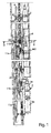
Figures 1 ,2 and3 illustrate respective side views of an ammunition hoist according to the present invention. - With reference to
figures 1 and2 , thereference number 1 indicates an ammunition hoist as a whole. -
Ammunition hoist 1 is designed to be preferably installed inside a warship or a submarine, so as to be positioned in a place where it can reach its maximum extension, in such a position that allows it to pass through the height of one or more decks of the ship or of the submarine. - In particular,
ammunition hoist 1 is arranged - when the ship or the submarine is in neutral trim - along a vertical axis and extends between a first lower level (typically the lowest deck of the ship or of the submarine, where there are the respective ammunition stores) and a second higher level (for example the deck house of a ship or the main deck of a submarine). - Ammunition hoist 1 comprises:
- a
hollow guide element 2, preferably with a circular shape, within which heavy ammunitions 3 for artillery, for example ship artillery, are caused to translate, said ammunitions comprising, in turn, a first part calledprojectile 3b (in use, the part that is fired out of the carriage) and a second part ofcharge 3a having a rear base (or terminal part) 3c (in use, the part aimed at the propulsion of the projectile). - a supporting
beam 4, set alongside the above-mentionedhollow guide element 2 and fitted to the body of a ship, along which ammunition 3 is parallelly moved; and - a
motor assembly 5 for the movement of ammunitions 3; in particular,motor assembly 5 comprises, besides anactual motor 5a, also anepicycloidal reducer 5b coupled to the above-mentionedmotor 5a, which, in turn, is mechanically coupled to apinion cogwheel 5c and to a manual handling system 5d, which is useful in case that, due to an absence of the power source ofmotor 5a, the motive power for the movement of the ammunitions is no longer available. - In particular, supporting
beam 4 presents such a length to pass through one or more decks of the ship or of the submarine on whichammunition hoist 1 is installed, so as to allow the ammunition to reach, for example, a height equal to the height of the deckhouse of a ship. -
Ammunition hoist 1 comprises, furthermore, a moving equipment 6, which is constrained in a sliding manner to supportingbeam 4, so as to slide along it in a rectilinear direction defined by a first vertical axis Y, which, by the way, is parallel to the direction along which supportingbeam 4 extends in its maximum length. Moving equipment 6 is designed so as to transport at least one ammunition 3 from the first to the second level of the ship or of the submarine. - More in detail, moving equipment 6 comprises at least one
track 6a, which slides along supportingbeam 4, since it is constrained to the latter by means of constraining means, such as guides and/or meshing wheels, which are able to exercise a low sliding friction during the translation along the first axis Y. - Moving equipment 6 comprises, furthermore, a
rack 7, which generates a meshing means together withpinion 5c ofmotor assembly 5.Rack 7 is arranged parallel to the first axis Y and is associated to atrack 6a; therefore, since the carriage has to move between the first and the second level during the rotation ofpinion 6a moving rack 7, the latter has to be long enough to allow thetrack 6a itself to start from the first level, even thoughmotor 5a andrelative pinion 5c are arranged at an intermediate level between the first and the second level. - In a preferred embodiment,
tracks 6a are more than one and are arranged in series with respect to one another, so that, when they are loaded with respective ammunition 3, ammunitions 3 are arranged in series, as well. - In order to constrain ammunition 3 to the
respective track 6a in a stable and safe manner, eachtrack 6a is provided withrespective blocking elements 10, which are respectively designed to lock ammunition 3 in a rear terminal part 3c and in an upper terminal part. - In particular, the blocking elements are:
- of a first type, also called lower "finger", which is adapted to support ammunition 3 during its translation along the first axis Y;
- of a second type, also called "anti-bounce finger", whose aim is that of locking the point of
projectile 3b, so as to prevent it from oscillating. - Since ammunition 3 is typically loaded on ammunition hoist 1 with the point of
projectile 3b upwards and charge 3a underprojectile 3b itself, the fingers of the first type support ammunition 3 from the side of base 3c. - For this reason, for each
track 6a, supportingelements 10 are spaced apart from one another at a distance which is substantially equal to the sum of the lengths of the projectile and of the charge. - Each supporting
element 10 is pivoted to therespective track 6a in correspondence to a pair of eyelets 10a, 10b and, therefore, it can rotate about a rotation axis X, which extends orthogonal to the first axis Y; as a consequence, the rotation plane of each supportingelement 10 is parallel to the plane along which thetracks 6a translate. -
Supporting beam 4 comprises a plurality oflateral guides beam 4 itself and extend along the whole length of the latter. - Said lateral guides allow a "control" of the rotation of supporting
elements 10, thus causing, according to their rotation, the locking and the release of ammunition 3 from therespective track 6a, allowing ammunition 3 itself to move by one step onmobile track 6a insidehollow guide element 2. Alternatively, with a different configuration of supportingelements 10, supportingelements 10 themselves also allow the ammunition to be delivered to the fixed supports ofhollow guide element 2 itself. - As illustrated more in detail in
figure 3 , in particular, for each side of supportingbeam 4, there is a pair of parallellateral guides exchange deviators 20, each of which is provided with arespective actuator 20a. - Supporting
elements 10 extend beyond thetracks 6a until they reach the area in correspondence tolateral guides - During the translation of ammunition 3 operated by
motor 5a, which - once set in rotation - rotatespinion 5c, which, by meshing withrack 7, movestrack 6a along the first axis 11, when pin 10c of a blockingelement 10 meets anexchange deviator 20, this pin 10c can either continue its travel on the lateral guide in which it has traveled until now, or, alternatively, exchange its position and move on the lateral guide parallel to the previous one, according to the position ofexchange deviator 20 itself. - By changing its position between one
lateral guide 11a and the other 11b, pin 10c ends up arranged at two different distances with respect to the rotation axis and, consequently, it causes the rotation of the supporting element itself, since the rotation point is fixed with respect totrack 6a. -
Exchange deviators 20 are arranged at a distance from one another, which is measured along the direction of maximum extension of the supporting beam and is such that it allows the opening and the closing of the different supportingelements 10 when a new ammunition 3 is loaded and, consequently, when the ammunition arranged at the highest height is unloaded. - On the two opposite sides of supporting
beam 4,exchange deviators 20 are arranged at a same height with respect to the ends ofbeam 4 itself. - In detail, when an ammunition has to be transported between the first and the second level (strike-up phase), with an empty hoist, first of all
rack 7 and, consequently, tracks 6 are brought to the first level by means of a rotation of pinion 6c operated bymotor assembly 5; when the height equal to the first level is reached,exchange deviators 20 cause the pins of supportingelements 10 to move, so as produce, by means of a rotation, their opening (supporting fingers), so that first ammunition 3 can be loaded. Subsequently,motor 5a is caused to rotate in an opposite direction with respect to the previous one, so as to allow the lifting of track 6 and, consequently, of the first ammunition 3. When the lifting of the first ammunition 3 has ended,motor 5a reverses again the motion, so as to bring down againtrack 6a. If the hoist according to the present invention can simultaneously transport different ammunitions, the previous step of "ending the lifting of ammunition 3" does not correspond to the transfer of ammunition 3 itself to the second and highest level, but, on the contrary, ammunition 3 is transferred to an intermediate level, in correspondence to which there arefurther exchange deviators 20, which allow the rotation and the subsequent opening and closing of supportingelements 10 respectively of the lower and of the upper track 6. The whole phase involving the translation of ammunitions 3 between the first and the second level occurs in an automatic way. -
Exchange deviators 20, furthermore, also allow ammunition hoist 1 according to the present invention to perform the so-called "strike-down" of the ammunition inside thehollow guide element 2. In detail, the "strike-down" phase is an automatic operation, through which ammunitions 3 can be brought back from the duct of ammunition hoist 1 according to the present invention to the store. - Thus, ammunition hoist 1 substantially allows not only an upwards translation of ammunitions 3 starting from the lower level, but also a downwards movement of ammunitions 3. Therefore,
hoist 1 according to the present invention has a reversible operation and is automated both in the strike-up phase and in the strike-down phase. - The automation of the strike-up and strike-down phases is supervised by electronic control means. Said electronic control means can either interact exclusively with
ammunition hoist 1 according to the present invention or, alternatively, have a data processing capability that they share with other electromechanical systems. - During this phase, auxiliary blocking elements 10a (also known as non-return pawls) intervene in the same position of the blocking fingers, i.e. on the base of
charge 3b, thus temporarily locking ammunition 3; auxiliary blocking elements 10a, unlike blockingelements 10, are fixed with respect to the ship and are not mobile like the rest of moving equipment 6. - Besides the above-mentioned ammunitions of the standard type, which have been previously described, ammunition hoist 1 according to the present invention can also use ammunitions of a different type, such as, for example, HEFSDS ammunitions (High Explosives Fin Stabilized Discarding Sabot), which basically are subcalibre, non self-propelled ammunitions having a guided version comprising aerodynamic controls, inertial/GPS navigation and, in some sub-types, a terminal guidance system; these ammunitions, nowadays called Vulcano, are characterized by a very long range (up to 120 km) and a high degree of accuracy (CEP < 20 m) .
- The advantages of ammunition hoist 1 according to the present invention are known in the light of the previous description. In particular, it allows the translation of one or more ammunitions inside a ship or a submarine, between a first level and a second level distinct from one another and spaced apart by one or more decks, with a
single motor 5a and by means of a moving equipment, which can be configured in a modular manner by changing the number of tracks 6 and the subsequent length ofrack 7. - For this reason, ammunition hoist 1 according to the present invention can be easily adjusted to different configurations and is not limited, thanks to its easy installation, neither to the number of decks of the ship or of the submarine nor to the dimension of ammunitions 3 to be translated.
- Some variations can be applied to the device described above. More in detail,
motor assembly 5 can be replaced by an oleodynamic system. - Furthermore, the rack can be replaced by a similar meshing means, such as a chain coupled to
pinion 5c.
Claims (15)
- Ammunition hoist (1), comprising a supporting beam (4) set alongside said hollow guide element, and a movement system (5), for enabling movement of said at least one ammunition (3) along said supporting beam (4) between a first level and a second level set at a different height with respect to one another;
said ammunition hoist (1) being characterized in that:- it comprises a moving equipment (6), sliding with respect to said supporting beam (4) and to which said ammunition (3) is associated at least temporarily; and- said movement of said ammunition (3) occurs in an automated way from and towards said first or second level. - Ammunition hoist according to claim 1, wherein said moving element (6) comprises:- at least one track (6a), which is mobile with respect to said supporting element (4);and wherein said moving equipment (6) moves axially along a first axis parallel to a direction of maximum extension of said supporting beam (4).
- Ammunition hoist according to claim 2, wherein said moving equipment (6) further comprises means (7) for meshing with said movement system (5).
- Ammunition hoist according to claim 3, wherein said meshing means (7) is a rack and wherein said movement system (5) comprises a motor (5a), which in turn comprises at least one cogwheel (5c), which meshes on said rack (7).
- Ammunition hoist according to claim 3, wherein said meshing means (7) is a chain.
- Ammunition hoist according to claim 1, wherein said movement system (5) is an oleodynamic system.
- Ammunition hoist according to claim 1, wherein said moving equipment (6) comprises a plurality of elements (10) for blocking said ammunition (3), and wherein said supporting beam (4) comprises a plurality of guides or recesses (11a-11d) for guiding said blocking elements (10) .
- Ammunition hoist according to claim 2 and claim 7, wherein each of said blocking elements (10) is rotatably pivoted on a respective support of said track (6a) and turns about an axis of rotation (X).
- Ammunition hoist according to claim 8, wherein said axis of rotation (X) is set perpendicular to said first axis.
- Ammunition hoist according to claim 7, further comprising a plurality of exchange deviators (20) and a plurality of actuators (20a) for said exchange deviators (20); said plurality of exchange deviators (20) being configured for enabling rotation of said blocking elements (10).
- Ammunition hoist according to claim 7, wherein said guides (11a-11d) are set in pairs on each side of said supporting beam (4); each pair of guides (11a, 11b; 11c, 11d) comprising a first, internal guide (11a; 11c) and a second external, guide (11b; 11d).
- Ammunition hoist according to claim 10 and claim 11, wherein said exchange deviators (20) have a first position of use for translation of a pin (10c) of said blocking elements (10) from said first internal guide (11a; 11c) to said second external guide (11b; 11d) and a second position of use for translation of a pin (10c) of said blocking elements (10) from said second external guide (11b; 11d) to said first internal guide (11a; 11c).
- Ammunition hoist according to any one of the preceding claims, comprising a hollow guide element (2), for enabling passage within it of at least one ammunition (3).
- Ammunition hoist according to any one of the preceding claims, further comprising auxiliary blocking elements (10a) and wherein said ammunition (3) comprises a first part or projectile (3a) and a second part or charge (3b); said auxiliary blocking elements (10a) temporarily blocking said ammunition (3) at a point corresponding to a base of said charge (3b).
- Ammunition hoist according to any one of the preceding claims, further comprising electronic control means that supervise the movement of said ammunitions (3) between said first level and said second level.
Priority Applications (2)
| Application Number | Priority Date | Filing Date | Title |
|---|---|---|---|
| PL11167947T PL2392887T3 (en) | 2010-06-04 | 2011-05-27 | Ammunition hoist |
| SI201130032T SI2392887T1 (en) | 2010-06-04 | 2011-05-27 | Ammunition hoist |
Applications Claiming Priority (1)
| Application Number | Priority Date | Filing Date | Title |
|---|---|---|---|
| ITTO2010A000466A IT1400435B1 (en) | 2010-06-04 | 2010-06-04 | ELEVATOR FOR AMMUNITIONS. |
Publications (2)
| Publication Number | Publication Date |
|---|---|
| EP2392887A1 true EP2392887A1 (en) | 2011-12-07 |
| EP2392887B1 EP2392887B1 (en) | 2013-03-06 |
Family
ID=43590004
Family Applications (1)
| Application Number | Title | Priority Date | Filing Date |
|---|---|---|---|
| EP11167947A Active EP2392887B1 (en) | 2010-06-04 | 2011-05-27 | Ammunition hoist |
Country Status (15)
| Country | Link |
|---|---|
| US (1) | US8549981B2 (en) |
| EP (1) | EP2392887B1 (en) |
| JP (1) | JP5989973B2 (en) |
| KR (1) | KR101909281B1 (en) |
| BR (1) | BRPI1102344B1 (en) |
| CA (1) | CA2742337C (en) |
| DK (1) | DK2392887T3 (en) |
| ES (1) | ES2415891T3 (en) |
| HR (1) | HRP20130464T1 (en) |
| IT (1) | IT1400435B1 (en) |
| PL (1) | PL2392887T3 (en) |
| PT (1) | PT2392887E (en) |
| RS (1) | RS52858B (en) |
| SG (1) | SG176414A1 (en) |
| SI (1) | SI2392887T1 (en) |
Cited By (1)
| Publication number | Priority date | Publication date | Assignee | Title |
|---|---|---|---|---|
| DE202015007518U1 (en) | 2015-10-29 | 2015-11-17 | Metallverarbeitungsgesellschaft Schubert & Co. (Gmbh & Co. Kg) | Ammunition lift for ships |
Families Citing this family (4)
| Publication number | Priority date | Publication date | Assignee | Title |
|---|---|---|---|---|
| KR101592292B1 (en) * | 2014-06-12 | 2016-02-05 | 국방과학연구소 | Munitions carrier and operation method thereof |
| RU198043U1 (en) * | 2019-07-02 | 2020-06-16 | Открытое акционерное общество "Машиностроительный завод "АРСЕНАЛ" | SHIP ARTILLERY INSTALLATION STORE |
| RU201561U1 (en) * | 2020-08-11 | 2020-12-21 | Открытое акционерное общество "Машиностроительный завод "АРСЕНАЛ" | AMMUNITION SHOP |
| RU201560U1 (en) * | 2020-08-11 | 2020-12-21 | Открытое акционерное общество "Машиностроительный завод "АРСЕНАЛ" | SHIP ARTILLERY AMMUNITION SHOP |
Citations (3)
| Publication number | Priority date | Publication date | Assignee | Title |
|---|---|---|---|---|
| FR689909A (en) * | 1929-04-22 | 1930-09-12 | Anciens Ets Sautter Harle | Improvements made to norias or other lifting devices |
| FR960287A (en) * | 1950-04-15 | |||
| US5131316A (en) * | 1991-07-12 | 1992-07-21 | General Electric Company | Autoloading apparatus for tank cannon |
Family Cites Families (9)
| Publication number | Priority date | Publication date | Assignee | Title |
|---|---|---|---|---|
| FR960284A (en) | 1950-04-15 | |||
| US3122967A (en) * | 1964-03-03 | Ammunition handling- and loading system for major caliber guns | ||
| US2855828A (en) * | 1950-03-31 | 1958-10-14 | Philias H Girouard | Rapid fire gun turret apparatus |
| US3218930A (en) * | 1952-08-27 | 1965-11-23 | Philias H Girouard | Gun mount with ammunition supplying means |
| SE428247B (en) * | 1979-06-07 | 1983-06-13 | Bofors Ab | DEVICE FOR AUTOMATIC TRANSFER OF SHOOTS AT AN ARTILLERY PIPE |
| US4398447A (en) * | 1981-02-19 | 1983-08-16 | Fmc Corporation | Vertical loading system for a gun mount |
| US4495853A (en) * | 1982-07-13 | 1985-01-29 | Fmc Corporation | Fixed elevation automatic loading system for fixed ammunition |
| CA2070510A1 (en) * | 1991-07-12 | 1993-01-13 | Keith Edward Lawrence | Apparatus for autoloading tank cannons |
| IT1399814B1 (en) * | 2010-04-27 | 2013-05-03 | Oto Melara Spa | METHOD AND SYSTEM OF LOADING AND DOWNLOADING BULLETS IN A MAGAZINE FOR FIREARMS. |
-
2010
- 2010-06-04 IT ITTO2010A000466A patent/IT1400435B1/en active
-
2011
- 2011-05-27 RS RS20130205A patent/RS52858B/en unknown
- 2011-05-27 PL PL11167947T patent/PL2392887T3/en unknown
- 2011-05-27 ES ES11167947T patent/ES2415891T3/en active Active
- 2011-05-27 DK DK11167947.8T patent/DK2392887T3/en active
- 2011-05-27 PT PT111679478T patent/PT2392887E/en unknown
- 2011-05-27 SI SI201130032T patent/SI2392887T1/en unknown
- 2011-05-27 EP EP11167947A patent/EP2392887B1/en active Active
- 2011-05-30 CA CA2742337A patent/CA2742337C/en active Active
- 2011-05-31 SG SG2011039435A patent/SG176414A1/en unknown
- 2011-05-31 BR BRPI1102344-9A patent/BRPI1102344B1/en active IP Right Grant
- 2011-06-01 JP JP2011123047A patent/JP5989973B2/en active Active
- 2011-06-02 US US13/151,931 patent/US8549981B2/en active Active
- 2011-06-03 KR KR1020110053824A patent/KR101909281B1/en active Active
-
2013
- 2013-05-27 HR HRP20130464AT patent/HRP20130464T1/en unknown
Patent Citations (3)
| Publication number | Priority date | Publication date | Assignee | Title |
|---|---|---|---|---|
| FR960287A (en) * | 1950-04-15 | |||
| FR689909A (en) * | 1929-04-22 | 1930-09-12 | Anciens Ets Sautter Harle | Improvements made to norias or other lifting devices |
| US5131316A (en) * | 1991-07-12 | 1992-07-21 | General Electric Company | Autoloading apparatus for tank cannon |
Cited By (3)
| Publication number | Priority date | Publication date | Assignee | Title |
|---|---|---|---|---|
| DE202015007518U1 (en) | 2015-10-29 | 2015-11-17 | Metallverarbeitungsgesellschaft Schubert & Co. (Gmbh & Co. Kg) | Ammunition lift for ships |
| DE102015014002B3 (en) | 2015-10-29 | 2017-03-30 | Metallverarbeitungsgesellschaft Schubert & Co. (Gmbh & Co. Kg) | Ammunition lift for ships |
| EP3214399A1 (en) | 2015-10-29 | 2017-09-06 | Metallverarbeitungsgesellschaft Schubert & Co. (GmbH & Co. KG) | Ammunition elevaotr for ships |
Also Published As
| Publication number | Publication date |
|---|---|
| US20110315001A1 (en) | 2011-12-29 |
| JP2011257127A (en) | 2011-12-22 |
| KR101909281B1 (en) | 2018-10-17 |
| SI2392887T1 (en) | 2013-10-30 |
| CA2742337C (en) | 2019-03-19 |
| IT1400435B1 (en) | 2013-05-31 |
| RS52858B (en) | 2013-12-31 |
| BRPI1102344A2 (en) | 2012-12-18 |
| ES2415891T3 (en) | 2013-07-29 |
| KR20110133446A (en) | 2011-12-12 |
| ITTO20100466A1 (en) | 2011-12-05 |
| PL2392887T3 (en) | 2013-09-30 |
| BRPI1102344B1 (en) | 2020-07-14 |
| PT2392887E (en) | 2013-06-04 |
| SG176414A1 (en) | 2011-12-29 |
| EP2392887B1 (en) | 2013-03-06 |
| DK2392887T3 (en) | 2013-06-10 |
| CA2742337A1 (en) | 2011-12-04 |
| HRP20130464T1 (en) | 2013-08-31 |
| US8549981B2 (en) | 2013-10-08 |
| JP5989973B2 (en) | 2016-09-07 |
Similar Documents
| Publication | Publication Date | Title |
|---|---|---|
| EP2392887B1 (en) | Ammunition hoist | |
| AU2021266330B2 (en) | Handling robot and method for retrieving inventory item based on handling robot | |
| KR102384486B1 (en) | Rocket launch module and rocket launch vehicle | |
| JP5986711B2 (en) | A system for moving objects in a warehouse | |
| KR102434532B1 (en) | Apparatus for launching weapon of underwater moving body | |
| KR100797752B1 (en) | Lifting device for unmanned aerial vehicle | |
| ES2374575T3 (en) | GRAND CALIBER NAVAL CANNON. | |
| US2987963A (en) | Boom missile loader | |
| EA021655B1 (en) | Starting device | |
| KR101809745B1 (en) | System for moving crates for storing objects in a warehouse | |
| US3162088A (en) | Missile launching system | |
| JP6707596B2 (en) | Laser type automated guided vehicle and automated guided vehicle system | |
| EP1075637B1 (en) | Method and device for handling propelling charges in fully and semi-automatic loading systems for artillery guns | |
| SU1623927A2 (en) | Reloader | |
| RU2287127C2 (en) | Rocket launcher | |
| HK40098020A (en) | Handling robot and method for retrieving inventory item based on handling robot | |
| KR20200043138A (en) | Submarine to support weapons in water | |
| HK40018042A (en) | Handling robot and method for retrieving inventory item based on handling robot | |
| HK40018042B (en) | Handling robot and method for retrieving inventory item based on handling robot | |
| JP2004314867A (en) | Ship launcher loading device |
Legal Events
| Date | Code | Title | Description |
|---|---|---|---|
| AK | Designated contracting states |
Kind code of ref document: A1 Designated state(s): AL AT BE BG CH CY CZ DE DK EE ES FI FR GB GR HR HU IE IS IT LI LT LU LV MC MK MT NL NO PL PT RO RS SE SI SK SM TR |
|
| AX | Request for extension of the european patent |
Extension state: BA ME |
|
| PUAI | Public reference made under article 153(3) epc to a published international application that has entered the european phase |
Free format text: ORIGINAL CODE: 0009012 |
|
| 17P | Request for examination filed |
Effective date: 20120606 |
|
| GRAP | Despatch of communication of intention to grant a patent |
Free format text: ORIGINAL CODE: EPIDOSNIGR1 |
|
| GRAC | Information related to communication of intention to grant a patent modified |
Free format text: ORIGINAL CODE: EPIDOSCIGR1 |
|
| GRAC | Information related to communication of intention to grant a patent modified |
Free format text: ORIGINAL CODE: EPIDOSCIGR1 |
|
| GRAS | Grant fee paid |
Free format text: ORIGINAL CODE: EPIDOSNIGR3 |
|
| GRAA | (expected) grant |
Free format text: ORIGINAL CODE: 0009210 |
|
| AK | Designated contracting states |
Kind code of ref document: B1 Designated state(s): AL AT BE BG CH CY CZ DE DK EE ES FI FR GB GR HR HU IE IS IT LI LT LU LV MC MK MT NL NO PL PT RO RS SE SI SK SM TR |
|
| REG | Reference to a national code |
Ref country code: GB Ref legal event code: FG4D |
|
| REG | Reference to a national code |
Ref country code: CH Ref legal event code: EP Ref country code: AT Ref legal event code: REF Ref document number: 599874 Country of ref document: AT Kind code of ref document: T Effective date: 20130315 |
|
| REG | Reference to a national code |
Ref country code: IE Ref legal event code: FG4D |
|
| REG | Reference to a national code |
Ref country code: DE Ref legal event code: R096 Ref document number: 602011000971 Country of ref document: DE Effective date: 20130502 |
|
| REG | Reference to a national code |
Ref country code: RO Ref legal event code: EPE |
|
| REG | Reference to a national code |
Ref country code: HR Ref legal event code: TUEP Ref document number: P20130464 Country of ref document: HR |
|
| REG | Reference to a national code |
Ref country code: PT Ref legal event code: SC4A Free format text: AVAILABILITY OF NATIONAL TRANSLATION Effective date: 20130529 |
|
| REG | Reference to a national code |
Ref country code: DK Ref legal event code: T3 |
|
| REG | Reference to a national code |
Ref country code: SE Ref legal event code: TRGR |
|
| REG | Reference to a national code |
Ref country code: AT Ref legal event code: MK05 Ref document number: 599874 Country of ref document: AT Kind code of ref document: T Effective date: 20130306 |
|
| REG | Reference to a national code |
Ref country code: NO Ref legal event code: T2 Effective date: 20130306 Ref country code: ES Ref legal event code: FG2A Ref document number: 2415891 Country of ref document: ES Kind code of ref document: T3 Effective date: 20130729 |
|
| PG25 | Lapsed in a contracting state [announced via postgrant information from national office to epo] |
Ref country code: AT Free format text: LAPSE BECAUSE OF FAILURE TO SUBMIT A TRANSLATION OF THE DESCRIPTION OR TO PAY THE FEE WITHIN THE PRESCRIBED TIME-LIMIT Effective date: 20130306 |
|
| REG | Reference to a national code |
Ref country code: NL Ref legal event code: T3 |
|
| PG25 | Lapsed in a contracting state [announced via postgrant information from national office to epo] |
Ref country code: LV Free format text: LAPSE BECAUSE OF FAILURE TO SUBMIT A TRANSLATION OF THE DESCRIPTION OR TO PAY THE FEE WITHIN THE PRESCRIBED TIME-LIMIT Effective date: 20130306 |
|
| REG | Reference to a national code |
Ref country code: GR Ref legal event code: EP Ref document number: 20130401068 Country of ref document: GR Effective date: 20130711 |
|
| REG | Reference to a national code |
Ref country code: HR Ref legal event code: T1PR Ref document number: P20130464 Country of ref document: HR |
|
| REG | Reference to a national code |
Ref country code: PL Ref legal event code: T3 |
|
| REG | Reference to a national code |
Ref country code: EE Ref legal event code: FG4A Ref document number: E008322 Country of ref document: EE Effective date: 20130605 |
|
| REG | Reference to a national code |
Ref country code: HU Ref legal event code: AG4A Ref document number: E017056 Country of ref document: HU |
|
| PG25 | Lapsed in a contracting state [announced via postgrant information from national office to epo] |
Ref country code: CZ Free format text: LAPSE BECAUSE OF FAILURE TO SUBMIT A TRANSLATION OF THE DESCRIPTION OR TO PAY THE FEE WITHIN THE PRESCRIBED TIME-LIMIT Effective date: 20130306 Ref country code: IS Free format text: LAPSE BECAUSE OF FAILURE TO SUBMIT A TRANSLATION OF THE DESCRIPTION OR TO PAY THE FEE WITHIN THE PRESCRIBED TIME-LIMIT Effective date: 20130706 |
|
| REG | Reference to a national code |
Ref country code: SK Ref legal event code: T3 Ref document number: E 14552 Country of ref document: SK |
|
| PG25 | Lapsed in a contracting state [announced via postgrant information from national office to epo] |
Ref country code: MC Free format text: LAPSE BECAUSE OF FAILURE TO SUBMIT A TRANSLATION OF THE DESCRIPTION OR TO PAY THE FEE WITHIN THE PRESCRIBED TIME-LIMIT Effective date: 20130306 |
|
| PLBE | No opposition filed within time limit |
Free format text: ORIGINAL CODE: 0009261 |
|
| STAA | Information on the status of an ep patent application or granted ep patent |
Free format text: STATUS: NO OPPOSITION FILED WITHIN TIME LIMIT |
|
| 26N | No opposition filed |
Effective date: 20131209 |
|
| REG | Reference to a national code |
Ref country code: DE Ref legal event code: R097 Ref document number: 602011000971 Country of ref document: DE Effective date: 20131209 |
|
| REG | Reference to a national code |
Ref country code: HR Ref legal event code: ODRP Ref document number: P20130464 Country of ref document: HR Payment date: 20140403 Year of fee payment: 4 |
|
| PGFP | Annual fee paid to national office [announced via postgrant information from national office to epo] |
Ref country code: BG Payment date: 20140319 Year of fee payment: 4 |
|
| PGFP | Annual fee paid to national office [announced via postgrant information from national office to epo] |
Ref country code: RS Payment date: 20140324 Year of fee payment: 4 |
|
| PGFP | Annual fee paid to national office [announced via postgrant information from national office to epo] |
Ref country code: LT Payment date: 20140415 Year of fee payment: 4 Ref country code: IE Payment date: 20140512 Year of fee payment: 4 Ref country code: EE Payment date: 20140415 Year of fee payment: 4 |
|
| PGFP | Annual fee paid to national office [announced via postgrant information from national office to epo] |
Ref country code: FI Payment date: 20140512 Year of fee payment: 4 Ref country code: RO Payment date: 20140411 Year of fee payment: 4 Ref country code: SI Payment date: 20140418 Year of fee payment: 4 Ref country code: PT Payment date: 20130529 Year of fee payment: 4 Ref country code: SE Payment date: 20140513 Year of fee payment: 4 |
|
| PGFP | Annual fee paid to national office [announced via postgrant information from national office to epo] |
Ref country code: HU Payment date: 20140512 Year of fee payment: 4 Ref country code: BE Payment date: 20140513 Year of fee payment: 4 Ref country code: HR Payment date: 20140403 Year of fee payment: 4 |
|
| REG | Reference to a national code |
Ref country code: CH Ref legal event code: PL |
|
| PG25 | Lapsed in a contracting state [announced via postgrant information from national office to epo] |
Ref country code: LI Free format text: LAPSE BECAUSE OF NON-PAYMENT OF DUE FEES Effective date: 20140531 Ref country code: CH Free format text: LAPSE BECAUSE OF NON-PAYMENT OF DUE FEES Effective date: 20140531 |
|
| PG25 | Lapsed in a contracting state [announced via postgrant information from national office to epo] |
Ref country code: MT Free format text: LAPSE BECAUSE OF FAILURE TO SUBMIT A TRANSLATION OF THE DESCRIPTION OR TO PAY THE FEE WITHIN THE PRESCRIBED TIME-LIMIT Effective date: 20130306 |
|
| PG25 | Lapsed in a contracting state [announced via postgrant information from national office to epo] |
Ref country code: SM Free format text: LAPSE BECAUSE OF FAILURE TO SUBMIT A TRANSLATION OF THE DESCRIPTION OR TO PAY THE FEE WITHIN THE PRESCRIBED TIME-LIMIT Effective date: 20130306 |
|
| PG25 | Lapsed in a contracting state [announced via postgrant information from national office to epo] |
Ref country code: CY Free format text: LAPSE BECAUSE OF FAILURE TO SUBMIT A TRANSLATION OF THE DESCRIPTION OR TO PAY THE FEE WITHIN THE PRESCRIBED TIME-LIMIT Effective date: 20130306 |
|
| PG25 | Lapsed in a contracting state [announced via postgrant information from national office to epo] |
Ref country code: LU Free format text: LAPSE BECAUSE OF NON-PAYMENT OF DUE FEES Effective date: 20130527 Ref country code: MK Free format text: LAPSE BECAUSE OF FAILURE TO SUBMIT A TRANSLATION OF THE DESCRIPTION OR TO PAY THE FEE WITHIN THE PRESCRIBED TIME-LIMIT Effective date: 20130306 |
|
| REG | Reference to a national code |
Ref country code: PT Ref legal event code: MM4A Free format text: LAPSE DUE TO NON-PAYMENT OF FEES Effective date: 20151127 |
|
| REG | Reference to a national code |
Ref country code: HR Ref legal event code: PBON Ref document number: P20130464 Country of ref document: HR Effective date: 20150527 |
|
| REG | Reference to a national code |
Ref country code: LT Ref legal event code: MM4D Effective date: 20150527 |
|
| REG | Reference to a national code |
Ref country code: EE Ref legal event code: MM4A Ref document number: E008322 Country of ref document: EE Effective date: 20150531 |
|
| PG25 | Lapsed in a contracting state [announced via postgrant information from national office to epo] |
Ref country code: FI Free format text: LAPSE BECAUSE OF NON-PAYMENT OF DUE FEES Effective date: 20150527 Ref country code: LT Free format text: LAPSE BECAUSE OF NON-PAYMENT OF DUE FEES Effective date: 20150527 Ref country code: EE Free format text: LAPSE BECAUSE OF NON-PAYMENT OF DUE FEES Effective date: 20150531 |
|
| REG | Reference to a national code |
Ref country code: IE Ref legal event code: MM4A |
|
| PG25 | Lapsed in a contracting state [announced via postgrant information from national office to epo] |
Ref country code: RO Free format text: LAPSE BECAUSE OF NON-PAYMENT OF DUE FEES Effective date: 20150527 Ref country code: SE Free format text: LAPSE BECAUSE OF NON-PAYMENT OF DUE FEES Effective date: 20150528 Ref country code: HR Free format text: LAPSE BECAUSE OF NON-PAYMENT OF DUE FEES Effective date: 20150527 Ref country code: RS Free format text: LAPSE BECAUSE OF NON-PAYMENT OF DUE FEES Effective date: 20151208 Ref country code: PT Free format text: LAPSE BECAUSE OF NON-PAYMENT OF DUE FEES Effective date: 20151127 Ref country code: SI Free format text: LAPSE BECAUSE OF NON-PAYMENT OF DUE FEES Effective date: 20150528 |
|
| REG | Reference to a national code |
Ref country code: SI Ref legal event code: KO00 Effective date: 20160112 |
|
| REG | Reference to a national code |
Ref country code: FR Ref legal event code: PLFP Year of fee payment: 6 |
|
| PG25 | Lapsed in a contracting state [announced via postgrant information from national office to epo] |
Ref country code: IE Free format text: LAPSE BECAUSE OF NON-PAYMENT OF DUE FEES Effective date: 20150527 Ref country code: BG Free format text: LAPSE BECAUSE OF NON-PAYMENT OF DUE FEES Effective date: 20160331 |
|
| PG25 | Lapsed in a contracting state [announced via postgrant information from national office to epo] |
Ref country code: HU Free format text: LAPSE BECAUSE OF NON-PAYMENT OF DUE FEES Effective date: 20150528 |
|
| PGFP | Annual fee paid to national office [announced via postgrant information from national office to epo] |
Ref country code: PL Payment date: 20160316 Year of fee payment: 6 |
|
| PGFP | Annual fee paid to national office [announced via postgrant information from national office to epo] |
Ref country code: NL Payment date: 20160510 Year of fee payment: 6 |
|
| PGFP | Annual fee paid to national office [announced via postgrant information from national office to epo] |
Ref country code: DE Payment date: 20160524 Year of fee payment: 6 Ref country code: NO Payment date: 20160513 Year of fee payment: 6 Ref country code: ES Payment date: 20160414 Year of fee payment: 6 Ref country code: GB Payment date: 20160525 Year of fee payment: 6 Ref country code: GR Payment date: 20160415 Year of fee payment: 6 |
|
| PGFP | Annual fee paid to national office [announced via postgrant information from national office to epo] |
Ref country code: DK Payment date: 20160510 Year of fee payment: 6 Ref country code: FR Payment date: 20160412 Year of fee payment: 6 |
|
| PG25 | Lapsed in a contracting state [announced via postgrant information from national office to epo] |
Ref country code: BE Free format text: LAPSE BECAUSE OF NON-PAYMENT OF DUE FEES Effective date: 20150531 |
|
| REG | Reference to a national code |
Ref country code: DE Ref legal event code: R119 Ref document number: 602011000971 Country of ref document: DE |
|
| REG | Reference to a national code |
Ref country code: NO Ref legal event code: MMEP |
|
| REG | Reference to a national code |
Ref country code: DK Ref legal event code: EBP Effective date: 20170531 |
|
| REG | Reference to a national code |
Ref country code: NL Ref legal event code: MM Effective date: 20170601 |
|
| GBPC | Gb: european patent ceased through non-payment of renewal fee |
Effective date: 20170527 |
|
| PG25 | Lapsed in a contracting state [announced via postgrant information from national office to epo] |
Ref country code: NO Free format text: LAPSE BECAUSE OF NON-PAYMENT OF DUE FEES Effective date: 20170531 |
|
| PG25 | Lapsed in a contracting state [announced via postgrant information from national office to epo] |
Ref country code: GR Free format text: LAPSE BECAUSE OF NON-PAYMENT OF DUE FEES Effective date: 20171206 |
|
| REG | Reference to a national code |
Ref country code: FR Ref legal event code: ST Effective date: 20180131 |
|
| PG25 | Lapsed in a contracting state [announced via postgrant information from national office to epo] |
Ref country code: NL Free format text: LAPSE BECAUSE OF NON-PAYMENT OF DUE FEES Effective date: 20170601 |
|
| PG25 | Lapsed in a contracting state [announced via postgrant information from national office to epo] |
Ref country code: DK Free format text: LAPSE BECAUSE OF NON-PAYMENT OF DUE FEES Effective date: 20170531 Ref country code: DE Free format text: LAPSE BECAUSE OF NON-PAYMENT OF DUE FEES Effective date: 20171201 Ref country code: GB Free format text: LAPSE BECAUSE OF NON-PAYMENT OF DUE FEES Effective date: 20170527 |
|
| PG25 | Lapsed in a contracting state [announced via postgrant information from national office to epo] |
Ref country code: FR Free format text: LAPSE BECAUSE OF NON-PAYMENT OF DUE FEES Effective date: 20170531 |
|
| REG | Reference to a national code |
Ref country code: ES Ref legal event code: FD2A Effective date: 20180704 |
|
| PG25 | Lapsed in a contracting state [announced via postgrant information from national office to epo] |
Ref country code: ES Free format text: LAPSE BECAUSE OF NON-PAYMENT OF DUE FEES Effective date: 20170528 |
|
| PG25 | Lapsed in a contracting state [announced via postgrant information from national office to epo] |
Ref country code: AL Free format text: LAPSE BECAUSE OF FAILURE TO SUBMIT A TRANSLATION OF THE DESCRIPTION OR TO PAY THE FEE WITHIN THE PRESCRIBED TIME-LIMIT Effective date: 20130306 Ref country code: PL Free format text: LAPSE BECAUSE OF NON-PAYMENT OF DUE FEES Effective date: 20170527 |
|
| PGFP | Annual fee paid to national office [announced via postgrant information from national office to epo] |
Ref country code: IT Payment date: 20250507 Year of fee payment: 15 |
|
| PGFP | Annual fee paid to national office [announced via postgrant information from national office to epo] |
Ref country code: TR Payment date: 20250520 Year of fee payment: 15 Ref country code: SK Payment date: 20250520 Year of fee payment: 15 |