EP2393144A1 - Conducteur de connexion de bornes, batterie assemblée et procédé de fabrication d'une batterie assemblée - Google Patents
Conducteur de connexion de bornes, batterie assemblée et procédé de fabrication d'une batterie assemblée Download PDFInfo
- Publication number
- EP2393144A1 EP2393144A1 EP10735932A EP10735932A EP2393144A1 EP 2393144 A1 EP2393144 A1 EP 2393144A1 EP 10735932 A EP10735932 A EP 10735932A EP 10735932 A EP10735932 A EP 10735932A EP 2393144 A1 EP2393144 A1 EP 2393144A1
- Authority
- EP
- European Patent Office
- Prior art keywords
- conductor
- metal
- connecting terminals
- battery
- region
- Prior art date
- Legal status (The legal status is an assumption and is not a legal conclusion. Google has not performed a legal analysis and makes no representation as to the accuracy of the status listed.)
- Granted
Links
Images


Classifications
-
- H—ELECTRICITY
- H01—ELECTRIC ELEMENTS
- H01M—PROCESSES OR MEANS, e.g. BATTERIES, FOR THE DIRECT CONVERSION OF CHEMICAL ENERGY INTO ELECTRICAL ENERGY
- H01M50/00—Constructional details or processes of manufacture of the non-active parts of electrochemical cells other than fuel cells, e.g. hybrid cells
- H01M50/50—Current conducting connections for cells or batteries
- H01M50/502—Interconnectors for connecting terminals of adjacent batteries; Interconnectors for connecting cells outside a battery casing
- H01M50/514—Methods for interconnecting adjacent batteries or cells
- H01M50/516—Methods for interconnecting adjacent batteries or cells by welding, soldering or brazing
-
- H—ELECTRICITY
- H01—ELECTRIC ELEMENTS
- H01M—PROCESSES OR MEANS, e.g. BATTERIES, FOR THE DIRECT CONVERSION OF CHEMICAL ENERGY INTO ELECTRICAL ENERGY
- H01M50/00—Constructional details or processes of manufacture of the non-active parts of electrochemical cells other than fuel cells, e.g. hybrid cells
- H01M50/50—Current conducting connections for cells or batteries
-
- H—ELECTRICITY
- H01—ELECTRIC ELEMENTS
- H01M—PROCESSES OR MEANS, e.g. BATTERIES, FOR THE DIRECT CONVERSION OF CHEMICAL ENERGY INTO ELECTRICAL ENERGY
- H01M10/00—Secondary cells; Manufacture thereof
- H01M10/05—Accumulators with non-aqueous electrolyte
-
- H—ELECTRICITY
- H01—ELECTRIC ELEMENTS
- H01M—PROCESSES OR MEANS, e.g. BATTERIES, FOR THE DIRECT CONVERSION OF CHEMICAL ENERGY INTO ELECTRICAL ENERGY
- H01M10/00—Secondary cells; Manufacture thereof
- H01M10/05—Accumulators with non-aqueous electrolyte
- H01M10/058—Construction or manufacture
-
- H—ELECTRICITY
- H01—ELECTRIC ELEMENTS
- H01M—PROCESSES OR MEANS, e.g. BATTERIES, FOR THE DIRECT CONVERSION OF CHEMICAL ENERGY INTO ELECTRICAL ENERGY
- H01M50/00—Constructional details or processes of manufacture of the non-active parts of electrochemical cells other than fuel cells, e.g. hybrid cells
- H01M50/50—Current conducting connections for cells or batteries
- H01M50/502—Interconnectors for connecting terminals of adjacent batteries; Interconnectors for connecting cells outside a battery casing
- H01M50/503—Interconnectors for connecting terminals of adjacent batteries; Interconnectors for connecting cells outside a battery casing characterised by the shape of the interconnectors
-
- H—ELECTRICITY
- H01—ELECTRIC ELEMENTS
- H01M—PROCESSES OR MEANS, e.g. BATTERIES, FOR THE DIRECT CONVERSION OF CHEMICAL ENERGY INTO ELECTRICAL ENERGY
- H01M50/00—Constructional details or processes of manufacture of the non-active parts of electrochemical cells other than fuel cells, e.g. hybrid cells
- H01M50/50—Current conducting connections for cells or batteries
- H01M50/502—Interconnectors for connecting terminals of adjacent batteries; Interconnectors for connecting cells outside a battery casing
- H01M50/507—Interconnectors for connecting terminals of adjacent batteries; Interconnectors for connecting cells outside a battery casing comprising an arrangement of two or more busbars within a container structure, e.g. busbar modules
-
- H—ELECTRICITY
- H01—ELECTRIC ELEMENTS
- H01M—PROCESSES OR MEANS, e.g. BATTERIES, FOR THE DIRECT CONVERSION OF CHEMICAL ENERGY INTO ELECTRICAL ENERGY
- H01M50/00—Constructional details or processes of manufacture of the non-active parts of electrochemical cells other than fuel cells, e.g. hybrid cells
- H01M50/50—Current conducting connections for cells or batteries
- H01M50/502—Interconnectors for connecting terminals of adjacent batteries; Interconnectors for connecting cells outside a battery casing
- H01M50/521—Interconnectors for connecting terminals of adjacent batteries; Interconnectors for connecting cells outside a battery casing characterised by the material
- H01M50/522—Inorganic material
-
- H—ELECTRICITY
- H01—ELECTRIC ELEMENTS
- H01M—PROCESSES OR MEANS, e.g. BATTERIES, FOR THE DIRECT CONVERSION OF CHEMICAL ENERGY INTO ELECTRICAL ENERGY
- H01M50/00—Constructional details or processes of manufacture of the non-active parts of electrochemical cells other than fuel cells, e.g. hybrid cells
- H01M50/50—Current conducting connections for cells or batteries
- H01M50/543—Terminals
- H01M50/547—Terminals characterised by the disposition of the terminals on the cells
- H01M50/55—Terminals characterised by the disposition of the terminals on the cells on the same side of the cell
-
- H—ELECTRICITY
- H01—ELECTRIC ELEMENTS
- H01M—PROCESSES OR MEANS, e.g. BATTERIES, FOR THE DIRECT CONVERSION OF CHEMICAL ENERGY INTO ELECTRICAL ENERGY
- H01M50/00—Constructional details or processes of manufacture of the non-active parts of electrochemical cells other than fuel cells, e.g. hybrid cells
- H01M50/50—Current conducting connections for cells or batteries
- H01M50/543—Terminals
- H01M50/552—Terminals characterised by their shape
- H01M50/553—Terminals adapted for prismatic, pouch or rectangular cells
-
- H—ELECTRICITY
- H01—ELECTRIC ELEMENTS
- H01M—PROCESSES OR MEANS, e.g. BATTERIES, FOR THE DIRECT CONVERSION OF CHEMICAL ENERGY INTO ELECTRICAL ENERGY
- H01M2220/00—Batteries for particular applications
- H01M2220/20—Batteries in motive systems, e.g. vehicle, ship, plane
-
- Y—GENERAL TAGGING OF NEW TECHNOLOGICAL DEVELOPMENTS; GENERAL TAGGING OF CROSS-SECTIONAL TECHNOLOGIES SPANNING OVER SEVERAL SECTIONS OF THE IPC; TECHNICAL SUBJECTS COVERED BY FORMER USPC CROSS-REFERENCE ART COLLECTIONS [XRACs] AND DIGESTS
- Y02—TECHNOLOGIES OR APPLICATIONS FOR MITIGATION OR ADAPTATION AGAINST CLIMATE CHANGE
- Y02E—REDUCTION OF GREENHOUSE GAS [GHG] EMISSIONS, RELATED TO ENERGY GENERATION, TRANSMISSION OR DISTRIBUTION
- Y02E60/00—Enabling technologies; Technologies with a potential or indirect contribution to GHG emissions mitigation
- Y02E60/10—Energy storage using batteries
-
- Y—GENERAL TAGGING OF NEW TECHNOLOGICAL DEVELOPMENTS; GENERAL TAGGING OF CROSS-SECTIONAL TECHNOLOGIES SPANNING OVER SEVERAL SECTIONS OF THE IPC; TECHNICAL SUBJECTS COVERED BY FORMER USPC CROSS-REFERENCE ART COLLECTIONS [XRACs] AND DIGESTS
- Y02—TECHNOLOGIES OR APPLICATIONS FOR MITIGATION OR ADAPTATION AGAINST CLIMATE CHANGE
- Y02P—CLIMATE CHANGE MITIGATION TECHNOLOGIES IN THE PRODUCTION OR PROCESSING OF GOODS
- Y02P70/00—Climate change mitigation technologies in the production process for final industrial or consumer products
- Y02P70/50—Manufacturing or production processes characterised by the final manufactured product
-
- Y—GENERAL TAGGING OF NEW TECHNOLOGICAL DEVELOPMENTS; GENERAL TAGGING OF CROSS-SECTIONAL TECHNOLOGIES SPANNING OVER SEVERAL SECTIONS OF THE IPC; TECHNICAL SUBJECTS COVERED BY FORMER USPC CROSS-REFERENCE ART COLLECTIONS [XRACs] AND DIGESTS
- Y10—TECHNICAL SUBJECTS COVERED BY FORMER USPC
- Y10T—TECHNICAL SUBJECTS COVERED BY FORMER US CLASSIFICATION
- Y10T29/00—Metal working
- Y10T29/49—Method of mechanical manufacture
- Y10T29/49002—Electrical device making
- Y10T29/49108—Electric battery cell making
Definitions
- the present invention relates to a conductor for connecting terminals to connect terminals and the like, to each other, of a plurality of batteries, an assembled battery provided by connecting the terminals, to each other, of the plurality of the batteries by the conductors for connecting terminals, and a method for producing the assembled battery provided by connecting the terminals, to each other, of the plurality of batteries by the conductors for connecting terminals.
- the conductor for connecting terminals according to the present invention may be preferably used in an assembled battery provided by connecting terminals, to each other, of non-aqueous electrolyte secondary batteries having a positive-electrode terminal made of aluminum, etc.
- a component material of the positive-electrode terminal in the non-aqueous electrolyte secondary battery aluminum or an aluminum alloy which is not soluble in non-aqueous electrolyte at a positive electrode potential is preferably used.
- a component material of a negative-electrode terminal copper which is not alloyed with a negative-electrode active material is used in many cases.
- the positive-electrode terminal including the aluminum and the like is connected to the negative-electrode terminal of another non-aqueous electrolyte secondary battery or a terminal of an external device through a conductor for connecting terminals including copper, nickel, or iron, etc.
- the positive-electrode terminal may not be easily welded to the conductor for connecting terminals because the aluminum, etc. is lower in melting point and is higher in specific heat capacity than the copper, nickel or iron, etc. is.
- the conductor for connecting terminals including aluminum, etc. may not be easily welded to a positive-electrode terminal including copper, etc. and the negative-electrode terminal including copper, nickel, or iron, etc.
- a current extracting lead plate including a clad material having two-layer structure provided by attaching an aluminum layer and a nickel layer is arranged so as to abut on a bottom part of an exterior may of a battery whose aluminum layer includes aluminum, and fixed thereto by welding and the like.
- the nickel layer of the current extracting lead plate may easily be welded to a connecting lead plate serving as a conductor for connecting terminals made of another metal such as copper, nickel, or iron, so that the bottom part of the exterior may and the connecting lead plate may be surely connected to each other through the current extracting lead plate 2.
- the positive-electrode terminal including aluminum and the like has a part which includes copper, nickel, or iron and projects outward from the battery exterior case, the part may be welded to the positive-electrode terminal through the nickel layer of the current extracting lead plate.
- Patent document 2 discloses a method for connecting non-aqueous electrolyte secondary batteries in series through a conductor for connecting terminals serving as a plywood 5 provided by attaching an aluminum plate 5a and a copper plate 5b across the board.
- the plywood 5 is provided such that the aluminum plate 5a and the copper plate 5b are pressed through a mill roll while being heated at a predetermined temperature.
- the plywood 5 is twisted or bent so as to reverse the positional relationship between the aluminum plate and the same plate to allow the aluminum plate 5a of the plywood 5 to be brought in contact with a positive-electrode terminal 1 including aluminum and the like, and allow the copper plate 5b to be brought in contact with a negative-electrode terminal 4 including copper and the like, and they are welded, respectively.
- the non-aqueous electrolyte secondary battery including the positive-electrode terminal including aluminum or an aluminum alloy and the negative-electrode terminal including copper or nickel, etc. since aluminum is low in melting point and high in specific heat capacity compared with copper, nickel, or iron, the problem is that it is difficult to surely weld the negative electrode to the conductor for connecting terminals including aluminum, and it is difficult to surely weld the positive electrode to the conductor for connecting terminals including copper.
- the inventors have found the problem that when the electrode terminals of the batteries are connected through a conductor for connecting terminals 5 including the two-layer clad material formed all over in the longitudinal direction as shown in Fig. 6 , preferable welding to one electrode terminal may be performed, but preferable welding to the other electrode terminal may not be performed.
- the inventors tried resistance welding by bringing the aluminum plate 5a of the conductor for connecting terminals 5 in contact with a positive-electrode terminal 1 including aluminum, etc. of the one battery and sandwiching both of them by welding heads 6 and 6, and also tried resistance welding by bringing the copper plate 5b of the conductor for connecting terminals 5 in contact with a negative-electrode terminal 4 including copper, etc.
- the resistance welding may be easily performed between the positive-electrode terminal 1 and the conductor for connecting terminals 5, but regarding the welding between the conductor for connecting terminals 5 and the negative-electrode terminal 4, the welding may not be sufficiently performed between the negative-electrode terminal 4 and the copper plate 5b because the aluminum plate 5a having a melting point lower than that of the copper plate 5b melts before the welding is performed between the negative-electrode terminal 4 and the copper plate 5b. It is an additional object of the present invention to enhance connection strength and to reduce electric resistance by ensuring welding between both terminals of the positive electrode and the negative electrode, and the conductor for connecting terminals.
- a step difference corresponding to a thickness of the former plate material is formed at a boundary between both plate materials.
- the inventors have found that electric corrosion is caused by attachment and accumulation of water droplets at the boundary, and further found that the accumulation of the water droplets is caused by the step difference. Note that the electric corrosion is a corrosion phenomenon due to an electrochemical reaction caused by water droplets interposed between different metals. It is an additional object of the present invention to prevent the conductor for connecting terminals from deteriorating due to the electric corrosion.
- a conventional structure to connect the batteries mainly employs a structure in which an upper surface of the positive-electrode terminal and an upper surface of the negative-electrode terminal are coupled with the conductor for connecting terminals.
- the battery exterior case is designed to be thin, but as it is thinned, the connection strength is problematically lowered. Therefore, it has been recognized that there is a trade-off between the connection strength and the battery thickness.
- the vehicle equipped with the assembled battery has the problem that the electric corrosion is generated in a connection part of the conductor for connecting terminals constituted by connecting different kinds of metals. The inventors have found that this problem arises as a prominent phenomenon in an automobile used in a cold region.
- a conductor for connecting terminals being formed in such a manner that at least a plate-shaped part including a first metal, and a plate-shaped part including a second metal having a melting point higher than that of the first metal are overlapped with each other, a first region having the exposed first metal, and a second region having the exposed second metal are formed on one surface, the second metal is formed so as to be exposed to a region opposed to the second region, in the other surface, and there is substantially no step difference at an interface between the first region and the second region in a thickness direction.
- a first region formed on the one surface of the conductor for connecting terminals and having an exposed first metal having a low melting point may be easily and surely welded to a terminal
- a second region formed on the one surface of the conductor for connecting terminals and having an exposed second metal having a high melting point, or a region opposed to the second region, in the other surface and having the exposed second metal may be easily and surely welded to the terminal with sufficient strength.
- the conductor for connecting terminals of the present invention since there is substantially no step difference at the boundary between the first region and the second region of the conductor for connecting terminals, the conductor for connecting terminals is prevented from deteriorating due to the electric corrosion.
- the mechanisms provided by substantially eliminating the step difference are as follows.
- the water droplet is not attached to the boundary between the first region and the second region. Even when water droplets are attached, the water droplets may be easily moved to another place because there is no step difference. Since the step difference which prevents an air current to be forcedly applied to cool down the battery does not exist, water may be smoothly evaporated with the air current.
- a contact area between the water droplets and the boundary part is small compared with the case where the step difference exists, and electron transfer resistance increases because an electron transfer distance between the different kinds of metals increases, whereby a corrosion reaction is prevented from being progressed.
- the battery may be used with the conductor for connecting terminals arranged between the side face of the positive-electrode terminal including aluminum or aluminum alloy, and the side face of the other terminal including the metal having a melting point higher than that of the aluminum or aluminum alloy. That is, the conductor for connecting terminals may be surely welded to each terminal.
- the first region formed on the one surface preferably includes an aluminum member made of aluminum or an aluminum alloy
- the second region formed on the one surface or the region opposed to the second region, in the other surface preferably includes a material such as a metal having a melting point higher than that of the aluminum or aluminum alloy.
- the aluminum member is brought into contact with the positive-electrode terminal of the non-aqueous electrolyte secondary battery and connected and fixed thereto strongly by welding, and a part other than the aluminum member of the conductor for connecting terminals is brought in contact with the other terminal and connected and fixed thereto strongly by welding.
- an assembled battery including: at least two batteries each having a battery container, and a positive-electrode terminal and a negative-electrode terminal projecting upward from the battery container, and a conductor for connecting terminals formed in such a manner that at least a plate-shaped part including a first metal, and a plate-shaped part including a second metal having a melting point higher than that of the first metal are overlapped with each other, a first region having the exposed first metal, and a second region having the exposed second metal are formed on one surface, and the second metal is formed so as to be exposed to a region opposed to the second region, in the other surface, wherein the batteries are arranged in such a manner that side faces having a largest area of side faces of the battery containers are opposed, and the conductor for connecting terminals is arranged between a terminal of one battery and a terminal of the other battery, the first region of the conductor for connecting terminals is connected to an opposed face of the terminal of the one battery, and the
- the battery when the side faces of the terminals of the batteries are connected through the conductor for connecting terminals, strong and sure welding to both terminals may be performed, and the battery may be designed to be thinner.
- the connection strength and the battery thickness have the trade-off, but according to the present invention, the high-level connection strength to satisfy the specification of the assembled battery to be mounted on an automobile may be ensured, and the battery thickness may be designed to be thin to the level in which preferable cooling characteristics may be ensured.
- the plurality of non-aqueous electrolyte secondary batteries are used, and it is preferable that the terminals of the batteries are connected in series with the conductors for connecting terminals of the present invention.
- the configuration of a vehicle of the present invention is characterized by including the assembled battery having the above characteristics.
- a method for producing an assembled battery using a conductor for connecting terminals formed in such a manner that at least a plate-shaped part including a first metal, and a plate-shaped part including a second metal having a melting point higher than that of the first metal are overlapped with each other, a first region having the exposed first metal, and a second region having the exposed second metal are formed on one surface, and the second metal is formed so as to be exposed to a region opposed to the second region, in the other surface, and including: a step of arranging the conductor for connecting terminals and a terminal of a battery in such a manner that the first region is brought in contact with the terminal of the battery, arranging a pair of welding heads so as to sandwich the terminal of the battery and the conductor for connecting terminals, and applying a current from the welding head to the conductor for connecting terminals and the terminal of the battery, and a step of arranging the conductor for connecting terminals and a terminal of another battery in such a manner that at least a plate-shaped part including a first
- the method for producing the assembled battery of the present invention in the case where the terminals of the batteries are connected to each other with the conductor for connecting terminals, strong and sure welding to both terminals may be realized. Furthermore, since the conductor for connecting terminals may be easily welded to the positive-electrode terminal and the other terminal, steps of connecting the terminals of the batteries using the conductor for connecting terminals may be simplified. Therefore, the step of welding the conventional current extracting lead plate, and the step of processing the outward projection part so that the part includes copper, nickel, or iron, in the positive-electrode terminal including aluminum may be omitted, and workability (process efficiency) in connecting and fixing the terminals of the batteries may be enhanced.
- the conductor for connecting terminals of the present invention may be strongly and surely welded to the positive-electrode terminal and the negative-electrode terminal of the batteries.
- the conductor for connecting terminals when being formed in such a manner that there is substantially no step difference in the thickness direction at the boundary between the first region and the second region, the conductor for connecting terminals may be effectively prevented from deteriorating due to the electric corrosion.
- the step of connecting the terminals of the batteries with the conductor for connecting terminals may be considerably simplified, and production cost of the assembled battery may be reduced.
- the battery used in the assembled battery may be designed to be thinner.
- each battery of the assembled battery may be formed into the thin type, a space for setting the assembled battery may be saved, so that the vehicle may mount the assembled battery having higher capacity than the assembled battery in the same space.
- Fig. 1 shows an assembled battery serving as one example of the present invention.
- a plurality of non-aqueous electrolyte secondary batteries 7 are arranged in their thickness direction, and a positive-electrode terminal 1 and a negative-electrode terminal 4 of the adjacent non-aqueous electrolyte secondary batteries 7 are connected in series through a conductor for connecting terminals 8, whereby the assembled battery is constituted.
- Fig. 1 shows that an arranged direction of the non-aqueous electrolyte secondary batteries 7 arranged in their thickness direction is a front-back direction, a width direction of the non-aqueous electrolyte secondary battery 7 is a right-left direction, and a height direction of the non-aqueous electrolyte secondary battery 7 is an up-down direction.
- a battery exterior case of each non-aqueous electrolyte secondary battery 7 includes a rectangular-box-shaped stainless steel battery container 7a formed so that its thickness is shorter than its width, and a stainless steel lid plate 7b to cover an top-end opening part of the battery container 7a.
- the battery container 7a holds a power generation component, and filled with an electrolyte solution. Furthermore, the positive-electrode terminal 1 projects upward from an upper surface of the lid plate 7b on the right side, and the negative-electrode terminal 4 projects upward from the upper surface thereof on the left side.
- Each of these terminals 1 and 4 is formed into a rectangular plate shape in which a surface directed in the front-back direction (thickness direction) is the largest.
- the positive-electrode terminal 1 includes aluminum or an aluminum alloy, and its lower part penetrates the insulation-sealed lid plate 7b so as to be connected to a positive electrode of the power generation component held in the battery container 7a.
- the negative-electrode terminal 4 includes copper or a copper alloy, and its lower part penetrates the insulation-sealed lid plate 7b so as to be connected to a negative electrode of the power generation component held in the battery container 7a.
- the non-aqueous electrolyte secondary batteries 7 are arranged in the front-back direction in such a manner that the largest side surfaces of the battery containers 7a are overlapped with each other.
- the right and left sides of the non-aqueous electrolyte secondary batteries 7 are alternately opposed so that the positive-electrode terminal 1 and the negative-electrode terminal 4 of the adjacent non-aqueous electrolyte secondary batteries 7 and 7 are close to each other.
- the positive-electrode terminal 1 provided on the right side of the non-aqueous electrolyte secondary battery 7 which is arranged in first front is connected to the negative-electrode terminal 4 provided also on the right side of the second non-aqueous electrolyte secondary battery 7 which is adjacently arranged on the back side, through the conductor for connecting terminals 8.
- the positive-electrode terminal 1 on the left side of the second non-aqueous electrolyte secondary battery 7 is connected to the negative-electrode terminal 4 provided also on the left side of the third non-aqueous electrolyte secondary battery 7 which is adjacently arranged on the back side, through the conductor for connecting terminals 8.
- the positive-electrode terminal 1 and the negative-electrode terminal 4 of the adjacent non-aqueous electrolyte secondary batteries 7 and 7 are likewise connected through the conductor for connecting terminals 8, whereby all of the non-aqueous electrolyte secondary batteries 7 are connected in series.
- the positive-electrode terminal on the left side of the last non-aqueous electrolyte secondary battery 7 and the negative-electrode terminal 4 on the left side of the first non-aqueous electrolyte secondary battery 7 function as external terminals of the assembled battery.
- the last two conductors for connecting terminals 8 are shown in a state before connected.
- the conductor for connecting terminals 8 is a plate material roughly formed into a quadratic prism and includes a clad material of copper or nickel and aluminum or an aluminum alloy.
- the two kinds of metals of the clad material are not provided such that they are divided into two layers in the whole area in the plate thickness direction, but provided such that a part of the surface directed to the front direction of the conductor for connecting terminals 8 (right or left side in Fig. 1 ) is an aluminum member 8a including aluminum or the aluminum alloy and the other part includes copper or nickel.
- the conductor for connecting terminals 8 is arranged in such a manner that its largest surfaces, that is, one surface and the other surface (back surface) opposed to the one surface are directed to the front-back direction, and its longitudinal direction is directed to the right-left direction.
- a region having the exposed aluminum member 8a formed on the one surface is defined as a first region I, and a region other than the first region I formed on the one surface is defined as a second region II.
- the aluminum member 8a serving as the first region I is formed so as to be buried in a part which has been formed by dividing the surface of the conductor for connecting terminals 8 into halves in the right-left direction and making a dent in either one of the halves by almost half in the thickness direction, and the one surface is formed so that the aluminum member 8a and the part including copper or nickel are flush with each other (they are flat). That is, the structure is provided such that there is substantially no step difference at a boundary between the first region I and the second region II.
- the conductor for connecting terminals 8 includes the clad material having (contains) the aluminum or aluminum alloy of the aluminum member and the metal having the melting point higher than that of the above material, contact resistance at the interface between the two materials may be lowered, and electric corrosion may be surely prevented from occurring.
- the conductor for connecting terminals is welded by a resistance welding method or a TIG welding method.
- the conductor for connecting terminals 8 is formed in such a manner that at least the plate-shaped part formed of the first metal and the plate-shaped part formed of the second metal having the melting point higher than that of the first metal are overlapped with each other, the first region I having the exposed first metal and the second region II having the exposed second metal are formed on the one surface, the second metal is formed so as to be exposed to a region opposed to the second region II, on the other surface, and there is substantially no step difference at the boundary between the first region I and the second region II in the thickness direction.
- the conductor for connecting terminals 8 according to the present invention is formed such that the second metal is exposed to a region opposed to the first region I, in the other surface.
- the plate-shaped part including the second metal has a pair of surfaces having almost the same thickness, and the plate-shaped part including the first metal is laminated on one part of the one surface of the above pair of surfaces, and the second metal is exposed to the other part thereof.
- the aluminum or aluminum is selected as the first metal, and copper, nickel, iron, or an alloy containing at least one of them is selected as the second metal in this embodiment, but the first metal and the second metal may be selected optionally so as to correspond to the materials of the electrode terminals connected through the conductor for connecting terminals 8.
- the conductor for connecting terminals 8 is connected and fixed by the resistance welding method in such a manner that the first region I including the aluminum member 8a is brought in contact with the positive-electrode terminal 1 of the one non-aqueous electrolyte secondary battery 7, both sides are sandwiched by the welding heads 6 and 6, and a large current is applied thereto.
- the welding is performed such that the welding head 6/the positive-electrode terminal 1/the conductor for connecting terminals 8/the welding head 6 are arranged in this order and the current is thereafter applied across the welding heads 6.
- the aluminum member 8a and the positive-electrode terminal 1 include the same material such as aluminum or aluminum alloy, the welding may be performed easily and surely.
- the other surface (back surface) opposed to the first region I formed on the one surface of the conductor for connecting terminals 8 includes the copper or nickel having the melting point higher than that of aluminum or aluminum alloy, there is no potential risk of melting before the aluminum member 8a melts at the time of the resistance welding.
- the conductor for connecting terminals 8 is connected and fixed by the resistance welding method in such a manner that the region opposed to the second region II, on the other surface (back surface) is brought in contact with the negative-electrode terminal 4 of the other non-aqueous electrolyte secondary battery 7, both sides are sandwiched by the welding heads 6 and 6, and a large current is applied thereto.
- the welding is performed such that the welding head 6/the negative-electrode terminal 4/the conductor for connecting terminals 8/the welding head 6 are arranged in this order and the current is thereafter applied across the welding heads 6.
- the part including the copper or nickel in the conductor for connecting terminals 8 and the negative-electrode terminal 4 including copper or copper alloy have the same or relatively close melting point and specific heat capacity, the welding may be performed easily and surely.
- the aluminum member 8a including aluminum or aluminum alloy having the low melting point is not interposed between the welding heads 6, there is no possibility for the aluminum member 8a to melt first like in the conventional one.
- the conductor for connecting terminals 8 may be easily and surely welded to each of the positive-electrode terminal 1 and the negative-electrode terminal 4, workability may be enhanced when the electrodes of the batteries of the assembled battery are connected and fixed. Furthermore, since the aluminum member 8a does not project from the surface of the conductor for connecting terminals 8 and they are flush with each other, the electric corrosion is effectively suppressed because of suppression of accumulated water droplets and, so on.
- an outline of the conductor for connecting terminals 8 is in the shape of the flat plate similar to the conventional one, so that the non-aqueous electrolyte secondary battery 7 same as the conventional one may be used and the welding may be performed in the same procedure and method.
- the non-aqueous electrolyte secondary battery is used in the above embodiment, as long as the battery includes the positive-electrode terminal and the negative-electrode terminal including the metals having the different melting points, the assembled battery using the above-described conductor for connecting terminals 8 may be constituted.
- the welding is performed such that the region opposed to the second region, on the other surface which is opposed to the one surface having the first region I of the conductor for connecting terminals 8 is brought in contact with the negative-electrode terminal 4 in the above embodiment.
- the positive-electrode terminal 1 and the negative-electrode terminal 4 to be connected through the conductor for connecting terminals 8 are arranged in the right-left direction, so that the first region I formed on the one surface may be welded to the positive-electrode terminal 1, and the second region II may be welded to the negative-electrode terminal 4 in that case.
- the region other than the region having the aluminum member 8a in the conductor for connecting terminals 8 either one of its front and back surfaces may be in contact with the negative-electrode terminal 4 and welded thereto.
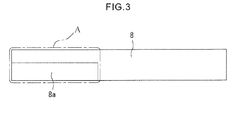
- the region having the aluminum member 8a in the case where the aluminum member 8a is formed in the left half of the front surface of the conductor for connecting terminals 8, as shown in Fig. 3 , that region includes not only the aluminum member 8a but also a part including copper or nickel in the left half on the back surface, as shown by a region A surrounded by one-dot chain line.
- the part except for the region A that is, the right halves of the front and back surfaces of the conductor for connecting terminals 8 may be brought in contact with the negative-electrode terminal 4 and welded thereto.
- the shape of the conductor for connecting terminals 8 is not limited to the flat plate and may be formed into any shape, depending on the arrangement of the electrode terminals 1 and 4 to be connected.
- the conductor for connecting terminals 8 may be bent into a crank shape. With this conductor for connecting terminals 8, even when a distance between the positive-electrode terminal 1 and the negative-electrode terminal 4 of the non-aqueous electrolyte secondary batteries 7 and 7 is long in the front-back direction, in the assembled battery according to the present embodiment, it is not necessary to further increase the thickness of the conductor for connecting terminals 8.
- the conductor for connecting terminals 8 may be bent into a dogleg shape, or one or a whole part of the conductor for connecting terminals 8 may be curved so as to correspond to the arrangement of the electrode terminals 1 and 4.
- the conductor for connecting terminals 8 includes the clad material in the above embodiment, the conductor for connecting terminals 8 is not limited to the one including the clad material.
- the conductor for connecting terminals 8 may be produced by attaching two kinds of metals by a step different from the step of producing the clad material.
- a part of one surface of a plate material including copper or nickel used for the conductor for connecting terminals 8 is notched by a machining process, and the aluminum member 8a is formed by fitting a plate material including aluminum or an aluminum alloy in this notched part and jointing the plate material thereto by welding or brazing, or by plating with aluminum or aluminum alloy.
- the conductor for connecting terminals 8 of the present invention may be formed so that the first region I projects from the surface of the second region II, or the first region I is concaved from the surface of the second region II.
- the conductor for connecting terminals 8 may be formed such that the aluminum member 8a in the shape of a smaller flat plate including aluminum or aluminum alloy and is attached to a part of a surface of a flat plate including copper or nickel.
- the conductor for connecting terminals 8 may be used for connecting the positive-electrode terminal 1 of the non-aqueous electrolyte secondary battery 7 serving as the external terminal in the assembled battery, or the positive-electrode terminal 1 of the non-aqueous electrolyte secondary battery 7 used alone, to a terminal of an external device.
- the conductor for connecting terminals 8 bent into the dogleg shape as shown in Fig. 4B may be used.
- the negative-electrode terminal 4 includes copper or copper alloy
- it may include nickel or a nickel alloy, iron, steel, stainless steel, or chrome molybdenum steel in the non-aqueous electrolyte secondary battery 7 in some cases.
- Nickel or nickel alloy, iron or steel, or stainless steel or chrome molybdenum steel has a melting point higher than that of aluminum or aluminum alloy, similarly to copper or copper alloy.
- the part of the conductor for connecting terminals 8 other than the aluminum member 8a may include the copper alloy, nickel alloy, iron, steel, stainless steel, or chrome molybdenum steel and the like. That is, the part of the conductor for connecting terminals 8 other than the aluminum member 8a may include any kind of material as long as the metal material has a melting point higher than that of aluminum or aluminum alloy. Furthermore, the material may be a composite material provided by plating copper with nickel, instead of the single metal material. Still furthermore, the electrode terminals 1 and 4 may include a plated composite material, instead of the single metal material.
- the TIG method may be used instead of the resistance welding method.
- the conductor for connecting terminals according to the present invention employs the configuration provided by overlapping, with each other, at least a plate-shaped part including a first metal and a plate-shaped part including a second metal having a melting point higher than that of the first metal.
- the conductor for connecting terminals according to the present invention may employ the configuration in which the plate-shaped part including the first metal is attached to the plate-shaped part including the second metal having the melting point higher than that of the first metal, or the configuration in which the plated layer of the first metal is formed on the plate-shaped part including the second metal having the melting point higher than that of the first metal.
- the configuration may be such that a layer is formed by evaporating the first metal, instead of the plated layer.
- the plated layer or the evaporated layer also becomes the thin plate-shaped part.
- the plate-shaped part preferably has a structure having a pair of surfaces having almost the same thickness, such as a structure having a pair of roughly parallel surfaces which are vertical in a thickness direction because the general-purpose plate material available in the market may be preferably used.
- the conductor for connecting terminals according to the present invention has only to include at least the plate-shaped part including the first metal, and the plate-shaped part including the second metal having the melting point higher than that of the first metal, so that even when the plurality of plate-shaped parts are stacked on each other, the same effect may be provided.
- the above configuration may be exemplified by the configuration in which aluminum/aluminum/copper, or aluminum/copper/copper are laminated in this order.
- FIG. 5 shows one example of such configuration.
- a conductor for connecting terminals is provided by laminating a plate-shaped part 2a including the first metal, a plate-shaped part 2b including the second metal having a melting point higher than that of the first metal, and a plate-shaped part 3 including the second metal in this order.
- An aluminum plate material is used for the plate-shaped part 2a including the first metal.
- a copper or nickel plate material is used for the plate-shaped part 2b including the second metal.
- a copper or nickel plate material having a size larger than the plate-shaped part 2b is used for the plate-shaped part 3 including the second metal.
- the conductor for connecting terminals has only to have the structure in which at least the plate-shaped part including the first metal and the plate-shaped part including the second metal having the melting point higher than that of the first metal are overlapped with each other, so that one or more plate-shaped parts including a third metal having a melting point higher than that of the first metal may be stacked on each other.
- either one of the plate-shaped parts 2b or 3 including the second metal may include the third metal.
- the conductor for connecting terminals may be provided by overlapping aluminum (2a)/nickel (2b)/copper (3) in this order.
- the number of plate-shaped part including the first metal and the number of the plate-shaped part including the second metal having the melting point higher than that of the first metal are each preferably one. This is because the present invention may be realized with the simple structure at low production cost.
- the conductor for connecting terminals of the present invention is preferably provided such that the plate-shaped part including the second metal includes a pair of flat surfaces having the same thickness, a pair of bent flat surfaces having the same thickness, or a pair of curved surfaces having the same thickness, the plate-shaped part including the first metal is laminated on one part of one surface of the pair of surfaces, and the second metal is exposed to the other part thereof.
- the second metal having the high melting point may be designed to be arranged all over the conductor for connecting terminals.
- the metal plate material having the high melting point is arranged all over the conductor for connecting terminals in the longitudinal direction, endurance of the conductor for connecting terminals against external shock may be considerably improved.
- the conductor for connecting terminals may be constituted simply at low cost with the one plate-shaped part including the second metal and the one plate-shaped part including the first metal.
- the conductor for connecting terminals of the present invention preferably includes the clad material provided by attaching the plate-shaped part including the first metal and the plate-shaped part including the second metal to each other.
- connection strength between the two metals is improved, and electric resistance may be small.
- the one region I having the exposed first metal, and the second region II having the exposed second metal are formed on the one surface, they may be preferably welded to the two terminals having the different melting points, on the same surface, respectively.
- the positive-electrode terminal to be connected includes aluminum
- the negative-electrode terminal to be connected includes copper
- the positive-electrode terminal may be welded to the first region I
- the negative-electrode terminal may be welded to the second region II or its back surface, of the conductor for connecting terminals.
- the terminal (such as the negative-electrode terminal of the non-aqueous electrolyte secondary battery or the terminal of the external device) including the metal having the same high melting point as that of the second metal may be welded to the above region well. That is, the present invention solves the problem that the aluminum member melts first, which conventionally occurs when the welding target sandwiched by the welding heads is welded by the resistance welding.
- the conductor for connecting terminals of the present invention is constituted such that there is substantially no step difference in the thickness direction at the boundary between the first region I and the second region II.
- the aluminum member 8a of the conductor for connecting terminals 8 is formed on one part of the one surface of the conductor for connecting terminals 8 so as to be flush with this surface. This configuration may effectively prevent deterioration due to the electric corrosion.
- This configuration may be realized by the method such as the method in which the aluminum member is buried in the one part of the conductor for connecting terminals so as to be flush with this part, or the method in which the aluminum member is formed by plating.
- this configuration may be obtained in such a manner that the metal plate including the first metal and the metal plate including the second metal having the melting point higher than that of the first metal are subjected to a cladding process under the condition that the former plate size is made smaller.
- a step difference is generated when the plates are simply attached to each other, but the step difference at the interface between the two metals may be substantially eliminated by the cladding process.
- the configuration in which the step difference does not substantially exist may be realized by cladding the metal plate including the first metal and the metal plate including the second metal having the same size, and thereafter removing a part of the metal plate including the first metal by a cutting process and the like performed in such a manner that at least the boundary between the first metal and the second metal is formed on an inclined surface.
- the part from which the first metal is removed to expose the second metal functions as the second region II.
- the processing method may be a chemical processing method as well as the mechanical cutting method.
- the configuration substantially having substantially no step difference may be also realized by notching one part of the surface of the metal plate including the second metal by machining process, fitting the metal plate including the first metal in this notched part, and thereafter performing the cladding process.
- an inevitably generated step difference is at such a level that is generated in the above clad material, the effect of suppressing the electric corrosion may be sufficiently obtained.
- the assembled battery of the present invention includes the battery provided with the battery exterior case, and the positive-electrode terminal and the negative-electrode terminal which project upward from the battery exterior case.
- the positive-electrode terminal and the negative-electrode terminal are formed so as to project from the battery case in the same direction, a mechanical structure to connect the batteries to each other may be gathered to an upper space of the batteries, so that the assembled battery may be compactly designed.
- the battery exterior case preferably has a structure in which a cylindrical side wall part is provided, and its opening parts at both ends are sealed with a bottom plate and a lid plate with a view to preventing deformation due to rise in internal pressure, and the side wall part may have a quadrangular prism shape having a rectangular box as a whole, a cylinder shape having a cross-section of a true circle, ellipse, or oval, or a shape similar to those.
- the battery exterior case is made of a material which is strong enough to prevent the deformation due to the rise in internal pressure, and it is preferably made of metal. As a typical material, stainless steel may be preferably used.
- the battery exterior case includes the battery container and the lid plate.
- the battery container includes the cylindrical side wall part and the bottom plate arranged in the one opening part.
- the positive-electrode terminal and the negative-electrode terminal may be provided in the lid plate. These terminals are provided in the direction projecting upward from the battery case.
- At least two batteries are arranged in the front-back direction such that the largest side surfaces of the battery containers are opposed.
- the batteries may be easily fixed.
- one or both of the positive-electrode terminal and the negative-electrode terminal of the battery are preferably in the shape of the plate.
- the conductors for connecting terminals may be configured to be arranged between the positive-electrode terminals and the negative-electrode terminals in the front-back direction.
- a contact area between each terminal and the conductor for connecting terminals may be largely ensured. This effect may be provided even when the thickness of the plate-shaped terminal decreases, so that the sufficient welding area may be maintained even when the battery is further thinned.
- the assembled battery of the present invention is provided with the conductor for connecting terminals formed in such a manner that the plate-shaped part including the first metal and the plate-shaped part including the second metal having the melting point higher than that of the first metal are overlapped with each other, the first region having the exposed first metal and the second region having the exposed second metal are formed on the one surface, and the second metal is exposed to the region opposed to the second region, in the other surface, so that the good welding may be performed to the two terminals having the different melting points.
- the non-aqueous electrolyte battery may be used as the above assembled battery.
- the batteries are arranged such that the largest area side surfaces of the side surfaces of the battery containers are opposed to each other, the conductor for connecting terminals is arranged between the terminal of the one battery and the terminal of the other battery, the first region of the conductor for connecting terminals is connected to the opposed surface of the terminal of the one battery, and the second region or the region opposed to the second region in the other surface is connected to the opposed surface of the terminal of the other battery.
- the welding between the conductor for connecting terminals and the two terminals may be easily performed, and as for both terminals having the different melting points, both terminals may be strongly and surely connected to the conductor for connecting terminals by the resistance welding method.
- a thickness of the battery container of at least one battery is preferably 1 cm or less, and more preferably 5 mm or less. This is because when the thickness is as small as 1 cm or less, temperature control of the battery may be precisely performed. When the thickness is as small as 5 mm or less, more precise control may be implemented.
- the conductor for connecting terminals used for connecting the terminals is formed such that at least the plate-shaped part including the first metal and the plate-shaped part including the second metal having the melting point higher than that of the first metal are overlapped with each other, the first region having the exposed first metal and the second region having the exposed second metal are formed on the one surface, and the second metal is exposed to the region opposed to the second region, in the other surface.
- the steps of connecting the terminals may be realized with the small number of steps as compared with the conventional one.
- the method for producing the assembled battery of the present invention goes through the step of arranging the above-described conductor for connecting terminals and the terminal of the battery such that the first region I comes in contact with the terminal of the battery, arranging the pair of welding heads so as to sandwich the terminal of the battery and the conductor for connecting terminals, and applying a current from the welding head to the conductor for connecting terminals and the terminal of the battery.
- the terminal of the battery connected in this step preferably includes the metal having the same low melting point as the first metal.
- the method goes through the step of arranging the conductor for connecting terminals and the terminal of the other battery such that the second region or the region opposed to the second region, in the other surface comes in contact with the terminal of the other battery, arranging the pair of welding heads so as to sandwich the terminal of the other battery and the conductor for connecting terminals, and applying a current from the welding head to the conductor for connecting terminals and the terminal of the other battery.
- the terminal of the battery connected in this step preferably includes the metal having the same high melting point as the second metal.
- the conductor for connecting terminals and both terminals may be preferably connected by one welding operation.
- the battery having the battery exterior case having a thickness smaller than its width and height may be preferably used.
- a battery in the shape of a rectangular box having a thickness of 1 cm or less or 5 mm or less may be used.
- the positive-electrode terminal and the negative-electrode terminal of the battery are preferably provided on the upper end side of the battery exterior case, and have the plate shape. With this configuration, a contact area between each terminal and the conductor for connecting terminals may n be large, and a sufficient welding area may be maintained even when the battery is thinned.
- the conductor for connecting terminals of the present invention may be used as the conductor for connecting terminals.
- a vehicle of the present invention includes the assembled battery of the present invention in which the conductor for connecting terminals and the terminal of the battery are strongly welded, so that the highly-reliable vehicle which is superior in vibration resistance may be provided.
- good cooling performance may be realized due to the thinner battery, and as a result, the battery may be mounted as the assembled battery having high capacity, so that the vehicle may ensure a sufficient driving distance. More specifically, the thickness of the battery in the assembled battery may be 1 cm or less, or more preferably, 5 mm or less.
- the assembled battery may be used as a power supply to supply electricity to a driving motor, or may be used as a power supply of a starter motor of a driving power engine.
- the power engine includes a gasoline engine, diesel engine, and hydrogen-fueled engine, etc. When the vehicle has both driving motor and power engine, electricity may be supplied to both of them.
- a DC motor may be used as the starter motor.
- the vehicle of the present invention preferably includes a charging apparatus to charge the assembled battery.
- the charging apparatus converts mechanical kinetic energy transmitted from the driving motor or the driving power engine, to electric energy, and it is preferably configured to charge the assembled battery by converting an AC current obtained by the power generating apparatus to a DC current.
- the vehicle of the present invention may include a tire, a wheel, and a instrument including a sensor for vehicle speed, and may include a clutch and an axle to transmit the power from the driving motor or the power engine to the tires or wheels.
- the battery connecting structure and the assembled battery using the structure according to the present invention may realize the easy and compact welding for connecting and fixing the terminals of the batteries with the conductor for connecting terminals, and are thus extremely useful.
- the present invention is extremely useful in that the assembled battery superior in welding strength may be provided with the thin battery.
Landscapes
- Chemical & Material Sciences (AREA)
- Chemical Kinetics & Catalysis (AREA)
- Electrochemistry (AREA)
- General Chemical & Material Sciences (AREA)
- Inorganic Chemistry (AREA)
- Engineering & Computer Science (AREA)
- Manufacturing & Machinery (AREA)
- Connection Of Batteries Or Terminals (AREA)
- Battery Mounting, Suspending (AREA)
- Sealing Battery Cases Or Jackets (AREA)
Applications Claiming Priority (2)
| Application Number | Priority Date | Filing Date | Title |
|---|---|---|---|
| JP2009021690 | 2009-02-02 | ||
| PCT/JP2010/051333 WO2010087472A1 (fr) | 2009-02-02 | 2010-02-01 | Conducteur de connexion de bornes, batterie assemblée et procédé de fabrication d'une batterie assemblée |
Publications (3)
| Publication Number | Publication Date |
|---|---|
| EP2393144A1 true EP2393144A1 (fr) | 2011-12-07 |
| EP2393144A4 EP2393144A4 (fr) | 2016-08-03 |
| EP2393144B1 EP2393144B1 (fr) | 2019-05-22 |
Family
ID=42395724
Family Applications (1)
| Application Number | Title | Priority Date | Filing Date |
|---|---|---|---|
| EP10735932.5A Active EP2393144B1 (fr) | 2009-02-02 | 2010-02-01 | Conducteur de connexion de bornes, batterie assemblée et procédé de fabrication d'une batterie assemblée |
Country Status (7)
| Country | Link |
|---|---|
| US (1) | US9017858B2 (fr) |
| EP (1) | EP2393144B1 (fr) |
| JP (2) | JP5601203B2 (fr) |
| KR (3) | KR101495586B1 (fr) |
| CN (4) | CN103762330B (fr) |
| TW (1) | TW201042859A (fr) |
| WO (1) | WO2010087472A1 (fr) |
Cited By (9)
| Publication number | Priority date | Publication date | Assignee | Title |
|---|---|---|---|---|
| WO2013051012A3 (fr) * | 2011-06-06 | 2013-06-13 | Tata Motors Limited | Dispositif de barre omnibus bimétallique pour ensembles d'éléments de batterie |
| WO2013176914A1 (fr) * | 2012-05-21 | 2013-11-28 | Tyco Electronics Corporation | Ensemble barre omnibus bimétallique |
| EP2736097A3 (fr) * | 2012-11-23 | 2014-07-02 | Samsung SDI Co., Ltd. | Batterie rechargeable et son module |
| EP2899778A1 (fr) * | 2014-01-28 | 2015-07-29 | Samsung SDI Co., Ltd. | Bloc-batteries |
| US9136617B2 (en) | 2010-10-15 | 2015-09-15 | Kobe Steel, Ltd. | Battery connector formed of plural materials, and production method |
| WO2020041764A1 (fr) * | 2018-08-23 | 2020-02-27 | Rivian Ip Holdings, Llc | Barres omnibus dotées de liaisons fusibles intégrées et estampées |
| US10944090B2 (en) | 2018-08-23 | 2021-03-09 | Rivian Ip Holdings, Llc | Layered busbars having integrated fusible links |
| US10957892B2 (en) | 2018-08-23 | 2021-03-23 | Rivian Ip Holdings, Llc | Busbars having stamped fusible links |
| WO2023156203A1 (fr) * | 2022-02-15 | 2023-08-24 | Diehl Advanced Mobility GmbH | Système de mise en contact d'éléments |
Families Citing this family (52)
| Publication number | Priority date | Publication date | Assignee | Title |
|---|---|---|---|---|
| JP5528746B2 (ja) * | 2009-09-11 | 2014-06-25 | 三洋電機株式会社 | 組電池 |
| JP5731836B2 (ja) * | 2010-03-15 | 2015-06-10 | セイコーインスツル株式会社 | 端子付電気化学セルとその製造方法 |
| DE102010029970B4 (de) * | 2010-06-11 | 2021-06-02 | Vitesco Technologies GmbH | Batterie mit passivem Korrosionsschutz |
| CN103069613B (zh) * | 2010-12-28 | 2014-04-02 | 株式会社新王材料 | 电池端子用连接板和电池端子用连接板的制造方法 |
| JPWO2012118014A1 (ja) * | 2011-02-28 | 2014-07-07 | 三洋電機株式会社 | バッテリシステム及びバッテリシステムを備える車両 |
| JP5976634B2 (ja) * | 2011-03-29 | 2016-08-23 | 三洋電機株式会社 | 電源装置及び電源装置を備える車両 |
| JP5965396B2 (ja) * | 2011-06-02 | 2016-08-03 | 株式会社日立金属ネオマテリアル | 電池用負極端子および電池用負極端子の製造方法 |
| JP5840207B2 (ja) * | 2011-06-10 | 2016-01-06 | 日立オートモティブシステムズ株式会社 | 二次電池 |
| WO2013001644A1 (fr) * | 2011-06-30 | 2013-01-03 | 日立ビークルエナジー株式会社 | Batterie assemblée |
| US9017871B2 (en) | 2011-08-04 | 2015-04-28 | Neomax Materials Co., Ltd. | Negative-electrode terminal for cell |
| JP6023416B2 (ja) * | 2011-10-19 | 2016-11-09 | 矢崎総業株式会社 | 電源装置 |
| US20130101892A1 (en) * | 2011-10-19 | 2013-04-25 | Cobasys, Llc | Fusible link to connect battery cells and modules |
| JP5530464B2 (ja) * | 2012-01-11 | 2014-06-25 | トヨタ自動車株式会社 | パワーコントロールユニット用バスバー |
| DE102012020415A1 (de) * | 2012-10-12 | 2014-04-17 | Dynamis Holding AG | Wiederaufladbares Stromspeichermodul |
| US20140134473A1 (en) * | 2012-11-14 | 2014-05-15 | General Electric Company | Electrical interconnect and method of assembling a rechargeable battery |
| US20140134471A1 (en) * | 2012-11-14 | 2014-05-15 | General Electric Company | Electrical interconnect and method of assembling a rechargeable battery |
| JP5985993B2 (ja) * | 2013-01-10 | 2016-09-06 | 日立オートモティブシステムズ株式会社 | 組電池及びその製造方法 |
| JP5985992B2 (ja) * | 2013-01-10 | 2016-09-06 | 日立オートモティブシステムズ株式会社 | 角形二次電池及びその製造方法、並びに角形二次電池の外部端子にバスバーを接合する方法 |
| JP6114098B2 (ja) * | 2013-04-22 | 2017-04-12 | 矢崎総業株式会社 | 電源装置 |
| WO2014178114A1 (fr) * | 2013-04-30 | 2014-11-06 | 日立オートモティブシステムズ株式会社 | Barre omnibus de batterie assemblée et batterie assemblée |
| JP5957651B2 (ja) * | 2013-06-07 | 2016-07-27 | パナソニックIpマネジメント株式会社 | 組電池 |
| JP6026961B2 (ja) * | 2013-06-18 | 2016-11-16 | 豊田合成株式会社 | 電池セル、電池ユニットおよび電池スタック |
| KR20150015153A (ko) * | 2013-07-31 | 2015-02-10 | 주식회사 엘지화학 | 이종 금속의 전지모듈 접속부재를 포함하는 전지팩 |
| US9660244B2 (en) | 2013-09-06 | 2017-05-23 | Johnson Controls Technology Company | System and method for establishing connections of a battery module |
| JP6385426B2 (ja) * | 2014-03-25 | 2018-09-05 | 旭化成株式会社 | 電池の正負電極端子接続部材 |
| EP3159953B1 (fr) | 2014-06-18 | 2019-08-14 | Nissan Motor Co., Ltd | Procédé de soudage de languette de bloc-batterie |
| DE102015210631A1 (de) * | 2015-06-10 | 2016-12-15 | Robert Bosch Gmbh | Batteriezelle und Verfahren zum Verbinden von Batteriezellen sowie Batteriepack, Batteriemodul, Batterie und Fahrzeug |
| JP6590212B2 (ja) * | 2015-07-17 | 2019-10-16 | 株式会社オートネットワーク技術研究所 | 配線モジュール、及び蓄電モジュール |
| KR102468334B1 (ko) * | 2015-11-04 | 2022-11-16 | 삼성에스디아이 주식회사 | 이차 전지 모듈 |
| WO2017175362A1 (fr) * | 2016-04-07 | 2017-10-12 | Connexx Systems株式会社 | Batterie assemblée en forme de plaque |
| CN105845881A (zh) * | 2016-05-20 | 2016-08-10 | 惠州市亿鹏能源科技有限公司 | 一种动力电池电源模块连接结构 |
| WO2018155090A1 (fr) * | 2017-02-27 | 2018-08-30 | 日立オートモティブシステムズ株式会社 | Bloc-batterie et barre omnibus pour bloc-batterie |
| KR102187067B1 (ko) | 2017-08-10 | 2020-12-04 | 주식회사 엘지화학 | 배터리 모듈 및 배터리 모듈의 제조 방법 |
| KR102428417B1 (ko) * | 2017-10-11 | 2022-08-01 | 주식회사 엘지에너지솔루션 | 전지 모듈 및 이의 제조 방법 |
| JP7190821B2 (ja) * | 2018-04-18 | 2022-12-16 | 河村電器産業株式会社 | 蓄電装置 |
| JP6904299B2 (ja) * | 2018-04-19 | 2021-07-14 | トヨタ自動車株式会社 | 積層電池の製造方法 |
| US11831030B2 (en) | 2018-05-22 | 2023-11-28 | Pacesetter, Inc. | Method of forming a brazed joint having molybdenum material |
| US20200091493A1 (en) * | 2018-09-19 | 2020-03-19 | Tiveni Mergeco, Inc. | Battery module including coated or clad material contact plate |
| WO2020183817A1 (fr) * | 2019-03-12 | 2020-09-17 | ビークルエナジージャパン株式会社 | Barre omnibus et module de batteries l'utilisant |
| CN113363634B (zh) * | 2019-05-15 | 2023-08-04 | 广东微电新能源有限公司 | 纽扣型电池及其制造方法 |
| TWI729548B (zh) * | 2019-10-31 | 2021-06-01 | 希世比能源科技股份有限公司 | 電池裝置 |
| KR102773242B1 (ko) * | 2020-04-07 | 2025-02-27 | 주식회사 엘지에너지솔루션 | 이종금속으로 이루어진 전극 리드 및 이의 제조 방법 |
| JP7615454B2 (ja) * | 2020-06-19 | 2025-01-17 | トヨタ自動車株式会社 | 積層型電池 |
| CN113889713B (zh) * | 2020-07-03 | 2024-10-25 | 莫仕连接器(成都)有限公司 | 电池连接模块 |
| JP7373523B2 (ja) * | 2021-05-20 | 2023-11-02 | プライムプラネットエナジー&ソリューションズ株式会社 | 端子、二次電池および端子の製造方法 |
| EP4152512A4 (fr) | 2021-07-30 | 2023-11-08 | Contemporary Amperex Technology Co., Limited | Batterie, dispositif électrique et procédé de préparation de batterie |
| CN118104062A (zh) * | 2021-11-15 | 2024-05-28 | 日本汽车能源株式会社 | 组合电池 |
| JP2023142497A (ja) * | 2022-03-25 | 2023-10-05 | 株式会社プロテリアル | 導電接続部品および導電接続構造 |
| CN114824593B (zh) * | 2022-05-25 | 2024-05-17 | 东莞新能德科技有限公司 | 电化学装置以及用电设备 |
| CN117117437B (zh) * | 2023-10-11 | 2026-01-27 | 珠海格力电器股份有限公司 | 电池组及冰箱 |
| CN118763438B (zh) * | 2024-07-08 | 2025-11-28 | 昆宇电源股份有限公司 | 一种可将电池组向上进行容量兼容的端子座 |
| CN223156240U (zh) * | 2024-08-14 | 2025-07-25 | 宁德时代新能源科技股份有限公司 | 电池单体、电池装置、用电装置及储能装置 |
Family Cites Families (20)
| Publication number | Priority date | Publication date | Assignee | Title |
|---|---|---|---|---|
| US3882265A (en) * | 1974-05-03 | 1975-05-06 | Gen Electric | Electrical busway with improved joint construction |
| JPH0353416Y2 (fr) * | 1984-09-13 | 1991-11-21 | ||
| JPH0992262A (ja) * | 1995-09-27 | 1997-04-04 | Shin Kobe Electric Mach Co Ltd | 鉛蓄電池の組電池 |
| JP3675954B2 (ja) | 1996-06-10 | 2005-07-27 | 三洋電機株式会社 | リード板付き電池 |
| JP2000036299A (ja) * | 1998-07-17 | 2000-02-02 | Japan Storage Battery Co Ltd | 電池用の端子接続板 |
| US6844110B2 (en) * | 2000-05-24 | 2005-01-18 | Ngk Insulators, Ltd. | Lithium secondary cell and assembly thereof |
| JP2002075324A (ja) * | 2000-09-04 | 2002-03-15 | Mitsubishi Chemicals Corp | 電 池 |
| JP5034137B2 (ja) * | 2000-11-01 | 2012-09-26 | ソニー株式会社 | 溶接物の製造方法,台座および電池の製造方法 |
| JP2002151045A (ja) | 2000-11-10 | 2002-05-24 | Honda Motor Co Ltd | 電池モジュール用バスバーおよび電池モジュール |
| JP2002358945A (ja) * | 2000-11-15 | 2002-12-13 | Ngk Insulators Ltd | リチウム二次単電池の接続構造体 |
| JP4204237B2 (ja) | 2001-03-21 | 2009-01-07 | 日本碍子株式会社 | リチウム二次単電池およびリチウム二次単電池の接続構造体 |
| JP2003123733A (ja) * | 2001-10-18 | 2003-04-25 | Sony Corp | 電池用電極及びリチウムイオンポリマ電池、並びにそれらの製造方法 |
| JP3829086B2 (ja) * | 2001-11-12 | 2006-10-04 | 松下電器産業株式会社 | 非水電解液電池およびその製造方法 |
| JP4380163B2 (ja) * | 2003-01-23 | 2009-12-09 | ソニー株式会社 | リード端子及び電源装置 |
| JP4527366B2 (ja) * | 2003-05-30 | 2010-08-18 | セイコーインスツル株式会社 | 電気化学セルの製造方法 |
| WO2006016441A1 (fr) * | 2004-08-09 | 2006-02-16 | Nec Corporation | Méthode de soudure de fines plaques de différents métaux, corps jointif de fines plaques de différents métaux, le dispositif électrique et le montage électrique du dispositif |
| JP2007280898A (ja) * | 2006-04-12 | 2007-10-25 | Toyota Motor Corp | 端子接続構造および蓄電機構ならびに電動車両 |
| JP5078282B2 (ja) * | 2006-05-31 | 2012-11-21 | 三洋電機株式会社 | 組電池 |
| JP4764290B2 (ja) * | 2006-08-31 | 2011-08-31 | ダイヤモンド電機株式会社 | 導電端子のメッキ構造及びこれを用いる内燃機関の点火装置 |
| US9196890B2 (en) * | 2009-10-05 | 2015-11-24 | Samsung Sdi Co., Ltd. | Battery module with welded portion between terminals |
-
2010
- 2010-02-01 CN CN201310704135.1A patent/CN103762330B/zh not_active Expired - Fee Related
- 2010-02-01 TW TW099102823A patent/TW201042859A/zh unknown
- 2010-02-01 CN CN201310704141.7A patent/CN103762331B/zh not_active Expired - Fee Related
- 2010-02-01 KR KR1020147007580A patent/KR101495586B1/ko active Active
- 2010-02-01 KR KR1020117011571A patent/KR101280344B1/ko active Active
- 2010-02-01 KR KR1020137010796A patent/KR20130054449A/ko not_active Ceased
- 2010-02-01 CN CN201080003650.1A patent/CN102265430B/zh active Active
- 2010-02-01 CN CN201310703612.2A patent/CN103762329B/zh not_active Expired - Fee Related
- 2010-02-01 EP EP10735932.5A patent/EP2393144B1/fr active Active
- 2010-02-01 JP JP2010548583A patent/JP5601203B2/ja active Active
- 2010-02-01 US US13/138,327 patent/US9017858B2/en active Active
- 2010-02-01 WO PCT/JP2010/051333 patent/WO2010087472A1/fr not_active Ceased
-
2014
- 2014-08-18 JP JP2014165650A patent/JP2015008146A/ja active Pending
Non-Patent Citations (1)
| Title |
|---|
| See references of WO2010087472A1 * |
Cited By (15)
| Publication number | Priority date | Publication date | Assignee | Title |
|---|---|---|---|---|
| EP2581966B1 (fr) * | 2010-10-15 | 2016-08-31 | Kabushiki Kaisha Kobe Seiko Sho (Kobe Steel, Ltd.) | Élément de connexion conducteur de l'électricité, procédé de fabrication d'élément de connexion conducteur de l'électricité et batterie équipée de l'élément de connexion conducteur de l'électricité en tant qu'électrode |
| US9136617B2 (en) | 2010-10-15 | 2015-09-15 | Kobe Steel, Ltd. | Battery connector formed of plural materials, and production method |
| WO2013051012A3 (fr) * | 2011-06-06 | 2013-06-13 | Tata Motors Limited | Dispositif de barre omnibus bimétallique pour ensembles d'éléments de batterie |
| WO2013176914A1 (fr) * | 2012-05-21 | 2013-11-28 | Tyco Electronics Corporation | Ensemble barre omnibus bimétallique |
| US9318734B2 (en) | 2012-05-21 | 2016-04-19 | Tyco Electronics Corporation | Bimetal buss bar assembly |
| EP2736097A3 (fr) * | 2012-11-23 | 2014-07-02 | Samsung SDI Co., Ltd. | Batterie rechargeable et son module |
| US9142823B2 (en) | 2012-11-23 | 2015-09-22 | Samsung Sdi Co., Ltd. | Rechargeable battery and module of the same |
| EP2899778A1 (fr) * | 2014-01-28 | 2015-07-29 | Samsung SDI Co., Ltd. | Bloc-batteries |
| US9484566B2 (en) | 2014-01-28 | 2016-11-01 | Samsung Sdi Co., Ltd. | Battery pack |
| WO2020041764A1 (fr) * | 2018-08-23 | 2020-02-27 | Rivian Ip Holdings, Llc | Barres omnibus dotées de liaisons fusibles intégrées et estampées |
| US10944090B2 (en) | 2018-08-23 | 2021-03-09 | Rivian Ip Holdings, Llc | Layered busbars having integrated fusible links |
| US10957892B2 (en) | 2018-08-23 | 2021-03-23 | Rivian Ip Holdings, Llc | Busbars having stamped fusible links |
| US11749869B2 (en) | 2018-08-23 | 2023-09-05 | Rivian Ip Holdings, Llc | Busbars having stamped fusible links |
| US11984621B2 (en) | 2018-08-23 | 2024-05-14 | Rivian Ip Holdings, Llc | Busbars having stamped fusible links |
| WO2023156203A1 (fr) * | 2022-02-15 | 2023-08-24 | Diehl Advanced Mobility GmbH | Système de mise en contact d'éléments |
Also Published As
| Publication number | Publication date |
|---|---|
| JP2015008146A (ja) | 2015-01-15 |
| CN102265430A (zh) | 2011-11-30 |
| CN103762330A (zh) | 2014-04-30 |
| WO2010087472A1 (fr) | 2010-08-05 |
| CN102265430B (zh) | 2014-07-30 |
| KR101495586B1 (ko) | 2015-02-25 |
| EP2393144A4 (fr) | 2016-08-03 |
| CN103762331B (zh) | 2016-03-02 |
| US20110293995A1 (en) | 2011-12-01 |
| US9017858B2 (en) | 2015-04-28 |
| KR20130054449A (ko) | 2013-05-24 |
| KR101280344B1 (ko) | 2013-07-01 |
| CN103762329A (zh) | 2014-04-30 |
| KR20110081860A (ko) | 2011-07-14 |
| CN103762331A (zh) | 2014-04-30 |
| CN103762329B (zh) | 2016-04-13 |
| CN103762330B (zh) | 2016-04-13 |
| TW201042859A (en) | 2010-12-01 |
| JP5601203B2 (ja) | 2014-10-08 |
| JPWO2010087472A1 (ja) | 2012-08-02 |
| EP2393144B1 (fr) | 2019-05-22 |
| KR20140043506A (ko) | 2014-04-09 |
Similar Documents
| Publication | Publication Date | Title |
|---|---|---|
| US9017858B2 (en) | Conductor for connecting terminals comprising plate-shaped parts, assembled battery, and method for producing assembled battery | |
| EP2378593B1 (fr) | Module de batterie | |
| US11374290B2 (en) | Power supply device, vehicle in which same is used, and bus bar | |
| EP3243232B1 (fr) | Plans de soudage séparés pour module de batterie | |
| EP3664181B1 (fr) | Batterie rechargeable cylindrique ayant une structure destinée à protéger contre un faisceau laser pour un soudage, et bloc-batterie comprenant cette dernière | |
| CN106025119B (zh) | 方形二次电池 | |
| US20140242440A1 (en) | Prismatic secondary battery | |
| CN107665968B (zh) | 二次电池及其制造方法、以及使用该二次电池的组电池 | |
| US20240170809A1 (en) | Tab welding method, welding tool, battery cell, battery, and electric device | |
| US7943253B2 (en) | Sealed battery and manufacturing method therefor | |
| US9147865B2 (en) | System and method for closing a battery fill hole | |
| EP4510316A1 (fr) | Boîtier, cellule de batterie, batterie et dispositif électrique | |
| EP4270618A1 (fr) | Barre omnibus et bloc-batterie l'incluant | |
| EP4420820B1 (fr) | Dispositif de stockage d'énergie et module de stockage d'énergie le comprenant | |
| US20230019424A1 (en) | Horn, terminal component, and secondary battery | |
| CN118748304A (zh) | 电芯外壳、电芯焊接壳、电芯单体、电池模组及交通工具 | |
| WO2024128143A1 (fr) | Dispositif de stockage d'énergie électrique | |
| JP2025110602A (ja) | 蓄電素子 | |
| CN121175141A (zh) | 激光焊接用复合材、使用激光焊接用复合材的接合结构和电池的制造方法 |
Legal Events
| Date | Code | Title | Description |
|---|---|---|---|
| PUAI | Public reference made under article 153(3) epc to a published international application that has entered the european phase |
Free format text: ORIGINAL CODE: 0009012 |
|
| 17P | Request for examination filed |
Effective date: 20110902 |
|
| AK | Designated contracting states |
Kind code of ref document: A1 Designated state(s): AT BE BG CH CY CZ DE DK EE ES FI FR GB GR HR HU IE IS IT LI LT LU LV MC MK MT NL NO PL PT RO SE SI SK SM TR |
|
| DAX | Request for extension of the european patent (deleted) | ||
| RA4 | Supplementary search report drawn up and despatched (corrected) |
Effective date: 20160704 |
|
| RIC1 | Information provided on ipc code assigned before grant |
Ipc: H01M 2/30 20060101ALN20160628BHEP Ipc: H01M 2/20 20060101AFI20160628BHEP Ipc: H01M 10/05 20100101ALN20160628BHEP Ipc: H01M 10/058 20100101ALN20160628BHEP |
|
| STAA | Information on the status of an ep patent application or granted ep patent |
Free format text: STATUS: EXAMINATION IS IN PROGRESS |
|
| 17Q | First examination report despatched |
Effective date: 20171013 |
|
| GRAP | Despatch of communication of intention to grant a patent |
Free format text: ORIGINAL CODE: EPIDOSNIGR1 |
|
| STAA | Information on the status of an ep patent application or granted ep patent |
Free format text: STATUS: GRANT OF PATENT IS INTENDED |
|
| INTG | Intention to grant announced |
Effective date: 20190211 |
|
| GRAS | Grant fee paid |
Free format text: ORIGINAL CODE: EPIDOSNIGR3 |
|
| GRAA | (expected) grant |
Free format text: ORIGINAL CODE: 0009210 |
|
| STAA | Information on the status of an ep patent application or granted ep patent |
Free format text: STATUS: THE PATENT HAS BEEN GRANTED |
|
| AK | Designated contracting states |
Kind code of ref document: B1 Designated state(s): AT BE BG CH CY CZ DE DK EE ES FI FR GB GR HR HU IE IS IT LI LT LU LV MC MK MT NL NO PL PT RO SE SI SK SM TR |
|
| REG | Reference to a national code |
Ref country code: GB Ref legal event code: FG4D |
|
| REG | Reference to a national code |
Ref country code: CH Ref legal event code: EP |
|
| REG | Reference to a national code |
Ref country code: IE Ref legal event code: FG4D |
|
| REG | Reference to a national code |
Ref country code: DE Ref legal event code: R096 Ref document number: 602010059036 Country of ref document: DE |
|
| REG | Reference to a national code |
Ref country code: AT Ref legal event code: REF Ref document number: 1137180 Country of ref document: AT Kind code of ref document: T Effective date: 20190615 |
|
| REG | Reference to a national code |
Ref country code: NL Ref legal event code: MP Effective date: 20190522 |
|
| REG | Reference to a national code |
Ref country code: LT Ref legal event code: MG4D |
|
| PG25 | Lapsed in a contracting state [announced via postgrant information from national office to epo] |
Ref country code: SE Free format text: LAPSE BECAUSE OF FAILURE TO SUBMIT A TRANSLATION OF THE DESCRIPTION OR TO PAY THE FEE WITHIN THE PRESCRIBED TIME-LIMIT Effective date: 20190522 Ref country code: NL Free format text: LAPSE BECAUSE OF FAILURE TO SUBMIT A TRANSLATION OF THE DESCRIPTION OR TO PAY THE FEE WITHIN THE PRESCRIBED TIME-LIMIT Effective date: 20190522 Ref country code: ES Free format text: LAPSE BECAUSE OF FAILURE TO SUBMIT A TRANSLATION OF THE DESCRIPTION OR TO PAY THE FEE WITHIN THE PRESCRIBED TIME-LIMIT Effective date: 20190522 Ref country code: HR Free format text: LAPSE BECAUSE OF FAILURE TO SUBMIT A TRANSLATION OF THE DESCRIPTION OR TO PAY THE FEE WITHIN THE PRESCRIBED TIME-LIMIT Effective date: 20190522 Ref country code: NO Free format text: LAPSE BECAUSE OF FAILURE TO SUBMIT A TRANSLATION OF THE DESCRIPTION OR TO PAY THE FEE WITHIN THE PRESCRIBED TIME-LIMIT Effective date: 20190822 Ref country code: PT Free format text: LAPSE BECAUSE OF FAILURE TO SUBMIT A TRANSLATION OF THE DESCRIPTION OR TO PAY THE FEE WITHIN THE PRESCRIBED TIME-LIMIT Effective date: 20190922 Ref country code: FI Free format text: LAPSE BECAUSE OF FAILURE TO SUBMIT A TRANSLATION OF THE DESCRIPTION OR TO PAY THE FEE WITHIN THE PRESCRIBED TIME-LIMIT Effective date: 20190522 Ref country code: LT Free format text: LAPSE BECAUSE OF FAILURE TO SUBMIT A TRANSLATION OF THE DESCRIPTION OR TO PAY THE FEE WITHIN THE PRESCRIBED TIME-LIMIT Effective date: 20190522 |
|
| PG25 | Lapsed in a contracting state [announced via postgrant information from national office to epo] |
Ref country code: GR Free format text: LAPSE BECAUSE OF FAILURE TO SUBMIT A TRANSLATION OF THE DESCRIPTION OR TO PAY THE FEE WITHIN THE PRESCRIBED TIME-LIMIT Effective date: 20190823 Ref country code: BG Free format text: LAPSE BECAUSE OF FAILURE TO SUBMIT A TRANSLATION OF THE DESCRIPTION OR TO PAY THE FEE WITHIN THE PRESCRIBED TIME-LIMIT Effective date: 20190822 Ref country code: LV Free format text: LAPSE BECAUSE OF FAILURE TO SUBMIT A TRANSLATION OF THE DESCRIPTION OR TO PAY THE FEE WITHIN THE PRESCRIBED TIME-LIMIT Effective date: 20190522 |
|
| REG | Reference to a national code |
Ref country code: AT Ref legal event code: MK05 Ref document number: 1137180 Country of ref document: AT Kind code of ref document: T Effective date: 20190522 |
|
| PG25 | Lapsed in a contracting state [announced via postgrant information from national office to epo] |
Ref country code: DK Free format text: LAPSE BECAUSE OF FAILURE TO SUBMIT A TRANSLATION OF THE DESCRIPTION OR TO PAY THE FEE WITHIN THE PRESCRIBED TIME-LIMIT Effective date: 20190522 Ref country code: AT Free format text: LAPSE BECAUSE OF FAILURE TO SUBMIT A TRANSLATION OF THE DESCRIPTION OR TO PAY THE FEE WITHIN THE PRESCRIBED TIME-LIMIT Effective date: 20190522 Ref country code: EE Free format text: LAPSE BECAUSE OF FAILURE TO SUBMIT A TRANSLATION OF THE DESCRIPTION OR TO PAY THE FEE WITHIN THE PRESCRIBED TIME-LIMIT Effective date: 20190522 Ref country code: CZ Free format text: LAPSE BECAUSE OF FAILURE TO SUBMIT A TRANSLATION OF THE DESCRIPTION OR TO PAY THE FEE WITHIN THE PRESCRIBED TIME-LIMIT Effective date: 20190522 Ref country code: RO Free format text: LAPSE BECAUSE OF FAILURE TO SUBMIT A TRANSLATION OF THE DESCRIPTION OR TO PAY THE FEE WITHIN THE PRESCRIBED TIME-LIMIT Effective date: 20190522 Ref country code: SK Free format text: LAPSE BECAUSE OF FAILURE TO SUBMIT A TRANSLATION OF THE DESCRIPTION OR TO PAY THE FEE WITHIN THE PRESCRIBED TIME-LIMIT Effective date: 20190522 |
|
| REG | Reference to a national code |
Ref country code: DE Ref legal event code: R097 Ref document number: 602010059036 Country of ref document: DE |
|
| PG25 | Lapsed in a contracting state [announced via postgrant information from national office to epo] |
Ref country code: IT Free format text: LAPSE BECAUSE OF FAILURE TO SUBMIT A TRANSLATION OF THE DESCRIPTION OR TO PAY THE FEE WITHIN THE PRESCRIBED TIME-LIMIT Effective date: 20190522 Ref country code: SM Free format text: LAPSE BECAUSE OF FAILURE TO SUBMIT A TRANSLATION OF THE DESCRIPTION OR TO PAY THE FEE WITHIN THE PRESCRIBED TIME-LIMIT Effective date: 20190522 |
|
| PLBE | No opposition filed within time limit |
Free format text: ORIGINAL CODE: 0009261 |
|
| STAA | Information on the status of an ep patent application or granted ep patent |
Free format text: STATUS: NO OPPOSITION FILED WITHIN TIME LIMIT |
|
| PG25 | Lapsed in a contracting state [announced via postgrant information from national office to epo] |
Ref country code: TR Free format text: LAPSE BECAUSE OF FAILURE TO SUBMIT A TRANSLATION OF THE DESCRIPTION OR TO PAY THE FEE WITHIN THE PRESCRIBED TIME-LIMIT Effective date: 20190522 |
|
| 26N | No opposition filed |
Effective date: 20200225 |
|
| PG25 | Lapsed in a contracting state [announced via postgrant information from national office to epo] |
Ref country code: PL Free format text: LAPSE BECAUSE OF FAILURE TO SUBMIT A TRANSLATION OF THE DESCRIPTION OR TO PAY THE FEE WITHIN THE PRESCRIBED TIME-LIMIT Effective date: 20190522 |
|
| PG25 | Lapsed in a contracting state [announced via postgrant information from national office to epo] |
Ref country code: SI Free format text: LAPSE BECAUSE OF FAILURE TO SUBMIT A TRANSLATION OF THE DESCRIPTION OR TO PAY THE FEE WITHIN THE PRESCRIBED TIME-LIMIT Effective date: 20190522 |
|
| REG | Reference to a national code |
Ref country code: CH Ref legal event code: PL |
|
| GBPC | Gb: european patent ceased through non-payment of renewal fee |
Effective date: 20200201 |
|
| REG | Reference to a national code |
Ref country code: BE Ref legal event code: MM Effective date: 20200229 |
|
| PG25 | Lapsed in a contracting state [announced via postgrant information from national office to epo] |
Ref country code: MC Free format text: LAPSE BECAUSE OF FAILURE TO SUBMIT A TRANSLATION OF THE DESCRIPTION OR TO PAY THE FEE WITHIN THE PRESCRIBED TIME-LIMIT Effective date: 20190522 Ref country code: LU Free format text: LAPSE BECAUSE OF NON-PAYMENT OF DUE FEES Effective date: 20200201 |
|
| REG | Reference to a national code |
Ref country code: DE Ref legal event code: R079 Ref document number: 602010059036 Country of ref document: DE Free format text: PREVIOUS MAIN CLASS: H01M0002200000 Ipc: H01M0050500000 |
|
| PG25 | Lapsed in a contracting state [announced via postgrant information from national office to epo] |
Ref country code: LI Free format text: LAPSE BECAUSE OF NON-PAYMENT OF DUE FEES Effective date: 20200229 Ref country code: CH Free format text: LAPSE BECAUSE OF NON-PAYMENT OF DUE FEES Effective date: 20200229 |
|
| PG25 | Lapsed in a contracting state [announced via postgrant information from national office to epo] |
Ref country code: GB Free format text: LAPSE BECAUSE OF NON-PAYMENT OF DUE FEES Effective date: 20200201 Ref country code: IE Free format text: LAPSE BECAUSE OF NON-PAYMENT OF DUE FEES Effective date: 20200201 Ref country code: FR Free format text: LAPSE BECAUSE OF NON-PAYMENT OF DUE FEES Effective date: 20200229 |
|
| PG25 | Lapsed in a contracting state [announced via postgrant information from national office to epo] |
Ref country code: BE Free format text: LAPSE BECAUSE OF NON-PAYMENT OF DUE FEES Effective date: 20200229 |
|
| PG25 | Lapsed in a contracting state [announced via postgrant information from national office to epo] |
Ref country code: MT Free format text: LAPSE BECAUSE OF FAILURE TO SUBMIT A TRANSLATION OF THE DESCRIPTION OR TO PAY THE FEE WITHIN THE PRESCRIBED TIME-LIMIT Effective date: 20190522 Ref country code: CY Free format text: LAPSE BECAUSE OF FAILURE TO SUBMIT A TRANSLATION OF THE DESCRIPTION OR TO PAY THE FEE WITHIN THE PRESCRIBED TIME-LIMIT Effective date: 20190522 |
|
| PG25 | Lapsed in a contracting state [announced via postgrant information from national office to epo] |
Ref country code: MK Free format text: LAPSE BECAUSE OF FAILURE TO SUBMIT A TRANSLATION OF THE DESCRIPTION OR TO PAY THE FEE WITHIN THE PRESCRIBED TIME-LIMIT Effective date: 20190522 Ref country code: IS Free format text: LAPSE BECAUSE OF FAILURE TO SUBMIT A TRANSLATION OF THE DESCRIPTION OR TO PAY THE FEE WITHIN THE PRESCRIBED TIME-LIMIT Effective date: 20190922 |
|
| P01 | Opt-out of the competence of the unified patent court (upc) registered |
Effective date: 20230522 |
|
| PGFP | Annual fee paid to national office [announced via postgrant information from national office to epo] |
Ref country code: DE Payment date: 20260121 Year of fee payment: 17 |