EP2393456B1 - Mixer and method for mixing biphasic compounds - Google Patents
Mixer and method for mixing biphasic compounds Download PDFInfo
- Publication number
- EP2393456B1 EP2393456B1 EP20090785803 EP09785803A EP2393456B1 EP 2393456 B1 EP2393456 B1 EP 2393456B1 EP 20090785803 EP20090785803 EP 20090785803 EP 09785803 A EP09785803 A EP 09785803A EP 2393456 B1 EP2393456 B1 EP 2393456B1
- Authority
- EP
- European Patent Office
- Prior art keywords
- chamber
- mixing
- dispensing
- mixing unit
- unit
- Prior art date
- Legal status (The legal status is an assumption and is not a legal conclusion. Google has not performed a legal analysis and makes no representation as to the accuracy of the status listed.)
- Active
Links
Images


Classifications
-
- B—PERFORMING OPERATIONS; TRANSPORTING
- B01—PHYSICAL OR CHEMICAL PROCESSES OR APPARATUS IN GENERAL
- B01F—MIXING, e.g. DISSOLVING, EMULSIFYING OR DISPERSING
- B01F21/00—Dissolving
- B01F21/02—Methods
-
- B—PERFORMING OPERATIONS; TRANSPORTING
- B01—PHYSICAL OR CHEMICAL PROCESSES OR APPARATUS IN GENERAL
- B01F—MIXING, e.g. DISSOLVING, EMULSIFYING OR DISPERSING
- B01F31/00—Mixers with shaking, oscillating, or vibrating mechanisms
- B01F31/40—Mixers with shaking, oscillating, or vibrating mechanisms with an axially oscillating rotary stirrer
-
- B—PERFORMING OPERATIONS; TRANSPORTING
- B01—PHYSICAL OR CHEMICAL PROCESSES OR APPARATUS IN GENERAL
- B01F—MIXING, e.g. DISSOLVING, EMULSIFYING OR DISPERSING
- B01F23/00—Mixing according to the phases to be mixed, e.g. dispersing or emulsifying
- B01F23/50—Mixing liquids with solids
- B01F23/51—Methods thereof
-
- B—PERFORMING OPERATIONS; TRANSPORTING
- B01—PHYSICAL OR CHEMICAL PROCESSES OR APPARATUS IN GENERAL
- B01F—MIXING, e.g. DISSOLVING, EMULSIFYING OR DISPERSING
- B01F27/00—Mixers with rotary stirring devices in fixed receptacles; Kneaders
- B01F27/05—Stirrers
- B01F27/11—Stirrers characterised by the configuration of the stirrers
- B01F27/113—Propeller-shaped stirrers for producing an axial flow, e.g. shaped like a ship or aircraft propeller
-
- B—PERFORMING OPERATIONS; TRANSPORTING
- B01—PHYSICAL OR CHEMICAL PROCESSES OR APPARATUS IN GENERAL
- B01F—MIXING, e.g. DISSOLVING, EMULSIFYING OR DISPERSING
- B01F33/00—Other mixers; Mixing plants; Combinations of mixers
- B01F33/50—Movable or transportable mixing devices or plants
- B01F33/501—Movable mixing devices, i.e. readily shifted or displaced from one place to another, e.g. portable during use
- B01F33/5011—Movable mixing devices, i.e. readily shifted or displaced from one place to another, e.g. portable during use portable during use, e.g. hand-held
- B01F33/50112—Movable mixing devices, i.e. readily shifted or displaced from one place to another, e.g. portable during use portable during use, e.g. hand-held of the syringe or cartridge type
-
- B—PERFORMING OPERATIONS; TRANSPORTING
- B01—PHYSICAL OR CHEMICAL PROCESSES OR APPARATUS IN GENERAL
- B01F—MIXING, e.g. DISSOLVING, EMULSIFYING OR DISPERSING
- B01F35/00—Accessories for mixers; Auxiliary operations or auxiliary devices; Parts or details of general application
- B01F35/30—Driving arrangements; Transmissions; Couplings; Brakes
- B01F35/32—Driving arrangements
- B01F35/325—Driving reciprocating or oscillating stirrers
-
- B—PERFORMING OPERATIONS; TRANSPORTING
- B01—PHYSICAL OR CHEMICAL PROCESSES OR APPARATUS IN GENERAL
- B01F—MIXING, e.g. DISSOLVING, EMULSIFYING OR DISPERSING
- B01F35/00—Accessories for mixers; Auxiliary operations or auxiliary devices; Parts or details of general application
- B01F35/71—Feed mechanisms
- B01F35/713—Feed mechanisms comprising breaking packages or parts thereof, e.g. piercing or opening sealing elements between compartments or cartridges
- B01F35/7131—Breaking or perforating packages, containers or vials
-
- B—PERFORMING OPERATIONS; TRANSPORTING
- B01—PHYSICAL OR CHEMICAL PROCESSES OR APPARATUS IN GENERAL
- B01F—MIXING, e.g. DISSOLVING, EMULSIFYING OR DISPERSING
- B01F35/00—Accessories for mixers; Auxiliary operations or auxiliary devices; Parts or details of general application
- B01F35/71—Feed mechanisms
- B01F35/716—Feed mechanisms characterised by the relative arrangement of the containers for feeding or mixing the components
- B01F35/7163—Feed mechanisms characterised by the relative arrangement of the containers for feeding or mixing the components the containers being connected in a mouth-to-mouth, end-to-end disposition, i.e. the openings are juxtaposed before contacting the contents
-
- B—PERFORMING OPERATIONS; TRANSPORTING
- B01—PHYSICAL OR CHEMICAL PROCESSES OR APPARATUS IN GENERAL
- B01F—MIXING, e.g. DISSOLVING, EMULSIFYING OR DISPERSING
- B01F35/00—Accessories for mixers; Auxiliary operations or auxiliary devices; Parts or details of general application
- B01F35/71—Feed mechanisms
- B01F35/717—Feed mechanisms characterised by the means for feeding the components to the mixer
- B01F35/7174—Feed mechanisms characterised by the means for feeding the components to the mixer using pistons, plungers or syringes
-
- B—PERFORMING OPERATIONS; TRANSPORTING
- B01—PHYSICAL OR CHEMICAL PROCESSES OR APPARATUS IN GENERAL
- B01F—MIXING, e.g. DISSOLVING, EMULSIFYING OR DISPERSING
- B01F35/00—Accessories for mixers; Auxiliary operations or auxiliary devices; Parts or details of general application
- B01F35/75—Discharge mechanisms
- B01F35/752—Discharge mechanisms with arrangements for converting the mechanism from mixing to discharging, e.g. by either guiding a mixture back into a receptacle or discharging it
-
- B—PERFORMING OPERATIONS; TRANSPORTING
- B01—PHYSICAL OR CHEMICAL PROCESSES OR APPARATUS IN GENERAL
- B01F—MIXING, e.g. DISSOLVING, EMULSIFYING OR DISPERSING
- B01F35/00—Accessories for mixers; Auxiliary operations or auxiliary devices; Parts or details of general application
- B01F35/75—Discharge mechanisms
- B01F35/754—Discharge mechanisms characterised by the means for discharging the components from the mixer
- B01F35/75425—Discharge mechanisms characterised by the means for discharging the components from the mixer using pistons or plungers
-
- B—PERFORMING OPERATIONS; TRANSPORTING
- B01—PHYSICAL OR CHEMICAL PROCESSES OR APPARATUS IN GENERAL
- B01F—MIXING, e.g. DISSOLVING, EMULSIFYING OR DISPERSING
- B01F35/00—Accessories for mixers; Auxiliary operations or auxiliary devices; Parts or details of general application
- B01F35/75—Discharge mechanisms
- B01F35/754—Discharge mechanisms characterised by the means for discharging the components from the mixer
- B01F35/75455—Discharge mechanisms characterised by the means for discharging the components from the mixer using a rotary discharge means, e.g. a screw beneath the receptacle
- B01F35/754551—Discharge mechanisms characterised by the means for discharging the components from the mixer using a rotary discharge means, e.g. a screw beneath the receptacle using helical screws
-
- A—HUMAN NECESSITIES
- A61—MEDICAL OR VETERINARY SCIENCE; HYGIENE
- A61B—DIAGNOSIS; SURGERY; IDENTIFICATION
- A61B17/00—Surgical instruments, devices or methods
- A61B17/56—Surgical instruments or methods for treatment of bones or joints; Devices specially adapted therefor
- A61B17/58—Surgical instruments or methods for treatment of bones or joints; Devices specially adapted therefor for osteosynthesis, e.g. bone plates, screws or setting implements
- A61B17/88—Osteosynthesis instruments; Methods or means for implanting or extracting internal or external fixation devices
- A61B17/8802—Equipment for handling bone cement or other fluid fillers
- A61B17/8833—Osteosynthesis tools specially adapted for handling bone cement or fluid fillers; Means for supplying bone cement or fluid fillers to introducing tools, e.g. cartridge handling means
- A61B2017/8838—Osteosynthesis tools specially adapted for handling bone cement or fluid fillers; Means for supplying bone cement or fluid fillers to introducing tools, e.g. cartridge handling means for mixing bone cement or fluid fillers
-
- A—HUMAN NECESSITIES
- A61—MEDICAL OR VETERINARY SCIENCE; HYGIENE
- A61F—FILTERS IMPLANTABLE INTO BLOOD VESSELS; PROSTHESES; DEVICES PROVIDING PATENCY TO, OR PREVENTING COLLAPSING OF, TUBULAR STRUCTURES OF THE BODY, e.g. STENTS; ORTHOPAEDIC, NURSING OR CONTRACEPTIVE DEVICES; FOMENTATION; TREATMENT OR PROTECTION OF EYES OR EARS; BANDAGES, DRESSINGS OR ABSORBENT PADS; FIRST-AID KITS
- A61F2/00—Filters implantable into blood vessels; Prostheses, i.e. artificial substitutes or replacements for parts of the body; Appliances for connecting them with the body; Devices providing patency to, or preventing collapsing of, tubular structures of the body, e.g. stents
- A61F2/02—Prostheses implantable into the body
- A61F2/30—Joints
- A61F2/46—Special tools for implanting artificial joints
- A61F2002/4688—Special tools for implanting artificial joints having operating or control means
- A61F2002/469—Special tools for implanting artificial joints having operating or control means electrical
-
- A—HUMAN NECESSITIES
- A61—MEDICAL OR VETERINARY SCIENCE; HYGIENE
- A61F—FILTERS IMPLANTABLE INTO BLOOD VESSELS; PROSTHESES; DEVICES PROVIDING PATENCY TO, OR PREVENTING COLLAPSING OF, TUBULAR STRUCTURES OF THE BODY, e.g. STENTS; ORTHOPAEDIC, NURSING OR CONTRACEPTIVE DEVICES; FOMENTATION; TREATMENT OR PROTECTION OF EYES OR EARS; BANDAGES, DRESSINGS OR ABSORBENT PADS; FIRST-AID KITS
- A61F2/00—Filters implantable into blood vessels; Prostheses, i.e. artificial substitutes or replacements for parts of the body; Appliances for connecting them with the body; Devices providing patency to, or preventing collapsing of, tubular structures of the body, e.g. stents
- A61F2/02—Prostheses implantable into the body
- A61F2/30—Joints
- A61F2/46—Special tools for implanting artificial joints
- A61F2002/4688—Special tools for implanting artificial joints having operating or control means
- A61F2002/4692—Special tools for implanting artificial joints having operating or control means fluid
- A61F2002/4693—Special tools for implanting artificial joints having operating or control means fluid hydraulic
-
- B—PERFORMING OPERATIONS; TRANSPORTING
- B01—PHYSICAL OR CHEMICAL PROCESSES OR APPARATUS IN GENERAL
- B01F—MIXING, e.g. DISSOLVING, EMULSIFYING OR DISPERSING
- B01F27/00—Mixers with rotary stirring devices in fixed receptacles; Kneaders
- B01F27/05—Stirrers
- B01F27/11—Stirrers characterised by the configuration of the stirrers
- B01F27/112—Stirrers characterised by the configuration of the stirrers with arms, paddles, vanes or blades
- B01F27/1125—Stirrers characterised by the configuration of the stirrers with arms, paddles, vanes or blades with vanes or blades extending parallel or oblique to the stirrer axis
-
- B—PERFORMING OPERATIONS; TRANSPORTING
- B01—PHYSICAL OR CHEMICAL PROCESSES OR APPARATUS IN GENERAL
- B01F—MIXING, e.g. DISSOLVING, EMULSIFYING OR DISPERSING
- B01F35/00—Accessories for mixers; Auxiliary operations or auxiliary devices; Parts or details of general application
- B01F35/30—Driving arrangements; Transmissions; Couplings; Brakes
- B01F35/32—Driving arrangements
- B01F35/32005—Type of drive
- B01F35/3202—Hand driven
Definitions
- the invention relates to the mixing of biphasic compounds, particularly biphasic compounds used in the arthroplasty field for reconstructing or filling bone structures.
- mixers which mix a liquid phase with a solid phase in order to make the biphasic compound to dispense.
- the known types of mixers can provide, for this purpose, a phial with the liquid phase connectable to a syringe containing the solid phase.
- the liquid contained in the phial is put into the syringe inside which a stirring device mixes the compound.
- the phial is positioned inside a container and to get the liquid out without any direct manual contact, devices are used that can be manoeuvred from outside and designed to break the phial.
- the liquid that comes out of the phial must then be put inside the syringe by means of suitable pouring means that transfer the liquid from the phial container to the mixing syringe.
- Another aspect of the known types of mixer concern the next phases of compound preparation during which, once the liquid and solid phases have come together in the syringe, the compound must be mixed by means of suitable stirring devices until a compound is obtained which is then dispensed, acting on the syringe piston.
- the known types of mixer have some drawbacks linked to the construction difficulty in fitting the syringe with effective stirring means to stir the compound and that has an accurate and controlled dispensing of the finished compound.
- a dispenser of the type known is described as an example in the application VI2002A000140 in the name of the-same applicant.
- the European application n. EP1031333 discloses a mixing device comprising a mixing space, a vacuum-generating device to generate vacuum in the mixing space and a sealed container provided in an outer container. Opening means are provided in order to break the sealed container.
- the outer container can be altered in its position with relative to the mixing member and open in this way the sealed container.
- US 2005/281132 discloses a transfer bag containing a phial. When the phial is broken, a syringe is connected to the transfer bag in order to extract the liquid of the phial and to transfer it to a container containing a solid phase.
- Document n. DE 19532015 discloses a device for mixing and dispensing multi-component products which are located in a chamber from which they can be dispensed by a piston.
- a mixing element is provided which is movable in the chamber and can be moved by the piston-actuating handle.
- the technical aim of this invention is, therefore, to provide a mixing method that allows the mixing of the liquid and solid phases, easily and in a sterile environment.
- a first advantage of the invention is that the operations of bringing the two phases together and the mixing and dispensing of the compound are obtained with a device that is relatively simple and easy to use.
- a second advantage is that all the operations are done avoiding the direct contact with the outside environment.
- Yet another advantage is that the mixer used according to the invention allows the times to be reduced needed for mixing and dispensing the compound.
- Another advantage is that the mixer used according to the invention allows dispensing of the exact doses of the compound in a controlled and accurate manner.
- the mixer used according to the invention allows the compound to be dispensed according to operating methods that minimise all possible radiation exposure risks of the operators who are performing the arthroplasty surgery operation.
- 1 designates a mixer for biphasic compounds used according to the invention in one of its embodiments.
- the mixer 1 of biphasic compounds used according to the invention comprises one mixing unit, indicated with 3, one dispensing unit, indicated with 2 and one cartridge, indicated with 4, containing the liquid phase and which can be connected together in order to mix the liquid phase with the solid phase and to dispense a quantity of the mixed biphasic compound.
- the mixer 1 comprising a chamber 21 for containing a solid phase 22, and a cartridge 4 containing a phial 18 of a liquid phase.
- the chamber 21 and the cartridge 4 can communicate through the relative channels 19, 20 and can be joined in a removable manner, e.g. using screw means composed of an external thread 17 made by the channel 19 of the cartridge 4 and which engages with an internal thread 16 of a locking ring nut 15 turning around the channel 20 of the mixing chamber 21.
- the cartridge 4 advantageously comprises an external casing 25 made in a deformable material so that the phial 18, being the breakable type, once connected to the chamber 21, can be broken from the outside, e.g. on a breaking point 28, according to the method of the type known.
- the deformable casing can then be squeezed and the liquid transferred inside the chamber 21 through the channels 19 and 20, preferably interposing a filter - not shown in the figures - to prevent any fragments of glass from accidentally getting inside the chamber 21.
- the liquid phase is joined with the solid phase inside the chamber 21 simply, in a completely sterile fashion and with no contact with the outside and without the minimum mechanical or structural complication.
- the casing 25 is made in a flexible material - that is, that acts substantially in an elastic way - and has an internal volume 29 greater than the volume taken up by said phial 18.
- the mixing unit 3 and the dispensing unit 2 used according to the invention are described in more detail.
- the unit 3 is in the shape of a syringe body comprising a container 24 defining inside it the mixing chamber 21, and which has on one end the channel 20 already described that has a ring nut 15 for fixing to the cartridge 4.
- the container 24 has a piston 23 which seals the chamber 21 and fixing means 10 for fixing to the dispensing unit 2 which, in the form of embodiment illustrated, are composed of an external screw 10 which engages frontally with an internal screw 9 made in one block 26 integral with the handgrip 8 of the unit 2 which is described in more detail further on.
- stirring means are arranged inside the chamber 21 which, in the form of embodiment described, comprise a stirrer 12 in the shape of a propeller driven by a longitudinal rod 11 that extends at least along the whole chamber 21, going through a hole 30 of the piston 23 and which is hermetically sealed.
- the rod 11 also comprises a gripping knob 13 which extends beyond the chamber 21 and which facilitates the propeller 12 manoeuvring.
- knob is advantageous but is not essential, for example when one wishes to use a connection between the mixing unit 3 and the dispensing unit 2 of the lateral snap-in type, e.g. composed of a prismatic coupling (e.g. dovetail) achieved by the transversal movement with respect to a longitudinal axis of the mixer (e.g. the axis of the screw 6 and/or of the chamber 21).
- a prismatic coupling e.g. dovetail
- a lateral snap-in connection 31 is schematised in figure 6 .
- the stirrer 12 When using, the stirrer 12 can be turned and moved longitudinally by means of the rod 11 which slides through the piston 23 until completing the mixing of the solid phase which is inside the chamber 21 with the liquid phase already in the cartridge 4 and until a biphasic compound is obtained, ready for final dispensing.
- the dispensing phase is carried out by means of a dispensing unit 2 that comprises an extrusion screw with an external thread 6 that engages with a corresponding internal thread 7 created inside the handgrip 8 so as to advance, subsequent to the rotation of the screw, e.g. by using the knob 5. Subsequent to rotation, the screw 6 moves forward and presses on the piston 23 forcing it to slide along the mixing chamber 21.
- a dispensing unit 2 that comprises an extrusion screw with an external thread 6 that engages with a corresponding internal thread 7 created inside the handgrip 8 so as to advance, subsequent to the rotation of the screw, e.g. by using the knob 5. Subsequent to rotation, the screw 6 moves forward and presses on the piston 23 forcing it to slide along the mixing chamber 21.
- the screw 6 has a longitudinal inner cavity 14 that houses the rod 11 in a sliding manner, so that as the screw and piston advance the rod 11 returns and is concealed inside the cavity 14 without interfering with the dispensing action made by the unit 2.
- the mixing unit 3 comprises a container 24, substantially in the shape of a syringe, defining the mixing chamber 21 and communicating, on one of its ends, with the channel 20.
- the screw means, described previously, are also on this same end for the removable connection to the cartridge 4.
- the container 24 is associated with a piston 23 which closes (thus sealing) the mixing chamber 21 to which a manually operated stem 32 is integrally connected, used to dispense the compound, as is more clearly explained below.
- the stem 32 has, on its free end, an eyelet 33 for manual thrusting, or alternatively for being connected to thrusting means which are not represented in the figures enclosed: the thrust exerted on the eyelet 33 does, of course, allow the compound to be dispensed through the channel 20.
- the stem 32 is hollow inside and its axial cavity communicates with the hole 30 of the piston 23. In the axial cavity of the stem 32 the rod 11 is engaged in a sliding manner and has the stirrer 12 for mixing the compound on its end.
- the stem 32 also has a pair of opposing longitudinal slots 34 that communicate with its axial cavity and along which a sort of handgrip 35 is guided in a sliding manner: the latter comes out from said slots 34 sideways and allows the rod 11 to move inside the chamber 21 to mix the compound.
- the stirrer 12 represented in particular in figure 8 , comprises a propeller, with a substantially cross shape, where the four blades 36 have an even cross section and smaller compared to that provided in the previous form of embodiment: this solution is even more effective in association with a mixing unit 3 like the one described previously and that can even be quite big. In such a situation therefore, the small dimensions of the blades 36 of the stirrer 12 limit resistance to stirring which the operator is aware of and feels especially when the compound being prepared has a relatively high viscosity.
- the stirrer 12 is composed of a propeller comprising six blades for applications in which the compound to be prepared has a relative low viscosity.
- the mixer comprises at least one syringe, indicated with 37 and represented in figure 10 , usable for dosing the quantity of compound to use in each arthroplasty operation.
- the syringe 37 is, in fact, smaller compared to the mixing unit 3 and in particular it substantially corresponds to the dose required for each operation.
- the syringe 37 has an internal dispensing volume 38 delimited by a dispensing piston 39, sliding freely and sealed.
- the syringe 37 has screw elements 40 for the removable and sealed connection to the ring nut 15 of the mixing unit 3, e.g. composed of an external thread on this same end; in addition, the screw elements 40 can comprise, in an equal measure and whenever demanded by application requirements, a sealed fixing ring nut.
- the mixing unit 3 is ready with the solid phase of the compound and the cartridge 4 with the liquid phase of the compound, they are connected together with the screw means 15 as illustrated in figure 11 . After this the phial 18 must be broken and then the casing 25 squeezed to push the liquid phase inside the chamber 21. When all the liquid phase has been pushed inside the chamber 21, operate the handgrip 35 of the stirrer 12 manually so the stirrer 12 moves axially and alternatively inside the chamber 21, mixing the two phases and obtaining the compound required.
- the mixing unit 3 comprises a container 24, which is substantially in the shape of a syringe, defining the mixing chamber 21 and in which the compound can be prepared using the cartridge 4 as explained in the previous forms of embodiment.
- the dispensing unit 2 of the compound comprises, in this current form of embodiment, a drive element 41 for the piston 23 of the mixing unit 3 which can be remotely started, as will be made clearer further on. Such remote starting considerably reduces exposure of the operators to any radiation there may be in the area where the surgical operation is being performed.
- the drive element 41 represented in detail in figure 15 associated with the mixing unit 3, comprises a syringe element inside which a drive piston 42 slides in a hermetically sealed way, connected to a respective axial drive stem 43: the drive piston 42 defines, together with the sides of the syringe element, a drive chamber 44.
- the drive element 41 comprises a threaded opening 45 that connects to the mixing unit 3 while on the other end it comprises a tang 46 with an axial hole 47 allowing the drive chamber 44 to communicate with the outside.
- the dispensing unit 2 also comprises pumping means, indicated with 48, of a thrusting fluid for the drive piston 42: these pumping means 48 are suitable for making the drive stem 43 move in such a way that it presses the piston 23 of the mixing unit 3 and dispenses the compound during the surgical operation.
- pumping means 48 allows the command and the control of the compound dispensing to be located remotely so that the operators are in an area protected against radiation.
- the pumping means 48 comprise a hand pump 49 composed of a cylindrical chamber 50 inside which a manually operated plunger 51 slides.
- the cylindrical chamber 50 has a first fitting 52 which communicates with a tank 53 of fluid and a second fitting 54 which is coaxial to the cylindrical chamber 50.
- the tank 53 is composed of a disposable bag made in a known type of plastic material, containing a sterile physiological solution; a first pipe 55 connects the tank 53 to the first fitting 52 in a unidirectional way by means of, e.g., a check valve of the known type and not shown in the figures.
- a second pipe 56 connects in a unidirectional way by means of, e.g., a check valve of the known type and not shown in the figures -
- the mixer is used according to this form of embodiment.
- the mixing unit 3 is connected, in a sealed way, to the opening 45: in this way the end of the drive stem 43 is moved into contact with the piston 23 of the mixing unit 3.
- the plunger 51 is pulled towards the outside so the physiological solution can go from the tank 53 into the cylindrical chamber 50 through the first pipe 55.
- the physiological solution flows through the second pipe 56 so that the solution, having reached an appropriate pressure, makes the drive piston 42 move with the relative drive stem 43: in this way we have a thrusting action on the piston 23 of the mixing unit 3 which dispenses the compound inside, e.g., a syringe like the one described previously, or other means and/or devices provided for carrying out the operation and which are not the object of this invention.
- the pumping means 48 of the physiological solution comprise a remotely controllable electromechanical pump 58 which requires no manual work by the operators.
- this electromechanical pump 58 comprises a cylindrical chamber 50 similar to the one described in the previous form of embodiment, i.e. having a first communicating fitting with a first pipe 55 and a second communicating fitting 54 with a second pipe 56.
- a hermetically sealed plunger 51 slides inside the cylindrical chamber 50, the plunger 51 being associated with an electromechanical actuator 59, represented in detail in figure 17 and which, in turn, is fixed to the cylindrical chamber 50.
- the electromechanical actuator 59 comprises an electric motor 60 coupled to a screw mechanism of the type known, that acts on the plunger 51 which slides inside a cylindrical guide 61 integral with the motor 60.
- the motor 60 has a terminal 62 for the electrical connection, via cables 63, to a receiving station 64 of radio control signals emitted by a transmitting station, not represented in the figures but of the type known, and which is remotely operated by the operators.
- the first fitting 52 connects the cylindrical chamber 50 to a tank 53 of physiological solution, while the second fitting 54 hydraulically connects the cylindrical chamber 50 to the third fitting 57 on the drive element 40, already described.
- Another form of embodiment envisages one dispensing unit 2 of the compound comprising a drive element 41 that can be started remotely, suitable for exerting a thrust of pressure on the piston 23 of the mixing unit 3 so the compound can be dispensed.
- the dispensing unit 2 comprises an electromechanical actuator of the type similar to the one illustrated in figure 17 , interlocked to a receiving station like the one shown in figure 16 .
- the plunger 51 of the electromechanical actuator 59 can be connected mechanically to the drive piston 42 so that, subsequent to a suitable command signal received from a transmitting station, the drive stem 32 of the drive element 41 can press on the piston 23 and thus dispense the compound.
Landscapes
- Chemical & Material Sciences (AREA)
- Chemical Kinetics & Catalysis (AREA)
- Engineering & Computer Science (AREA)
- Aviation & Aerospace Engineering (AREA)
- Dispersion Chemistry (AREA)
- Infusion, Injection, And Reservoir Apparatuses (AREA)
- Medical Preparation Storing Or Oral Administration Devices (AREA)
- Mixers Of The Rotary Stirring Type (AREA)
- Dental Tools And Instruments Or Auxiliary Dental Instruments (AREA)
Description
- The invention relates to the mixing of biphasic compounds, particularly biphasic compounds used in the arthroplasty field for reconstructing or filling bone structures.
- At present mixers are known which mix a liquid phase with a solid phase in order to make the biphasic compound to dispense. The known types of mixers can provide, for this purpose, a phial with the liquid phase connectable to a syringe containing the solid phase.
- To use, the liquid contained in the phial is put into the syringe inside which a stirring device mixes the compound.
- All these operations, i.e. putting the liquid phase into the syringe and mixing, must be done under sterile conditions, i.e. with no direct contact with the outside.
- For this reason, in the known mixers, the phial is positioned inside a container and to get the liquid out without any direct manual contact, devices are used that can be manoeuvred from outside and designed to break the phial.
- The liquid that comes out of the phial must then be put inside the syringe by means of suitable pouring means that transfer the liquid from the phial container to the mixing syringe.
- A mixer of this type is described in the patent application VI2005A000152 filed by the same applicant. Such known mixers have been found to be effective from the point of view of sterility of the operations but, however, they do have some drawbacks connected to the relative difficulty in the phial breaking phase and transferring the liquid into the syringe which renders the device slightly complicated.
- Another aspect of the known types of mixer concern the next phases of compound preparation during which, once the liquid and solid phases have come together in the syringe, the compound must be mixed by means of suitable stirring devices until a compound is obtained which is then dispensed, acting on the syringe piston. From this aspect, the known types of mixer have some drawbacks linked to the construction difficulty in fitting the syringe with effective stirring means to stir the compound and that has an accurate and controlled dispensing of the finished compound.
- It should also be noted that, since arthroplasty operations are usually done via radioscopy with the known risks of exposure to radiations that the operators are subject to, the need is now felt to dispense the compound according to procedures that allow such risks to be minimised.
- A dispenser of the type known is described as an example in the application VI2002A000140 in the name of the-same applicant.
- The European application n.
EP1031333 discloses a mixing device comprising a mixing space, a vacuum-generating device to generate vacuum in the mixing space and a sealed container provided in an outer container. Opening means are provided in order to break the sealed container. As an alternative to the opening device, the outer container can be altered in its position with relative to the mixing member and open in this way the sealed container. - The US application n.
US 2005/281132 discloses a transfer bag containing a phial. When the phial is broken, a syringe is connected to the transfer bag in order to extract the liquid of the phial and to transfer it to a container containing a solid phase. - Document n.
DE 19532015 discloses a device for mixing and dispensing multi-component products which are located in a chamber from which they can be dispensed by a piston. A mixing element is provided which is movable in the chamber and can be moved by the piston-actuating handle. - The technical aim of this invention is, therefore, to provide a mixing method that allows the mixing of the liquid and solid phases, easily and in a sterile environment.
- This aim and these objects are all achieved with a method according to one or more of the claims enclosed. A first advantage of the invention is that the operations of bringing the two phases together and the mixing and dispensing of the compound are obtained with a device that is relatively simple and easy to use.
- A second advantage is that all the operations are done avoiding the direct contact with the outside environment.
- Yet another advantage is that the mixer used according to the invention allows the times to be reduced needed for mixing and dispensing the compound.
- Another advantage is that the mixer used according to the invention allows dispensing of the exact doses of the compound in a controlled and accurate manner.
- Another, but certainly not the last, advantage is that the mixer used according to the invention allows the compound to be dispensed according to operating methods that minimise all possible radiation exposure risks of the operators who are performing the arthroplasty surgery operation.
- These and other advantages can be better understood by all technicians in the sector thanks to the description that follows and the annexed drawings given as an example but which are not limiting, wherein:
-
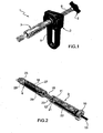
figure 1 shows a perspective view of a mixer used according to the invention with one mixing unit and one dispensing unit operatively connected; -
figure 2 shows a perspective view of a detail of one mixing unit connected to a cartridge used according to the invention containing the liquid phase; -
figure 3 shows a detail of the cartridge offigure 2 ; -
figure 4 shows a detail of the mixing unit offigure 2 ; -
figure 5 shows a detail of the connection between the mixing unit and the dispensing unit offigure 1 ; -
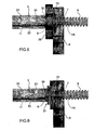
figure 6 shows schematically a lateral snap-in connection between the mixing unit and the dispensing unit; -
figure 7 illustrates a perspective view of the mixing unit in another form of embodiment of the mixer used according to the invention; -
figure 8 represents a perspective view of the stirrer of the mixing unit offigure 7 ; -
figure 9 shows a perspective view of another form of embodiment of the stirrer of the mixing unit offigure 7 ; -
figure 10 illustrates a perspective view of a syringe being used associable with the mixing unit offigure 7 ; -
figure 11 represents a perspective view of the mixing unit offigure 7 coupled to the cartridge containing the liquid phase of the compound; -
figure 12 shows a perspective view of the mixing unit offigure 7 coupled to the syringe being used; -
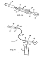
figure 13 illustrates a perspective view of the mixing unit offigure 7 in the phase of compound dispensing inside the syringe being used; -
figure 14 represents a perspective view of the dispensing unit of the mixer used according to the invention, in another form of embodiment; -
figure 15 shows a perspective view of a detail of the dispensing unit offigure 14 , coupled to the mixing unit; -
figure 16 illustrates a perspective view of the dispensing unit of the mixer used according to the invention, in another form of embodiment; -
figure 17 represents a perspective view of the electromechanical actuator of the dispensing unit offigure 16 . - With reference to the drawings, 1 designates a mixer for biphasic compounds used according to the invention in one of its embodiments.
- The
mixer 1 of biphasic compounds used according to the invention comprises one mixing unit, indicated with 3, one dispensing unit, indicated with 2 and one cartridge, indicated with 4, containing the liquid phase and which can be connected together in order to mix the liquid phase with the solid phase and to dispense a quantity of the mixed biphasic compound. - In more detail, and in particular with reference to
figures 2 and3 , themixer 1 comprising achamber 21 for containing asolid phase 22, and acartridge 4 containing aphial 18 of a liquid phase. - The
chamber 21 and thecartridge 4 can communicate through therelative channels external thread 17 made by thechannel 19 of thecartridge 4 and which engages with aninternal thread 16 of alocking ring nut 15 turning around thechannel 20 of themixing chamber 21. - According to the invention, the
cartridge 4 advantageously comprises anexternal casing 25 made in a deformable material so that thephial 18, being the breakable type, once connected to thechamber 21, can be broken from the outside, e.g. on abreaking point 28, according to the method of the type known. - When the phial has been broken the deformable casing can then be squeezed and the liquid transferred inside the
chamber 21 through thechannels chamber 21. Advantageously, with this technical solution, the liquid phase is joined with the solid phase inside thechamber 21 simply, in a completely sterile fashion and with no contact with the outside and without the minimum mechanical or structural complication. - The
casing 25 is made in a flexible material - that is, that acts substantially in an elastic way - and has aninternal volume 29 greater than the volume taken up by saidphial 18. - With this solution it is possible to exploit an advantageous pumping effect to force the liquid into the
chamber 21 without having to provide other or more complicated auxiliary devices. - With particular reference to
figures 4 and5 , themixing unit 3 and thedispensing unit 2 used according to the invention are described in more detail. In the form of embodiment described here, theunit 3 is in the shape of a syringe body comprising acontainer 24 defining inside it themixing chamber 21, and which has on one end thechannel 20 already described that has aring nut 15 for fixing to thecartridge 4. - On the other end, the
container 24 has apiston 23 which seals thechamber 21 and fixing means 10 for fixing to the dispensingunit 2 which, in the form of embodiment illustrated, are composed of anexternal screw 10 which engages frontally with aninternal screw 9 made in oneblock 26 integral with thehandgrip 8 of theunit 2 which is described in more detail further on. - In different forms of embodiment, the mixing
unit 3 and thedispensing unit 2 can in any case be connected by removable means of different kinds either quick coupling or interlocking like, e.g., a bayonet coupling or a similar type. According to the invention, stirring means are arranged inside thechamber 21 which, in the form of embodiment described, comprise astirrer 12 in the shape of a propeller driven by alongitudinal rod 11 that extends at least along thewhole chamber 21, going through ahole 30 of thepiston 23 and which is hermetically sealed. - Preferably, the
rod 11 also comprises agripping knob 13 which extends beyond thechamber 21 and which facilitates thepropeller 12 manoeuvring. - Note that use of the knob is advantageous but is not essential, for example when one wishes to use a connection between the mixing
unit 3 and thedispensing unit 2 of the lateral snap-in type, e.g. composed of a prismatic coupling (e.g. dovetail) achieved by the transversal movement with respect to a longitudinal axis of the mixer (e.g. the axis of thescrew 6 and/or of the chamber 21). - One possible example of a lateral snap-in
connection 31 is schematised infigure 6 . - When using, the
stirrer 12 can be turned and moved longitudinally by means of therod 11 which slides through thepiston 23 until completing the mixing of the solid phase which is inside thechamber 21 with the liquid phase already in thecartridge 4 and until a biphasic compound is obtained, ready for final dispensing. - Advantageously, the dispensing phase is carried out by means of a
dispensing unit 2 that comprises an extrusion screw with anexternal thread 6 that engages with a correspondinginternal thread 7 created inside thehandgrip 8 so as to advance, subsequent to the rotation of the screw, e.g. by using the knob 5. Subsequent to rotation, thescrew 6 moves forward and presses on thepiston 23 forcing it to slide along the mixingchamber 21. - According to the invention, the
screw 6 has a longitudinalinner cavity 14 that houses therod 11 in a sliding manner, so that as the screw and piston advance therod 11 returns and is concealed inside thecavity 14 without interfering with the dispensing action made by theunit 2. - With this solution an effective mixing of the compound has been achieved and, without any delay, to be able to dispense, in a controlled and accurate way, the quantity wanted of the compound, all under conditions of maximum sterility and absence of manipulations or possible contact of the compound with the outside.
- In another form of embodiment of the mixer for biphasic compounds used according to the invention, represented in
figures 7 to 13 , the mixingunit 3 comprises acontainer 24, substantially in the shape of a syringe, defining the mixingchamber 21 and communicating, on one of its ends, with thechannel 20. The screw means, described previously, are also on this same end for the removable connection to thecartridge 4. - Reference is now made to
figure 7 in particular. Where the other end is, thecontainer 24 is associated with apiston 23 which closes (thus sealing) the mixingchamber 21 to which a manually operatedstem 32 is integrally connected, used to dispense the compound, as is more clearly explained below. In particular, thestem 32 has, on its free end, aneyelet 33 for manual thrusting, or alternatively for being connected to thrusting means which are not represented in the figures enclosed: the thrust exerted on theeyelet 33 does, of course, allow the compound to be dispensed through thechannel 20. Thestem 32 is hollow inside and its axial cavity communicates with thehole 30 of thepiston 23. In the axial cavity of thestem 32 therod 11 is engaged in a sliding manner and has thestirrer 12 for mixing the compound on its end. Thestem 32 also has a pair of opposinglongitudinal slots 34 that communicate with its axial cavity and along which a sort ofhandgrip 35 is guided in a sliding manner: the latter comes out from saidslots 34 sideways and allows therod 11 to move inside thechamber 21 to mix the compound. - The
stirrer 12, represented in particular infigure 8 , comprises a propeller, with a substantially cross shape, where the fourblades 36 have an even cross section and smaller compared to that provided in the previous form of embodiment: this solution is even more effective in association with amixing unit 3 like the one described previously and that can even be quite big. In such a situation therefore, the small dimensions of theblades 36 of thestirrer 12 limit resistance to stirring which the operator is aware of and feels especially when the compound being prepared has a relatively high viscosity. - In one of its alternative forms of embodiment, represented in
figure 9 , thestirrer 12 is composed of a propeller comprising six blades for applications in which the compound to be prepared has a relative low viscosity. - In addition, the mixer, according to this current form of embodiment, comprises at least one syringe, indicated with 37 and represented in
figure 10 , usable for dosing the quantity of compound to use in each arthroplasty operation. Thesyringe 37 is, in fact, smaller compared to themixing unit 3 and in particular it substantially corresponds to the dose required for each operation. - The
syringe 37 has aninternal dispensing volume 38 delimited by adispensing piston 39, sliding freely and sealed. On one of its ends thesyringe 37 hasscrew elements 40 for the removable and sealed connection to thering nut 15 of themixing unit 3, e.g. composed of an external thread on this same end; in addition, thescrew elements 40 can comprise, in an equal measure and whenever demanded by application requirements, a sealed fixing ring nut. - The way in which the mixer is used according to this form of embodiment is the following.
- Once the
mixing unit 3 is ready with the solid phase of the compound and thecartridge 4 with the liquid phase of the compound, they are connected together with the screw means 15 as illustrated infigure 11 . After this thephial 18 must be broken and then thecasing 25 squeezed to push the liquid phase inside thechamber 21. When all the liquid phase has been pushed inside thechamber 21, operate thehandgrip 35 of thestirrer 12 manually so thestirrer 12 moves axially and alternatively inside thechamber 21, mixing the two phases and obtaining the compound required. - Now, to achieve the exact dosage of the quantity of compound to use in an arthroplasty operation, separate the
casing 25, emptied of its contents, from the mixingunit 3 and connect thesyringe 37 described previously to themixing unit 3, using thescrew elements 40 as shown infigure 12 . Lastly, operate on theeyelet 33 of themixing unit 3, exerting sufficient manual pressure so as to transfer a certain quantity of the compound from thechamber 21 to the dispensingvolume 38, as can be seen infigure 13 : the quantity of compound transferred will, of course, be defined by the dispensingvolume 38 itself and so will be used effectively in the surgical operation without having to proceed with other dosing operations. - In another form of embodiment of the mixer used according to the invention, represented in
figures 14 and15 , the mixingunit 3 comprises acontainer 24, which is substantially in the shape of a syringe, defining the mixingchamber 21 and in which the compound can be prepared using thecartridge 4 as explained in the previous forms of embodiment. - With particular reference to
figure 14 , the dispensingunit 2 of the compound comprises, in this current form of embodiment, adrive element 41 for thepiston 23 of themixing unit 3 which can be remotely started, as will be made clearer further on. Such remote starting considerably reduces exposure of the operators to any radiation there may be in the area where the surgical operation is being performed. - The
drive element 41, represented in detail infigure 15 associated with themixing unit 3, comprises a syringe element inside which adrive piston 42 slides in a hermetically sealed way, connected to a respective axial drive stem 43: thedrive piston 42 defines, together with the sides of the syringe element, adrive chamber 44. On one of its ends, thedrive element 41 comprises a threadedopening 45 that connects to themixing unit 3 while on the other end it comprises atang 46 with anaxial hole 47 allowing thedrive chamber 44 to communicate with the outside. - The dispensing
unit 2 also comprises pumping means, indicated with 48, of a thrusting fluid for the drive piston 42: these pumping means 48 are suitable for making thedrive stem 43 move in such a way that it presses thepiston 23 of themixing unit 3 and dispenses the compound during the surgical operation. The use of the above mentioned pumping means 48 allows the command and the control of the compound dispensing to be located remotely so that the operators are in an area protected against radiation. - The pumping means 48 comprise a
hand pump 49 composed of acylindrical chamber 50 inside which a manually operatedplunger 51 slides. Thecylindrical chamber 50 has afirst fitting 52 which communicates with atank 53 of fluid and asecond fitting 54 which is coaxial to thecylindrical chamber 50. - The
tank 53 is composed of a disposable bag made in a known type of plastic material, containing a sterile physiological solution; afirst pipe 55 connects thetank 53 to thefirst fitting 52 in a unidirectional way by means of, e.g., a check valve of the known type and not shown in the figures. - A
second pipe 56, of an appropriate length, connects in a unidirectional way by means of, e.g., a check valve of the known type and not shown in the figures - - the
second fitting 54 to athird fitting 57 mounted by thetang 46 of thedrive element 41. - The way in which the mixer is used according to this form of embodiment is the following. Once the compound has been prepared with the
mixing unit 3, according to the procedures described above, the mixingunit 3 is connected, in a sealed way, to the opening 45: in this way the end of thedrive stem 43 is moved into contact with thepiston 23 of themixing unit 3. - Then, by means of the
hand pump 49, theplunger 51 is pulled towards the outside so the physiological solution can go from thetank 53 into thecylindrical chamber 50 through thefirst pipe 55. Subsequently, by exerting pressure on theplunger 51, the physiological solution flows through thesecond pipe 56 so that the solution, having reached an appropriate pressure, makes thedrive piston 42 move with the relative drive stem 43: in this way we have a thrusting action on thepiston 23 of themixing unit 3 which dispenses the compound inside, e.g., a syringe like the one described previously, or other means and/or devices provided for carrying out the operation and which are not the object of this invention. - Yet another form of embodiment of the mixer used according to the invention is represented in
figures 16 ,17 . - In this form of embodiment, the pumping means 48 of the physiological solution, introduced in the previous form of embodiment, comprise a remotely controllable
electromechanical pump 58 which requires no manual work by the operators. More in detail, thiselectromechanical pump 58 comprises acylindrical chamber 50 similar to the one described in the previous form of embodiment, i.e. having a first communicating fitting with afirst pipe 55 and a second communicating fitting 54 with asecond pipe 56. A hermetically sealedplunger 51 slides inside thecylindrical chamber 50, theplunger 51 being associated with anelectromechanical actuator 59, represented in detail infigure 17 and which, in turn, is fixed to thecylindrical chamber 50. Theelectromechanical actuator 59 comprises anelectric motor 60 coupled to a screw mechanism of the type known, that acts on theplunger 51 which slides inside acylindrical guide 61 integral with themotor 60. - The
motor 60 has a terminal 62 for the electrical connection, viacables 63, to a receivingstation 64 of radio control signals emitted by a transmitting station, not represented in the figures but of the type known, and which is remotely operated by the operators. As mentioned previously, thefirst fitting 52 connects thecylindrical chamber 50 to atank 53 of physiological solution, while thesecond fitting 54 hydraulically connects thecylindrical chamber 50 to thethird fitting 57 on thedrive element 40, already described. - This technical solution allows control of the pumping means 48 to be transferred to any position protected against the radiations there could be in the room and, in addition, does not require the manual operation of the above mentioned means 48.
- Another form of embodiment envisages one
dispensing unit 2 of the compound comprising adrive element 41 that can be started remotely, suitable for exerting a thrust of pressure on thepiston 23 of themixing unit 3 so the compound can be dispensed. - More in detail, the dispensing
unit 2 comprises an electromechanical actuator of the type similar to the one illustrated infigure 17 , interlocked to a receiving station like the one shown infigure 16 . Theplunger 51 of theelectromechanical actuator 59 can be connected mechanically to thedrive piston 42 so that, subsequent to a suitable command signal received from a transmitting station, thedrive stem 32 of thedrive element 41 can press on thepiston 23 and thus dispense the compound. - This invention has been described according to preferred forms of embodiment but equivalent variants can be conceived without falling outside the protection scope of these claims.
Claims (13)
- Method for mixing biphasic compounds, comprising a mixer comprising a chamber (21) for containing a solid phase (22) and a cartridge (4) containing a phial (18) of a liquid phase (27), wherein said phial (18) is of the breakable type, said chamber (21) and said cartridge (4) being able to communicate through respective channels (19, 20), wherein said cartridge (4) comprises an external casing (25) made in a deformable and elastic material and has an internal volume (29) greater than the volume taken up by said phial (18), comprising the following steps:break said phial (18) from the outside on a breaking point (28),squeeze the external casing (25) to pump and transfer said liquid phase (27) inside said chamber (21) through said channels (19, 20).
- Method as claimed in claim 1, characterized in that said mixer comprises at least a syringe (37) associable in a removable manner with a mixing unit (3), suitable for dosing the quantity of compound to use, said mixing unit (3) comprising a container (24), which is substantially in the shape of a syringe and defines said chamber (21).
- Method according to claim 2, characterized in that said syringe (37) comprises at least a dispensing piston (39), axially sliding, which defines at least a dispensing volume (38) for dosing the quantity of compound to use, and screw elements (40) for the removable and sealed connection to said mixing unit (3).
- Method according to claim 1, comprising one mixing unit (3) and one dispensing unit (2) operatively connected for mixing said liquid phase (27) and said solid phase (22) through stirring means operating inside said mixing chamber (21), and for dispensing a quantity of mixed biphasic compound through a channel (20) of said chamber (21), said mixing unit (3) comprising a container (24), which is substantially in the shape of a syringe and defines said chamber (21), wherein said stirring means comprise a stirrer (12) driven by a longitudinal rod (11) and wherein said mixer comprises a piston (23) sliding longitudinally on command along said chamber (21) and with a hole (30) to house said rod (11) in a sliding manner.
- Method according to claim 4, characterized in that said dispensing unit (2) comprises an extrusion screw (6) having a longitudinal cavity (14) suitable for housing said rod (11) in a sliding manner and operatively associable with said mixing unit (3) to control the longitudinal movement of the piston (23) along the chamber (21).
- Method according to claim 4 or 5, characterized in that said mixing unit (3) and said dispensing unit (2) are frontally connected through screw means (9, 10).
- Method according to claim 4 or 5, characterized in that said mixing unit (3) and said dispensing unit (2) are connected through front interlocking means, e.g. bayonet coupling means.
- Method according to claim 4 or 5, characterized in that said mixing unit (3) and said dispensing unit (2) are connected through lateral snap-in means.
- Method according to one of the claims 4-8, characterized in that said stirrer (12) is in the shape of a propeller.
- Method according to one of the claims 4-9,
characterized in that said rod (11) comprises a gripping knob (13). - Method according to one of the claims 4-10,
characterized in that said dispensing unit (2) comprises a knob (5) controlling said extrusion screw (6). - Method according to one of the claims 4-11,
characterized in that said dispensing unit (2) comprises a handgrip (8). - Method according to claim 1, characterized in that said chamber (21) and said cartridge (4) can be connected through screw means (16, 17).
Priority Applications (1)
| Application Number | Priority Date | Filing Date | Title |
|---|---|---|---|
| EP14197227.3A EP2881084B1 (en) | 2009-02-06 | 2009-02-06 | Mixer for biphasic compounds and cartridge therefor |
Applications Claiming Priority (1)
| Application Number | Priority Date | Filing Date | Title |
|---|---|---|---|
| PCT/IB2009/000220 WO2010089622A1 (en) | 2009-02-06 | 2009-02-06 | Mixer for biphasic compounds |
Related Child Applications (2)
| Application Number | Title | Priority Date | Filing Date |
|---|---|---|---|
| EP14197227.3A Division-Into EP2881084B1 (en) | 2009-02-06 | 2009-02-06 | Mixer for biphasic compounds and cartridge therefor |
| EP14197227.3A Division EP2881084B1 (en) | 2009-02-06 | 2009-02-06 | Mixer for biphasic compounds and cartridge therefor |
Publications (2)
| Publication Number | Publication Date |
|---|---|
| EP2393456A1 EP2393456A1 (en) | 2011-12-14 |
| EP2393456B1 true EP2393456B1 (en) | 2015-01-21 |
Family
ID=41139060
Family Applications (2)
| Application Number | Title | Priority Date | Filing Date |
|---|---|---|---|
| EP14197227.3A Active EP2881084B1 (en) | 2009-02-06 | 2009-02-06 | Mixer for biphasic compounds and cartridge therefor |
| EP20090785803 Active EP2393456B1 (en) | 2009-02-06 | 2009-02-06 | Mixer and method for mixing biphasic compounds |
Family Applications Before (1)
| Application Number | Title | Priority Date | Filing Date |
|---|---|---|---|
| EP14197227.3A Active EP2881084B1 (en) | 2009-02-06 | 2009-02-06 | Mixer for biphasic compounds and cartridge therefor |
Country Status (6)
| Country | Link |
|---|---|
| US (1) | US9016925B2 (en) |
| EP (2) | EP2881084B1 (en) |
| KR (2) | KR101832498B1 (en) |
| CN (1) | CN102307545B (en) |
| ES (2) | ES2533790T3 (en) |
| WO (1) | WO2010089622A1 (en) |
Cited By (3)
| Publication number | Priority date | Publication date | Assignee | Title |
|---|---|---|---|---|
| EP4385613A1 (en) | 2022-12-13 | 2024-06-19 | Heraeus Medical GmbH | Device for mixing bone cement |
| EP4545027A1 (en) | 2023-10-26 | 2025-04-30 | Heraeus Medical GmbH | Device for extruding bone cement, use and system |
| EP4566701A1 (en) | 2023-12-07 | 2025-06-11 | Heraeus Medical GmbH | Kit for producing and extruding bone cement and method |
Families Citing this family (15)
| Publication number | Priority date | Publication date | Assignee | Title |
|---|---|---|---|---|
| CN106290819B (en) * | 2015-05-27 | 2018-06-19 | 艾博生物医药(杭州)有限公司 | A kind of device for mixing at least two substances |
| KR20200020657A (en) * | 2016-11-02 | 2020-02-26 | 크리스토퍼 제이 피 벨리스 | Devices and Methods for Slurry Generation |
| US11324673B2 (en) | 2016-11-18 | 2022-05-10 | Miraki Innovation Think Tank Llc | Cosmetic appearance of skin |
| MX2019011995A (en) | 2017-04-05 | 2020-01-20 | Miraki Innovation Think Tank Llc | Point of delivery cold slurry generation. |
| AU2018249540A1 (en) | 2017-04-05 | 2019-10-31 | Miraki Innovation Think Tank Llc | Cold slurry containment |
| US10575887B2 (en) | 2017-08-04 | 2020-03-03 | Medtronic Holding Company Sàrl | Dispensing system and methods of use |
| US10981129B2 (en) * | 2017-08-07 | 2021-04-20 | Inventprise, Llc | Double chamber device for point of use mixing |
| US10500342B2 (en) * | 2017-08-21 | 2019-12-10 | Miraki Innovation Think Tank Llc | Cold slurry syringe |
| CN107595626B (en) * | 2017-11-08 | 2020-07-24 | 周方敏 | Medicament inhalation device |
| CN109604284B (en) * | 2018-12-04 | 2021-10-08 | 钱俊 | Hydraulic cylinder inner wall cleaner |
| US11197705B2 (en) * | 2019-07-24 | 2021-12-14 | Shao-Kang Hsueh | Bone cement injection device |
| LT4135830T (en) | 2020-12-23 | 2024-12-10 | Tolmar International Limited | Systems and methods for mixing syringe valve assemblies |
| IT202100024638A1 (en) * | 2021-09-27 | 2023-03-27 | Tecres Spa | Mixing device of at least two compounds |
| USD1029245S1 (en) | 2022-06-22 | 2024-05-28 | Tolmar International Limited | Syringe connector |
| FR3164921A1 (en) * | 2024-07-25 | 2026-01-30 | Histone | Device for mixing and injecting a composition, in particular a bone cement |
Family Cites Families (30)
| Publication number | Priority date | Publication date | Assignee | Title |
|---|---|---|---|---|
| US2908555A (en) * | 1955-07-15 | 1959-10-13 | Drager Otto H | Gas detecting device |
| US2831606A (en) * | 1956-11-16 | 1958-04-22 | Alters Merle Eugene | Method and device for kneading and removing a viscous material from its container |
| US3570486A (en) * | 1968-10-14 | 1971-03-16 | Horizon Ind Ltd | Mixing syringe |
| US3618216A (en) * | 1970-05-12 | 1971-11-09 | Charles G Jaeger | Process and apparatus for mixing and dispensing dental plaster |
| US3724077A (en) * | 1971-11-26 | 1973-04-03 | Unitek Corp | Mixing syringe |
| DE2913283C3 (en) * | 1979-04-03 | 1982-05-27 | Drägerwerk AG, 2400 Lübeck | Detector tubes for measuring chromate and chromic acid aerosols in air |
| DE2948218C2 (en) * | 1979-11-30 | 1982-06-09 | Drägerwerk AG, 2400 Lübeck | Test tube for the quantitative determination of sulfuric acid aerosols |
| US4686192A (en) * | 1983-09-02 | 1987-08-11 | Electric Power Research Institute, Inc. | Method for detecting impurities in an oil sample |
| US4743229A (en) | 1986-09-29 | 1988-05-10 | Collagen Corporation | Collagen/mineral mixing device and method |
| IT1236864B (en) * | 1989-12-29 | 1993-04-22 | Tecres Spa | PROCEDURE FOR MIXING AND ADMINISTRATING A TWO-PART BONE CONCRETE DIRECTLY ON THE SPOT, AND DEVICE THAT REALIZES IT |
| US5297698A (en) * | 1991-07-25 | 1994-03-29 | Minnesota Mining And Manufacturing Company | Two-stage mixing and dispensing assembly for preparations such as dental cements |
| DE19532015A1 (en) * | 1995-08-31 | 1997-03-06 | Alfred Von Schuckmann | Device for mixing and dispensing multi-component products |
| US5876116A (en) * | 1996-11-15 | 1999-03-02 | Barker; Donald | Integrated bone cement mixing and dispensing system |
| US6116773A (en) * | 1999-01-22 | 2000-09-12 | Murray; William M. | Bone cement mixer and method |
| SE521945C2 (en) | 1999-02-26 | 2003-12-23 | Biomet Merck Cementing Technol | Mixing device for making bone cement |
| US6984063B2 (en) * | 2002-10-07 | 2006-01-10 | Advanced Biomaterial Systems, Inc. | Apparatus for mixing and dispensing components |
| DE10152115A1 (en) * | 2001-10-23 | 2003-05-08 | Bosch Gmbh Robert | Device for mixing at least two fluids |
| ITVI20020140A1 (en) | 2002-06-26 | 2003-12-29 | Tecres Spa | DEVICE FOR THE MANUAL DOSING OF A MEDICAL FLUID, PARTICULARLY BONE CEMENT |
| DE10242984B4 (en) * | 2002-09-17 | 2010-09-23 | Sanatis Gmbh | Device for producing mixtures of two components |
| GB2398741B (en) | 2003-02-05 | 2005-04-13 | Summit Medical Ltd | Orthopaedic cement mixing device |
| ITMO20030057A1 (en) * | 2003-03-04 | 2004-09-05 | Sidam Di Azzolini Graziano E C S A S | DEVICE FOR THE PACKAGING, MIXING AND APPLICATION OF BONE CEMENT. |
| BRPI0413681A (en) | 2003-08-21 | 2006-10-24 | Mixpac Systems Ag | device and process for storing, mixing and dispensing components |
| US7524103B2 (en) * | 2003-11-18 | 2009-04-28 | Boston Scientific Scimed, Inc. | Apparatus for mixing and dispensing a multi-component bone cement |
| US20050105384A1 (en) * | 2003-11-18 | 2005-05-19 | Scimed Life Systems, Inc. | Apparatus for mixing and dispensing a multi-component bone cement |
| US7441652B2 (en) * | 2004-05-20 | 2008-10-28 | Med Institute, Inc. | Mixing system |
| US8038682B2 (en) * | 2004-08-17 | 2011-10-18 | Boston Scientific Scimed, Inc. | Apparatus and methods for delivering compounds into vertebrae for vertebroplasty |
| ITVI20050152A1 (en) | 2005-05-20 | 2006-11-21 | Tecres Spa | CARTRIDGE FOR CONSERVATION AND STERILE DISTRIBUTION OF A BIPHASIC COMPOUND, PARTICULARLY FOR AN ACRYLIC RESIN |
| ITVI20050187A1 (en) * | 2005-06-28 | 2006-12-29 | Tecres Spa | CARTRIDGE FOR STERILE MIXING OF A BIPHASIC COMPOUND, PERTICULARLY FOR BICOMPONENT ACRYLIC RESINS |
| EP1984105B1 (en) * | 2006-02-10 | 2010-08-18 | Dow Global Technologies Inc. | Device and method comprising a retractable mixing element |
| EP2066432B1 (en) * | 2006-10-06 | 2015-02-11 | Stryker Corporation | Bone cement mixing and delivery system with automated bone cement transfer between mixer and delivery device |
-
2009
- 2009-02-06 CN CN200980156166.XA patent/CN102307545B/en active Active
- 2009-02-06 EP EP14197227.3A patent/EP2881084B1/en active Active
- 2009-02-06 ES ES09785803.9T patent/ES2533790T3/en active Active
- 2009-02-06 KR KR1020117018280A patent/KR101832498B1/en active Active
- 2009-02-06 ES ES14197227.3T patent/ES2614459T3/en active Active
- 2009-02-06 US US13/148,185 patent/US9016925B2/en active Active
- 2009-02-06 KR KR1020167028250A patent/KR101780914B1/en active Active
- 2009-02-06 WO PCT/IB2009/000220 patent/WO2010089622A1/en not_active Ceased
- 2009-02-06 EP EP20090785803 patent/EP2393456B1/en active Active
Cited By (4)
| Publication number | Priority date | Publication date | Assignee | Title |
|---|---|---|---|---|
| EP4385613A1 (en) | 2022-12-13 | 2024-06-19 | Heraeus Medical GmbH | Device for mixing bone cement |
| EP4545027A1 (en) | 2023-10-26 | 2025-04-30 | Heraeus Medical GmbH | Device for extruding bone cement, use and system |
| US12599423B2 (en) | 2023-10-26 | 2026-04-14 | Heraeus Medical Gmbh | Apparatus for pressing out bone cement, use and system |
| EP4566701A1 (en) | 2023-12-07 | 2025-06-11 | Heraeus Medical GmbH | Kit for producing and extruding bone cement and method |
Also Published As
| Publication number | Publication date |
|---|---|
| ES2533790T3 (en) | 2015-04-14 |
| KR20110111467A (en) | 2011-10-11 |
| EP2393456A1 (en) | 2011-12-14 |
| CN102307545B (en) | 2016-06-15 |
| US20120092951A1 (en) | 2012-04-19 |
| KR101832498B1 (en) | 2018-02-26 |
| ES2614459T3 (en) | 2017-05-31 |
| KR101780914B1 (en) | 2017-10-10 |
| US9016925B2 (en) | 2015-04-28 |
| CN102307545A (en) | 2012-01-04 |
| EP2881084A1 (en) | 2015-06-10 |
| KR20160124235A (en) | 2016-10-26 |
| EP2881084B1 (en) | 2016-11-16 |
| WO2010089622A1 (en) | 2010-08-12 |
Similar Documents
| Publication | Publication Date | Title |
|---|---|---|
| EP2393456B1 (en) | Mixer and method for mixing biphasic compounds | |
| US9643139B2 (en) | Supply unit for a mixer of two-phase compounds | |
| EP2066432B1 (en) | Bone cement mixing and delivery system with automated bone cement transfer between mixer and delivery device | |
| CA2972484C (en) | Bone cement applicator with three-way valve for pressure relief | |
| WO2007139758A2 (en) | Delivery of multicomponent compositions | |
| US20160038209A1 (en) | Method and Assembly for Preparing and Dispensing a Paste | |
| EP3265016B1 (en) | Dental material delivery system |
Legal Events
| Date | Code | Title | Description |
|---|---|---|---|
| PUAI | Public reference made under article 153(3) epc to a published international application that has entered the european phase |
Free format text: ORIGINAL CODE: 0009012 |
|
| 17P | Request for examination filed |
Effective date: 20110906 |
|
| AK | Designated contracting states |
Kind code of ref document: A1 Designated state(s): AT BE BG CH CY CZ DE DK EE ES FI FR GB GR HR HU IE IS IT LI LT LU LV MC MK MT NL NO PL PT RO SE SI SK TR |
|
| DAX | Request for extension of the european patent (deleted) | ||
| 17Q | First examination report despatched |
Effective date: 20120921 |
|
| GRAP | Despatch of communication of intention to grant a patent |
Free format text: ORIGINAL CODE: EPIDOSNIGR1 |
|
| INTG | Intention to grant announced |
Effective date: 20140219 |
|
| GRAS | Grant fee paid |
Free format text: ORIGINAL CODE: EPIDOSNIGR3 |
|
| GRAP | Despatch of communication of intention to grant a patent |
Free format text: ORIGINAL CODE: EPIDOSNIGR1 |
|
| INTG | Intention to grant announced |
Effective date: 20140731 |
|
| GRAA | (expected) grant |
Free format text: ORIGINAL CODE: 0009210 |
|
| AK | Designated contracting states |
Kind code of ref document: B1 Designated state(s): AT BE BG CH CY CZ DE DK EE ES FI FR GB GR HR HU IE IS IT LI LT LU LV MC MK MT NL NO PL PT RO SE SI SK TR |
|
| REG | Reference to a national code |
Ref country code: GB Ref legal event code: FG4D |
|
| REG | Reference to a national code |
Ref country code: CH Ref legal event code: EP |
|
| REG | Reference to a national code |
Ref country code: IE Ref legal event code: FG4D |
|
| REG | Reference to a national code |
Ref country code: DE Ref legal event code: R096 Ref document number: 602009029125 Country of ref document: DE Effective date: 20150305 |
|
| REG | Reference to a national code |
Ref country code: AT Ref legal event code: REF Ref document number: 708808 Country of ref document: AT Kind code of ref document: T Effective date: 20150315 |
|
| REG | Reference to a national code |
Ref country code: ES Ref legal event code: FG2A Ref document number: 2533790 Country of ref document: ES Kind code of ref document: T3 Effective date: 20150414 |
|
| REG | Reference to a national code |
Ref country code: NL Ref legal event code: VDEP Effective date: 20150121 |
|
| REG | Reference to a national code |
Ref country code: AT Ref legal event code: MK05 Ref document number: 708808 Country of ref document: AT Kind code of ref document: T Effective date: 20150121 |
|
| REG | Reference to a national code |
Ref country code: LT Ref legal event code: MG4D |
|
| PG25 | Lapsed in a contracting state [announced via postgrant information from national office to epo] |
Ref country code: BE Free format text: LAPSE BECAUSE OF NON-PAYMENT OF DUE FEES Effective date: 20150228 |
|
| PG25 | Lapsed in a contracting state [announced via postgrant information from national office to epo] |
Ref country code: LT Free format text: LAPSE BECAUSE OF FAILURE TO SUBMIT A TRANSLATION OF THE DESCRIPTION OR TO PAY THE FEE WITHIN THE PRESCRIBED TIME-LIMIT Effective date: 20150121 Ref country code: NO Free format text: LAPSE BECAUSE OF FAILURE TO SUBMIT A TRANSLATION OF THE DESCRIPTION OR TO PAY THE FEE WITHIN THE PRESCRIBED TIME-LIMIT Effective date: 20150421 Ref country code: FI Free format text: LAPSE BECAUSE OF FAILURE TO SUBMIT A TRANSLATION OF THE DESCRIPTION OR TO PAY THE FEE WITHIN THE PRESCRIBED TIME-LIMIT Effective date: 20150121 Ref country code: BG Free format text: LAPSE BECAUSE OF FAILURE TO SUBMIT A TRANSLATION OF THE DESCRIPTION OR TO PAY THE FEE WITHIN THE PRESCRIBED TIME-LIMIT Effective date: 20150421 Ref country code: SE Free format text: LAPSE BECAUSE OF FAILURE TO SUBMIT A TRANSLATION OF THE DESCRIPTION OR TO PAY THE FEE WITHIN THE PRESCRIBED TIME-LIMIT Effective date: 20150121 Ref country code: HR Free format text: LAPSE BECAUSE OF FAILURE TO SUBMIT A TRANSLATION OF THE DESCRIPTION OR TO PAY THE FEE WITHIN THE PRESCRIBED TIME-LIMIT Effective date: 20150121 |
|
| PG25 | Lapsed in a contracting state [announced via postgrant information from national office to epo] |
Ref country code: PL Free format text: LAPSE BECAUSE OF FAILURE TO SUBMIT A TRANSLATION OF THE DESCRIPTION OR TO PAY THE FEE WITHIN THE PRESCRIBED TIME-LIMIT Effective date: 20150121 Ref country code: IS Free format text: LAPSE BECAUSE OF FAILURE TO SUBMIT A TRANSLATION OF THE DESCRIPTION OR TO PAY THE FEE WITHIN THE PRESCRIBED TIME-LIMIT Effective date: 20150521 Ref country code: GR Free format text: LAPSE BECAUSE OF FAILURE TO SUBMIT A TRANSLATION OF THE DESCRIPTION OR TO PAY THE FEE WITHIN THE PRESCRIBED TIME-LIMIT Effective date: 20150422 Ref country code: NL Free format text: LAPSE BECAUSE OF FAILURE TO SUBMIT A TRANSLATION OF THE DESCRIPTION OR TO PAY THE FEE WITHIN THE PRESCRIBED TIME-LIMIT Effective date: 20150121 Ref country code: LV Free format text: LAPSE BECAUSE OF FAILURE TO SUBMIT A TRANSLATION OF THE DESCRIPTION OR TO PAY THE FEE WITHIN THE PRESCRIBED TIME-LIMIT Effective date: 20150121 Ref country code: AT Free format text: LAPSE BECAUSE OF FAILURE TO SUBMIT A TRANSLATION OF THE DESCRIPTION OR TO PAY THE FEE WITHIN THE PRESCRIBED TIME-LIMIT Effective date: 20150121 |
|
| REG | Reference to a national code |
Ref country code: CH Ref legal event code: PL |
|
| REG | Reference to a national code |
Ref country code: DE Ref legal event code: R097 Ref document number: 602009029125 Country of ref document: DE |
|
| PG25 | Lapsed in a contracting state [announced via postgrant information from national office to epo] |
Ref country code: CZ Free format text: LAPSE BECAUSE OF FAILURE TO SUBMIT A TRANSLATION OF THE DESCRIPTION OR TO PAY THE FEE WITHIN THE PRESCRIBED TIME-LIMIT Effective date: 20150121 Ref country code: LI Free format text: LAPSE BECAUSE OF NON-PAYMENT OF DUE FEES Effective date: 20150228 Ref country code: SK Free format text: LAPSE BECAUSE OF FAILURE TO SUBMIT A TRANSLATION OF THE DESCRIPTION OR TO PAY THE FEE WITHIN THE PRESCRIBED TIME-LIMIT Effective date: 20150121 Ref country code: DK Free format text: LAPSE BECAUSE OF FAILURE TO SUBMIT A TRANSLATION OF THE DESCRIPTION OR TO PAY THE FEE WITHIN THE PRESCRIBED TIME-LIMIT Effective date: 20150121 Ref country code: MC Free format text: LAPSE BECAUSE OF FAILURE TO SUBMIT A TRANSLATION OF THE DESCRIPTION OR TO PAY THE FEE WITHIN THE PRESCRIBED TIME-LIMIT Effective date: 20150121 Ref country code: EE Free format text: LAPSE BECAUSE OF FAILURE TO SUBMIT A TRANSLATION OF THE DESCRIPTION OR TO PAY THE FEE WITHIN THE PRESCRIBED TIME-LIMIT Effective date: 20150121 Ref country code: CH Free format text: LAPSE BECAUSE OF NON-PAYMENT OF DUE FEES Effective date: 20150228 Ref country code: RO Free format text: LAPSE BECAUSE OF FAILURE TO SUBMIT A TRANSLATION OF THE DESCRIPTION OR TO PAY THE FEE WITHIN THE PRESCRIBED TIME-LIMIT Effective date: 20150121 |
|
| REG | Reference to a national code |
Ref country code: IE Ref legal event code: MM4A |
|
| PLBE | No opposition filed within time limit |
Free format text: ORIGINAL CODE: 0009261 |
|
| STAA | Information on the status of an ep patent application or granted ep patent |
Free format text: STATUS: NO OPPOSITION FILED WITHIN TIME LIMIT |
|
| REG | Reference to a national code |
Ref country code: HU Ref legal event code: AG4A Ref document number: E024396 Country of ref document: HU |
|
| 26N | No opposition filed |
Effective date: 20151022 |
|
| REG | Reference to a national code |
Ref country code: FR Ref legal event code: PLFP Year of fee payment: 8 |
|
| PG25 | Lapsed in a contracting state [announced via postgrant information from national office to epo] |
Ref country code: IE Free format text: LAPSE BECAUSE OF NON-PAYMENT OF DUE FEES Effective date: 20150206 |
|
| PG25 | Lapsed in a contracting state [announced via postgrant information from national office to epo] |
Ref country code: SI Free format text: LAPSE BECAUSE OF FAILURE TO SUBMIT A TRANSLATION OF THE DESCRIPTION OR TO PAY THE FEE WITHIN THE PRESCRIBED TIME-LIMIT Effective date: 20150121 |
|
| PG25 | Lapsed in a contracting state [announced via postgrant information from national office to epo] |
Ref country code: BE Free format text: LAPSE BECAUSE OF FAILURE TO SUBMIT A TRANSLATION OF THE DESCRIPTION OR TO PAY THE FEE WITHIN THE PRESCRIBED TIME-LIMIT Effective date: 20150121 |
|
| PG25 | Lapsed in a contracting state [announced via postgrant information from national office to epo] |
Ref country code: MT Free format text: LAPSE BECAUSE OF FAILURE TO SUBMIT A TRANSLATION OF THE DESCRIPTION OR TO PAY THE FEE WITHIN THE PRESCRIBED TIME-LIMIT Effective date: 20150121 |
|
| REG | Reference to a national code |
Ref country code: FR Ref legal event code: PLFP Year of fee payment: 9 |
|
| PG25 | Lapsed in a contracting state [announced via postgrant information from national office to epo] |
Ref country code: CY Free format text: LAPSE BECAUSE OF FAILURE TO SUBMIT A TRANSLATION OF THE DESCRIPTION OR TO PAY THE FEE WITHIN THE PRESCRIBED TIME-LIMIT Effective date: 20150121 |
|
| PG25 | Lapsed in a contracting state [announced via postgrant information from national office to epo] |
Ref country code: PT Free format text: LAPSE BECAUSE OF FAILURE TO SUBMIT A TRANSLATION OF THE DESCRIPTION OR TO PAY THE FEE WITHIN THE PRESCRIBED TIME-LIMIT Effective date: 20150521 |
|
| PG25 | Lapsed in a contracting state [announced via postgrant information from national office to epo] |
Ref country code: TR Free format text: LAPSE BECAUSE OF FAILURE TO SUBMIT A TRANSLATION OF THE DESCRIPTION OR TO PAY THE FEE WITHIN THE PRESCRIBED TIME-LIMIT Effective date: 20150121 |
|
| PG25 | Lapsed in a contracting state [announced via postgrant information from national office to epo] |
Ref country code: LU Free format text: LAPSE BECAUSE OF NON-PAYMENT OF DUE FEES Effective date: 20150206 |
|
| REG | Reference to a national code |
Ref country code: FR Ref legal event code: PLFP Year of fee payment: 10 |
|
| PG25 | Lapsed in a contracting state [announced via postgrant information from national office to epo] |
Ref country code: MK Free format text: LAPSE BECAUSE OF FAILURE TO SUBMIT A TRANSLATION OF THE DESCRIPTION OR TO PAY THE FEE WITHIN THE PRESCRIBED TIME-LIMIT Effective date: 20150121 |
|
| PGFP | Annual fee paid to national office [announced via postgrant information from national office to epo] |
Ref country code: HU Payment date: 20190215 Year of fee payment: 11 |
|
| PG25 | Lapsed in a contracting state [announced via postgrant information from national office to epo] |
Ref country code: HU Free format text: LAPSE BECAUSE OF NON-PAYMENT OF DUE FEES Effective date: 20200207 |
|
| P01 | Opt-out of the competence of the unified patent court (upc) registered |
Effective date: 20230509 |
|
| PGFP | Annual fee paid to national office [announced via postgrant information from national office to epo] |
Ref country code: GB Payment date: 20260121 Year of fee payment: 18 |
|
| PGFP | Annual fee paid to national office [announced via postgrant information from national office to epo] |
Ref country code: ES Payment date: 20260302 Year of fee payment: 18 |
|
| PGFP | Annual fee paid to national office [announced via postgrant information from national office to epo] |
Ref country code: DE Payment date: 20260121 Year of fee payment: 18 |
|
| PGFP | Annual fee paid to national office [announced via postgrant information from national office to epo] |
Ref country code: IT Payment date: 20260121 Year of fee payment: 18 |
|
| PGFP | Annual fee paid to national office [announced via postgrant information from national office to epo] |
Ref country code: FR Payment date: 20260121 Year of fee payment: 18 |