EP2395195A2 - Porte additionelle, notamment porte moustiquaire, avec un mécanisme de fermeture automatique - Google Patents
Porte additionelle, notamment porte moustiquaire, avec un mécanisme de fermeture automatique Download PDFInfo
- Publication number
- EP2395195A2 EP2395195A2 EP11166424A EP11166424A EP2395195A2 EP 2395195 A2 EP2395195 A2 EP 2395195A2 EP 11166424 A EP11166424 A EP 11166424A EP 11166424 A EP11166424 A EP 11166424A EP 2395195 A2 EP2395195 A2 EP 2395195A2
- Authority
- EP
- European Patent Office
- Prior art keywords
- sliding
- frame
- spring
- traction means
- door according
- Prior art date
- Legal status (The legal status is an assumption and is not a legal conclusion. Google has not performed a legal analysis and makes no representation as to the accuracy of the status listed.)
- Granted
Links
- 241000238631 Hexapoda Species 0.000 claims abstract description 6
- 238000013016 damping Methods 0.000 claims description 14
- 238000004804 winding Methods 0.000 description 13
- 229910052782 aluminium Inorganic materials 0.000 description 4
- XAGFODPZIPBFFR-UHFFFAOYSA-N aluminium Chemical compound [Al] XAGFODPZIPBFFR-UHFFFAOYSA-N 0.000 description 4
- 229910000639 Spring steel Inorganic materials 0.000 description 2
- 230000000295 complement effect Effects 0.000 description 2
- 239000004744 fabric Substances 0.000 description 2
- 229910052751 metal Inorganic materials 0.000 description 2
- 239000002184 metal Substances 0.000 description 2
- 230000005540 biological transmission Effects 0.000 description 1
- 239000002131 composite material Substances 0.000 description 1
- 230000003247 decreasing effect Effects 0.000 description 1
- 230000000994 depressogenic effect Effects 0.000 description 1
- 238000009434 installation Methods 0.000 description 1
- 230000002093 peripheral effect Effects 0.000 description 1
- 238000005096 rolling process Methods 0.000 description 1
Images


Classifications
-
- E—FIXED CONSTRUCTIONS
- E06—DOORS, WINDOWS, SHUTTERS, OR ROLLER BLINDS IN GENERAL; LADDERS
- E06B—FIXED OR MOVABLE CLOSURES FOR OPENINGS IN BUILDINGS, VEHICLES, FENCES OR LIKE ENCLOSURES IN GENERAL, e.g. DOORS, WINDOWS, BLINDS, GATES
- E06B9/00—Screening or protective devices for wall or similar openings, with or without operating or securing mechanisms; Closures of similar construction
- E06B9/52—Devices affording protection against insects, e.g. fly screens; Mesh windows for other purposes
-
- E—FIXED CONSTRUCTIONS
- E05—LOCKS; KEYS; WINDOW OR DOOR FITTINGS; SAFES
- E05F—DEVICES FOR MOVING WINGS INTO OPEN OR CLOSED POSITION; CHECKS FOR WINGS; WING FITTINGS NOT OTHERWISE PROVIDED FOR, CONCERNED WITH THE FUNCTIONING OF THE WING
- E05F1/00—Closers or openers for wings, not otherwise provided for in this subclass
- E05F1/08—Closers or openers for wings, not otherwise provided for in this subclass spring-actuated, e.g. for horizontally sliding wings
- E05F1/16—Closers or openers for wings, not otherwise provided for in this subclass spring-actuated, e.g. for horizontally sliding wings for sliding wings
-
- E—FIXED CONSTRUCTIONS
- E05—LOCKS; KEYS; WINDOW OR DOOR FITTINGS; SAFES
- E05F—DEVICES FOR MOVING WINGS INTO OPEN OR CLOSED POSITION; CHECKS FOR WINGS; WING FITTINGS NOT OTHERWISE PROVIDED FOR, CONCERNED WITH THE FUNCTIONING OF THE WING
- E05F5/00—Braking devices, e.g. checks; Stops; Buffers
- E05F5/003—Braking devices, e.g. checks; Stops; Buffers for sliding wings
-
- E—FIXED CONSTRUCTIONS
- E05—LOCKS; KEYS; WINDOW OR DOOR FITTINGS; SAFES
- E05Y—INDEXING SCHEME ASSOCIATED WITH SUBCLASSES E05D AND E05F, RELATING TO CONSTRUCTION ELEMENTS, ELECTRIC CONTROL, POWER SUPPLY, POWER SIGNAL OR TRANSMISSION, USER INTERFACES, MOUNTING OR COUPLING, DETAILS, ACCESSORIES, AUXILIARY OPERATIONS NOT OTHERWISE PROVIDED FOR, APPLICATION THEREOF
- E05Y2201/00—Constructional elements; Accessories therefor
- E05Y2201/20—Brakes; Disengaging means; Holders; Stops; Valves; Accessories therefor
- E05Y2201/21—Brakes
- E05Y2201/212—Buffers
-
- E—FIXED CONSTRUCTIONS
- E05—LOCKS; KEYS; WINDOW OR DOOR FITTINGS; SAFES
- E05Y—INDEXING SCHEME ASSOCIATED WITH SUBCLASSES E05D AND E05F, RELATING TO CONSTRUCTION ELEMENTS, ELECTRIC CONTROL, POWER SUPPLY, POWER SIGNAL OR TRANSMISSION, USER INTERFACES, MOUNTING OR COUPLING, DETAILS, ACCESSORIES, AUXILIARY OPERATIONS NOT OTHERWISE PROVIDED FOR, APPLICATION THEREOF
- E05Y2201/00—Constructional elements; Accessories therefor
- E05Y2201/20—Brakes; Disengaging means; Holders; Stops; Valves; Accessories therefor
- E05Y2201/262—Type of motion, e.g. braking
- E05Y2201/264—Type of motion, e.g. braking linear
-
- E—FIXED CONSTRUCTIONS
- E05—LOCKS; KEYS; WINDOW OR DOOR FITTINGS; SAFES
- E05Y—INDEXING SCHEME ASSOCIATED WITH SUBCLASSES E05D AND E05F, RELATING TO CONSTRUCTION ELEMENTS, ELECTRIC CONTROL, POWER SUPPLY, POWER SIGNAL OR TRANSMISSION, USER INTERFACES, MOUNTING OR COUPLING, DETAILS, ACCESSORIES, AUXILIARY OPERATIONS NOT OTHERWISE PROVIDED FOR, APPLICATION THEREOF
- E05Y2201/00—Constructional elements; Accessories therefor
- E05Y2201/40—Motors; Magnets; Springs; Weights; Accessories therefor
- E05Y2201/404—Function thereof
- E05Y2201/41—Function thereof for closing
-
- E—FIXED CONSTRUCTIONS
- E05—LOCKS; KEYS; WINDOW OR DOOR FITTINGS; SAFES
- E05Y—INDEXING SCHEME ASSOCIATED WITH SUBCLASSES E05D AND E05F, RELATING TO CONSTRUCTION ELEMENTS, ELECTRIC CONTROL, POWER SUPPLY, POWER SIGNAL OR TRANSMISSION, USER INTERFACES, MOUNTING OR COUPLING, DETAILS, ACCESSORIES, AUXILIARY OPERATIONS NOT OTHERWISE PROVIDED FOR, APPLICATION THEREOF
- E05Y2201/00—Constructional elements; Accessories therefor
- E05Y2201/40—Motors; Magnets; Springs; Weights; Accessories therefor
- E05Y2201/47—Springs
- E05Y2201/482—Ribbon springs
-
- E—FIXED CONSTRUCTIONS
- E05—LOCKS; KEYS; WINDOW OR DOOR FITTINGS; SAFES
- E05Y—INDEXING SCHEME ASSOCIATED WITH SUBCLASSES E05D AND E05F, RELATING TO CONSTRUCTION ELEMENTS, ELECTRIC CONTROL, POWER SUPPLY, POWER SIGNAL OR TRANSMISSION, USER INTERFACES, MOUNTING OR COUPLING, DETAILS, ACCESSORIES, AUXILIARY OPERATIONS NOT OTHERWISE PROVIDED FOR, APPLICATION THEREOF
- E05Y2900/00—Application of doors, windows, wings or fittings thereof
- E05Y2900/10—Application of doors, windows, wings or fittings thereof for buildings or parts thereof
- E05Y2900/13—Type of wing
- E05Y2900/132—Doors
- E05Y2900/136—Screens; Insect doors
Definitions
- the invention relates to a front door, in particular an insect screen, comprising a frame and a slidably received in this sliding wing.
- Such prefabricated doors are usually mounted in the balcony or terrace area. It comprises a fixed position, usually encircling frame, which consists mostly of four composite to the frame rectangular shape, metal profile bars, usually aluminum profiles.
- a sliding wing is included, comprising a sash, which is composed of four metal profile bars, usually also aluminum profiles, in which sash a grid or fabric is held by a piping.
- About a roller or sliding bearing of the sliding frame is horizontally displaceable on the positionally fixed frame added. It may, for example, be guided on the upper side over rollers, below a swiveling out of the frame avoiding storage can be provided, is also conceivable on both sides of a roller or sliding guide and the like.
- the user can open the front door by simply sliding the sliding sash to the side. To close it, the sash must be actively pushed back by the user. Occasionally, however, the pushing back is forgotten, or the sliding sash is not pushed back completely into the closed position, so that the auxiliary door remains completely or partially open. This allows ingress of dirt and insects, which should be avoided via the front door actually.
- the invention is thus based on the problem of providing a contrast improved front door, in particular insect screen.
- the sliding sash is connected via a traction means with a retraction element, which builds a restoring force when sliding the sliding sash from the closed position.
- the sliding leaf is automatically brought into the closed position with particular advantage.
- the sliding leaf is connected via a traction means with a retraction element. If the sliding sash, starting from the closed position, in which it rests tightly against a vertical wing of the outer frame, pushed open, so the door is opened, then the retraction element is actuated by moving the sliding sash also moving traction element, it builds with the beginning of postponing a Restoring force, which acts on the traction means and on this on the sliding sash. If the sliding leaf is then released, the restoring force causes the sliding leaf to be automatically withdrawn back into the closed position, ie. h. That relaxes the retraction element and the restoring force is reduced again, associated with a retraction of the sliding leaf in the closed position.
- the retraction element itself is preferably a spring, with the use here of a coil spring or a helical tension spring or a spiral spring, for example in the form of a wound long spring band made of spring steel, offers. Because a coil spring and in particular a coil spring can be considerably deformed to build up the restoring force, the frame and the traction means can be moved over a large horizontal sliding length without the coil spring or the coil spring reaches its limit.
- the traction means may be a band, a string or a chain.
- the traction means is flexible, since it must be accommodated in a Werenburgnecken amid, a suction cup, or a chain.
- the traction means is flexible, since it must be accommodated in a Werenburgnecken amid, a suction cup, or a chain.
- the traction means is flexible, since it must be accommodated in a Werenburgnecken amid, primarily wound when the sliding leaf in the Closed position is from which Switzerlandstofffiten amidos, etc.
- the retraction element in particular the spring, as well as the traction means in a housing which is laterally fixed or attachable to the fixed frame, arranged, from which the traction means is guided to the sliding leaf.
- the retraction element is a helical spring
- the traction means can be fixed, for example, with its one end to a winding ring to which the outer end of the spiral spring located inside the ring is fastened, and then several times around the spiral spring to the winding ring spirally wound, with its other end it is guided to the attachment point on the sliding sash.
- the traction means is unwound from its spiral winding.
- the coil spring is rotated and, as firmly in position with its inner end, further up or unwound and thus curious about what the restoring force is built. If the sliding frame is relieved, then the coil spring relaxes again, it rotates back (depending on the design, the spring expands or it contracts again), wherein the traction device is wound up again and the sliding sash is pulled into the closed position.
- the retraction element, so the spring, and the flexible traction means is in a housing which can be arranged at an arbitrary position laterally on the frame.
- “Sideways” means in direct lateral extension of the frame, but it is also conceivable, depending on the space available to position the housing below the frame or at an angle to the frame standing in the soffit. The mounting position ultimately depends on the structural conditions.
- one or more deflecting rollers which may be variable in their position, are expediently provided in the housing, over which the traction means is guided.
- These pulleys ensure a safe and defect-free traction mechanism.
- the deflecting rollers changeable in their position in the housing, for which they can be positioned for example at corresponding plug positions, which are provided at different locations, so that the pulleys plugged into different places can be.
- the traction means is either on the sliding sash itself or arranged on a sliding wing bearing component, such as a roll holder for roller-guided storage of sliding sash attached, the attachment is preferably releasable to the assembly or disassembly of the traction means from the sash to solve. It offers itself for this purpose a screw or snap fastener.
- the housing in which the traction means is located preferably laterally, the frame extending, attached to the frame.
- the housing is located in the region of the upper or lower end of the positionally fixed frame, ie adjacent to the horizontal upper or lower frame member of the frame.
- the traction means can be easily guided into the frame interior and in the horizontal frame member having a chamber open to the frame inside, for example, engage the rollers of the sliding frame. It is now readily possible to guide the traction means quasi hidden in this horizontal frame member to the sash.
- the restoring force and thus the force with which the sliding leaf is retracted and consequently set and limited the movement speed of the sliding leaf during the return movement.
- damping damping element is provided in the invention. This damping element slows down the movement of the sliding leaf at least when entering the closed position, so that the sliding leaf gently and relatively quietly applies to the frame.
- the damping element is, for example, an elastically deformable element arranged on the frame or on the sliding leaf, in particular a spring element which is compressed into the closed position upon entry of the sliding leaf.
- a spring element may for example be a stop pin or a stop sleeve, which is arranged on a coil spring.
- this spring element is arranged on the vertical frame component of the frame, the tip of this spring element protrudes inwards from the frame surface. Now runs the sliding leaf against this spring element, ie against the sleeve or the pin, the integrated spring is combined, it comes to a damping of the closing movement.
- a spring element comprising a spring may serve as an elastically deformable element but for example, a rubber pin which protrudes from the end face of the vertical frame member and is pressed in the system of the sliding frame inwardly serve.
- the damping element can also be a brush arranged on the frame or on the sliding leaf, for example a brush Brush bar, which extends over the entire vertical length of the frame member or sliding wing member, and the bristles are compressed when entering the closed position. Even with such a brush, the inlet movement can be damped in the closed position.
- a brush Brush bar which extends over the entire vertical length of the frame member or sliding wing member, and the bristles are compressed when entering the closed position. Even with such a brush, the inlet movement can be damped in the closed position.
- the brush for example, on the upper and / or lower horizontal frame member or sliding wing component, such that there is a friction during the movement of the sliding leaf whose Movement is dampened by this brush friction.
- a brush strip is attached to the sliding leaf so that it rests with its bristles against the upper or lower horizontal frame member. The bristles thus grind on a sliding leaf movement on the fixed frame, over which the movement is damped.
- Fig. 1 shows a partial view of a front door according to the invention 1, comprising a positionally fixed, to be arranged in the region of a door reveal frame 2 consisting of four complementary to each other to the rectangular frame members 3, usually extruded aluminum.
- a sliding wing 4 is slidably guided, also comprising a sash 5 consisting of four complementary to each other to the rectangular shape frame profile parts 6, also usually made of extruded aluminum.
- a grid or fabric 7 which is fixed via a piping in a known manner.
- the sliding frame 4 is guided via bearing means 8, in the example shown roller bearings 9, horizontally displaceable in the frame 2.
- bearing means 8 are arranged on the lower horizontally extending frame member 6, run their respective role on a running edge of the horizontal frame member 3 of the fixed-position frame 2.
- corresponding bearing means 8 may also be provided on the upper sliding wing end, or only a simple sliding guide, etc. In each case, a horizontally displaceable movable mounting of the sliding leaf 4 is realized.
- a housing 10 is arranged laterally, in which a retraction element 11 is arranged here in the form of a spiral spring 12 consisting of a spirally wound spring steel strip.
- This coil spring 12 is arranged with its inner end 13 in a fixed position on a holder of the housing 10.
- a drawstring 16 attached, which in turn is wound spirally, such as Fig. 1 shows.
- the second end 17 of the tension band 16 is guided out of the housing 10, it passes through a housing aperture 18 and an opening 19 provided adjacent thereto on the frame 2 and is guided in a hollow chamber 20 of the horizontal frame member 3 of the frame 2.
- the end 17 is detachable via at least one fastening screw 21 with a roller holder 22 of the rolling element 9, but firmly connected.
- the tension band 16 is guided via suitable deflection rollers 23.
- a damping element 24 is provided on the sliding frame 4.
- the damping element 24 is here a spring element, comprising a protruding from the front edge of the vertical frame member 6 of the frame 5 stop pin or stop sleeve 25 which is received in an outer, arranged in the frame interior of the frame 5 guide sleeve 26 and against a spring 27 inward, ie in the frame member 6, can be pressed.
- the spring 27 is compressed, thus urging the stop pin or the stop sleeve 25 always in the outer position, such as Fig. 1 shows. This movement is also represented by the double arrow C.
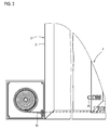
- FIG. 2 This closed position shows Fig. 2 ,
- the sliding leaf 4 is in complete, tight contact with the frame 2, ie, that the left frame member 6 of the sliding frame 5 shown in the embodiment rests with its outer edge 29 on the inner edge 28 of the likewise left frame member 3 of the frame 2.
- the winding of the drawstring 16 has a slightly larger circumference after the drawstring 16 is maximally wound.
- the coil spring 12 is largely relaxed, a certain bias may be given to hold the sliding sash 4 firmly in the closed position.
- the damping element 24 is in the depressed position.
- the housing 10 comprises a first housing component 30 with a side wall 31 and peripheral edge 32. On the side wall 31, a central pin 33 is provided with a holding slot 34, in which the angled end of the thirteenth the coil spring 12 (see Fig. 4C ) is used.
- Fig. 4B shows a first winding plate 35 with an opening 36. This winding plate 35 is initially placed over the pin 34.
- a projecting annular collar 37 is provided, whose diameter is slightly larger than the diameter of the coil spring 12 after Fig. 4C , On an inwardly projecting retaining pin 38, the other end 14 of the coil spring is attached.
- FIG. 4D shown second winding plate 39 set.
- the winding plates 35, 39 thus form two side cheeks, between which the tension band 16 is wound.
- the housing via the lid 40 see Fig. 4F ) closed.
- the figures show a lateral arrangement of the housing 10 on the frame 2, but this can also be arranged at an angle to the frame 2, d. h., it is slightly tilted about the vertical axis.
- pulleys are provided in the housing over which the tension band is deflected accordingly. It is also conceivable to move the exit slot 18 on the housing then on the side.
- Fig. 5 shows an embodiment of a front door according to the invention 1, which in terms of structure, that is, frame 2, sliding panel 4 and housing 10 together with coil spring 12 and tension band 16, etc., corresponds to the embodiment described above.
- another damping element 34 is provided here.
- This is realized here in the form of a brush 41.
- a brush strip 42 is inserted into a corresponding receptacle on the vertical frame member 6 of the sash 5.
- the brush 41 or its bristles protrude from the frame end face. When automatically pulled into the closed position, the brush 41 comes first in contact with the opposite surface 28 of the vertical frame member 3 of the frame 2, wherein the bristles are slightly deformed and attenuate the striking respectively entering the closed position.
Landscapes
- Engineering & Computer Science (AREA)
- Structural Engineering (AREA)
- Life Sciences & Earth Sciences (AREA)
- Insects & Arthropods (AREA)
- Pest Control & Pesticides (AREA)
- Architecture (AREA)
- Civil Engineering (AREA)
- Closing And Opening Devices For Wings, And Checks For Wings (AREA)
- Wing Frames And Configurations (AREA)
- Specific Sealing Or Ventilating Devices For Doors And Windows (AREA)
Applications Claiming Priority (1)
| Application Number | Priority Date | Filing Date | Title |
|---|---|---|---|
| DE201010023444 DE102010023444B4 (de) | 2010-06-11 | 2010-06-11 | Vorsatztür, insbesondere Insektenschutztür |
Publications (3)
| Publication Number | Publication Date |
|---|---|
| EP2395195A2 true EP2395195A2 (fr) | 2011-12-14 |
| EP2395195A3 EP2395195A3 (fr) | 2012-08-15 |
| EP2395195B1 EP2395195B1 (fr) | 2015-01-14 |
Family
ID=44583613
Family Applications (1)
| Application Number | Title | Priority Date | Filing Date |
|---|---|---|---|
| EP11166424.9A Not-in-force EP2395195B1 (fr) | 2010-06-11 | 2011-05-17 | Porte additionelle, notamment porte moustiquaire, avec un mécanisme de fermeture automatique |
Country Status (2)
| Country | Link |
|---|---|
| EP (1) | EP2395195B1 (fr) |
| DE (1) | DE102010023444B4 (fr) |
Cited By (4)
| Publication number | Priority date | Publication date | Assignee | Title |
|---|---|---|---|---|
| AT13523U1 (de) * | 2012-02-28 | 2014-02-15 | Ceta Elektromechanik Gmbh | Verfahrbare Einrichtung mit einem Mittel zum Speichern potenzieller Energie |
| EP2915942A1 (fr) * | 2014-03-07 | 2015-09-09 | Carl Stahl Kromer GmbH | Partie coulissante doté de ressort |
| CN106593944A (zh) * | 2016-12-31 | 2017-04-26 | 毛永波 | 一种伸缩隐形扇叶风轮与风扇 |
| US20250237101A1 (en) * | 2021-12-02 | 2025-07-24 | Elvo Ltd | Adjustable retraction mechanism |
Families Citing this family (4)
| Publication number | Priority date | Publication date | Assignee | Title |
|---|---|---|---|---|
| JP6893798B2 (ja) * | 2017-02-24 | 2021-06-23 | スターテング工業株式会社 | 引戸用クローザ装置 |
| DE102018100188A1 (de) * | 2018-01-05 | 2019-07-11 | Kmw Kühlmöbelwerk Limburg Gmbh | Schließvorrichtung zum selbsttätigen Schließen eines Schiebeelementes, wie beispielsweise einer Schiebetür oder eines Schiebedeckels eines Kühlmöbels |
| DE202022100521U1 (de) | 2022-01-31 | 2022-03-08 | Reflexa-Werke Albrecht Gmbh | Plisseevorrichtung zum Schutz einer Gebäudeöffnung gegen das Eindringen von Insekten |
| DE102024136127B3 (de) | 2024-12-04 | 2025-12-31 | Gerd Lämmermann | Schließeinrichtung für eine Schiebetür, insbesondere eine Insektenschutztür |
Family Cites Families (5)
| Publication number | Priority date | Publication date | Assignee | Title |
|---|---|---|---|---|
| US3020580A (en) * | 1959-10-21 | 1962-02-13 | John C Acker | Door closer |
| US3502280A (en) * | 1968-05-21 | 1970-03-24 | Duplex Inc | Retractor device with shiftable brake |
| FR2738591B1 (fr) * | 1995-09-07 | 1997-11-14 | Alcan France | Dispositif de rappel automatique, notamment pour vantail mobile d'ouvrant coulissant |
| DE102004026270B4 (de) * | 2004-05-28 | 2007-10-25 | Lämmermann, Gerd | Vorsatztür oder -fenster, insbesondere Insektenschutztür oder -fenster |
| DE202005001524U1 (de) * | 2005-02-01 | 2006-06-08 | Sks Stakusit Bautechnik Gmbh | Schiebeelement, insbesondere Schiebetür |
-
2010
- 2010-06-11 DE DE201010023444 patent/DE102010023444B4/de not_active Expired - Fee Related
-
2011
- 2011-05-17 EP EP11166424.9A patent/EP2395195B1/fr not_active Not-in-force
Non-Patent Citations (1)
| Title |
|---|
| None |
Cited By (4)
| Publication number | Priority date | Publication date | Assignee | Title |
|---|---|---|---|---|
| AT13523U1 (de) * | 2012-02-28 | 2014-02-15 | Ceta Elektromechanik Gmbh | Verfahrbare Einrichtung mit einem Mittel zum Speichern potenzieller Energie |
| EP2915942A1 (fr) * | 2014-03-07 | 2015-09-09 | Carl Stahl Kromer GmbH | Partie coulissante doté de ressort |
| CN106593944A (zh) * | 2016-12-31 | 2017-04-26 | 毛永波 | 一种伸缩隐形扇叶风轮与风扇 |
| US20250237101A1 (en) * | 2021-12-02 | 2025-07-24 | Elvo Ltd | Adjustable retraction mechanism |
Also Published As
| Publication number | Publication date |
|---|---|
| DE102010023444A1 (de) | 2011-12-15 |
| DE102010023444B4 (de) | 2014-11-27 |
| EP2395195A3 (fr) | 2012-08-15 |
| EP2395195B1 (fr) | 2015-01-14 |
Similar Documents
| Publication | Publication Date | Title |
|---|---|---|
| EP2395195B1 (fr) | Porte additionelle, notamment porte moustiquaire, avec un mécanisme de fermeture automatique | |
| DE3521084C2 (fr) | ||
| DE102007011465A1 (de) | Rollo mit Lochbandantrieb | |
| EP2631414B1 (fr) | Rail de guidage pour marquise verticale et marquise verticale | |
| EP0426046B1 (fr) | Moustiquaire-grille à rouleau | |
| DE202014101850U1 (de) | System zum rotierenden Antreiben einer Aufrolltrommel und aufrollbarer Verschlussschirm | |
| DE69723655T2 (de) | Fallsicherungsvorrichtung für vertikal aufrollbare Verschlusseinrichtungen | |
| EP2098676B1 (fr) | Installation de protection solaire dotée d'un rideau enroulable | |
| EP2216494B1 (fr) | Dispositif d'ombrage de bâtiments doté de rails de guidage pouvant être sortis | |
| DE202009015473U1 (de) | Lamellenjalousie | |
| EP3693531A1 (fr) | Dispositif protège-doigts pour une porte | |
| EP2918770B1 (fr) | Dispositif d'ombrage d'ouverture de bâtiment et module de palier latéral pour un arbre d'enroulement du dispositif d'ombrage d'ouverture de bâtiment | |
| DE102011000295A1 (de) | Vorrichtung zum automatischen Schließen oder Öffnen einer Schiebetür | |
| DE8912903U1 (de) | Insektenschutz-Rollgittervorrichtung | |
| DE4100609A1 (de) | Antriebsvorrichtung fuer eine rollflaeche | |
| DE102024136127B3 (de) | Schließeinrichtung für eine Schiebetür, insbesondere eine Insektenschutztür | |
| DE102009013325A1 (de) | Vertikal sowie horizontal verbaubares Rollosystem, insbesondere Insektenschutzgitter-Rollosystem, mit geringer Bautiefe | |
| DE10101583B4 (de) | Antriebseinrichtung für Rollladengurte | |
| DE102013104985A1 (de) | Fliegengitter-Rollo und Rolladenkasten mit Fliegengitter-Rollo | |
| EP1577485A1 (fr) | Volet roulant | |
| DE9102244U1 (de) | Umlenkvorrichtung für den Betätigungsgurt eines Rolladens | |
| EP1277911A2 (fr) | Caisson de volet roulant | |
| DE102010049981A1 (de) | Rolltor, insbesondere schnell laufendes Rolltor | |
| DE3035614A1 (de) | Rolladen | |
| DE29623013U1 (de) | Insektenschutz-Rollo |
Legal Events
| Date | Code | Title | Description |
|---|---|---|---|
| AK | Designated contracting states |
Kind code of ref document: A2 Designated state(s): AL AT BE BG CH CY CZ DE DK EE ES FI FR GB GR HR HU IE IS IT LI LT LU LV MC MK MT NL NO PL PT RO RS SE SI SK SM TR |
|
| AX | Request for extension of the european patent |
Extension state: BA ME |
|
| PUAI | Public reference made under article 153(3) epc to a published international application that has entered the european phase |
Free format text: ORIGINAL CODE: 0009012 |
|
| PUAL | Search report despatched |
Free format text: ORIGINAL CODE: 0009013 |
|
| AK | Designated contracting states |
Kind code of ref document: A3 Designated state(s): AL AT BE BG CH CY CZ DE DK EE ES FI FR GB GR HR HU IE IS IT LI LT LU LV MC MK MT NL NO PL PT RO RS SE SI SK SM TR |
|
| AX | Request for extension of the european patent |
Extension state: BA ME |
|
| RIC1 | Information provided on ipc code assigned before grant |
Ipc: E06B 9/52 20060101AFI20120706BHEP Ipc: E05F 1/08 20060101ALI20120706BHEP |
|
| 17P | Request for examination filed |
Effective date: 20130103 |
|
| 17Q | First examination report despatched |
Effective date: 20131121 |
|
| GRAP | Despatch of communication of intention to grant a patent |
Free format text: ORIGINAL CODE: EPIDOSNIGR1 |
|
| INTG | Intention to grant announced |
Effective date: 20140604 |
|
| GRAP | Despatch of communication of intention to grant a patent |
Free format text: ORIGINAL CODE: EPIDOSNIGR1 |
|
| INTG | Intention to grant announced |
Effective date: 20140923 |
|
| GRAS | Grant fee paid |
Free format text: ORIGINAL CODE: EPIDOSNIGR3 |
|
| GRAA | (expected) grant |
Free format text: ORIGINAL CODE: 0009210 |
|
| AK | Designated contracting states |
Kind code of ref document: B1 Designated state(s): AL AT BE BG CH CY CZ DE DK EE ES FI FR GB GR HR HU IE IS IT LI LT LU LV MC MK MT NL NO PL PT RO RS SE SI SK SM TR |
|
| REG | Reference to a national code |
Ref country code: GB Ref legal event code: FG4D Free format text: NOT ENGLISH |
|
| REG | Reference to a national code |
Ref country code: CH Ref legal event code: EP |
|
| REG | Reference to a national code |
Ref country code: IE Ref legal event code: FG4D Free format text: LANGUAGE OF EP DOCUMENT: GERMAN |
|
| REG | Reference to a national code |
Ref country code: AT Ref legal event code: REF Ref document number: 707170 Country of ref document: AT Kind code of ref document: T Effective date: 20150215 |
|
| REG | Reference to a national code |
Ref country code: DE Ref legal event code: R096 Ref document number: 502011005628 Country of ref document: DE Effective date: 20150226 |
|
| REG | Reference to a national code |
Ref country code: NL Ref legal event code: VDEP Effective date: 20150114 |
|
| REG | Reference to a national code |
Ref country code: LT Ref legal event code: MG4D |
|
| PG25 | Lapsed in a contracting state [announced via postgrant information from national office to epo] |
Ref country code: ES Free format text: LAPSE BECAUSE OF FAILURE TO SUBMIT A TRANSLATION OF THE DESCRIPTION OR TO PAY THE FEE WITHIN THE PRESCRIBED TIME-LIMIT Effective date: 20150114 Ref country code: HR Free format text: LAPSE BECAUSE OF FAILURE TO SUBMIT A TRANSLATION OF THE DESCRIPTION OR TO PAY THE FEE WITHIN THE PRESCRIBED TIME-LIMIT Effective date: 20150114 Ref country code: BG Free format text: LAPSE BECAUSE OF FAILURE TO SUBMIT A TRANSLATION OF THE DESCRIPTION OR TO PAY THE FEE WITHIN THE PRESCRIBED TIME-LIMIT Effective date: 20150414 Ref country code: LT Free format text: LAPSE BECAUSE OF FAILURE TO SUBMIT A TRANSLATION OF THE DESCRIPTION OR TO PAY THE FEE WITHIN THE PRESCRIBED TIME-LIMIT Effective date: 20150114 Ref country code: NO Free format text: LAPSE BECAUSE OF FAILURE TO SUBMIT A TRANSLATION OF THE DESCRIPTION OR TO PAY THE FEE WITHIN THE PRESCRIBED TIME-LIMIT Effective date: 20150414 Ref country code: FI Free format text: LAPSE BECAUSE OF FAILURE TO SUBMIT A TRANSLATION OF THE DESCRIPTION OR TO PAY THE FEE WITHIN THE PRESCRIBED TIME-LIMIT Effective date: 20150114 Ref country code: SE Free format text: LAPSE BECAUSE OF FAILURE TO SUBMIT A TRANSLATION OF THE DESCRIPTION OR TO PAY THE FEE WITHIN THE PRESCRIBED TIME-LIMIT Effective date: 20150114 |
|
| PG25 | Lapsed in a contracting state [announced via postgrant information from national office to epo] |
Ref country code: LV Free format text: LAPSE BECAUSE OF FAILURE TO SUBMIT A TRANSLATION OF THE DESCRIPTION OR TO PAY THE FEE WITHIN THE PRESCRIBED TIME-LIMIT Effective date: 20150114 Ref country code: NL Free format text: LAPSE BECAUSE OF FAILURE TO SUBMIT A TRANSLATION OF THE DESCRIPTION OR TO PAY THE FEE WITHIN THE PRESCRIBED TIME-LIMIT Effective date: 20150114 Ref country code: IS Free format text: LAPSE BECAUSE OF FAILURE TO SUBMIT A TRANSLATION OF THE DESCRIPTION OR TO PAY THE FEE WITHIN THE PRESCRIBED TIME-LIMIT Effective date: 20150514 Ref country code: GR Free format text: LAPSE BECAUSE OF FAILURE TO SUBMIT A TRANSLATION OF THE DESCRIPTION OR TO PAY THE FEE WITHIN THE PRESCRIBED TIME-LIMIT Effective date: 20150415 Ref country code: RS Free format text: LAPSE BECAUSE OF FAILURE TO SUBMIT A TRANSLATION OF THE DESCRIPTION OR TO PAY THE FEE WITHIN THE PRESCRIBED TIME-LIMIT Effective date: 20150114 Ref country code: PL Free format text: LAPSE BECAUSE OF FAILURE TO SUBMIT A TRANSLATION OF THE DESCRIPTION OR TO PAY THE FEE WITHIN THE PRESCRIBED TIME-LIMIT Effective date: 20150114 |
|
| REG | Reference to a national code |
Ref country code: DE Ref legal event code: R097 Ref document number: 502011005628 Country of ref document: DE |
|
| PG25 | Lapsed in a contracting state [announced via postgrant information from national office to epo] |
Ref country code: SK Free format text: LAPSE BECAUSE OF FAILURE TO SUBMIT A TRANSLATION OF THE DESCRIPTION OR TO PAY THE FEE WITHIN THE PRESCRIBED TIME-LIMIT Effective date: 20150114 Ref country code: RO Free format text: LAPSE BECAUSE OF FAILURE TO SUBMIT A TRANSLATION OF THE DESCRIPTION OR TO PAY THE FEE WITHIN THE PRESCRIBED TIME-LIMIT Effective date: 20150114 Ref country code: EE Free format text: LAPSE BECAUSE OF FAILURE TO SUBMIT A TRANSLATION OF THE DESCRIPTION OR TO PAY THE FEE WITHIN THE PRESCRIBED TIME-LIMIT Effective date: 20150114 Ref country code: DK Free format text: LAPSE BECAUSE OF FAILURE TO SUBMIT A TRANSLATION OF THE DESCRIPTION OR TO PAY THE FEE WITHIN THE PRESCRIBED TIME-LIMIT Effective date: 20150114 Ref country code: CZ Free format text: LAPSE BECAUSE OF FAILURE TO SUBMIT A TRANSLATION OF THE DESCRIPTION OR TO PAY THE FEE WITHIN THE PRESCRIBED TIME-LIMIT Effective date: 20150114 |
|
| PLBE | No opposition filed within time limit |
Free format text: ORIGINAL CODE: 0009261 |
|
| STAA | Information on the status of an ep patent application or granted ep patent |
Free format text: STATUS: NO OPPOSITION FILED WITHIN TIME LIMIT |
|
| 26N | No opposition filed |
Effective date: 20151015 |
|
| PG25 | Lapsed in a contracting state [announced via postgrant information from national office to epo] |
Ref country code: IT Free format text: LAPSE BECAUSE OF FAILURE TO SUBMIT A TRANSLATION OF THE DESCRIPTION OR TO PAY THE FEE WITHIN THE PRESCRIBED TIME-LIMIT Effective date: 20150114 |
|
| REG | Reference to a national code |
Ref country code: CH Ref legal event code: PL |
|
| GBPC | Gb: european patent ceased through non-payment of renewal fee |
Effective date: 20150517 |
|
| PG25 | Lapsed in a contracting state [announced via postgrant information from national office to epo] |
Ref country code: LU Free format text: LAPSE BECAUSE OF FAILURE TO SUBMIT A TRANSLATION OF THE DESCRIPTION OR TO PAY THE FEE WITHIN THE PRESCRIBED TIME-LIMIT Effective date: 20150517 Ref country code: MC Free format text: LAPSE BECAUSE OF FAILURE TO SUBMIT A TRANSLATION OF THE DESCRIPTION OR TO PAY THE FEE WITHIN THE PRESCRIBED TIME-LIMIT Effective date: 20150114 Ref country code: CH Free format text: LAPSE BECAUSE OF NON-PAYMENT OF DUE FEES Effective date: 20150531 Ref country code: LI Free format text: LAPSE BECAUSE OF NON-PAYMENT OF DUE FEES Effective date: 20150531 |
|
| REG | Reference to a national code |
Ref country code: IE Ref legal event code: MM4A |
|
| REG | Reference to a national code |
Ref country code: FR Ref legal event code: ST Effective date: 20160129 |
|
| PG25 | Lapsed in a contracting state [announced via postgrant information from national office to epo] |
Ref country code: SI Free format text: LAPSE BECAUSE OF FAILURE TO SUBMIT A TRANSLATION OF THE DESCRIPTION OR TO PAY THE FEE WITHIN THE PRESCRIBED TIME-LIMIT Effective date: 20150114 |
|
| PG25 | Lapsed in a contracting state [announced via postgrant information from national office to epo] |
Ref country code: GB Free format text: LAPSE BECAUSE OF NON-PAYMENT OF DUE FEES Effective date: 20150517 Ref country code: IE Free format text: LAPSE BECAUSE OF NON-PAYMENT OF DUE FEES Effective date: 20150517 |
|
| PG25 | Lapsed in a contracting state [announced via postgrant information from national office to epo] |
Ref country code: FR Free format text: LAPSE BECAUSE OF NON-PAYMENT OF DUE FEES Effective date: 20150601 |
|
| PG25 | Lapsed in a contracting state [announced via postgrant information from national office to epo] |
Ref country code: MT Free format text: LAPSE BECAUSE OF FAILURE TO SUBMIT A TRANSLATION OF THE DESCRIPTION OR TO PAY THE FEE WITHIN THE PRESCRIBED TIME-LIMIT Effective date: 20150114 |
|
| PG25 | Lapsed in a contracting state [announced via postgrant information from national office to epo] |
Ref country code: HU Free format text: LAPSE BECAUSE OF FAILURE TO SUBMIT A TRANSLATION OF THE DESCRIPTION OR TO PAY THE FEE WITHIN THE PRESCRIBED TIME-LIMIT; INVALID AB INITIO Effective date: 20110517 Ref country code: SM Free format text: LAPSE BECAUSE OF FAILURE TO SUBMIT A TRANSLATION OF THE DESCRIPTION OR TO PAY THE FEE WITHIN THE PRESCRIBED TIME-LIMIT Effective date: 20150114 |
|
| PG25 | Lapsed in a contracting state [announced via postgrant information from national office to epo] |
Ref country code: CY Free format text: LAPSE BECAUSE OF FAILURE TO SUBMIT A TRANSLATION OF THE DESCRIPTION OR TO PAY THE FEE WITHIN THE PRESCRIBED TIME-LIMIT Effective date: 20150114 |
|
| PG25 | Lapsed in a contracting state [announced via postgrant information from national office to epo] |
Ref country code: BE Free format text: LAPSE BECAUSE OF NON-PAYMENT OF DUE FEES Effective date: 20150531 |
|
| PG25 | Lapsed in a contracting state [announced via postgrant information from national office to epo] |
Ref country code: TR Free format text: LAPSE BECAUSE OF FAILURE TO SUBMIT A TRANSLATION OF THE DESCRIPTION OR TO PAY THE FEE WITHIN THE PRESCRIBED TIME-LIMIT Effective date: 20150114 |
|
| PG25 | Lapsed in a contracting state [announced via postgrant information from national office to epo] |
Ref country code: MK Free format text: LAPSE BECAUSE OF FAILURE TO SUBMIT A TRANSLATION OF THE DESCRIPTION OR TO PAY THE FEE WITHIN THE PRESCRIBED TIME-LIMIT Effective date: 20150114 Ref country code: PT Free format text: LAPSE BECAUSE OF FAILURE TO SUBMIT A TRANSLATION OF THE DESCRIPTION OR TO PAY THE FEE WITHIN THE PRESCRIBED TIME-LIMIT Effective date: 20150114 |
|
| PG25 | Lapsed in a contracting state [announced via postgrant information from national office to epo] |
Ref country code: AL Free format text: LAPSE BECAUSE OF FAILURE TO SUBMIT A TRANSLATION OF THE DESCRIPTION OR TO PAY THE FEE WITHIN THE PRESCRIBED TIME-LIMIT Effective date: 20150114 |
|
| PGFP | Annual fee paid to national office [announced via postgrant information from national office to epo] |
Ref country code: DE Payment date: 20200513 Year of fee payment: 10 |
|
| PGFP | Annual fee paid to national office [announced via postgrant information from national office to epo] |
Ref country code: AT Payment date: 20200515 Year of fee payment: 10 |
|
| REG | Reference to a national code |
Ref country code: DE Ref legal event code: R119 Ref document number: 502011005628 Country of ref document: DE |
|
| REG | Reference to a national code |
Ref country code: AT Ref legal event code: MM01 Ref document number: 707170 Country of ref document: AT Kind code of ref document: T Effective date: 20210517 |
|
| PG25 | Lapsed in a contracting state [announced via postgrant information from national office to epo] |
Ref country code: AT Free format text: LAPSE BECAUSE OF NON-PAYMENT OF DUE FEES Effective date: 20210517 |
|
| PG25 | Lapsed in a contracting state [announced via postgrant information from national office to epo] |
Ref country code: DE Free format text: LAPSE BECAUSE OF NON-PAYMENT OF DUE FEES Effective date: 20211201 |