EP2401903B1 - Schalteinrichtung für eine landwirtschaftliche Verteilmaschine zum Ausbringen von Saatgut und/oder Dünger - Google Patents
Schalteinrichtung für eine landwirtschaftliche Verteilmaschine zum Ausbringen von Saatgut und/oder Dünger Download PDFInfo
- Publication number
- EP2401903B1 EP2401903B1 EP11166655A EP11166655A EP2401903B1 EP 2401903 B1 EP2401903 B1 EP 2401903B1 EP 11166655 A EP11166655 A EP 11166655A EP 11166655 A EP11166655 A EP 11166655A EP 2401903 B1 EP2401903 B1 EP 2401903B1
- Authority
- EP
- European Patent Office
- Prior art keywords
- switching
- switching member
- distribution machine
- switching device
- sleeve
- Prior art date
- Legal status (The legal status is an assumption and is not a legal conclusion. Google has not performed a legal analysis and makes no representation as to the accuracy of the status listed.)
- Active
Links
Images


Classifications
-
- A—HUMAN NECESSITIES
- A01—AGRICULTURE; FORESTRY; ANIMAL HUSBANDRY; HUNTING; TRAPPING; FISHING
- A01C—PLANTING; SOWING; FERTILISING
- A01C19/00—Arrangements for driving working parts of fertilisers or seeders
- A01C19/04—Arrangements for driving working parts of fertilisers or seeders by a ground-engaging wheel
- A01C19/045—Arrangements for driving working parts of fertilisers or seeders by a ground-engaging wheel the drive coupling being controlled by lifting or lowering of the seeding tools
-
- A—HUMAN NECESSITIES
- A01—AGRICULTURE; FORESTRY; ANIMAL HUSBANDRY; HUNTING; TRAPPING; FISHING
- A01C—PLANTING; SOWING; FERTILISING
- A01C19/00—Arrangements for driving working parts of fertilisers or seeders
Definitions
- the invention relates to a switching device with a first switching state upon adjustment of a working device of an agricultural distribution machine from a first position to a second position and with a second switching state when returning from the second position to the first position according to claim 1. Furthermore, the present invention relates to a distributor for the distribution of seed / fertilizer according to claim 9.
- the DE 297 22 396 U1 describes a hydraulic cylinder with a link circuit.
- the DE 10038595 A1 describes a cylinder with a switching device for agricultural machinery.
- the DE 10 2008 050 783 A1 describes a drawn seeder with a driven by a drive device metering device, wherein the drive device is designed as a piston having a hydraulic cylinder formed shut-off device for interrupting the drive shaft having drive the metering device.
- the European patent EP 0 650 660 B1 describes the switching on and off of seed application by means of a tail wheel associated with the disadvantage that the switching on and off due to the inertia of the system is offset in time, since the seed is only transported with rotation of the tail wheel to the coulters.
- Object of the present invention is to provide a structurally simple, tug-independent and extremely reliable switching device and corresponding distributor.
- the invention is based on the idea to provide instead of a complicated path or angle measurement switching means, which serve to detect the first and second switching state according to claim 1.
- a complicated path or angle measurement switching means which serve to detect the first and second switching state according to claim 1.
- the advantage of switching means is not only in the cheaper production, but also in the more reliable operation.
- the switching device is designed in particular as a headland switching device.
- the switching means in particular by means of a, preferably just a single, attached to the first switching element actuating means, in particular switch, preferably buttons, a relative movement of the first switching element relative to the second switching element after a change in direction is detected.
- the detection of the relative movement does not mean that the path or the movement as such, for example the speed, is detected, but rather a state or the state change that can be detected as the first or second switching state of the switching device.
- the switching device according to the invention is therefore limited to detect a caused by the change in direction of the relative movement of the first switching element relative to the second switching element actuation of the switching means, in particular actuating means.
- the first switching element along the second switching element by the switching means in particular by means of a slider, preferably a second switching member at least partially, in particular frictionally, enclosing shift sleeve, is guided.
- mechanical components such as gears, gears or other rotating components in the switching means according to the present invention can advantageously be dispensed with.
- the switching means in particular by the actuating means, preferably the switch, the relative movement of the switching sleeve relative to the first switching element after a change in direction is detected, particularly simple and reliable switches such as proximity switches or switches can be provided with advantage.
- Another advantage is that sufficient by the additional switching sleeve and the linear or translational movement of the switching elements, a single switch for detecting the switching states.
- the switching sleeve has a with the stops, in particular the slot cooperating extension, in particular in the form of a pin. In this way, a structurally simple and reliable determination of the switching states is made possible.
- an extension or the extension described above for detecting the movement of the shift sleeve is provided by the switch.
- the first switching element is a cylinder tube of an actuating cylinder for adjusting the distributor between the working position and the headland position or the first switching element is attached thereto.
- the second switching element is a piston rod of the actuating cylinder or is coupled thereto in the direction of the longitudinal axis of the second switching element without translational degree of freedom. In this way, the switching device is space-saving and structurally simple manner and by exploiting synergy effects at least partially integrated in necessary for the operation of the distributor actuating cylinder.
- actuating cylinder in particular pneumatic, electrical, but more preferably hydraulic cylinders come into question.
- the distribution machine according to the present invention can be improved by arranging the switching device on the working device, wherein the working device can be a seed drill or a track marker.
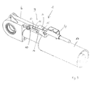
- FIG. 1 In the FIG. 1 is a distributor 3 for the distribution of stored in a storage tank 22 seed / fertilizer shown here for simplicity not shown conveyor and coulters 20 in an agricultural soil.
- the coulters are part of a working device 2 of the distributor 3 and the distributor 3 also has a chassis 21.
- the sowing When turning the distributor 3 at the edge of the field, so on the headland, the sowing is interrupted and the working device 2 is raised so that processing of the soil is avoided. Both that Lifting the working equipment 2 as well as exhibiting the sowing on the headland should be as reliable as possible at the edge of the field. On the other hand, the sowing should not be interrupted by a malfunction of the switching device 1 while driving over the soil.
- FIG. 1 shown embodiment of the distributor 3 The lifting of the working device 2 and thus the coulters 20 away from the soil takes place in the in FIG. 1 shown embodiment of the distributor 3 by rotation of the working device 2 to a arranged on the chassis 21 joint.
- the rotation is effected by the retraction and extension of a here designed as a hydraulic cylinder actuating cylinder 18.
- the actuating cylinder 18 is articulated with its piston rod 19 on the working device 2 articulated, while the cylinder tube 17 of the actuating cylinder 18 is hinged at the opposite end of the actuating cylinder 18 hinged to a support frame 5 of the distributor 3.
- the storage tank 22 and the chassis 21 are mounted on the support frame 5
- the distributor 3 can be coupled via the holding frame 5 with a tractor pulling the distributor 3 in a direction of travel F.
- a retraction of the actuating cylinder 18 causes in the in FIG. 1 3, a lifting of the working device 2 from a first position (FIG. Fig. 2 ) for applying the seed / fertilizer on the field soil to a second position (headland position, Fig. 3 ) for turning at the edge of the field.
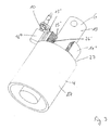
- switching means 9 in the form of a first switching element 4 and a second switching element 6 displaceably guided in the first switching element 4 as well as a switch 10 and a switching sleeve 11 are provided on the adjusting cylinder 18.
- the first switching element 4 is fixed on the holding frame 5 via a contact plate 15 fixed to the cylinder tube 17 without a translatory degree of freedom in the direction of a longitudinal axis 7 of the first switching element 4.
- the cylinder tube 17 is therefore only, as described above, free in the rotational direction to allow the pivoting movement of the working device 2 when raising or lowering.
- the first switching element 4 is designed as a guide tube or sleeve, on the circular cylindrical inner wall, the second switching element 6 is slidably guided with play.
- the second switching element 6, here in the form of a circular cylindrical cross-section rod is fixed to a provided for coupling the piston rod 19 with the working device 2 coupling member 23 on the working device 2, and also without translational degree of freedom in the direction of a longitudinal axis 8 of the second switching element. 6
- the longitudinal axis 8 is aligned in the embodiment shown here with the longitudinal axis 7, since the second switching element 6 is guided in the first switching element 4.
- the second switching element 6 performs a movement corresponding to the movement of the piston rod 19 relative to the cylinder tube 17 with respect to the first switching element 4.
- the movement is also proportional to the movement of the working device 2 relative to the holding frame 5.
- the switching sleeve 11 is with its longitudinal axis 24, which in the in FIG. 2 shown embodiment coincides with the longitudinal axis 7 and the longitudinal axis 8, guided along the second switching member 6 and slidably.
- the frictional connection is made according to FIG. 4 from a friction ring 26, which is inserted into an annular groove 25 on the inner circumference of the shift sleeve 11 and bears against the outer circumference of the second shift member 6.
- the resulting frictional force of the friction joint for example, by providing a plurality of friction rings 26 side by side, can be adapted to the respective needs.
- the friction ring consists in particular of rubber, while the second switching element 6 in particular consists of metal, as well as the switching sleeve 11, which may also be made of plastic.
- a snap ring made of plastic is conceivable according to the invention, or a shift sleeve made of two plastic shells, which are held by screw on the piston and wherein the screw force determines the friction factor.
- the switching means with a pair of materials that performs a friction with each other, but not or only slightly wears / abrasion subject.
- the elongated hole 14 in the switching plate 15, in which the pin 16 is moved during the extension and retraction of the actuating cylinder 18 back and forth, extends parallel to the longitudinal axis 7, longitudinal axis 8 and the longitudinal axis 24th
- the movement of the pin 16 thus always follows at the beginning of a change of direction of the movement of the adjusting cylinder 18, in particular the Piston rod 19 until the pin abuts the opposite stop 12, 13.
- the switch 10 By the switch 10, the first and the second switching state of the pin 16 can be detected, so that immediately at the beginning of a change in direction or after a length of the slot 14 corresponding stroke of the shift sleeve 11 by the second switching element 6 reliable switching of the distributor, in particular sowing into a non-emergency operation.
- the switching takes place at the earliest possible and optimal time, with a time-shifted switching invention is conceivable.
- a path calculation as in the prior art is omitted, whereby the switching device according to the invention works independently. It is even an operation directly through the switch 10 conceivable.
- the invention allows a reliable display of the switching states.
- the switch 10 is preferably designed as an inductive sensor and due to the matching translation direction of the movable components of the switching device 1, a single switch 10 is sufficient for detecting the two switching states of the switching device.
- the switching device 1 according to the present invention is easy to install and has extremely fast reaction times, since extremely short switching paths are made possible. Furthermore, the switching device according to the invention is independent of how large the stroke of the actuating cylinder is in an individual case.
- a less expensive switching plate 15 ' is provided, which is also fixed to the cylinder tube 17 and has an L-shaped basic shape.
- the switch 10 is in contrast to the arrangement of the switch 10 according to FIGS. 3 to 5 arranged rotated by 180 degrees.
- a pin 16 ' for limiting the movement of the switching sleeve 11' in the slot 14 'and a second pin 16 "opposite to the pin 16' on the switching sleeve 11 'arranged on the second pin 16" is detected by the switch 10, the switching state.
- the switching plate 15 ' serves, at the same time as a second switching element 6, by the first switching element 4 in an opening of the switching plate 15' is slidably guided.
- the inventive design of the switching device 1 according to FIGS. 8 and 9 is characterized by the fact that the cylinder tube 17 simultaneously serves as a first switching element 4, while the piston rod 19 is simultaneously provided as a second switching element 6.
- the trained as a switching sleeve 11 "slider is dimensioned correspondingly larger and is taken directly from the piston rod 19 by the shift sleeve 11" surrounds the piston rod 19.
- a switching plate 15 " is attached to an end face 27 of the cylinder tube 17 and provided with a slot 14 ', which is penetrated by a pin 16' as” formed extension of the switching sleeve 11 ".
- the described Schait painen 1 are particularly useful for a circuit in which an adjustment of one or more, in particular connected in series, responsible for increasing the coulter pressure actuating cylinder 18 to increase the coulter pressure, so that the first and second switching state of each actuator cylinder 18 is detected. With the circuit can then be controlled by means of a control device, the seed application, in particular by connecting the switching device to the control device of the tractor.
Landscapes
- Life Sciences & Earth Sciences (AREA)
- Soil Sciences (AREA)
- Environmental Sciences (AREA)
- Fertilizing (AREA)
- Sowing (AREA)
Description
- Die Erfindung betrifft eine Schalteinrichtung mit einem ersten Schaltzustand bei Verstellung einer Arbeitseinrichtung einer landwirtschaftlichen Verteilmaschine von einer ersten Stellung in eine zweite Stellung und mit einem zweiten Schaltzustand bei Rückstellung von der zweiten Stellung in die erste Stellung gemäß Patentanspruch 1. Weiterhin betrifft die vorliegende Erfindung eine Verteilmaschine zur Verteilung von Saatgut/Dünger gemäß Patentanspruch 9.
- Für das Ein- oder Ausschalten elektrisch angetriebener Säaggregate oder Dosiergeräte, wofür der Gegenstand der vorliegenden Erfindung in erster Linie benötigt wird, wenn bei der Ausbringung von Saatgut/Dünger auf das Feld am Feldrand gewendet wird, existieren im Stand der Technik verschiedene Ansätze.
- Die
DE 297 22 396 U1 beschreibt einen Hydraulikzylinder mit einer Kulissenschaltung. - Die
DE 10038595 A1 beschreibt einen Zylinden mit einer Schalteinrichtung für landwirtschaftlichen maschinen. DieDE 10 2008 050 783 A1 beschreibt eine gezogene Sämaschine mit einer durch eine Antriebsvorrichtung angetriebenen Dosiervorrichtung, wobei der Antriebsvorrichtung eine als einen Kolben aufweisende Hydraulikzylinder ausgebildete Abschalteinrichtung zur Unterbrechung des Antriebswellen aufweisenden Antriebes der Dosiervorrichtung zugeordnet ist. - Die europäische Patentschrift
EP 0 650 660 B1 beschreibt die Ein- und Abschaltung der Saatgutausbringung mittels eines Spornrades verbunden mit dem Nachteil, dass das Ein- und Abschalten auf Grund der Trägheit des Systems zeitlich versetzt erfolgt, da das Saatgut erst mit Rotation des Spornrades zu den Säscharen befördert wird. - In der
DE 10 2004 014 063 A9 wird eine Elektronik beschrieben, mit der eine Dosierungssteuerung ein- und ausgeschaltet werden kann. Zur Erkennung, ob sich die Verteilmaschine 1 in Arbeitsstellung A oder in Nichtarbeitsstellung N befindet, werden verschiedene Arten von Sensoren, beispielsweise Näherungsschalter 19, Drehwinkelsensor 17 oder Hubwegsensor 18 vorgeschlagen (siehe [0022] und [0023]). Der Lösungsansatz mit Näherungsschaltern 19 bringt als Nachteil lange Schaltwege mit sich und darüber hinaus wird auf Grund der Starrheit des Systems die Flexibilität eingeschränkt. Bei Änderung der Sätiefe beziehungsweise der Höhe des Aushubs müsste entsprechend auch die Lage der Näherungsschalter angepasst werden. Drehwinkelsensoren oder Hubwegsensoren sind kostenintensiv, insbesondere bei einem etwaigen Sensordefekt. Darüber hinaus setzen die vorgenannten Ansätze eine intelligente Steuerung, insbesondere eine Kommunikation mit dem Schlepper, voraus. - Aufgabe der vorliegenden Erfindung ist es, eine konstruktiv einfache, schlepperunabhängige und äußerst zuverlässige Schalteinrichtung sowie korrespondierende Verteilmaschine anzugeben.
- Diese Aufgabe wird mit den Merkmalen der Ansprüche 1 und 9 gelöst. Vorteilhafte Weiterbildungen der Erfindung sind in den Unteransprüchen angegeben. In den Rahmen der Erfindung fallen auch sämtliche Kombinationen aus zumindest zwei der in der Beschreibung, in den Ansprüchen und/oder den Zeichnungen angegebenen Merkmale. Bei angegebenen Wertebereichen sollen auch innerhalb der genannten Grenzen liegende Werte als Grenzwerte offenbart gelten und in beliebiger Kombination beanspruchbar sein.
- Der Erfindung liegt der Gedanke zugrunde, statt einer aufwendigen Weg-oder Winkelmessung Schaltmittel vorzusehen, die zur Erfassung des ersten und zweiten Schaltzustands gemäß Patentanspruch 1 dienen. Somit kann auf eine aufwendige Erfassung der gesamten Bewegung der Arbeitseinrichtung beim Ein- und Ausklappen beziehungsweise Verstellen von einer ersten Stellung in eine zweite Stellung, insbesondere von einer Vorgewendestellung in eine Arbeitsstellung verzichtet werden. Der Vorteil von Schaltmitteln liegt nicht nur in der kostengünstigeren Herstellung, sondern auch in der zuverlässigeren Arbeitsweise. Die Schalteinrichtung ist insbesondere als Vorgewendeschalteinrichtung ausgebildet.
- Gemäß einer vorteilhaften Ausführungsform der Erfindung ist vorgesehen, dass durch die Schaltmittel, insbesondere mittels eines, vorzugsweise genau eines einzigen, am ersten Schaltglied angebrachten Betätigungsmittels, insbesondere Schalters, vorzugsweise Tasters, eine Relativbewegung des ersten Schaltglieds gegenüber dem zweiten Schaltglied nach einer Richtungsänderung erfassbar ist. Mit der Erfassung der Relativbewegung ist nicht etwa gemeint, dass der Weg oder die Bewegung als solche, beispielsweise die Geschwindigkeit, erfasst wird, sondern vielmehr ein Zustand beziehungsweise die Zustandsänderung, die als erster beziehungsweise zweiter Schaltzustand der Schalteinrichtung erfassbar sind. Die erfindungsgemäße Schalteinrichtung ist demnach darauf beschränkt, eine durch die Richtungsänderung der Relativbewegung des ersten Schaltgliedes gegenüber dem zweiten Schaltglied bewirkte Betätigung des Schaltmittels, insbesondere Betätigungsmittels zu erfassen.
- Gemäß einer weiteren vorteilhaften Ausführungsform der Erfindung ist vorgesehen, dass das erste Schaltglied entlang des zweiten Schaltglieds durch die Schaltmittel, insbesondere mittels eines Gleiters, vorzugsweise einer das zweite Schaltglied zumindest teilweise, insbesondere reibschlüssig, umschließenden Schalthülse, geführt ist. Auf diese Weise kann mit Vorteil auf mechanische Bauteile wie Getriebe, Zahnräder oder sonstige rotierende Bauteile bei den Schaltmitteln gemäß der vorliegenden Erfindung verzichtet werden.
- Soweit durch die Schaltmittel, insbesondere durch das Betätigungsmittel, vorzugsweise den Schalter, die Relativbewegung der Schalthülse gegenüber dem ersten Schaltglied nach einer Richtungsänderung erfassbar ist, können mit Vorteil besonders einfache und zuverlässige Schalter wie Näherungsschalter beziehungsweise -taster vorgesehen werden. Ein weiterer Vorteil liegt darin, dass durch die zusätzliche Schalthülse und die lineare beziehungsweise translatorische Bewegung der Schaltglieder ein einziger Schalter zur Erfassung der Schaltzustände ausreicht.
- Durch die erfindungsgemäße Maßnahme, dass am ersten Schaltglied zwei die Bewegung der Schalthülse mit dem zweiten Schaltglied begrenzende Anschläge, insbesondere gebildet durch ein, vorzugsweise in einem Schaltblech vorgesehenes, Langloch, angebracht sind, wird die Erfindung vorteilhaft weitergebildet.
- Dabei ist es weiterhin von Vorteil, wenn die Schalthülse einen mit den Anschlägen, insbesondere dem Langloch, zusammenwirkenden Fortsatz, insbesondere in Form eines Stiftes, aufweist. Auf diese Weise wird eine konstruktiv einfache und zuverlässige Ermittlung der Schaltzustände ermöglicht.
- Gemäß einer weiteren, vorteilhaften Ausführungsform der Erfindung ist vorgesehen, dass ein Fortsatz oder der oben beschriebene Fortsatz zur Erfassung der Bewegung der Schalthülse durch den Schalter vorgesehen ist.
- Besonders vorteilhaft ist es gemäß einer Ausführungsform der Erfindung, wenn das erste Schaltglied ein Zylinderrohr eines Stellzylinders zur Verstellung der Verteilmaschine zwischen der Arbeitsstellung und der Vorgewendestellung ist oder das erste Schaltglied an diesem angebracht ist. Zusätzlich oder alternativ hierzu ist es außerdem von Vorteil, wenn das zweite Schaltglied eine Kolbenstange des Stellzylinders ist oder an dieser in Richtung der Längsachse des zweiten Schaltglieds ohne translatorischen Freiheitsgrad gekoppelt ist. Auf diese Weise ist die Schalteinrichtung platzsparend und auf konstruktiv einfache Art und Weise sowie unter Ausnutzung von Synergieeffekten zumindest teilweise in für den Betrieb der Verteilmaschine notwendige Stellzylinder integrierbar. Als Stellzylinder kommen insbesondere pneumatische, elektrische, besonders bevorzugt aber hydraulische Zylinder in Frage.
- Die Verteilmaschine gemäß der vorliegenden Erfindung kann verbessert werden, indem die Schalteinrichtung an der Arbeitseinrichtung angeordnet ist, wobei die Arbeitseinrichtung eine Sämaschine oder ein Spuranreißer sein kann.
- Weitere Vorteile, Merkmale und Einzelheiten der Erfindung ergeben sich aus der nachfolgenden Beschreibung bevorzugter Ausführungsbeispiele sowie anhand der Zeichnungen; diese zeigen in:
- Fig. 1
- eine schematische Seitenansicht auf eine erfindungsgemäße Verteilmaschine mit einer erfindungsgemäßen Schalteinrichtung in einer ersten Stellung,
- Fig. 2
- eine perspektivische Ansicht der erfindungsgemäßen Schalteinrichtung in der ersten Stellung,
- Fig. 3
- eine perspektivische Ansicht der Schalteinrichtung gemäß
Figur 2 in einer zweiten Stellung, - Fig. 4
- eine Detailansicht erfindungsgemäßer Schaltmittel gemäß der Ausführungsform aus
Figur 2 und3 , - Fig. 5
- eine schematische Seitenansicht einer weiteren Ausführungsform der erfindungsgemäßen Schalteinrichtung in einer ersten Stellung,
- Fig. 6
- eine Seitenansicht der Schalteinrichtung gemäß
Figur 5 bei Belegungsbeginn von der ersten Stellung in die zweite Stellung, - Fig. 7
- eine Schnittansicht durch die Schaltmittel der Ausführungsform gemäß
Figur 5 und6 , - Fig. 8
- eine perspektivische Darstellung einer weiteren Ausführungsform der erfindungsgemäßen Schalteinrichtung und
- Fig. 9
- eine perspektivische Darstellung der erfindungsgemäßen Schalteinrichtung gemäß
Figur 8 . - In den Figuren sind gleiche oder gleichwirkende Bauteile mit den gleichen Bezugszeichen gekennzeichnet.
- In der
Figur 1 ist eine Verteilmaschine 3 zur Verteilung von in einem Vorratstank 22 bevorrateten Saatgut/Dünger über hier zur Vereinfachung nicht dargestellte Fördereinrichtung und Säschare 20 in einem Ackerboden gezeigt. Die Säschare sind Bestandteil einer Arbeitseinrichtung 2 der Verteilmaschine 3 und die Verteilmaschine 3 weist außerdem ein Fahrwerk 21 auf. - Beim Wenden der Verteilmaschine 3 am Feldrand, also auf dem Vorgewende, wird die Aussaat unterbrochen und die Arbeitseinrichtung 2 angehoben, damit eine Bearbeitung des Ackerbodens vermieden wird. Sowohl das Anheben der Arbeitseinrichtung 2 als auch das Ausstellen der Aussaat auf dem Vorgewende soll möglichst exakt am Feldrand zuverlässig erfolgen. Auf der anderen Seite soll die Aussaat während der Fahrt über den Ackerboden nicht durch eine Fehlfunktion der Schalteinrichtung 1 unterbrochen werden.
- Das Ausheben der Arbeitseinrichtung 2 und damit der Säschare 20 vom Ackerboden weg erfolgt bei der in
Figur 1 gezeigten Ausführung der Verteilmaschine 3 durch Rotation der Arbeitseinrichtung 2 um ein am Fahrwerk 21 angeordnetes Gelenk. Die Rotation wird durch das Ein- und Ausfahren eines hier als Hydraulikzylinder ausgebildeten Stellzylinders 18 bewirkt. Der Stellzylinder 18 ist mit seiner Kolbenstange 19 an der Arbeitseinrichtung 2 gelenkig angeschlagen, während das Zylinderrohr 17 des Stellzylinders 18 am gegenüberliegenden Ende des Stellzylinders 18 gelenkig an einem Halterahmen 5 der Verteilmaschine 3 angeschlagen ist. Am Halterahmen 5 sind außerdem der Vorratstank 22 und das Fahrwerk 21 angebracht Weiterhin ist die Verteilmaschine 3 über den Halterahmen 5 mit einem Schlepper koppelbar, der die Verteilmaschine 3 in einer Fahrtrichtung F zieht. - Ein Einziehen des Stellzylinders 18 bewirkt bei der in
Figur 1 dargestellten Verteilmaschine 3 demnach ein Ausheben der Arbeitseinrichtung 2 von einer ersten Stellung (Fig. 2 ) zur Aufbringung des Saatguts/Düngers auf dem Ackerboden in eine zweite Stellung (Vorgewendestellung,Fig. 3 ) zum Wenden am Feldrand. - Erfindungsgemäß sind an dem Stellzylinder 18 Schaltmittel 9 in Form eines ersten Schaltglieds 4 und eines in dem ersten Schaltglied 4 verschiebbar geführten zweiten Schaltglieds 6 sowie eines Schalters 10 und einer Schalthülse 11 vorgesehen.
- Anhand der
Figuren 2 ,3 und4 wird die Funktion der Schaltmittel 9 beim Verstellen der Arbeitseinrichtung 2 von der inFigur 2 gezeigten ersten Stellung in dieFigur 3 dargestellte zweite Stellung erläutert. - Das erste Schaltglied 4 ist über ein am Zylinderrohr 17 fixiertes Schaltblech 15 am Halterahmen 5 ohne einen translatorischen Freiheitsgrad in Richtung einer Längsachse 7 des ersten Schaltglieds 4 fixiert. Das Zylinderrohr 17 ist also nur, wie oben beschrieben, in Rotationsrichtung frei, um die Schwenkbewegung der Arbeitseinrichtung 2 beim Anheben oder Absenken zuzulassen.
- Das erste Schaltglied 4 ist als Führungsrohr oder -hülse ausgebildet, an deren kreiszylindrischen Innenwand das zweite Schaltglied 6 mit Spiel gleitend geführt ist. Das zweite Schaltglied 6, hier in Form eines im Querschnitt kreiszylindrischen Stabs ist an einem zur Kopplung der Kolbenstange 19 mit der Arbeitseinrichtung 2 vorgesehenen Koppelglied 23 an der Arbeitseinrichtung 2 fixiert, und zwar ebenfalls ohne translatorischen Freiheitsgrad in Richtung einer Längsachse 8 des zweiten Schaltglieds 6. Die Längsachse 8 ist bei dem hier gezeigten Ausführungsbeispiel mit der Längsachse 7 fluchtend, da das zweite Schaltglied 6 in dem ersten Schaltglied 4 geführt ist.
- Das zweite Schaltglied 6 führt demnach gegenüber dem ersten Schaltglied 4 eine mit der Bewegung der Kolbenstange 19 gegenüber dem Zylinderrohr 17 korrespondierende Bewegung aus. Die Bewegung ist außerdem proportional zu der Bewegung der Arbeitseinrichtung 2 gegenüber dem Halterahmen 5.
- Die Schalthülse 11 ist mit ihrer Längsachse 24, die bei der in
Figur 2 gezeigten Ausführungsform mit der Längsachse 7 und der Längsachse 8 zusammenfällt, entlang dem zweiten Schaltglied 6 geführt und verschiebbar. Durch eine reibschlüssige Verbindung zwischen der Schalthülse 11 und dem zweiten Schaltglied 6 nimmt das zweite Schaltglied 6 die Schalthülse 11 bei einer Bewegung des zweiten Schaltglieds 6 mit. Die reibschlüssige Verbindung besteht gemäßFigur 4 aus einem am Innenumfang der Schalthülse 11 in eine Ringnut 25 eingesetzten Reibring 26, der am Außenumfang des zweiten Schaltglieds 6 anliegt. Somit kann die entstehende Reibkraft der Reibverbindung, beispielsweise durch Vorsehen mehrerer Reibringe 26 nebeneinander, an den jeweiligen Bedarf angepasst werden. Der Reibring besteht insbesondere aus Gummi, während das zweite Schaltglied 6 insbesondere aus Metall besteht, ebenso wie die Schalthülse 11, die aber auch aus Kunststoff gefertigt sein kann. - Alternativ zu der Schalthülse 11 ist erfindungsgemäß ein Sprengring aus Kunststoff denkbar, oder eine Schalthülse gefertigt aus zwei Kunststoffschalen, die durch Schraubverbindungen am Kolben gehalten werden und wobei die Schraubkraft den Reibfaktor bestimmt.
- Besonders vorteilhaft ist eine Ausgestaltung der Schaltmittel mit einer Werkstoffpaarung, die eine Reibung untereinander ausführt, aber nicht oder nur unwesentlich verschleißt/Abrieb unterliegt.
- Die Bewegung der Schalthülse 11, die durch das Ein- und Ausfahren des Stellzylinders 18 bewirkt wird, wird durch einen von dem Außenumfang der Schalthülse 11 radial abstehenden Stift 16 in Zusammenwirken mit zwei Anschlägen 12, 13 eines Langlochs 14 im Schaltblech 15 begrenzt. Die durch die Reibverbindung erzeugte Reibkraft der Schalthülse 11 gegenüber dem zweiten Schaltglied 6 wird dabei überwunden.
- Das Langloch 14 in dem Schaltblech 15, in welchem der Stift 16 beim Ein-und Ausfahren des Stellzylinders 18 hin und her bewegt wird, erstreckt sich parallel zur Längsachse 7, Längsachse 8 und Längsachse 24.
- Die Bewegung des Stifts 16 folgt damit immer zu Beginn eines Richtungswechsels der Bewegung des Stellzylinders 18, insbesondere der Kolbenstange 19, bis der Stift am gegenüberliegenden Anschlag 12, 13 anschlägt. Damit ist am Anschlag 12 ein erster Schaltzustand bei Verstellung der Arbeitseinrichtung von der ersten Stellung in die zweite Stellung definiert, während am Anschlag 13 ein zweiter Schaltzustand des Stiftes 16 definiert ist, der bei Rückstellung von der zweiten Stellung in die erste Stellung gemäß
Figur 2 vorliegt. - Durch den Schalter 10 ist der erste und der zweite Schaltzustand des Stifts 16 erfassbar, so dass unmittelbar bei Beginn einer Richtungsänderung beziehungsweise nach einem der Länge des Langlochs 14 entsprechendem Hub der Schalthülse 11 durch das zweite Schaltglied 6 ein zuverlässiges Umschalten der Verteilmaschine, insbesondere vom Säbetrieb in einen Nichtsäbetrieb, ermöglicht wird. Die Umschaltung erfolgt damit zum frühestmöglichen und optimalen Zeitpunkt, wobei auch ein zeitlich versetztes Schalten erfindungsgemäß denkbar ist. Eine Wegberechnung wie im Stand der Technik entfällt, wodurch die erfindungsgemäße Schalteinrichtung unabhängig funktioniert. Es ist sogar eine Betätigung direkt durch den Schalter 10 denkbar. Außerdem ermöglicht die Erfindung eine zuverlässige Anzeige der Schaltzustände.
- Der Schalter 10 ist vorzugsweise als Induktivsensor ausgebildet und auf Grund der übereinstimmenden Translationsrichtung der beweglichen Bauteile der Schalteinrichtung 1 genügt ein einziger Schalter 10 zur Erfassung der beiden Schaltzustände der Schalteinrichtung.
- Die Schalteinrichtung 1 der gemäß der vorliegenden Erfindung ist einfach montierbar und weist äußerst schnelle Reaktionszeigen auf, da extrem kurze Schaltwege ermöglicht werden. Weiterhin ist die erfindungsgemäße Schalteinrichtung unabhängig davon, wie groß der Hub des Stellzylinders im Einzelfall ist.
- Bei der Ausführungsform gemäß
Figur 2 bis 4 erfüllt der Stift 16 gleichzeitig die Funktion der Begrenzung der Gleitbewegung der Schalthülse 11 in Zusammenwirkung mit dem Langloch 14 beziehungsweise den Anschlägen 12, 13 sowie die Funktion der Erfassung der Bewegung der Schalthülse 11 in Zusammenwirken mit dem Schalter 10. - In der in
Figur 5 gezeigten Ausführungsform ist dagegen ein weniger aufwendiges Schaltblech 15' vorgesehen, das ebenfalls an dem Zylinderrohr 17 fixiert ist und eine L-förmige Grundform aufweist. Der Schalter 10 ist im Gegensatz zu der Anordnung des Schalters 10 gemäßFigur 3 bis 5 um 180 Grad gedreht angeordnet. Statt wie inFigur 2 bis 4 einen einzigen Stift 16 vorzusehen, ist in der Ausführungsform gemäßFigur 5 ein Stift 16' zur Begrenzung der Bewegung der Schalthülse 11' im Langloch 14' sowie ein zweiter Stift 16" gegenüberliegend zum Stift 16' an der Schalthülse 11' angeordnet. Am zweiten Stift 16" wird vom Schalter 10 der Schaltzustand erfasst. - Das Schaltblech 15' dient, gleichzeitig als zweites Schaltglied 6, indem das erste Schaltglied 4 in einer Öffnung des Schaltblechs 15' gleitend geführt ist.
- Die erfindungsgemäße Ausführung der Schalteinrichtung 1 gemäß
Figuren 8 und9 zeichnet sich dadurch aus, dass das Zylinderrohr 17 gleichzeitig als erstes Schaltglied 4 dient, während die Kolbenstange 19 gleichzeitig als zweites Schaltglied 6 vorgesehen ist. Die als Schalthülse 11" ausgebildete Gleiter ist entsprechend größer dimensioniert und wird direkt von der Kolbenstange 19 mitgenommen, indem die Schalthülse 11" die Kolbenstange 19 umschließt. InFigur 9 ist zu erkennen, dass eine Ringnut 25' und ein in der Ringnut 25' liegender Reibring 26' an der Kolbenstange 19 eine Reibverbindung bewirken. - Ein Schaltblech 15" ist an einer Stirnseite 27 des Zylinderrohrs 17 angebracht und mit einem Langloch 14' versehen, das von einem als Stift 16'" ausgebildeten Fortsatz der Schalthülse 11" durchsetzt ist.
- Beim Einfahren der Kolbenstange 19 wird die Bewegung der Schalthülse 11" in Richtung der Stirnseite 27 durch einen Anschlag 12' des Langlochs 14' begrenzt, wie in
Figur 8 und9 dargestellt. - In umgekehrter Richtung, also beim Ausfahren der Kolbenstange 19 aus dem Zylinderrohr 17 wird die Schalthülse 11" durch die Reibverbindung mit der Kolbenstange 19 mitgenommen, bis der das Langloch 14' durchsetzende Stift 16'" der Schalthülse 11" am Anschlag 13' des Langlochs 14' anschlägt. Die beiden, durch die Anschläge 12', 13' definierten Schaltpositionen beziehungsweise Zustände der Schalthülse 11" sind durch den Schalter 10 erfassbar.
- Die beschriebenen Schaiteinrichtungen 1 sind insbesondere verwendbar für eine Schaltung, bei der eine Verstellung eines oder mehrerer, insbesondere hintereinander geschalteter, für die Erhöhung des Schardrucks zuständiger Stellzylinder 18 zur Erhöhung des Schardrucks erfolgt, so dass der erste und zweite Schaltzustand jedes Stellzylinders 18 erfasst wird. Mit der Schaltung kann dann mittels einer Steuereinrichtung die Saatgutausbringung gesteuert werden, insbesondere durch Anschließen der Schalteinrichtung an die Steuereinrichtung des Schleppers.
-
- 1
- Schalteinrichtung
- 2
- Arbeitseinrichtung
- 3
- Verteilmaschine
- 4
- erstes Schaltglied
- 5
- Halterahmen
- 6
- zweites Schaltglied
- 7
- Längsachse
- 8
- Längsachse
- 9
- Schaltmittel
- 10
- Schalter
- 11, 11', 11"
- Schalthülse
- 12, 12'
- Anschlag
- 13, 13'
- Anschlag
- 14, 14'
- Langloch
- 15, 15', 15"
- Schaltblech
- 16, 16', 16", 16"'
- Stift
- 17
- Zylinderrohr
- 18
- Stellzylinder
- 19
- Kolbenstange
- 20
- Säschare
- 21
- Fahrwerk
- 22
- Vorratstank
- 23
- Koppelglied
- 24
- Längsachse
- 25, 25'
- Ringnut
- 26, 26'
- Reibring
- 27
- Stirnseite
- F
- Fahrtrichtung
Claims (10)
- Schalteinrichtung (1) für eine landwirtschaftliche Verteilmaschine mit:- einem ersten Schaltzustand bei Verstellung einer Arbeitseinrichtung (2) einer landwirtschaftlichen Verteilmaschine (3) von einer ersten Stellung in eine zweite Stellung,- einem zweiten Schaltzustand bei Rückstellung von der zweiten Stellung in die erste Stellung,- einem ersten Schaltglied (4) zur Fixierung an oder relativ zu einem Halterahmen (5) der Verteilmaschine (3),- einem zweiten Schaltglied (6) zur Fixierung an oder relativ zu der Arbeitseinrichtung (2), das linear, insbesondere translatorisch, vorzugsweise mit seiner Längsachse (8) parallel zu einer Längsachse (7) des ersten Schaltglieds (4), geführt angeordnet ist und- am ersten und/oder zweiten Schaltglied (4, 6) vorgesehenen Schaltmitteln (9) zur Erfassung des ersten und zweiten Schaltzustands,dadurch gekennzeichnet, dass mit der Schalteinrichtung (1) eine durch eine Richtungsänderung der Relativbewegung des ersten Schaltglieds (4) gegenüber dem zweiten Schaltglied (6) bewirkte Betätigung der Schaltmittel (9) erfassbar ist.
- Schalteinrichtung (1) nach Anspruch 1, bei der durch die Schaltmittel (9 mittels eines, vorzugsweise genau eines einzigen, am ersten Schaltglied (4) angebrachten Betätigungsmittels, insbesondere Schalter (10), eine Relativbewegung des ersten Schaltglieds (4) gegenüber dem zweiten Schaltglied (6) nach einer Richtungsänderung erfassbar ist.
- Schalteinrichtung (1) nach einem der vorhergehenden Ansprüche, bei der das erste Schaltglied (4) entlang des zweiten Schaltglieds (6) durch die Schaltmittel (9), insbesondere mittels eines Gleiters, vorzugsweise einer das zweite Schaltglied (6) zumindest teilweise, insbesondere reibschlüssig, umschließenden Schalthülse (11, 11', 11"), gleitend geführt ist.
- Schalteinrichtung (1) nach Anspruch 3, bei der durch die Schaltmittel (9), insbesondere durch das Betätigungsmittels, vorzugsweise den Schalter (10), die Relativbewegung der Schalthülse (11, 11', 11") gegenüber dem ersten Schaltglied (4) nach einer Richtungsänderung erfassbar ist.
- Schalteinrichtung nach Anspruch 4, bei der am ersten Schaltglied (4) zwei die Bewegung der Schalthülse (11, 11', 11") mit dem zweiten Schaltglied (6) begrenzende Anschläge (12, 12', 13, 13'), insbesondere gebildet durch ein, vorzugsweise in einem Schaltblech (15, 15', 15") vorgesehenen, Langloch (14, 14'), angebracht sind.
- Schalteinrichtung nach Anspruch 5, bei der die Schalthülse einen mit den Anschlägen (12, 12', 13, 13'), insbesondere dem Langloch (14, 14'), zusammenwirkenden Fortsatz, insbesondere in Form eines Stiftes (16, 16', 16"), aufweist.
- Schalteinrichtung nach einem der Ansprüche 2 bis 6, bei der ein Fortsatz, insbesondere der Fortsatz gemäß Anspruch 6, zur Erfassung der Bewegung der Schalthülse (11) durch den Sensor (10) vorgesehen ist.
- Schalteinrichtung (1) nach einem der vorhergehenden Ansprüche, bei der- das erste Schaltglied (4) ein Zylinderrohr (17) eines Stellzylinders (18) zur Verstellung der Verteilmaschine (3) zwischen der ersten Stellung und der zweiten Stellung ist oder an diesem angebracht ist und/oder- das zweite Schaltglied (6) eine Kolbenstange (19) des Stellzylinders (18) ist oder an dieser in Richtung der Längsachse (8) des zweiten Schaltglieds (6) ohne translatorischen Freiheitsgrad gekoppelt ist.
- Verteilmaschine (3) mit einer ersten Stellung zur Verteilung von Saatgut/Dünger und einer zweiten Stellung zum Wenden der Verteilmaschine (3), die mindestens eine Schalteinrichtung (1) nach einem der vorhergehenden Ansprüche aufweist.
- Verteilmaschine (3) nach Anspruch 9, bei der Schalteinrichtung (1) an der Arbeitseinrichtung (2) angeordnet ist, wobei die Arbeitseinrichtung (2) eine Sämaschine oder ein Spuranreißer ist.
Priority Applications (1)
| Application Number | Priority Date | Filing Date | Title |
|---|---|---|---|
| PL11166655T PL2401903T3 (pl) | 2010-07-02 | 2011-05-19 | Urządzenie przełącznikowe do rolniczego rozdzielacza do wysiewu ziarna i/lub nawozów |
Applications Claiming Priority (1)
| Application Number | Priority Date | Filing Date | Title |
|---|---|---|---|
| DE102010025944A DE102010025944A1 (de) | 2010-07-02 | 2010-07-02 | Schalteinrichtung für eine landwirtschaftliche Verteilmaschine zum Ausbringen von Saatgut und/oder Dünger |
Publications (2)
| Publication Number | Publication Date |
|---|---|
| EP2401903A1 EP2401903A1 (de) | 2012-01-04 |
| EP2401903B1 true EP2401903B1 (de) | 2013-03-20 |
Family
ID=44117829
Family Applications (1)
| Application Number | Title | Priority Date | Filing Date |
|---|---|---|---|
| EP11166655A Active EP2401903B1 (de) | 2010-07-02 | 2011-05-19 | Schalteinrichtung für eine landwirtschaftliche Verteilmaschine zum Ausbringen von Saatgut und/oder Dünger |
Country Status (5)
| Country | Link |
|---|---|
| EP (1) | EP2401903B1 (de) |
| DE (1) | DE102010025944A1 (de) |
| DK (1) | DK2401903T3 (de) |
| ES (1) | ES2415168T3 (de) |
| PL (1) | PL2401903T3 (de) |
Families Citing this family (3)
| Publication number | Priority date | Publication date | Assignee | Title |
|---|---|---|---|---|
| FR3028379B1 (fr) * | 2014-11-18 | 2017-03-31 | Kuhn Sa | Machine agricole avec un dispositif de commutation a detection angulaire |
| CN107781257B (zh) * | 2017-11-22 | 2023-06-20 | 北京起重运输机械设计研究院有限公司 | 油缸位移检测装置 |
| DE102022110628A1 (de) | 2022-05-02 | 2023-11-02 | Amazonen-Werke H. Dreyer SE & Co. KG | Verfahren zum Steuern der Aushubstellung an einer landwirtschaftlichen Anbaumaschine, Steuersystem und Anbaumaschine |
Citations (1)
| Publication number | Priority date | Publication date | Assignee | Title |
|---|---|---|---|---|
| DE10038595A1 (de) * | 2000-08-08 | 2002-03-28 | Deere & Co | Steuervorrichtung einer Koppelstange |
Family Cites Families (8)
| Publication number | Priority date | Publication date | Assignee | Title |
|---|---|---|---|---|
| DE2701691C2 (de) * | 1977-01-17 | 1979-02-22 | A.J. Troester Gmbh & Co Kg, 6308 Butzbach | Drillmaschine |
| EP0281761B1 (de) * | 1987-02-12 | 1991-06-12 | Amazonen-Werke H. Dreyer GmbH & Co. KG | Einzelkorndrillmaschine |
| DE3709526A1 (de) * | 1987-03-25 | 1988-10-13 | Amazonen Werke Dreyer H | Verteilmaschine |
| DE9316622U1 (de) | 1993-11-02 | 1994-01-05 | Rabewerk Gmbh + Co, 49152 Bad Essen | Verteilmaschine zum Ausbringen eines Verteilgutes |
| US5896966A (en) * | 1997-05-02 | 1999-04-27 | Schmelzle; Douglas Martin | Hydraulic seed clutch actuator for seed drills |
| DE29722396U1 (de) * | 1997-12-18 | 1998-10-22 | Wilhelm Karmann GmbH, 49084 Osnabrück | Hydraulikzylinder |
| DE102004014063A1 (de) * | 2004-03-23 | 2005-10-13 | Rabe Agrarsysteme Gmbh & Co. Kg | Verteilmaschine zum Ausbringen von Verteilgütern |
| DE102008050783A1 (de) * | 2008-10-08 | 2010-04-15 | Amazonen-Werke H. Dreyer Gmbh & Co. Kg | Gezogene Sämaschine |
-
2010
- 2010-07-02 DE DE102010025944A patent/DE102010025944A1/de not_active Withdrawn
-
2011
- 2011-05-19 ES ES11166655T patent/ES2415168T3/es active Active
- 2011-05-19 PL PL11166655T patent/PL2401903T3/pl unknown
- 2011-05-19 DK DK11166655.8T patent/DK2401903T3/da active
- 2011-05-19 EP EP11166655A patent/EP2401903B1/de active Active
Patent Citations (1)
| Publication number | Priority date | Publication date | Assignee | Title |
|---|---|---|---|---|
| DE10038595A1 (de) * | 2000-08-08 | 2002-03-28 | Deere & Co | Steuervorrichtung einer Koppelstange |
Also Published As
| Publication number | Publication date |
|---|---|
| PL2401903T3 (pl) | 2013-08-30 |
| EP2401903A1 (de) | 2012-01-04 |
| ES2415168T3 (es) | 2013-07-24 |
| DK2401903T3 (da) | 2013-06-17 |
| DE102010025944A1 (de) | 2012-01-05 |
Similar Documents
| Publication | Publication Date | Title |
|---|---|---|
| EP2305068B1 (de) | Ausstossvorrichtung für ein bewegbares Möbelteil | |
| EP2919574B1 (de) | Abstreifeinrichtung, säherz und einzelkornsämaschine | |
| DE102013112813A1 (de) | Sensoreinrichtung und Scheibenbremse mit einer Sensoreinrichtung | |
| EP2401903B1 (de) | Schalteinrichtung für eine landwirtschaftliche Verteilmaschine zum Ausbringen von Saatgut und/oder Dünger | |
| EP2776267B1 (de) | Fahrzeug-steuerungsvorrichtung | |
| EP3918898B1 (de) | Landwirtschaftliche maschine | |
| DE102008024132B4 (de) | Spoilerantrieb mit Zwischenstellungen | |
| DE3117850C2 (de) | ||
| DE102020002780B3 (de) | Pipette und Verfahren zum Betreiben einer Pipette | |
| EP1381554B1 (de) | Wendestange | |
| DE102019107585A1 (de) | Verteilergetriebe mit bereichs- und betriebsartbetätiger, der einen nockenstösselmechanismus zur überwindung blockierter schaltereignisse und eine die erfassung von gabelpositionen ermöglichende sensorkonfiguration aufweist | |
| EP2947353B1 (de) | Triebachse für ein fahrzeug | |
| DE3017415C2 (de) | Steuersystem für Drillmaschinen | |
| DE102012002122A1 (de) | Verriegelungsvorrichtung für einen Teleskopausleger | |
| EP2017798B1 (de) | Vorrichtung zum Auszahlen von Münzen aus einem Paar benachbarter Münztuben | |
| EP0210426A1 (de) | Fernbetätigungsvorrichtung | |
| DE2626027B2 (de) | Schwenklager für einen Kamerastativkopf | |
| EP1304495B1 (de) | Drehmomentbegrenzungskupplung | |
| DE102018216741A1 (de) | Integrierte Funktionseinheit | |
| DE102014011501B4 (de) | Hebelschalter für ein Kraftfahrzeug | |
| DE102015210129A1 (de) | Hydraulisches Ventil mit verstellbarer Rastvorrichtung | |
| EP2119336B1 (de) | Dosiereinrichtung | |
| DE3616538A1 (de) | Pneumatikstreuer | |
| EP1886858A2 (de) | Winkelgeber mit Montageöffnung | |
| EP4324317A1 (de) | Dosierer zum dosieren von dosiergut |
Legal Events
| Date | Code | Title | Description |
|---|---|---|---|
| 17P | Request for examination filed |
Effective date: 20111013 |
|
| AK | Designated contracting states |
Kind code of ref document: A1 Designated state(s): AL AT BE BG CH CY CZ DE DK EE ES FI FR GB GR HR HU IE IS IT LI LT LU LV MC MK MT NL NO PL PT RO RS SE SI SK SM TR |
|
| AX | Request for extension of the european patent |
Extension state: BA ME |
|
| PUAI | Public reference made under article 153(3) epc to a published international application that has entered the european phase |
Free format text: ORIGINAL CODE: 0009012 |
|
| 17Q | First examination report despatched |
Effective date: 20120312 |
|
| GRAP | Despatch of communication of intention to grant a patent |
Free format text: ORIGINAL CODE: EPIDOSNIGR1 |
|
| GRAS | Grant fee paid |
Free format text: ORIGINAL CODE: EPIDOSNIGR3 |
|
| GRAA | (expected) grant |
Free format text: ORIGINAL CODE: 0009210 |
|
| AK | Designated contracting states |
Kind code of ref document: B1 Designated state(s): AL AT BE BG CH CY CZ DE DK EE ES FI FR GB GR HR HU IE IS IT LI LT LU LV MC MK MT NL NO PL PT RO RS SE SI SK SM TR |
|
| RAP1 | Party data changed (applicant data changed or rights of an application transferred) |
Owner name: KVERNELAND A/S |
|
| REG | Reference to a national code |
Ref country code: GB Ref legal event code: FG4D Free format text: NOT ENGLISH |
|
| REG | Reference to a national code |
Ref country code: CH Ref legal event code: EP |
|
| REG | Reference to a national code |
Ref country code: IE Ref legal event code: FG4D Free format text: LANGUAGE OF EP DOCUMENT: GERMAN |
|
| REG | Reference to a national code |
Ref country code: AT Ref legal event code: REF Ref document number: 601462 Country of ref document: AT Kind code of ref document: T Effective date: 20130415 |
|
| REG | Reference to a national code |
Ref country code: DE Ref legal event code: R096 Ref document number: 502011000505 Country of ref document: DE Effective date: 20130516 |
|
| REG | Reference to a national code |
Ref country code: DK Ref legal event code: T3 |
|
| REG | Reference to a national code |
Ref country code: SE Ref legal event code: TRGR |
|
| REG | Reference to a national code |
Ref country code: ES Ref legal event code: FG2A Ref document number: 2415168 Country of ref document: ES Kind code of ref document: T3 Effective date: 20130724 |
|
| PG25 | Lapsed in a contracting state [announced via postgrant information from national office to epo] |
Ref country code: NO Free format text: LAPSE BECAUSE OF FAILURE TO SUBMIT A TRANSLATION OF THE DESCRIPTION OR TO PAY THE FEE WITHIN THE PRESCRIBED TIME-LIMIT Effective date: 20130620 Ref country code: LT Free format text: LAPSE BECAUSE OF FAILURE TO SUBMIT A TRANSLATION OF THE DESCRIPTION OR TO PAY THE FEE WITHIN THE PRESCRIBED TIME-LIMIT Effective date: 20130320 Ref country code: BG Free format text: LAPSE BECAUSE OF FAILURE TO SUBMIT A TRANSLATION OF THE DESCRIPTION OR TO PAY THE FEE WITHIN THE PRESCRIBED TIME-LIMIT Effective date: 20130620 |
|
| REG | Reference to a national code |
Ref country code: SK Ref legal event code: T3 Ref document number: E 14139 Country of ref document: SK |
|
| REG | Reference to a national code |
Ref country code: LT Ref legal event code: MG4D |
|
| PG25 | Lapsed in a contracting state [announced via postgrant information from national office to epo] |
Ref country code: SI Free format text: LAPSE BECAUSE OF FAILURE TO SUBMIT A TRANSLATION OF THE DESCRIPTION OR TO PAY THE FEE WITHIN THE PRESCRIBED TIME-LIMIT Effective date: 20130320 Ref country code: FI Free format text: LAPSE BECAUSE OF FAILURE TO SUBMIT A TRANSLATION OF THE DESCRIPTION OR TO PAY THE FEE WITHIN THE PRESCRIBED TIME-LIMIT Effective date: 20130320 Ref country code: LV Free format text: LAPSE BECAUSE OF FAILURE TO SUBMIT A TRANSLATION OF THE DESCRIPTION OR TO PAY THE FEE WITHIN THE PRESCRIBED TIME-LIMIT Effective date: 20130320 Ref country code: GR Free format text: LAPSE BECAUSE OF FAILURE TO SUBMIT A TRANSLATION OF THE DESCRIPTION OR TO PAY THE FEE WITHIN THE PRESCRIBED TIME-LIMIT Effective date: 20130621 |
|
| REG | Reference to a national code |
Ref country code: PL Ref legal event code: T3 |
|
| REG | Reference to a national code |
Ref country code: NL Ref legal event code: VDEP Effective date: 20130320 |
|
| PG25 | Lapsed in a contracting state [announced via postgrant information from national office to epo] |
Ref country code: HR Free format text: LAPSE BECAUSE OF FAILURE TO SUBMIT A TRANSLATION OF THE DESCRIPTION OR TO PAY THE FEE WITHIN THE PRESCRIBED TIME-LIMIT Effective date: 20130320 Ref country code: RS Free format text: LAPSE BECAUSE OF FAILURE TO SUBMIT A TRANSLATION OF THE DESCRIPTION OR TO PAY THE FEE WITHIN THE PRESCRIBED TIME-LIMIT Effective date: 20130320 |
|
| PG25 | Lapsed in a contracting state [announced via postgrant information from national office to epo] |
Ref country code: RO Free format text: LAPSE BECAUSE OF FAILURE TO SUBMIT A TRANSLATION OF THE DESCRIPTION OR TO PAY THE FEE WITHIN THE PRESCRIBED TIME-LIMIT Effective date: 20130320 Ref country code: EE Free format text: LAPSE BECAUSE OF FAILURE TO SUBMIT A TRANSLATION OF THE DESCRIPTION OR TO PAY THE FEE WITHIN THE PRESCRIBED TIME-LIMIT Effective date: 20130320 Ref country code: PT Free format text: LAPSE BECAUSE OF FAILURE TO SUBMIT A TRANSLATION OF THE DESCRIPTION OR TO PAY THE FEE WITHIN THE PRESCRIBED TIME-LIMIT Effective date: 20130722 Ref country code: IS Free format text: LAPSE BECAUSE OF FAILURE TO SUBMIT A TRANSLATION OF THE DESCRIPTION OR TO PAY THE FEE WITHIN THE PRESCRIBED TIME-LIMIT Effective date: 20130720 Ref country code: NL Free format text: LAPSE BECAUSE OF FAILURE TO SUBMIT A TRANSLATION OF THE DESCRIPTION OR TO PAY THE FEE WITHIN THE PRESCRIBED TIME-LIMIT Effective date: 20130320 |
|
| PG25 | Lapsed in a contracting state [announced via postgrant information from national office to epo] |
Ref country code: CY Free format text: LAPSE BECAUSE OF FAILURE TO SUBMIT A TRANSLATION OF THE DESCRIPTION OR TO PAY THE FEE WITHIN THE PRESCRIBED TIME-LIMIT Effective date: 20130320 |
|
| PG25 | Lapsed in a contracting state [announced via postgrant information from national office to epo] |
Ref country code: MC Free format text: LAPSE BECAUSE OF FAILURE TO SUBMIT A TRANSLATION OF THE DESCRIPTION OR TO PAY THE FEE WITHIN THE PRESCRIBED TIME-LIMIT Effective date: 20130320 |
|
| PLBE | No opposition filed within time limit |
Free format text: ORIGINAL CODE: 0009261 |
|
| STAA | Information on the status of an ep patent application or granted ep patent |
Free format text: STATUS: NO OPPOSITION FILED WITHIN TIME LIMIT |
|
| REG | Reference to a national code |
Ref country code: HU Ref legal event code: AG4A Ref document number: E018065 Country of ref document: HU |
|
| 26N | No opposition filed |
Effective date: 20140102 |
|
| REG | Reference to a national code |
Ref country code: IE Ref legal event code: MM4A |
|
| REG | Reference to a national code |
Ref country code: DE Ref legal event code: R097 Ref document number: 502011000505 Country of ref document: DE Effective date: 20140102 |
|
| PG25 | Lapsed in a contracting state [announced via postgrant information from national office to epo] |
Ref country code: IE Free format text: LAPSE BECAUSE OF NON-PAYMENT OF DUE FEES Effective date: 20130519 |
|
| REG | Reference to a national code |
Ref country code: NL Ref legal event code: RD1H Effective date: 20140623 |
|
| REG | Reference to a national code |
Ref country code: NL Ref legal event code: RD2H Effective date: 20141113 |
|
| REG | Reference to a national code |
Ref country code: CH Ref legal event code: PL |
|
| REG | Reference to a national code |
Ref country code: NL Ref legal event code: RDX Effective date: 20141229 Ref country code: NL Ref legal event code: RD1H Effective date: 20140623 |
|
| PG25 | Lapsed in a contracting state [announced via postgrant information from national office to epo] |
Ref country code: LI Free format text: LAPSE BECAUSE OF NON-PAYMENT OF DUE FEES Effective date: 20140531 Ref country code: CH Free format text: LAPSE BECAUSE OF NON-PAYMENT OF DUE FEES Effective date: 20140531 |
|
| PG25 | Lapsed in a contracting state [announced via postgrant information from national office to epo] |
Ref country code: MT Free format text: LAPSE BECAUSE OF FAILURE TO SUBMIT A TRANSLATION OF THE DESCRIPTION OR TO PAY THE FEE WITHIN THE PRESCRIBED TIME-LIMIT Effective date: 20130320 |
|
| REG | Reference to a national code |
Ref country code: NL Ref legal event code: T3 Ref country code: NL Ref legal event code: RD2H Effective date: 20141113 |
|
| PG25 | Lapsed in a contracting state [announced via postgrant information from national office to epo] |
Ref country code: SM Free format text: LAPSE BECAUSE OF FAILURE TO SUBMIT A TRANSLATION OF THE DESCRIPTION OR TO PAY THE FEE WITHIN THE PRESCRIBED TIME-LIMIT Effective date: 20130320 |
|
| PG25 | Lapsed in a contracting state [announced via postgrant information from national office to epo] |
Ref country code: TR Free format text: LAPSE BECAUSE OF FAILURE TO SUBMIT A TRANSLATION OF THE DESCRIPTION OR TO PAY THE FEE WITHIN THE PRESCRIBED TIME-LIMIT Effective date: 20130320 |
|
| PG25 | Lapsed in a contracting state [announced via postgrant information from national office to epo] |
Ref country code: LU Free format text: LAPSE BECAUSE OF NON-PAYMENT OF DUE FEES Effective date: 20130519 Ref country code: MK Free format text: LAPSE BECAUSE OF FAILURE TO SUBMIT A TRANSLATION OF THE DESCRIPTION OR TO PAY THE FEE WITHIN THE PRESCRIBED TIME-LIMIT Effective date: 20130320 |
|
| REG | Reference to a national code |
Ref country code: FR Ref legal event code: PLFP Year of fee payment: 6 |
|
| REG | Reference to a national code |
Ref country code: FR Ref legal event code: PLFP Year of fee payment: 7 |
|
| REG | Reference to a national code |
Ref country code: FR Ref legal event code: PLFP Year of fee payment: 8 |
|
| PGFP | Annual fee paid to national office [announced via postgrant information from national office to epo] |
Ref country code: HU Payment date: 20180515 Year of fee payment: 8 |
|
| PG25 | Lapsed in a contracting state [announced via postgrant information from national office to epo] |
Ref country code: AL Free format text: LAPSE BECAUSE OF FAILURE TO SUBMIT A TRANSLATION OF THE DESCRIPTION OR TO PAY THE FEE WITHIN THE PRESCRIBED TIME-LIMIT Effective date: 20130320 |
|
| PG25 | Lapsed in a contracting state [announced via postgrant information from national office to epo] |
Ref country code: NL Free format text: LAPSE BECAUSE OF FAILURE TO SUBMIT A TRANSLATION OF THE DESCRIPTION OR TO PAY THE FEE WITHIN THE PRESCRIBED TIME-LIMIT Effective date: 20130320 |
|
| PGRI | Patent reinstated in contracting state [announced from national office to epo] |
Ref country code: NL Effective date: 20141119 |
|
| PG25 | Lapsed in a contracting state [announced via postgrant information from national office to epo] |
Ref country code: HU Free format text: LAPSE BECAUSE OF NON-PAYMENT OF DUE FEES Effective date: 20190520 |
|
| PGFP | Annual fee paid to national office [announced via postgrant information from national office to epo] |
Ref country code: CZ Payment date: 20200519 Year of fee payment: 10 Ref country code: DK Payment date: 20200527 Year of fee payment: 10 Ref country code: NL Payment date: 20200527 Year of fee payment: 10 |
|
| PGFP | Annual fee paid to national office [announced via postgrant information from national office to epo] |
Ref country code: GB Payment date: 20200527 Year of fee payment: 10 Ref country code: IT Payment date: 20200528 Year of fee payment: 10 Ref country code: BE Payment date: 20200527 Year of fee payment: 10 Ref country code: SK Payment date: 20200518 Year of fee payment: 10 Ref country code: SE Payment date: 20200527 Year of fee payment: 10 |
|
| PGFP | Annual fee paid to national office [announced via postgrant information from national office to epo] |
Ref country code: AT Payment date: 20200522 Year of fee payment: 10 |
|
| PGFP | Annual fee paid to national office [announced via postgrant information from national office to epo] |
Ref country code: ES Payment date: 20200728 Year of fee payment: 10 |
|
| REG | Reference to a national code |
Ref country code: DE Ref legal event code: R082 Ref document number: 502011000505 Country of ref document: DE Representative=s name: PATENTANWAELTE BECKER & MUELLER, DE Ref country code: DE Ref legal event code: R082 Ref document number: 502011000505 Country of ref document: DE Representative=s name: KILBURN & STRODE LLP, NL |
|
| REG | Reference to a national code |
Ref country code: DK Ref legal event code: EBP Effective date: 20210531 |
|
| REG | Reference to a national code |
Ref country code: SE Ref legal event code: EUG |
|
| REG | Reference to a national code |
Ref country code: NL Ref legal event code: MM Effective date: 20210601 |
|
| REG | Reference to a national code |
Ref country code: AT Ref legal event code: MM01 Ref document number: 601462 Country of ref document: AT Kind code of ref document: T Effective date: 20210519 |
|
| GBPC | Gb: european patent ceased through non-payment of renewal fee |
Effective date: 20210519 |
|
| REG | Reference to a national code |
Ref country code: SK Ref legal event code: MM4A Ref document number: E 14139 Country of ref document: SK Effective date: 20210519 |
|
| PG25 | Lapsed in a contracting state [announced via postgrant information from national office to epo] |
Ref country code: SK Free format text: LAPSE BECAUSE OF NON-PAYMENT OF DUE FEES Effective date: 20210519 Ref country code: SE Free format text: LAPSE BECAUSE OF NON-PAYMENT OF DUE FEES Effective date: 20210520 Ref country code: CZ Free format text: LAPSE BECAUSE OF NON-PAYMENT OF DUE FEES Effective date: 20210519 Ref country code: AT Free format text: LAPSE BECAUSE OF NON-PAYMENT OF DUE FEES Effective date: 20210519 |
|
| REG | Reference to a national code |
Ref country code: BE Ref legal event code: MM Effective date: 20210531 |
|
| PG25 | Lapsed in a contracting state [announced via postgrant information from national office to epo] |
Ref country code: IT Free format text: LAPSE BECAUSE OF NON-PAYMENT OF DUE FEES Effective date: 20210519 Ref country code: GB Free format text: LAPSE BECAUSE OF NON-PAYMENT OF DUE FEES Effective date: 20210519 Ref country code: DK Free format text: LAPSE BECAUSE OF NON-PAYMENT OF DUE FEES Effective date: 20210531 |
|
| PG25 | Lapsed in a contracting state [announced via postgrant information from national office to epo] |
Ref country code: NL Free format text: LAPSE BECAUSE OF FAILURE TO SUBMIT A TRANSLATION OF THE DESCRIPTION OR TO PAY THE FEE WITHIN THE PRESCRIBED TIME-LIMIT Effective date: 20210601 |
|
| PG25 | Lapsed in a contracting state [announced via postgrant information from national office to epo] |
Ref country code: BE Free format text: LAPSE BECAUSE OF NON-PAYMENT OF DUE FEES Effective date: 20210531 |
|
| REG | Reference to a national code |
Ref country code: ES Ref legal event code: FD2A Effective date: 20220804 |
|
| REG | Reference to a national code |
Ref country code: DE Ref legal event code: R081 Ref document number: 502011000505 Country of ref document: DE Owner name: KVERNELAND GROUP SOEST GMBH, DE Free format text: FORMER OWNER: KVERNELAND A/S, KVERNALAND, NO Ref country code: DE Ref legal event code: R082 Ref document number: 502011000505 Country of ref document: DE Representative=s name: PATENTANWAELTE BECKER & MUELLER, DE |
|
| REG | Reference to a national code |
Ref country code: DE Ref legal event code: R082 Ref document number: 502011000505 Country of ref document: DE |
|
| PG25 | Lapsed in a contracting state [announced via postgrant information from national office to epo] |
Ref country code: ES Free format text: LAPSE BECAUSE OF NON-PAYMENT OF DUE FEES Effective date: 20210520 |
|
| P01 | Opt-out of the competence of the unified patent court (upc) registered |
Effective date: 20230525 |
|
| PGFP | Annual fee paid to national office [announced via postgrant information from national office to epo] |
Ref country code: PL Payment date: 20250509 Year of fee payment: 15 Ref country code: DE Payment date: 20250521 Year of fee payment: 15 |
|
| PGFP | Annual fee paid to national office [announced via postgrant information from national office to epo] |
Ref country code: FR Payment date: 20250528 Year of fee payment: 15 |