EP2402117A1 - Ölimpuls-Drehwerkzeug - Google Patents
Ölimpuls-Drehwerkzeug Download PDFInfo
- Publication number
- EP2402117A1 EP2402117A1 EP11168923A EP11168923A EP2402117A1 EP 2402117 A1 EP2402117 A1 EP 2402117A1 EP 11168923 A EP11168923 A EP 11168923A EP 11168923 A EP11168923 A EP 11168923A EP 2402117 A1 EP2402117 A1 EP 2402117A1
- Authority
- EP
- European Patent Office
- Prior art keywords
- oil pulse
- sleeve body
- coupling body
- rotary tool
- ball
- Prior art date
- Legal status (The legal status is an assumption and is not a legal conclusion. Google has not performed a legal analysis and makes no representation as to the accuracy of the status listed.)
- Granted
Links
Images

Classifications
-
- B—PERFORMING OPERATIONS; TRANSPORTING
- B25—HAND TOOLS; PORTABLE POWER-DRIVEN TOOLS; MANIPULATORS
- B25B—TOOLS OR BENCH DEVICES NOT OTHERWISE PROVIDED FOR, FOR FASTENING, CONNECTING, DISENGAGING OR HOLDING
- B25B21/00—Portable power-driven screw or nut setting or loosening tools; Attachments for drilling apparatus serving the same purpose
- B25B21/02—Portable power-driven screw or nut setting or loosening tools; Attachments for drilling apparatus serving the same purpose with means for imparting impact to screwdriver blade or nut socket
-
- B—PERFORMING OPERATIONS; TRANSPORTING
- B25—HAND TOOLS; PORTABLE POWER-DRIVEN TOOLS; MANIPULATORS
- B25B—TOOLS OR BENCH DEVICES NOT OTHERWISE PROVIDED FOR, FOR FASTENING, CONNECTING, DISENGAGING OR HOLDING
- B25B23/00—Details of, or accessories for, spanners, wrenches, screwdrivers
- B25B23/14—Arrangement of torque limiters or torque indicators in wrenches or screwdrivers
- B25B23/1405—Arrangement of torque limiters or torque indicators in wrenches or screwdrivers for impact wrenches or screwdrivers
-
- B—PERFORMING OPERATIONS; TRANSPORTING
- B25—HAND TOOLS; PORTABLE POWER-DRIVEN TOOLS; MANIPULATORS
- B25B—TOOLS OR BENCH DEVICES NOT OTHERWISE PROVIDED FOR, FOR FASTENING, CONNECTING, DISENGAGING OR HOLDING
- B25B23/00—Details of, or accessories for, spanners, wrenches, screwdrivers
- B25B23/14—Arrangement of torque limiters or torque indicators in wrenches or screwdrivers
- B25B23/147—Arrangement of torque limiters or torque indicators in wrenches or screwdrivers specially adapted for electrically operated wrenches or screwdrivers
- B25B23/1475—Arrangement of torque limiters or torque indicators in wrenches or screwdrivers specially adapted for electrically operated wrenches or screwdrivers for impact wrenches or screwdrivers
-
- B—PERFORMING OPERATIONS; TRANSPORTING
- B25—HAND TOOLS; PORTABLE POWER-DRIVEN TOOLS; MANIPULATORS
- B25D—PERCUSSIVE TOOLS
- B25D9/00—Portable percussive tools with fluid-pressure drive, i.e. driven directly by fluids, e.g. having several percussive tool bits operated simultaneously
Definitions
- the sleeve body is integrally coupled to the oil pulse generator, externally mounted on and coaxially with a center shaft portion, which is provided to project from a center of rotation of the output portion with a bearing interposed between the sleeve body and the center shaft portion.
- the coupling body is externally mounted on and coaxially with the sleeve body so as to be rotatable together with the output portion and axially movable.
- the ball is fitted between an outer surface of the sleeve body and an inner surface of the coupling body across the outer surface of the sleeve body and the inner surface of the coupling body.
- the length of the housing in the front-rear direction can be reduced unlike in the case where the coil spring aligned with the oil pulse generator is provided on the side of the final stage of the speed reduction mechanism in the rear of the oil pulse generator. Accordingly, it is possible to suppress an increase in the overall length of the oil pulse rotary tool including the housing.
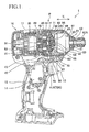
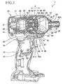
- the motor 30 is disposed in the rear portion of the body portion 11 (on the left side in FIGS. 1 and 3 ).
- the planetary gear speed reduction mechanism 40 is disposed in front of the motor 30 in the body portion 11 (on the right side in FIGS. 1 and 3 ).
- the planetary gear speed reduction mechanism 40 includes a carrier 41, a pinion 42, planetary gears 43, 43, a center shaft portion 44, and an internal gear 45.
- the carrier 41 is rotatably journaled on an inner surface of a gear housing 52 through a ball bearing 51.
- the pinion 42 is secured to an output shaft 31 of the motor 30, and rotatably journaled on the gear housing 52 through a ball bearing 53.
- the carrier 41 is externally mounted on the pinion 42.
- the planetary gears 43, 43 are journaled on the carrier 41 to mesh with the pinion 42.
- the internal gear 45 is fixed in the gear housing 52 to mesh with the planetary gears 43, 43.
- the carrier 41 is an example of the output portion according to the present invention.
- the handle portion 12 is provided continuously from the body portion 11 to form a generally T-shape as the oil pulse driver 1 is viewed from a side surface.
- a switch 14 having a trigger 13 is accommodated inside the handle portion 12. When the trigger 13 is pulled, electric power is supplied to drive the motor 30.
- the unit case 20 is disposed in front of the gear housing 52 (on the right side in FIGS. 1 and 3 ) to be assembled to the front of the body portion 11 (on the right side in FIGS. 1 and 3 ).
- An oil unit 60 is accommodated inside the unit case 20 which is positioned in front of the gear housing 52. Therefore, the oil unit 60 is disposed in front of and coaxially with the carrier 41 which is accommodated in the gear housing 52.
- the oil unit 60 is an example of the oil pulse generator according to the present invention.
- the housing 10 and the unit case 20 are an example of the housing according to the present invention.
- a coupling ring 70 is externally mounted on and coaxially with the sleeve body 63 so as to be movable.
- Cam teeth 70A (see FIGS. 1 and 3 ) are provided to project from the rear end surface of the coupling ring 70 (on the left side in FIGS. 1 to 3 ).
- Cam teeth 41A (see FIGS. 1 and 3 ) are provided to project from the front end surface of the carrier 41 (on the right side in FIGS. 1 to 3 ) so as to oppose the cam teeth 70A.
- the cam teeth 70A is meshed with the cam teeth 41A in the circumferential direction of the coupling ring 70 and the carrier 41, the carrier 41 and the coupling ring 70 can be integrally coupled to each other. Therefore, the coupling ring 70 is rotatable together with the carrier 41.
- the coupling ring 70 is an example of the coupling body according to the present invention.
- Recessed grooves 71, 71 are reversed L-shaped in plan view, and formed in an inner surface of the coupling ring 70.
- cam grooves 68, 68 are L-shaped in plan view, and provided to be recessed in an outer surface of the sleeve body 63.
- the cam grooves 68, 68 are inclined from the center axis side of the sleeve body 63 toward the outer surface side of the sleeve body 63.
- Balls 80 are fitted between the inner surface of the coupling ring 70 and the outer surface of the sleeve body 63 across the recessed grooves 71, 71 and the cam grooves 68, 68.
- the shaft 62 rotates together with the main body 61 until a predetermined torque is reached.
- a predetermined torque is reached.
- an exceeded load of the predetermined torque is applied to the shaft 62, it causes a difference in rotational speed between the shaft 62 and the main body 61. Therefore, a large torque is transmitted to the shaft 62 because of the hydraulic pressure of hydraulic oil accumulated inside the main body 61 as is well known.
- the shaft 62 is rotatably journaled on an inner surface of the unit case 20 through a ball bearing 21 to project from the front end of the unit case 20 to forward the unit case 20.
- a chuck 62A is provided at the distal end of the shaft 62, and where a bit can be mounted.
- the delay in rotation of the shaft 62 discussed above decreases the rotational speed of the sleeve body 63. Therefore, it causes a difference in rotational speed between the sleeve body 63 and the coupling ring 70 which is to rotate at the same speed as the sleeve body 63.
- the balls 80, 80 roll forward in the center axis direction X along the inclined portions of each of the cam grooves 68 while being engaged with each of the recessed grooves 71.
- the coupling ring 70 causes the coupling ring 70 to contract the coil spring 85 against the urging force of the coil spring 85 and to be pressed forward in the center axis direction X as shown in FIG.
- the coupling ring 70 is urged by a compressive force accumulated in the coil spring 85 to return to the retracted position P.
- the balls 80, 80 roll rearward in the center axis direction X along the inclined portions of the cam grooves 68 while being engaged with each of the recessed grooves 71.
- the impact torque is buffered in accordance with the compressive force accumulated in the coil spring 85. Therefore, it prevents reaction to the planetary gear speed reduction mechanism 40, the motor 30, and the housing 10. Hence, it is possible to prevent damage to the planetary gear speed reduction mechanism 40 and the motor 30, and to suppress transmission of vibration to a hand of the user through the housing 10 (handle portion 12) during the screwing operation.
- the needle bearing 65 is disposed between the hollow portion 64 of the sleeve body 63 and the front portion of the center shaft portion 44 of the carrier 40 in the center axis direction X of the sleeve body 63
- the ball bearing 66 is disposed between the hollow portion 64 of the rear portion of the center shaft portion 44 in the center axis direction X. Therefore, the needle bearing 65 and the ball bearing 66 absorb a radial load, which prevent the center shaft portion 44 from excessively interfering with the sleeve body 63.
- the ball bearing 66 can also absorb a thrust load.
- the present invention is applied to the oil pulse driver 1.
- the present invention may be applied to an oil pulse wrench or the like.
Landscapes
- Engineering & Computer Science (AREA)
- Mechanical Engineering (AREA)
- Details Of Spanners, Wrenches, And Screw Drivers And Accessories (AREA)
- Drilling And Boring (AREA)
- One-Way And Automatic Clutches, And Combinations Of Different Clutches (AREA)
- Retarders (AREA)
Applications Claiming Priority (1)
| Application Number | Priority Date | Filing Date | Title |
|---|---|---|---|
| JP2010152338A JP5463221B2 (ja) | 2010-07-02 | 2010-07-02 | オイルパルス回転工具 |
Publications (2)
| Publication Number | Publication Date |
|---|---|
| EP2402117A1 true EP2402117A1 (de) | 2012-01-04 |
| EP2402117B1 EP2402117B1 (de) | 2013-05-29 |
Family
ID=44359873
Family Applications (1)
| Application Number | Title | Priority Date | Filing Date |
|---|---|---|---|
| EP20110168923 Not-in-force EP2402117B1 (de) | 2010-07-02 | 2011-06-07 | Ölimpuls-Drehwerkzeug |
Country Status (5)
| Country | Link |
|---|---|
| US (1) | US8857535B2 (de) |
| EP (1) | EP2402117B1 (de) |
| JP (1) | JP5463221B2 (de) |
| CN (1) | CN102310393B (de) |
| RU (1) | RU2011127164A (de) |
Cited By (2)
| Publication number | Priority date | Publication date | Assignee | Title |
|---|---|---|---|---|
| EP2404707A3 (de) * | 2010-07-07 | 2013-11-20 | Makita Corporation | Ölimpuls-Drehwerkzeug |
| GB2629894A (en) * | 2023-03-28 | 2024-11-13 | Snap On Incorporated | Impact wrench |
Families Citing this family (12)
| Publication number | Priority date | Publication date | Assignee | Title |
|---|---|---|---|---|
| US9630307B2 (en) | 2012-08-22 | 2017-04-25 | Milwaukee Electric Tool Corporation | Rotary hammer |
| CN104117710B (zh) * | 2013-04-23 | 2017-06-16 | 苏州宝时得电动工具有限公司 | 钻类工具 |
| US9878435B2 (en) | 2013-06-12 | 2018-01-30 | Makita Corporation | Power rotary tool and impact power tool |
| US11007631B2 (en) | 2014-01-15 | 2021-05-18 | Milwaukee Electric Tool Corporation | Bit retention assembly for rotary hammer |
| EP3034242A1 (de) * | 2014-12-18 | 2016-06-22 | HILTI Aktiengesellschaft | Handwerkzeugmaschine |
| TWM562747U (zh) | 2016-08-25 | 2018-07-01 | 米沃奇電子工具公司 | 衝擊工具 |
| JP7664047B2 (ja) * | 2021-01-06 | 2025-04-17 | 株式会社マキタ | インパクト工具 |
| TWI789785B (zh) * | 2021-06-15 | 2023-01-11 | 炬岱企業有限公司 | 脈衝式電動工具傳動及觸動停止裝置 |
| CN114952740A (zh) * | 2021-06-21 | 2022-08-30 | 炬岱企业有限公司 | 脉冲式电动工具传动及触动停止装置 |
| US12447588B2 (en) | 2021-12-17 | 2025-10-21 | Black & Decker Inc. | Impact driver |
| TWI781070B (zh) * | 2022-04-08 | 2022-10-11 | 炬岱企業有限公司 | 脈衝式電動工具傳動及觸動停止裝置 |
| US20240204614A1 (en) * | 2022-12-20 | 2024-06-20 | Black & Decker Inc. | Power tool with compact motor and transmission assemblies |
Citations (3)
| Publication number | Priority date | Publication date | Assignee | Title |
|---|---|---|---|---|
| DE3937816A1 (de) * | 1988-11-14 | 1990-06-07 | Atlas Copco Tools Ab | Drehschlag-handwerkzeugmaschine |
| DE19510578A1 (de) * | 1995-03-23 | 1996-09-26 | Atlas Copco Elektrowerkzeuge | Handwerkzeugmaschine, insbesondere Schlagschrauber |
| EP1120199A2 (de) * | 2000-01-28 | 2001-08-01 | Makita Corporation | Hydraulisches Drehschlag Werkzeug |
Family Cites Families (7)
| Publication number | Priority date | Publication date | Assignee | Title |
|---|---|---|---|---|
| JP2602525Y2 (ja) * | 1993-11-17 | 2000-01-17 | 株式会社マキタ | 電動オイルパルス回転工具の緩衝機構 |
| JP3882379B2 (ja) * | 1999-03-05 | 2007-02-14 | 日立工機株式会社 | ねじ締めインパクト工具 |
| DE602004032279D1 (de) * | 2003-02-05 | 2011-06-01 | Makita Corp | Kraftgetriebenes Werkzeug mit Drehmomentbegrenzung unter ausschliesslicher Benutzung eines Drehwinkelsensors |
| JP4008865B2 (ja) * | 2003-08-01 | 2007-11-14 | 株式会社東洋空機製作所 | 締付具 |
| GB2423044A (en) * | 2005-02-10 | 2006-08-16 | Black & Decker Inc | Hammer with cam-actuated driven member |
| JP4917408B2 (ja) * | 2006-11-08 | 2012-04-18 | 株式会社マキタ | 電動工具 |
| JP4600562B2 (ja) * | 2008-09-30 | 2010-12-15 | パナソニック電工株式会社 | インパクト回転工具 |
-
2010
- 2010-07-02 JP JP2010152338A patent/JP5463221B2/ja not_active Expired - Fee Related
-
2011
- 2011-05-25 US US13/115,659 patent/US8857535B2/en active Active
- 2011-06-07 EP EP20110168923 patent/EP2402117B1/de not_active Not-in-force
- 2011-06-20 CN CN201110175714.2A patent/CN102310393B/zh active Active
- 2011-07-01 RU RU2011127164/02A patent/RU2011127164A/ru not_active Application Discontinuation
Patent Citations (4)
| Publication number | Priority date | Publication date | Assignee | Title |
|---|---|---|---|---|
| DE3937816A1 (de) * | 1988-11-14 | 1990-06-07 | Atlas Copco Tools Ab | Drehschlag-handwerkzeugmaschine |
| DE19510578A1 (de) * | 1995-03-23 | 1996-09-26 | Atlas Copco Elektrowerkzeuge | Handwerkzeugmaschine, insbesondere Schlagschrauber |
| EP1120199A2 (de) * | 2000-01-28 | 2001-08-01 | Makita Corporation | Hydraulisches Drehschlag Werkzeug |
| JP3653205B2 (ja) | 2000-01-28 | 2005-05-25 | 株式会社マキタ | オイルパルス回転工具 |
Cited By (2)
| Publication number | Priority date | Publication date | Assignee | Title |
|---|---|---|---|---|
| EP2404707A3 (de) * | 2010-07-07 | 2013-11-20 | Makita Corporation | Ölimpuls-Drehwerkzeug |
| GB2629894A (en) * | 2023-03-28 | 2024-11-13 | Snap On Incorporated | Impact wrench |
Also Published As
| Publication number | Publication date |
|---|---|
| US8857535B2 (en) | 2014-10-14 |
| CN102310393A (zh) | 2012-01-11 |
| EP2402117B1 (de) | 2013-05-29 |
| JP5463221B2 (ja) | 2014-04-09 |
| CN102310393B (zh) | 2014-04-16 |
| JP2012011521A (ja) | 2012-01-19 |
| US20120000684A1 (en) | 2012-01-05 |
| RU2011127164A (ru) | 2013-01-10 |
Similar Documents
| Publication | Publication Date | Title |
|---|---|---|
| EP2402117B1 (de) | Ölimpuls-Drehwerkzeug | |
| US20120006573A1 (en) | Oil pulse rotary tool | |
| JP5270197B2 (ja) | 打撃工具 | |
| JP4674640B2 (ja) | インパクト回転工具 | |
| JP3653205B2 (ja) | オイルパルス回転工具 | |
| JP2009226568A (ja) | 打撃工具 | |
| US7168503B1 (en) | Power hand tool | |
| JP2012011533A (ja) | 打撃工具 | |
| JP2010280021A (ja) | インパクトレンチ | |
| EP1941974A1 (de) | Elektrohandwerkzeug | |
| JP2009172732A (ja) | インパクト回転工具 | |
| JP4291179B2 (ja) | インパクトドライバ | |
| JP5284856B2 (ja) | 打撃工具 | |
| JP5420928B2 (ja) | 打撃工具 | |
| JP6004294B2 (ja) | インパクト回転工具 | |
| JP4696560B2 (ja) | 電動式パワーステアリング装置 | |
| JP5963050B2 (ja) | インパクト回転工具 | |
| JP4249635B2 (ja) | インパクトドライバ | |
| JP4563074B2 (ja) | 電動丸鋸 | |
| JP3669561B2 (ja) | 油圧式インパクト機構付回転工具 | |
| JP2009113730A (ja) | 車両の後輪操舵装置 | |
| JP2009078317A (ja) | 回転打撃工具 | |
| JP2010036326A (ja) | 携帯用工具 | |
| WO2018061387A1 (ja) | 回転打撃工具 | |
| JP2010247299A (ja) | 打撃工具 |
Legal Events
| Date | Code | Title | Description |
|---|---|---|---|
| AK | Designated contracting states |
Kind code of ref document: A1 Designated state(s): AL AT BE BG CH CY CZ DE DK EE ES FI FR GB GR HR HU IE IS IT LI LT LU LV MC MK MT NL NO PL PT RO RS SE SI SK SM TR |
|
| AX | Request for extension of the european patent |
Extension state: BA ME |
|
| PUAI | Public reference made under article 153(3) epc to a published international application that has entered the european phase |
Free format text: ORIGINAL CODE: 0009012 |
|
| 17P | Request for examination filed |
Effective date: 20120217 |
|
| GRAP | Despatch of communication of intention to grant a patent |
Free format text: ORIGINAL CODE: EPIDOSNIGR1 |
|
| GRAS | Grant fee paid |
Free format text: ORIGINAL CODE: EPIDOSNIGR3 |
|
| GRAA | (expected) grant |
Free format text: ORIGINAL CODE: 0009210 |
|
| AK | Designated contracting states |
Kind code of ref document: B1 Designated state(s): AL AT BE BG CH CY CZ DE DK EE ES FI FR GB GR HR HU IE IS IT LI LT LU LV MC MK MT NL NO PL PT RO RS SE SI SK SM TR |
|
| REG | Reference to a national code |
Ref country code: GB Ref legal event code: FG4D |
|
| REG | Reference to a national code |
Ref country code: CH Ref legal event code: EP |
|
| REG | Reference to a national code |
Ref country code: AT Ref legal event code: REF Ref document number: 614062 Country of ref document: AT Kind code of ref document: T Effective date: 20130615 |
|
| REG | Reference to a national code |
Ref country code: IE Ref legal event code: FG4D |
|
| REG | Reference to a national code |
Ref country code: DE Ref legal event code: R096 Ref document number: 602011001788 Country of ref document: DE Effective date: 20130801 |
|
| REG | Reference to a national code |
Ref country code: AT Ref legal event code: MK05 Ref document number: 614062 Country of ref document: AT Kind code of ref document: T Effective date: 20130529 |
|
| REG | Reference to a national code |
Ref country code: LT Ref legal event code: MG4D |
|
| PG25 | Lapsed in a contracting state [announced via postgrant information from national office to epo] |
Ref country code: ES Free format text: LAPSE BECAUSE OF FAILURE TO SUBMIT A TRANSLATION OF THE DESCRIPTION OR TO PAY THE FEE WITHIN THE PRESCRIBED TIME-LIMIT Effective date: 20130909 Ref country code: AT Free format text: LAPSE BECAUSE OF FAILURE TO SUBMIT A TRANSLATION OF THE DESCRIPTION OR TO PAY THE FEE WITHIN THE PRESCRIBED TIME-LIMIT Effective date: 20130529 Ref country code: NO Free format text: LAPSE BECAUSE OF FAILURE TO SUBMIT A TRANSLATION OF THE DESCRIPTION OR TO PAY THE FEE WITHIN THE PRESCRIBED TIME-LIMIT Effective date: 20130829 Ref country code: SI Free format text: LAPSE BECAUSE OF FAILURE TO SUBMIT A TRANSLATION OF THE DESCRIPTION OR TO PAY THE FEE WITHIN THE PRESCRIBED TIME-LIMIT Effective date: 20130529 Ref country code: PT Free format text: LAPSE BECAUSE OF FAILURE TO SUBMIT A TRANSLATION OF THE DESCRIPTION OR TO PAY THE FEE WITHIN THE PRESCRIBED TIME-LIMIT Effective date: 20130930 Ref country code: IS Free format text: LAPSE BECAUSE OF FAILURE TO SUBMIT A TRANSLATION OF THE DESCRIPTION OR TO PAY THE FEE WITHIN THE PRESCRIBED TIME-LIMIT Effective date: 20130929 Ref country code: LT Free format text: LAPSE BECAUSE OF FAILURE TO SUBMIT A TRANSLATION OF THE DESCRIPTION OR TO PAY THE FEE WITHIN THE PRESCRIBED TIME-LIMIT Effective date: 20130529 Ref country code: SE Free format text: LAPSE BECAUSE OF FAILURE TO SUBMIT A TRANSLATION OF THE DESCRIPTION OR TO PAY THE FEE WITHIN THE PRESCRIBED TIME-LIMIT Effective date: 20130529 Ref country code: FI Free format text: LAPSE BECAUSE OF FAILURE TO SUBMIT A TRANSLATION OF THE DESCRIPTION OR TO PAY THE FEE WITHIN THE PRESCRIBED TIME-LIMIT Effective date: 20130529 Ref country code: GR Free format text: LAPSE BECAUSE OF FAILURE TO SUBMIT A TRANSLATION OF THE DESCRIPTION OR TO PAY THE FEE WITHIN THE PRESCRIBED TIME-LIMIT Effective date: 20130830 |
|
| REG | Reference to a national code |
Ref country code: NL Ref legal event code: VDEP Effective date: 20130529 |
|
| PG25 | Lapsed in a contracting state [announced via postgrant information from national office to epo] |
Ref country code: BG Free format text: LAPSE BECAUSE OF FAILURE TO SUBMIT A TRANSLATION OF THE DESCRIPTION OR TO PAY THE FEE WITHIN THE PRESCRIBED TIME-LIMIT Effective date: 20130829 Ref country code: HR Free format text: LAPSE BECAUSE OF FAILURE TO SUBMIT A TRANSLATION OF THE DESCRIPTION OR TO PAY THE FEE WITHIN THE PRESCRIBED TIME-LIMIT Effective date: 20130529 Ref country code: PL Free format text: LAPSE BECAUSE OF FAILURE TO SUBMIT A TRANSLATION OF THE DESCRIPTION OR TO PAY THE FEE WITHIN THE PRESCRIBED TIME-LIMIT Effective date: 20130529 Ref country code: RS Free format text: LAPSE BECAUSE OF FAILURE TO SUBMIT A TRANSLATION OF THE DESCRIPTION OR TO PAY THE FEE WITHIN THE PRESCRIBED TIME-LIMIT Effective date: 20130529 |
|
| PG25 | Lapsed in a contracting state [announced via postgrant information from national office to epo] |
Ref country code: LV Free format text: LAPSE BECAUSE OF FAILURE TO SUBMIT A TRANSLATION OF THE DESCRIPTION OR TO PAY THE FEE WITHIN THE PRESCRIBED TIME-LIMIT Effective date: 20130529 |
|
| PG25 | Lapsed in a contracting state [announced via postgrant information from national office to epo] |
Ref country code: SK Free format text: LAPSE BECAUSE OF FAILURE TO SUBMIT A TRANSLATION OF THE DESCRIPTION OR TO PAY THE FEE WITHIN THE PRESCRIBED TIME-LIMIT Effective date: 20130529 Ref country code: EE Free format text: LAPSE BECAUSE OF FAILURE TO SUBMIT A TRANSLATION OF THE DESCRIPTION OR TO PAY THE FEE WITHIN THE PRESCRIBED TIME-LIMIT Effective date: 20130529 Ref country code: CZ Free format text: LAPSE BECAUSE OF FAILURE TO SUBMIT A TRANSLATION OF THE DESCRIPTION OR TO PAY THE FEE WITHIN THE PRESCRIBED TIME-LIMIT Effective date: 20130529 Ref country code: DK Free format text: LAPSE BECAUSE OF FAILURE TO SUBMIT A TRANSLATION OF THE DESCRIPTION OR TO PAY THE FEE WITHIN THE PRESCRIBED TIME-LIMIT Effective date: 20130529 Ref country code: BE Free format text: LAPSE BECAUSE OF FAILURE TO SUBMIT A TRANSLATION OF THE DESCRIPTION OR TO PAY THE FEE WITHIN THE PRESCRIBED TIME-LIMIT Effective date: 20130529 |
|
| PG25 | Lapsed in a contracting state [announced via postgrant information from national office to epo] |
Ref country code: NL Free format text: LAPSE BECAUSE OF FAILURE TO SUBMIT A TRANSLATION OF THE DESCRIPTION OR TO PAY THE FEE WITHIN THE PRESCRIBED TIME-LIMIT Effective date: 20130529 Ref country code: IT Free format text: LAPSE BECAUSE OF FAILURE TO SUBMIT A TRANSLATION OF THE DESCRIPTION OR TO PAY THE FEE WITHIN THE PRESCRIBED TIME-LIMIT Effective date: 20130529 Ref country code: RO Free format text: LAPSE BECAUSE OF FAILURE TO SUBMIT A TRANSLATION OF THE DESCRIPTION OR TO PAY THE FEE WITHIN THE PRESCRIBED TIME-LIMIT Effective date: 20130529 Ref country code: MC Free format text: LAPSE BECAUSE OF FAILURE TO SUBMIT A TRANSLATION OF THE DESCRIPTION OR TO PAY THE FEE WITHIN THE PRESCRIBED TIME-LIMIT Effective date: 20130529 |
|
| REG | Reference to a national code |
Ref country code: IE Ref legal event code: MM4A |
|
| PLBE | No opposition filed within time limit |
Free format text: ORIGINAL CODE: 0009261 |
|
| STAA | Information on the status of an ep patent application or granted ep patent |
Free format text: STATUS: NO OPPOSITION FILED WITHIN TIME LIMIT |
|
| PG25 | Lapsed in a contracting state [announced via postgrant information from national office to epo] |
Ref country code: IE Free format text: LAPSE BECAUSE OF NON-PAYMENT OF DUE FEES Effective date: 20130607 |
|
| 26N | No opposition filed |
Effective date: 20140303 |
|
| REG | Reference to a national code |
Ref country code: DE Ref legal event code: R097 Ref document number: 602011001788 Country of ref document: DE Effective date: 20140303 |
|
| REG | Reference to a national code |
Ref country code: CH Ref legal event code: PL |
|
| PG25 | Lapsed in a contracting state [announced via postgrant information from national office to epo] |
Ref country code: MT Free format text: LAPSE BECAUSE OF FAILURE TO SUBMIT A TRANSLATION OF THE DESCRIPTION OR TO PAY THE FEE WITHIN THE PRESCRIBED TIME-LIMIT Effective date: 20130529 |
|
| PG25 | Lapsed in a contracting state [announced via postgrant information from national office to epo] |
Ref country code: CH Free format text: LAPSE BECAUSE OF NON-PAYMENT OF DUE FEES Effective date: 20140630 Ref country code: LI Free format text: LAPSE BECAUSE OF NON-PAYMENT OF DUE FEES Effective date: 20140630 |
|
| PG25 | Lapsed in a contracting state [announced via postgrant information from national office to epo] |
Ref country code: SM Free format text: LAPSE BECAUSE OF FAILURE TO SUBMIT A TRANSLATION OF THE DESCRIPTION OR TO PAY THE FEE WITHIN THE PRESCRIBED TIME-LIMIT Effective date: 20130529 |
|
| PG25 | Lapsed in a contracting state [announced via postgrant information from national office to epo] |
Ref country code: CY Free format text: LAPSE BECAUSE OF FAILURE TO SUBMIT A TRANSLATION OF THE DESCRIPTION OR TO PAY THE FEE WITHIN THE PRESCRIBED TIME-LIMIT Effective date: 20130529 Ref country code: TR Free format text: LAPSE BECAUSE OF FAILURE TO SUBMIT A TRANSLATION OF THE DESCRIPTION OR TO PAY THE FEE WITHIN THE PRESCRIBED TIME-LIMIT Effective date: 20130529 |
|
| PG25 | Lapsed in a contracting state [announced via postgrant information from national office to epo] |
Ref country code: HU Free format text: LAPSE BECAUSE OF FAILURE TO SUBMIT A TRANSLATION OF THE DESCRIPTION OR TO PAY THE FEE WITHIN THE PRESCRIBED TIME-LIMIT; INVALID AB INITIO Effective date: 20110607 Ref country code: LU Free format text: LAPSE BECAUSE OF NON-PAYMENT OF DUE FEES Effective date: 20130607 Ref country code: MK Free format text: LAPSE BECAUSE OF FAILURE TO SUBMIT A TRANSLATION OF THE DESCRIPTION OR TO PAY THE FEE WITHIN THE PRESCRIBED TIME-LIMIT Effective date: 20130529 |
|
| REG | Reference to a national code |
Ref country code: FR Ref legal event code: PLFP Year of fee payment: 6 |
|
| REG | Reference to a national code |
Ref country code: FR Ref legal event code: PLFP Year of fee payment: 7 |
|
| REG | Reference to a national code |
Ref country code: FR Ref legal event code: PLFP Year of fee payment: 8 |
|
| PG25 | Lapsed in a contracting state [announced via postgrant information from national office to epo] |
Ref country code: AL Free format text: LAPSE BECAUSE OF FAILURE TO SUBMIT A TRANSLATION OF THE DESCRIPTION OR TO PAY THE FEE WITHIN THE PRESCRIBED TIME-LIMIT Effective date: 20130529 |
|
| PGFP | Annual fee paid to national office [announced via postgrant information from national office to epo] |
Ref country code: GB Payment date: 20240502 Year of fee payment: 14 |
|
| PGFP | Annual fee paid to national office [announced via postgrant information from national office to epo] |
Ref country code: DE Payment date: 20240502 Year of fee payment: 14 |
|
| PGFP | Annual fee paid to national office [announced via postgrant information from national office to epo] |
Ref country code: FR Payment date: 20240509 Year of fee payment: 14 |
|
| REG | Reference to a national code |
Ref country code: DE Ref legal event code: R119 Ref document number: 602011001788 Country of ref document: DE |
|
| GBPC | Gb: european patent ceased through non-payment of renewal fee |
Effective date: 20250607 |
|
| PG25 | Lapsed in a contracting state [announced via postgrant information from national office to epo] |
Ref country code: GB Free format text: LAPSE BECAUSE OF NON-PAYMENT OF DUE FEES Effective date: 20250607 |
|
| PG25 | Lapsed in a contracting state [announced via postgrant information from national office to epo] |
Ref country code: DE Free format text: LAPSE BECAUSE OF NON-PAYMENT OF DUE FEES Effective date: 20260101 |
|
| PG25 | Lapsed in a contracting state [announced via postgrant information from national office to epo] |
Ref country code: FR Free format text: LAPSE BECAUSE OF NON-PAYMENT OF DUE FEES Effective date: 20250630 |