EP2412272A1 - A silencer device for a hair dryer - Google Patents
A silencer device for a hair dryer Download PDFInfo
- Publication number
- EP2412272A1 EP2412272A1 EP11003443A EP11003443A EP2412272A1 EP 2412272 A1 EP2412272 A1 EP 2412272A1 EP 11003443 A EP11003443 A EP 11003443A EP 11003443 A EP11003443 A EP 11003443A EP 2412272 A1 EP2412272 A1 EP 2412272A1
- Authority
- EP
- European Patent Office
- Prior art keywords
- axis
- wall
- conduit
- air
- container structure
- Prior art date
- Legal status (The legal status is an assumption and is not a legal conclusion. Google has not performed a legal analysis and makes no representation as to the accuracy of the status listed.)
- Granted
Links
Images






Classifications
-
- A—HUMAN NECESSITIES
- A45—HAND OR TRAVELLING ARTICLES
- A45D—HAIRDRESSING OR SHAVING EQUIPMENT; EQUIPMENT FOR COSMETICS OR COSMETIC TREATMENTS, e.g. FOR MANICURING OR PEDICURING
- A45D20/00—Hair drying devices; Accessories therefor
- A45D20/04—Hot-air producers
- A45D20/08—Hot-air producers heated electrically
- A45D20/10—Hand-held drying devices, e.g. air douches
- A45D20/12—Details thereof or accessories therefor, e.g. nozzles, stands
Definitions
- the present invention relates to a silencer device for a hair dryer.
- Silencer devices for hair dryers are currently known which are applicable to the aspirating grid of a hair dryer such as to realise a particular treatment of the air flow entering with the aim of reducing the noise emitted during the functioning of the hair dryer.
- the air flow entrained by the fan of the hair-dryer and forced to pass through the above-mentioned lined zones, is filtered of the sound frequencies by the lined zones, with a reduction of the overall sound emitted.
- the lined zones are realised with toroidal bodies having a generally rectangular section.
- the Applicant has however established that the silencer devices of known type are further improvable, especially due to the fact that they absorb an excessive quantity of power, caused by load losses in connection with the passage of air across the silencer devices.
- the sound-reduction effect is susceptible to further improvement.
- the silencer devices are generally applied to hair-dryers of a professional type, which are used by specialised personnel who make considerable use of them for many hours during the course of a day. It is therefore clear that the noise produced by the hair-dryer constitutes a source of disturbance, if not indeed a relevant problem in the work activity of the workers, and thus an improvement of the sound-reducing capacity of the silencer device might notably improve the working conditions, especially over a long period.
- the technical aim at the base of the present invention is to provide a silencer device for hair-dryers which obviates the drawbacks of the above-cited prior art.
- an aim of the present invention is to make available a silencer device for hair dryers which realises a high level of sound absorbance connected to noise and, therefore, a high level of sound-attenuating of the hair dryer.
- a further aim of the present invention is to provide a silencer device for hair dryers which exhibits a low absorbance of power related to the sound-proofing produced.
- the set technical task and the set aims are substantially attained by a silencer device for hair dryers comprising the technical characteristics set out in one or more of the accompanying claims.
- 1 denotes in its entirety a silencer device according to the present invention.
- the silencer device 1 has a substantially cylindrical, or slightly tapered, external form, defining a sort of trunco-conical shape, closed at a first end 1a (visible in figure 1 ) and open at the other end 1b (hidden in figure 1 as it is the lower end).
- the silencer device 1 comprises a container structure 2, in which attenuating means 3 are inserted, and a support element 4 provided such as to block the attenuating means 3 in a stable position internally of the container structure 2.
- the silencer device 1 further comprises an external body 5 which at least partially envelops the container structure 2.
- the external body 5 is preferably made of a rubbery material and has the function of realizing a sealed connection of the silencer device 1 to a hair dryer ( figure 9 ).
- the container structure 2 as visible in figure 2 , exhibits a lateral wall 6 having the above-mentioned tapered shape, and a bottom wall 7 connected to the lateral wall 6 to close the mentioned first end 1a of the device 1.
- the whole container structure 2, and in particular the lateral wall 6, develops substantially axial-symmetrically about an axis "X" which, once the silencer device 2 is applied to the hair-dryer 100, is parallel or coincides with the direction of the air flow in aspiration by the fan 101 of the hair dryer 100.
- the bottom wall 7 is therefore arranged transversally, preferably perpendicular, to the axis "X".
- the container structure 2 exhibits at least an inlet opening 8, an outlet opening 9 and a conduit 10 connecting the inlet opening 8 and the outlet opening 9.
- the container structure 2 exhibits a plurality of inlet openings 8 distributed about the axis "X".
- the openings 8 are arranged in two diametrically-opposite groups together defining two recesses 11 that are diametrically opposite and destined to be coupled, by interference or joint, with the rubbery external body 5.
- the inlet openings 8 advantageously face the axis "X" such as to define an air flow along a first transversal direction, and preferably a substantially perpendicular direction to the axis "X" itself.
- the inlet openings have a transversal lie, or a substantially perpendicular lie, to the above-mentioned first direction, i.e. they are destined to enable a passage of an air flow which, when perpendicularly crossing the inlet openings 8 themselves, is directed towards the axis "X".
- the mentioned inlet openings 8 are made on the lateral wall 6 of the container structure 2, preferably in a position that is adjacent to the bottom wall 7.
- the inlet openings 8 are elongate in the direction of the axis "X" and are preferably rectangular or substantially rectangular. Thus they are adjacent to one another along a larger side thereof.
- the outlet opening 9 has a perpendicular lie to the axis such as to realise, in outlet from the silencer device 1, an axial air flow along the axis "X".
- the inlet openings 8 are arranged in proximity of or at the first end 1a of the silencer device 1, while the outlet opening 9 is arranged at the other end 1b of the silencer device 1.
- the silencer device 1 advantageously comprises deviating means 12, active internally of the conduit 10 such as to impress, on the air flow coming from the inlet openings 8, a deviation along a second less angled direction with respect to the axis "X" of the first direction, i.e. defining an angle with the axis "X” which is smaller than the angle defined between the first direction and the axis "X".
- the mentioned deviating means 12 comprise a deviator wall 13 that is transversal to the above-mentioned first direction and which at least partly defines the bottom wall 7.
- the deviator wall 13 has a conical shape with a convexity facing towards the conduit 10 and is preferably axial-symmetric with respect to the axis "X". Further, the inlet openings are advantageously directly facing the deviator wall 13. In this way, the air flow coming from the inlet openings 8 is channelled by the deviator wall 13 along the axis "X" towards the outlet opening 9.
- the sound-attenuating means 3 are housed internally of the container structure (and in particular internally of the conduit 10).
- the attenuating means are inserted internally of the conduit 10 in such a position as to interfere with an air flow flowing from the inlet openings 8 towards the outlet opening 9 in such a way as to at least partly attenuate the sound vibrations of the air flow.
- the whole volume of air created is directed in its compulsory pathway towards the sound-absorbent material which attenuates the impact and significantly dampens the noise thanks also to the special configuration thereof with radial points directed towards the centre of the conduit, which offer a greater contact surface to the air passage.
- the attenuating means 3 preferably comprise a ring 14 made of a sound-absorbent material exhibiting a central hole 15 which exhibits a plurality of radial protrusions 16 that are reciprocally angularly equidistanced.
- the ring 14 is arranged such as to be centred on the axis "X", i.e. in such a way that the ring 14 is substantially axial-symmetric with respect to the axis "X".
- the ring 14 is held in position, internally of the conduit 10, by means of the above-mentioned support element 4.
- Figures 12-17 illustrate various embodiments of the ring 14.
- the support element 4 is substantially annular, exhibiting an annular base 17 from which a peripheral border 18 perpendicularly departs, defining, in cooperation with the annular base 17, a seating 19 having an annular shape for housing the sound-absorbent ring 14.
- the annular base 17 exhibits a central hole 20 for passage of the axial flow of air close to reaching the outlet opening 9.
- the seating 19 is thus arranged between the deviating means 12 and the outlet opening 9.
- the annular base 17 and the border 18 preferably develop circumferentially, i.e. extending along a whole angular development about the axis "X".
- a chamber 21 is preferably afforded between the border 18 and the lateral wall 6 of the container structure 2, which chamber 21 has an annular shape and is in fluid communication with the conduit 10, the function of which is to control any swirling that might develop in the conduit 10, contributing to preventing the forming of swirlings, and to de-couple the border 18 from the lateral wall 6 and, therefore, reduce the vibrations transmitted there-between.
- Special blocking means 22 can be provided on the container structure 2 to stably retain the ring 14 internally of the annular seating 19. In the assembled configuration of the silencer device 1, the blocking means 22 abuttingly receive corresponding portions of the ring 14, thus preventing movement thereof with respect to the seating 19.
- the blocking means 22 comprise one or more axial broadenings extending from the bottom wall 7 (for example from the deviator wall 13) along the axis "X" and being of such a length as to reach the position assumed by the ring 14 in the assembled configuration ( figure 5B ).
- the support element 4 is stably couplable to the container structure 2 by means of snap-joints, for example tabs 28.
- the support element 4 can exhibit a coupling flange 23 for realising a stable coupling with a hair dryer 100.
- the flange 23 can comprise, for example, a cylindrical portion 24 extending distancingly from the annular base 17 in an opposite direction with respect to the border 18, and one or more radial projections 25 extending distancingly from the cylindrical portion 24 such as to realise a connection with a corresponding attaching border 102 of the hair dryer 100.
- the presence of the rubbery external body 5 enables adequate fluid seal between the hair dryer 100 (and in particular the rear aspirating section thereof) and the silencer device 1, such that the depression generated by the fan 101 of the hair dryer 100 can be transmitted up to inside the conduit 10 of the silencer device 1.
- the sealed coupling can be guaranteed by a deformable attachment edge 27 realised at an end of the rubbery external body 4, destined to couple with the hair dryer 100.
- the Applicant has found that where the axial dimension (i.e. along the axis "X") of the inlet openings 8 is substantially equal to the axial dimension of the deviator wall 13, the noise reduction effect is optimal.
- FIGS 10A-10C illustrate lateral views of different embodiments of the silencer device 1.
- the inlet openings 8 are circular and arranged on two distanced parallel lines along the axis "X".
- the inlet openings 8 have an elongate shape perpendicular to the axis "X", i.e. along an angular development about the axis "X".
- the inlet openings 8 are preferably two pairs, the two pairs being arranged in a diametrically opposite position with respect to the axis "X" and the two openings 8 of each pair being spaced along the axis "X”.
- the inlet openings 8 are circular and arranged on a single line about the axis "X".
- FIGS 11A-11C show section views of different embodiments of the silencer device 1.
- the deviating means 12 are defined by a cylindrical wall which, in section along a plane passing through the axis "X" (as in figure 11A ), has a substantially rectangular section, possibly with bevelled or connected edges.
- the deviating means 12 are defined by a concave wall that is substantially axial-symmetric about the axis "X", the concavity of the wall facing the inlet openings 8.
- the deviating means 12 are defined by a pair of deflectors 26, extending from the lateral wall 6 of the container structure 2 towards the axis "X" and inclined towards the attenuating means 3 such as to realise the mentioned deviating action of the flow entering through the inlet openings 8.
- This latter configuration of the deviating means 12 is suitable for inlet openings 8 arranged in configurations of the type illustrated in figure 10A and 10B , i.e. with two lines of openings 8 distanced along the axis "X".
- the present invention attains the set aims.
- the special configuration of the silencer device with the inlet openings arranged on the lateral openings and the deviating means for deviating the air coming from the lateral openings towards the axial direction and, therefore, towards the attenuating means, has been shown to be effective in reducing the noise emitted by the hair dryer.
- the means set up with the introduction of the silencer air inlet openings and their position, central cone, chamber 21, sound-absorbent body, all prevent formation of the air swirling phenomena which can be produced on activation of the fan - between entrained air from outside towards the inside, through the filter, and air generated by the movement of the fan - and absorb the majority of the noise produced by the passage of air.
- the special geometry of the sound-absorbent ring exhibiting the above-mentioned radial protrusions facing towards the axis, contribute significantly to the reduction of the sound emitted.
- Sound-absorbent material with a special shape/configuration - ring with internal surface, radial points - has been selected because this type of projection offers a very large sound-reducing surface to the passage of the air and, thanks also to the ring shape, offers no obstruction to air passage.
- the position of the sound-absorbent ring, together with the air deviator/channelling cone is designed such that the air immediately encounters the sound-absorbent material which reduces the noise and channels it towards the inside of the hair dryer.
Landscapes
- Cleaning And Drying Hair (AREA)
- Pipe Accessories (AREA)
- Massaging Devices (AREA)
Abstract
Description
- The present invention relates to a silencer device for a hair dryer.
- Silencer devices for hair dryers are currently known which are applicable to the aspirating grid of a hair dryer such as to realise a particular treatment of the air flow entering with the aim of reducing the noise emitted during the functioning of the hair dryer.
- These known silencer devices exhibit an inlet section and an outlet section, both axially aligned with respect to the aspiration direction of the hair dryer fan, and further exhibit annular zones lined with a sound-absorbent material, interposed between the inlet and outlet sections.
- The air flow, entrained by the fan of the hair-dryer and forced to pass through the above-mentioned lined zones, is filtered of the sound frequencies by the lined zones, with a reduction of the overall sound emitted.
- The lined zones are realised with toroidal bodies having a generally rectangular section.
- The Applicant has however established that the silencer devices of known type are further improvable, especially due to the fact that they absorb an excessive quantity of power, caused by load losses in connection with the passage of air across the silencer devices.
- Further, the sound-reduction effect is susceptible to further improvement. It is worthy of consideration that the silencer devices are generally applied to hair-dryers of a professional type, which are used by specialised personnel who make considerable use of them for many hours during the course of a day. It is therefore clear that the noise produced by the hair-dryer constitutes a source of disturbance, if not indeed a relevant problem in the work activity of the workers, and thus an improvement of the sound-reducing capacity of the silencer device might notably improve the working conditions, especially over a long period.
- In this context, the technical aim at the base of the present invention is to provide a silencer device for hair-dryers which obviates the drawbacks of the above-cited prior art.
- In particular, an aim of the present invention is to make available a silencer device for hair dryers which realises a high level of sound absorbance connected to noise and, therefore, a high level of sound-attenuating of the hair dryer.
- A further aim of the present invention is to provide a silencer device for hair dryers which exhibits a low absorbance of power related to the sound-proofing produced.
- The set technical task and the set aims are substantially attained by a silencer device for hair dryers comprising the technical characteristics set out in one or more of the accompanying claims.
- Further characteristics and advantages of the present invention will more clearly emerge from the indicative description, provided by way of non limiting example, of a preferred though not exclusive embodiment of a silencer device for hair-dryers, as illustrated in the accompanying figures of the drawings, in which:
-
figure 1 is a perspective view of a silencer device according to the present invention; -
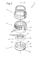
figure 2 is an exploded perspective view of the device offigure 1 ; -
figure 3 is a lateral view of the device offigure 1 ; -
figure 4 is a plan view of the device offigure 1 ; -
figure 5A is a section view of the device offigure 4 according to directrix line V-V and with some parts removed better to evidence others; -
figure 5B is a section view of the device offigure 4 according to directrix line V-V and in a complete configuration; -
figure 6 is a section view of the device offigure 4 according to directrix line VI-VI; -
figure 7 is a section view of the device offigure 4 according to directrix line VII-VII; -
figure 8 is a section view of the device offigure 4 according to directrix line VIII-VIII; -
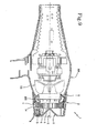
figure 9 is a section view of the device offigure 1 coupled with a hair-dryer; -
figures 10A-10C are lateral views of a silencer device according to the present invention and in accordance with further different embodiments; -
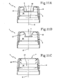
figures 11A-11C are section views, respectively, of the devices offigures 10A-10C , according to directrice lines as infigures 5A ,5B ; -
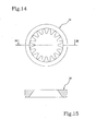
figures 12 and14 are two further embodiments of thering 14 made of sound-proofing material; -
figures 13 and15 show two sections along diameter planes respectively offigures 12 and14 ; -
figure 16 illustrates a further embodiment of thering 14 which is made by stacking of three slim rings exhibiting different internal profiling; -
figure 17 illustrates a section according to a common diameter plane of the three slim rings offigure 16 . - In accordance with the accompanying
figures, 1 denotes in its entirety a silencer device according to the present invention. - As can be seen in
figure 1 , thesilencer device 1 has a substantially cylindrical, or slightly tapered, external form, defining a sort of trunco-conical shape, closed at afirst end 1a (visible infigure 1 ) and open at theother end 1b (hidden infigure 1 as it is the lower end). - In the view of
figure 2 , thesilencer device 1 comprises acontainer structure 2, in which attenuatingmeans 3 are inserted, and asupport element 4 provided such as to block the attenuating means 3 in a stable position internally of thecontainer structure 2. - The
silencer device 1 further comprises anexternal body 5 which at least partially envelops thecontainer structure 2. Theexternal body 5 is preferably made of a rubbery material and has the function of realizing a sealed connection of thesilencer device 1 to a hair dryer (figure 9 ). - In more detail, the
container structure 2, as visible infigure 2 , exhibits alateral wall 6 having the above-mentioned tapered shape, and abottom wall 7 connected to thelateral wall 6 to close the mentionedfirst end 1a of thedevice 1. - The
whole container structure 2, and in particular thelateral wall 6, develops substantially axial-symmetrically about an axis "X" which, once thesilencer device 2 is applied to the hair-dryer 100, is parallel or coincides with the direction of the air flow in aspiration by thefan 101 of thehair dryer 100. - The
bottom wall 7 is therefore arranged transversally, preferably perpendicular, to the axis "X". - The
container structure 2 exhibits at least an inlet opening 8, an outlet opening 9 and aconduit 10 connecting the inlet opening 8 and the outlet opening 9. In the embodiment illustrated infigure 1 , thecontainer structure 2 exhibits a plurality ofinlet openings 8 distributed about the axis "X". Theopenings 8 are arranged in two diametrically-opposite groups together defining tworecesses 11 that are diametrically opposite and destined to be coupled, by interference or joint, with the rubberyexternal body 5. - The
inlet openings 8 advantageously face the axis "X" such as to define an air flow along a first transversal direction, and preferably a substantially perpendicular direction to the axis "X" itself. - In other words, the inlet openings have a transversal lie, or a substantially perpendicular lie, to the above-mentioned first direction, i.e. they are destined to enable a passage of an air flow which, when perpendicularly crossing the
inlet openings 8 themselves, is directed towards the axis "X". - In more detail, the mentioned
inlet openings 8 are made on thelateral wall 6 of thecontainer structure 2, preferably in a position that is adjacent to thebottom wall 7. - In accordance with the embodiment illustrated in
figures 1 and2 , theinlet openings 8 are elongate in the direction of the axis "X" and are preferably rectangular or substantially rectangular. Thus they are adjacent to one another along a larger side thereof. - The outlet opening 9, on the other hand, has a perpendicular lie to the axis such as to realise, in outlet from the
silencer device 1, an axial air flow along the axis "X". - The
inlet openings 8 are arranged in proximity of or at thefirst end 1a of thesilencer device 1, while the outlet opening 9 is arranged at theother end 1b of thesilencer device 1. - Further, the
silencer device 1 advantageously comprises deviatingmeans 12, active internally of theconduit 10 such as to impress, on the air flow coming from theinlet openings 8, a deviation along a second less angled direction with respect to the axis "X" of the first direction, i.e. defining an angle with the axis "X" which is smaller than the angle defined between the first direction and the axis "X". - The mentioned deviating means 12 comprise a
deviator wall 13 that is transversal to the above-mentioned first direction and which at least partly defines thebottom wall 7. - In accordance with the embodiment illustrated in
figures 5-7 and9 , thedeviator wall 13 has a conical shape with a convexity facing towards theconduit 10 and is preferably axial-symmetric with respect to the axis "X". Further, the inlet openings are advantageously directly facing thedeviator wall 13. In this way, the air flow coming from theinlet openings 8 is channelled by thedeviator wall 13 along the axis "X" towards the outlet opening 9. - As already mentioned, the sound-attenuating means 3 are housed internally of the container structure (and in particular internally of the conduit 10).
- In accordance with the present invention, the attenuating means are inserted internally of the
conduit 10 in such a position as to interfere with an air flow flowing from theinlet openings 8 towards the outlet opening 9 in such a way as to at least partly attenuate the sound vibrations of the air flow. - The lateral openings located on the circumference of the silencer, together with the central cone and the
chamber 21, force the entering air entrained by the fan to follow a compulsory pathway before being sucked in by the fan itself towards the central body of the hair dryer, without causing swirling or obstacles between the entering air and the draught air produced by the fan. The whole volume of air created is directed in its compulsory pathway towards the sound-absorbent material which attenuates the impact and significantly dampens the noise thanks also to the special configuration thereof with radial points directed towards the centre of the conduit, which offer a greater contact surface to the air passage. - The attenuating means 3 preferably comprise a
ring 14 made of a sound-absorbent material exhibiting acentral hole 15 which exhibits a plurality ofradial protrusions 16 that are reciprocally angularly equidistanced. - The
ring 14 is arranged such as to be centred on the axis "X", i.e. in such a way that thering 14 is substantially axial-symmetric with respect to the axis "X". - The
ring 14 is held in position, internally of theconduit 10, by means of the above-mentionedsupport element 4. -
Figures 12-17 illustrate various embodiments of thering 14. - The
support element 4 is substantially annular, exhibiting anannular base 17 from which aperipheral border 18 perpendicularly departs, defining, in cooperation with theannular base 17, aseating 19 having an annular shape for housing the sound-absorbent ring 14. - The
annular base 17 exhibits acentral hole 20 for passage of the axial flow of air close to reaching the outlet opening 9. - In a mounted configuration of the
support element 4, theseating 19 is thus arranged between the deviatingmeans 12 and the outlet opening 9. - The
annular base 17 and theborder 18 preferably develop circumferentially, i.e. extending along a whole angular development about the axis "X". - Advantageously, in a mounted configuration of the
support element 4, achamber 21 is preferably afforded between theborder 18 and thelateral wall 6 of thecontainer structure 2, whichchamber 21 has an annular shape and is in fluid communication with theconduit 10, the function of which is to control any swirling that might develop in theconduit 10, contributing to preventing the forming of swirlings, and to de-couple theborder 18 from thelateral wall 6 and, therefore, reduce the vibrations transmitted there-between. - Special blocking means 22 can be provided on the
container structure 2 to stably retain thering 14 internally of theannular seating 19. In the assembled configuration of thesilencer device 1, the blocking means 22 abuttingly receive corresponding portions of thering 14, thus preventing movement thereof with respect to theseating 19. - In the embodiment of
figures 5A and5B , the blocking means 22 comprise one or more axial broadenings extending from the bottom wall 7 (for example from the deviator wall 13) along the axis "X" and being of such a length as to reach the position assumed by thering 14 in the assembled configuration (figure 5B ). - The
support element 4 is stably couplable to thecontainer structure 2 by means of snap-joints, forexample tabs 28. - At the position of the
central hole 20, thesupport element 4 can exhibit acoupling flange 23 for realising a stable coupling with ahair dryer 100. Theflange 23 can comprise, for example, acylindrical portion 24 extending distancingly from theannular base 17 in an opposite direction with respect to theborder 18, and one or moreradial projections 25 extending distancingly from thecylindrical portion 24 such as to realise a connection with a corresponding attachingborder 102 of thehair dryer 100. - As previously described, the presence of the rubbery
external body 5 enables adequate fluid seal between the hair dryer 100 (and in particular the rear aspirating section thereof) and thesilencer device 1, such that the depression generated by thefan 101 of thehair dryer 100 can be transmitted up to inside theconduit 10 of thesilencer device 1. - The sealed coupling can be guaranteed by a
deformable attachment edge 27 realised at an end of the rubberyexternal body 4, destined to couple with thehair dryer 100. - With reference to the reduction effect on the emitted noise, the Applicant has found that where the axial dimension (i.e. along the axis "X") of the
inlet openings 8 is substantially equal to the axial dimension of thedeviator wall 13, the noise reduction effect is optimal. - In accordance with
figures 10A-10C illustrate lateral views of different embodiments of thesilencer device 1. Infigure 10A , theinlet openings 8 are circular and arranged on two distanced parallel lines along the axis "X". - In accordance with
figure 10B , theinlet openings 8 have an elongate shape perpendicular to the axis "X", i.e. along an angular development about the axis "X". Theinlet openings 8 are preferably two pairs, the two pairs being arranged in a diametrically opposite position with respect to the axis "X" and the twoopenings 8 of each pair being spaced along the axis "X". - In accordance with
figure 10C , theinlet openings 8 are circular and arranged on a single line about the axis "X". -
Figures 11A-11C show section views of different embodiments of thesilencer device 1. - In accordance with
figure 11A , the deviating means 12 are defined by a cylindrical wall which, in section along a plane passing through the axis "X" (as infigure 11A ), has a substantially rectangular section, possibly with bevelled or connected edges. - In accordance with
figure 11B , the deviating means 12 are defined by a concave wall that is substantially axial-symmetric about the axis "X", the concavity of the wall facing theinlet openings 8. - In accordance with
figure 11C , the deviating means 12 are defined by a pair ofdeflectors 26, extending from thelateral wall 6 of thecontainer structure 2 towards the axis "X" and inclined towards the attenuating means 3 such as to realise the mentioned deviating action of the flow entering through theinlet openings 8. - This latter configuration of the deviating means 12 is suitable for
inlet openings 8 arranged in configurations of the type illustrated infigure 10A and 10B , i.e. with two lines ofopenings 8 distanced along the axis "X". - The present invention attains the set aims.
- The special configuration of the silencer device, with the inlet openings arranged on the lateral openings and the deviating means for deviating the air coming from the lateral openings towards the axial direction and, therefore, towards the attenuating means, has been shown to be effective in reducing the noise emitted by the hair dryer. This occurs because the means set up with the introduction of the silencer: air inlet openings and their position, central cone,
chamber 21, sound-absorbent body, all prevent formation of the air swirling phenomena which can be produced on activation of the fan - between entrained air from outside towards the inside, through the filter, and air generated by the movement of the fan - and absorb the majority of the noise produced by the passage of air. - Further, the special geometry of the sound-absorbent ring, exhibiting the above-mentioned radial protrusions facing towards the axis, contribute significantly to the reduction of the sound emitted. Sound-absorbent material with a special shape/configuration - ring with internal surface, radial points - has been selected because this type of projection offers a very large sound-reducing surface to the passage of the air and, thanks also to the ring shape, offers no obstruction to air passage. The position of the sound-absorbent ring, together with the air deviator/channelling cone, is designed such that the air immediately encounters the sound-absorbent material which reduces the noise and channels it towards the inside of the hair dryer.
- The result is a greater reduction in noise with respect to devices of the prior art, which exploit an axial aspiration through openings realised on the bottom wall. This improvement, among other things, is obtained without a corresponding increase in power absorbed and, indeed, the special structure of the silencer device of the invention leads to less power wastage with respect to traditional systems.
- This produces a benefit in terms of acoustic comfort in use, as well as an applicability to hair dryers of professional type where the absorbance of power on the part of the silencer device does not have a negative effect on the performance of the hair dryer.
Claims (11)
- A silencer device for a hair dryer, comprising:a container structure (2) developing about an axis (X) and exhibiting at least an inlet opening (8), and an outlet opening (9) and a conduit (10) connecting the inlet (8) and outlet (9) openings to one another;attenuating means (3), inserted internally of the conduit (10) for interfering with a flow of air between the inlet opening (8) and the outlet (9) opening in such a way as to at least partly attenuate sound vibrations associated to the air flow;characterised in that the at least an inlet opening (8) faces the axis (X) in order to define an air flow along a transversal direction, and preferably substantially perpendicular, to the axis (X), and in that the silencer device (1) further comprises deviating means (12),acting internally of the conduit (10) such as to impress on the air flow coming from the inlet opening (8) an axial deviation along the axis (X).
- The device of claim 1, wherein the container structure (2) comprises a lateral wall (6), developing about the axis (X), and a bottom wall (7) arranged transversally of the axis (X) and connected to the lateral wall (6), and wherein the at least an inlet opening (8) is realised on the lateral wall (6), preferably in an adjacent position to the bottom wall (7).
- The device of claim 1 or 2, wherein the deviating means (12) at least partially define the bottom wall (7).
- The device of any one of the preceding claims, wherein the deviating means (12) comprise a deviator wall (13) which is transversal to the first air flow direction coming from the inlet opening (8), the at least an inlet opening (8) directly facing the deviator wall (13).
- The device of claim 4, wherein the deviator wall (13) extends about the axis (X), preferably over a whole angular development thereof, and wherein the containing structure (2) exhibits a plurality of inlet openings (8) distributed about the axis (X) and directly facing the deviator wall (13).
- The device of claim 5, wherein the deviator wall (13) has a conical shape having a convexity facing towards the conduit (10) and is preferably axial symmetric about the axis (X).
- The device of any one of the preceding claims, wherein the outlet opening (9) has a transversal and preferably perpendicular lie in relation to the axis (X), in order to realise a flow of axial air along the axis (X) in outlet from the silencer device (1).
- The device of any one of the preceding claims, further comprising a support element (4) which is stably couplable to the container structure (2) at the outlet opening (9) and which exhibits a seating (19) for containing the attenuating means (3).
- The device of any one of the preceding claims, wherein the attenuating means (3) comprise a ring (14) made of a sound-absorbent material which exhibits a central hole (15) a profile of which ring (14) exhibits a plurality of radial protrusions (16) which are angularly arranged to one another.
- The device of claim 9, when it depends on claim 2, wherein a chamber (22) is afforded between the ring (14) made of a sound-absorbent material and the lateral wall (6) of the container structure (2), which chamber (22) is placed in fluid communication with the conduit (10) for controlling possible air swirls and/or possible vibrations transmitted from the ring (14) to the lateral surface (6).
- The device of claim 8 or 9, further comprising an external body (5), preferably rubbery, having an attaching edge (27) which is deformable such as to enable a sealed coupling with a hair-dryer (100), the container structure (2) being stably connectable to the external rubbery body (4), preferably by means of reciprocal insertion.
Applications Claiming Priority (1)
| Application Number | Priority Date | Filing Date | Title |
|---|---|---|---|
| ITMO2010A000221A IT1401326B1 (en) | 2010-07-29 | 2010-07-29 | SILENCER DEVICE FOR HAIRDRYER. |
Publications (2)
| Publication Number | Publication Date |
|---|---|
| EP2412272A1 true EP2412272A1 (en) | 2012-02-01 |
| EP2412272B1 EP2412272B1 (en) | 2013-06-19 |
Family
ID=43739956
Family Applications (1)
| Application Number | Title | Priority Date | Filing Date |
|---|---|---|---|
| EP11003443.6A Active EP2412272B1 (en) | 2010-07-29 | 2011-04-27 | A silencer device for a hair dryer |
Country Status (5)
| Country | Link |
|---|---|
| US (1) | US8307948B2 (en) |
| EP (1) | EP2412272B1 (en) |
| BR (1) | BRPI1103466B1 (en) |
| IT (1) | IT1401326B1 (en) |
| RU (1) | RU2011121421A (en) |
Cited By (4)
| Publication number | Priority date | Publication date | Assignee | Title |
|---|---|---|---|---|
| GB2497192A (en) * | 2011-11-29 | 2013-06-05 | Jui-Hung Yang | Hair dryer with noise reduction means |
| EP2989925A1 (en) * | 2014-08-27 | 2016-03-02 | BSH Hausgeräte GmbH | Hair dryer |
| EP3071066A4 (en) * | 2014-01-23 | 2016-11-02 | Conair | HAIRDRYING APPARATUS HAVING A NOISE REDUCTION TOOL |
| WO2017072112A1 (en) | 2015-10-27 | 2017-05-04 | Babyliss Faco Sprl | Hair dryer with improved acoustic performance |
Families Citing this family (25)
| Publication number | Priority date | Publication date | Assignee | Title |
|---|---|---|---|---|
| US9273077B2 (en) | 2008-05-21 | 2016-03-01 | Ariad Pharmaceuticals, Inc. | Phosphorus derivatives as kinase inhibitors |
| USD671261S1 (en) * | 2011-03-10 | 2012-11-20 | Parlux Spa | Silencer for hand -held electric hair dryer |
| US9834518B2 (en) | 2011-05-04 | 2017-12-05 | Ariad Pharmaceuticals, Inc. | Compounds for inhibiting cell proliferation in EGFR-driven cancers |
| US10739932B2 (en) * | 2011-10-11 | 2020-08-11 | Semi-Linear, Inc. | Systems and methods for interactive mobile electronic content creation and publication |
| US8939253B1 (en) * | 2012-04-27 | 2015-01-27 | The United States Of America As Represented By The Administrator Of The National Aeronautics And Space Administration | System and method for suppression of unwanted noise in ground test facilities |
| US20150166591A1 (en) | 2012-05-05 | 2015-06-18 | Ariad Pharmaceuticals, Inc. | Methods and compositions for raf kinase mediated diseases |
| US10046894B1 (en) * | 2012-05-24 | 2018-08-14 | Milton Carter | Variable speed heat air gun and cooperating kit |
| JP6051022B2 (en) * | 2012-11-12 | 2016-12-21 | シャープ株式会社 | Blower |
| US9611283B1 (en) | 2013-04-10 | 2017-04-04 | Ariad Pharmaceuticals, Inc. | Methods for inhibiting cell proliferation in ALK-driven cancers |
| USD729449S1 (en) * | 2013-07-19 | 2015-05-12 | Jemella Group Limited | Grille |
| USD726960S1 (en) | 2013-12-02 | 2015-04-14 | Conair Corporation | Noise reducing filter end cap for a hair dryer |
| USD726959S1 (en) | 2013-12-02 | 2015-04-14 | Conair Corporation | Noise reducing filter end cap for a hair dryer |
| USD726958S1 (en) | 2013-12-02 | 2015-04-14 | Conair Corporation | Hair dryer |
| EP3157773B1 (en) * | 2014-06-20 | 2020-02-12 | Poli-Model S.r.l. | Air-heating blower device for a motor vehicle |
| US10430120B2 (en) * | 2014-07-30 | 2019-10-01 | Industrial Technology Research Institute | Data object management method and data object management system |
| JP2016135229A (en) * | 2015-01-23 | 2016-07-28 | 日本電産株式会社 | Hair dryer |
| FR3039376B1 (en) * | 2015-07-28 | 2017-09-01 | Seb Sa | HAIRDRYER WITH OPTIMIZED AIR INTAKE CANALIZATION |
| FR3039375B1 (en) * | 2015-07-28 | 2017-09-01 | Seb Sa | HAIRDRYER WITH AIR INTAKE PIPING WITH OPTIMIZED ACOUSTIC PERFORMANCE |
| TWI638620B (en) * | 2016-12-30 | 2018-10-21 | 佛山市建準電子有限公司 | Blower and noise-absorbing device thereof |
| US11035384B2 (en) * | 2018-04-25 | 2021-06-15 | Sonny's Enterprises, Llc | Silencer for an air blower assembly and air blower assembly having the silencer |
| WO2019207684A1 (en) * | 2018-04-25 | 2019-10-31 | 三菱電機株式会社 | Electrical device casing, refrigeration cycle device, and electrical device |
| KR102532472B1 (en) * | 2018-09-19 | 2023-05-12 | 엘지전자 주식회사 | Dryer |
| JP1649524S (en) * | 2018-10-04 | 2020-01-14 | ||
| WO2021237316A1 (en) * | 2020-05-28 | 2021-12-02 | Jobem Donada | Hairdryer provided with a noise silencing system and a sound system |
| USD1056335S1 (en) * | 2023-05-10 | 2024-12-31 | Shenzhen Cuco Smart Technology Co., Ltd | Accessory for hair dryers |
Citations (4)
| Publication number | Priority date | Publication date | Assignee | Title |
|---|---|---|---|---|
| US4025223A (en) * | 1974-12-04 | 1977-05-24 | Braun Aktiengesellschaft | Fan arrangement |
| DE8805910U1 (en) * | 1988-05-04 | 1988-06-16 | Merges, Marco, 5000 Köln | Device for dampening the noise of a hair dryer |
| US20090188126A1 (en) * | 2008-01-25 | 2009-07-30 | Christophe Gaillard | Silencer for Drying Appliance and Silent Hair Dryer |
| WO2010045698A1 (en) * | 2008-10-23 | 2010-04-29 | Rodrigues Oscar Jose | Electrical hair dryer with noise reducer and noise reducer |
Family Cites Families (25)
| Publication number | Priority date | Publication date | Assignee | Title |
|---|---|---|---|---|
| US3383700A (en) * | 1965-11-26 | 1968-05-14 | Ronson Corp | Portable hair dryer |
| US3397463A (en) * | 1966-01-03 | 1968-08-20 | Laing Nikolaus | Hair dryers |
| US3818600A (en) * | 1973-04-23 | 1974-06-25 | Gillette Co | Hair dryer with hood |
| US4596921A (en) * | 1984-05-22 | 1986-06-24 | Hersh Alan S | Low noise hand-held hairdryer |
| DE3428650C2 (en) * | 1984-08-03 | 1986-08-14 | Braun Ag, 6000 Frankfurt | Hair dryer with axial fan |
| US4658511A (en) * | 1984-09-19 | 1987-04-21 | Robert Krups Stiftung & Co. Kg | Electric hair dryer with air dispersing hood |
| DE4204893A1 (en) * | 1992-02-19 | 1993-08-26 | Rbi Distributors Inc | INLET FILTER FOR HAIR FROEN |
| US5490336A (en) * | 1994-01-10 | 1996-02-13 | Smick; Gary L. | Air intake filter for electric appliances |
| US5467540A (en) * | 1994-07-11 | 1995-11-21 | Bastien; Ernest J. | Diffuser for hair dryer |
| DE19635933B4 (en) * | 1996-09-05 | 2007-11-29 | Braun Gmbh | Hair care device |
| US5841943A (en) * | 1997-04-25 | 1998-11-24 | Soundesign, Llc | Ducted flow hair dryer with multiple impellers |
| US5875562A (en) * | 1997-06-18 | 1999-03-02 | Fogarty; Shaun P. | Hand-held hair dryer with vibration and noise control |
| US6148537A (en) * | 1998-10-16 | 2000-11-21 | Wahl Clipper Corporation | Hair drying device with reduced sound emissions |
| US6212790B1 (en) * | 1999-04-15 | 2001-04-10 | Delia Stetson | Protective cover for hairdryer |
| EP1103202A1 (en) * | 1999-06-08 | 2001-05-30 | Sanyo Electric Co., Ltd. | Hair dryer |
| US6393208B1 (en) * | 2000-08-14 | 2002-05-21 | Daniel M. Nosenchuck | Compressor with integrated impeller and motor |
| DE20019861U1 (en) * | 2000-11-23 | 2001-03-08 | Wu, Hsiu-Mei, Yang Mei, Taoyuan | Hair dryer |
| US20030079366A1 (en) * | 2001-10-25 | 2003-05-01 | Chun-Chuan Chang | Hair dryer |
| DE10160465C2 (en) * | 2001-12-10 | 2003-10-02 | Elaplast Technik Gmbh | Electrical device with silencer |
| KR100424580B1 (en) * | 2001-12-20 | 2004-03-27 | 엘지전자 주식회사 | Device for locking ventilation cover to main body |
| KR100424581B1 (en) * | 2001-12-20 | 2004-03-27 | 엘지전자 주식회사 | Device for locking ventilation filter for vacuum cleaner |
| US20060254073A1 (en) * | 2005-05-11 | 2006-11-16 | Zhen Tim T | Dual-fan hairdrying apparatus |
| US20070294909A1 (en) * | 2006-06-26 | 2007-12-27 | Abdi Frank F | Noiseless hair dryer |
| US20110010958A1 (en) * | 2009-07-16 | 2011-01-20 | Wayne Clark | Quiet hair dryer |
| EP2327327A1 (en) * | 2009-11-26 | 2011-06-01 | Babyliss Faco S.A. | Add-on silencer for hairdryer |
-
2010
- 2010-07-29 IT ITMO2010A000221A patent/IT1401326B1/en active
-
2011
- 2011-04-27 EP EP11003443.6A patent/EP2412272B1/en active Active
- 2011-05-30 RU RU2011121421/12A patent/RU2011121421A/en not_active Application Discontinuation
- 2011-06-20 US US13/164,360 patent/US8307948B2/en not_active Expired - Fee Related
- 2011-07-26 BR BRPI1103466A patent/BRPI1103466B1/en not_active IP Right Cessation
Patent Citations (4)
| Publication number | Priority date | Publication date | Assignee | Title |
|---|---|---|---|---|
| US4025223A (en) * | 1974-12-04 | 1977-05-24 | Braun Aktiengesellschaft | Fan arrangement |
| DE8805910U1 (en) * | 1988-05-04 | 1988-06-16 | Merges, Marco, 5000 Köln | Device for dampening the noise of a hair dryer |
| US20090188126A1 (en) * | 2008-01-25 | 2009-07-30 | Christophe Gaillard | Silencer for Drying Appliance and Silent Hair Dryer |
| WO2010045698A1 (en) * | 2008-10-23 | 2010-04-29 | Rodrigues Oscar Jose | Electrical hair dryer with noise reducer and noise reducer |
Cited By (4)
| Publication number | Priority date | Publication date | Assignee | Title |
|---|---|---|---|---|
| GB2497192A (en) * | 2011-11-29 | 2013-06-05 | Jui-Hung Yang | Hair dryer with noise reduction means |
| EP3071066A4 (en) * | 2014-01-23 | 2016-11-02 | Conair | HAIRDRYING APPARATUS HAVING A NOISE REDUCTION TOOL |
| EP2989925A1 (en) * | 2014-08-27 | 2016-03-02 | BSH Hausgeräte GmbH | Hair dryer |
| WO2017072112A1 (en) | 2015-10-27 | 2017-05-04 | Babyliss Faco Sprl | Hair dryer with improved acoustic performance |
Also Published As
| Publication number | Publication date |
|---|---|
| BRPI1103466B1 (en) | 2020-04-14 |
| IT1401326B1 (en) | 2013-07-18 |
| EP2412272B1 (en) | 2013-06-19 |
| BRPI1103466A2 (en) | 2015-08-18 |
| US8307948B2 (en) | 2012-11-13 |
| ITMO20100221A1 (en) | 2012-01-30 |
| RU2011121421A (en) | 2012-12-10 |
| US20120024620A1 (en) | 2012-02-02 |
Similar Documents
| Publication | Publication Date | Title |
|---|---|---|
| EP2412272B1 (en) | A silencer device for a hair dryer | |
| KR102508810B1 (en) | wearable air purifier | |
| KR102539567B1 (en) | wearable air purifier | |
| US7357337B2 (en) | Flow regulator | |
| JP7198354B2 (en) | air treatment equipment | |
| CN103711984B (en) | Simplified modal attenuator | |
| US4673058A (en) | High performance automotive muffler | |
| JP6991344B2 (en) | Noise dampers for compressed air systems, and methods for manufacturing noise dampers | |
| CA1092985A (en) | Muffler assembly | |
| US9291282B2 (en) | Swept outlet noise reducing element | |
| RU2765129C2 (en) | Ball valve with modal noise muffler | |
| US11680731B2 (en) | Sound reduction grille assembly | |
| US20130183141A1 (en) | Air moving devices | |
| CA2828090A1 (en) | Improved noise control via outlet jet frequency dispersal | |
| KR102117809B1 (en) | Noise attenuation unit for engine systems | |
| US6035485A (en) | Vacuum cleaner muffler/deflector | |
| KR102391133B1 (en) | Damping valve for a vibration damper | |
| ITTO20000932A1 (en) | EXHAUST SILENCER, IN PARTICULAR FOR A COMPRESSOR GROUP. | |
| KR101953213B1 (en) | Silencer | |
| TW201632320A (en) | Pneumatic tool with muffling structure | |
| US12523394B2 (en) | Sound reduction ventilation assembly | |
| JPH0229206Y2 (en) | ||
| US6296074B1 (en) | Noise reducing exhaust system and method | |
| US20260104179A1 (en) | Sound reduction fan inlet | |
| ES2973517T3 (en) | A duct to evacuate smoke from environments, particularly to evacuate cooking fumes and domestic hood that has such a duct. |
Legal Events
| Date | Code | Title | Description |
|---|---|---|---|
| 17P | Request for examination filed |
Effective date: 20111214 |
|
| AK | Designated contracting states |
Kind code of ref document: A1 Designated state(s): AL AT BE BG CH CY CZ DE DK EE ES FI FR GB GR HR HU IE IS IT LI LT LU LV MC MK MT NL NO PL PT RO RS SE SI SK SM TR |
|
| AX | Request for extension of the european patent |
Extension state: BA ME |
|
| PUAI | Public reference made under article 153(3) epc to a published international application that has entered the european phase |
Free format text: ORIGINAL CODE: 0009012 |
|
| 17Q | First examination report despatched |
Effective date: 20120127 |
|
| GRAP | Despatch of communication of intention to grant a patent |
Free format text: ORIGINAL CODE: EPIDOSNIGR1 |
|
| GRAS | Grant fee paid |
Free format text: ORIGINAL CODE: EPIDOSNIGR3 |
|
| INTG | Intention to grant announced |
Effective date: 20130418 |
|
| RIN1 | Information on inventor provided before grant (corrected) |
Inventor name: PARODI, PAOLO |
|
| GRAA | (expected) grant |
Free format text: ORIGINAL CODE: 0009210 |
|
| AK | Designated contracting states |
Kind code of ref document: B1 Designated state(s): AL AT BE BG CH CY CZ DE DK EE ES FI FR GB GR HR HU IE IS IT LI LT LU LV MC MK MT NL NO PL PT RO RS SE SI SK SM TR |
|
| AX | Request for extension of the european patent |
Extension state: BA ME |
|
| REG | Reference to a national code |
Ref country code: GB Ref legal event code: FG4D |
|
| REG | Reference to a national code |
Ref country code: CH Ref legal event code: EP |
|
| REG | Reference to a national code |
Ref country code: AT Ref legal event code: REF Ref document number: 617161 Country of ref document: AT Kind code of ref document: T Effective date: 20130715 |
|
| REG | Reference to a national code |
Ref country code: IE Ref legal event code: FG4D |
|
| REG | Reference to a national code |
Ref country code: DE Ref legal event code: R096 Ref document number: 602011002025 Country of ref document: DE Effective date: 20130814 |
|
| PG25 | Lapsed in a contracting state [announced via postgrant information from national office to epo] |
Ref country code: FI Free format text: LAPSE BECAUSE OF FAILURE TO SUBMIT A TRANSLATION OF THE DESCRIPTION OR TO PAY THE FEE WITHIN THE PRESCRIBED TIME-LIMIT Effective date: 20130619 Ref country code: GR Free format text: LAPSE BECAUSE OF FAILURE TO SUBMIT A TRANSLATION OF THE DESCRIPTION OR TO PAY THE FEE WITHIN THE PRESCRIBED TIME-LIMIT Effective date: 20130920 Ref country code: SI Free format text: LAPSE BECAUSE OF FAILURE TO SUBMIT A TRANSLATION OF THE DESCRIPTION OR TO PAY THE FEE WITHIN THE PRESCRIBED TIME-LIMIT Effective date: 20130619 Ref country code: LT Free format text: LAPSE BECAUSE OF FAILURE TO SUBMIT A TRANSLATION OF THE DESCRIPTION OR TO PAY THE FEE WITHIN THE PRESCRIBED TIME-LIMIT Effective date: 20130619 Ref country code: ES Free format text: LAPSE BECAUSE OF FAILURE TO SUBMIT A TRANSLATION OF THE DESCRIPTION OR TO PAY THE FEE WITHIN THE PRESCRIBED TIME-LIMIT Effective date: 20130930 Ref country code: SE Free format text: LAPSE BECAUSE OF FAILURE TO SUBMIT A TRANSLATION OF THE DESCRIPTION OR TO PAY THE FEE WITHIN THE PRESCRIBED TIME-LIMIT Effective date: 20130619 Ref country code: NO Free format text: LAPSE BECAUSE OF FAILURE TO SUBMIT A TRANSLATION OF THE DESCRIPTION OR TO PAY THE FEE WITHIN THE PRESCRIBED TIME-LIMIT Effective date: 20130919 |
|
| REG | Reference to a national code |
Ref country code: AT Ref legal event code: MK05 Ref document number: 617161 Country of ref document: AT Kind code of ref document: T Effective date: 20130619 |
|
| REG | Reference to a national code |
Ref country code: LT Ref legal event code: MG4D |
|
| PG25 | Lapsed in a contracting state [announced via postgrant information from national office to epo] |
Ref country code: HR Free format text: LAPSE BECAUSE OF FAILURE TO SUBMIT A TRANSLATION OF THE DESCRIPTION OR TO PAY THE FEE WITHIN THE PRESCRIBED TIME-LIMIT Effective date: 20130619 Ref country code: BG Free format text: LAPSE BECAUSE OF FAILURE TO SUBMIT A TRANSLATION OF THE DESCRIPTION OR TO PAY THE FEE WITHIN THE PRESCRIBED TIME-LIMIT Effective date: 20130919 Ref country code: RS Free format text: LAPSE BECAUSE OF FAILURE TO SUBMIT A TRANSLATION OF THE DESCRIPTION OR TO PAY THE FEE WITHIN THE PRESCRIBED TIME-LIMIT Effective date: 20130619 |
|
| REG | Reference to a national code |
Ref country code: NL Ref legal event code: VDEP Effective date: 20130619 |
|
| PG25 | Lapsed in a contracting state [announced via postgrant information from national office to epo] |
Ref country code: LV Free format text: LAPSE BECAUSE OF FAILURE TO SUBMIT A TRANSLATION OF THE DESCRIPTION OR TO PAY THE FEE WITHIN THE PRESCRIBED TIME-LIMIT Effective date: 20130619 |
|
| PG25 | Lapsed in a contracting state [announced via postgrant information from national office to epo] |
Ref country code: EE Free format text: LAPSE BECAUSE OF FAILURE TO SUBMIT A TRANSLATION OF THE DESCRIPTION OR TO PAY THE FEE WITHIN THE PRESCRIBED TIME-LIMIT Effective date: 20130619 Ref country code: PT Free format text: LAPSE BECAUSE OF FAILURE TO SUBMIT A TRANSLATION OF THE DESCRIPTION OR TO PAY THE FEE WITHIN THE PRESCRIBED TIME-LIMIT Effective date: 20131021 Ref country code: IS Free format text: LAPSE BECAUSE OF FAILURE TO SUBMIT A TRANSLATION OF THE DESCRIPTION OR TO PAY THE FEE WITHIN THE PRESCRIBED TIME-LIMIT Effective date: 20131019 Ref country code: CY Free format text: LAPSE BECAUSE OF FAILURE TO SUBMIT A TRANSLATION OF THE DESCRIPTION OR TO PAY THE FEE WITHIN THE PRESCRIBED TIME-LIMIT Effective date: 20130807 Ref country code: BE Free format text: LAPSE BECAUSE OF FAILURE TO SUBMIT A TRANSLATION OF THE DESCRIPTION OR TO PAY THE FEE WITHIN THE PRESCRIBED TIME-LIMIT Effective date: 20130619 Ref country code: AT Free format text: LAPSE BECAUSE OF FAILURE TO SUBMIT A TRANSLATION OF THE DESCRIPTION OR TO PAY THE FEE WITHIN THE PRESCRIBED TIME-LIMIT Effective date: 20130619 Ref country code: SK Free format text: LAPSE BECAUSE OF FAILURE TO SUBMIT A TRANSLATION OF THE DESCRIPTION OR TO PAY THE FEE WITHIN THE PRESCRIBED TIME-LIMIT Effective date: 20130619 Ref country code: CZ Free format text: LAPSE BECAUSE OF FAILURE TO SUBMIT A TRANSLATION OF THE DESCRIPTION OR TO PAY THE FEE WITHIN THE PRESCRIBED TIME-LIMIT Effective date: 20130619 |
|
| PG25 | Lapsed in a contracting state [announced via postgrant information from national office to epo] |
Ref country code: PL Free format text: LAPSE BECAUSE OF FAILURE TO SUBMIT A TRANSLATION OF THE DESCRIPTION OR TO PAY THE FEE WITHIN THE PRESCRIBED TIME-LIMIT Effective date: 20130619 Ref country code: NL Free format text: LAPSE BECAUSE OF FAILURE TO SUBMIT A TRANSLATION OF THE DESCRIPTION OR TO PAY THE FEE WITHIN THE PRESCRIBED TIME-LIMIT Effective date: 20130619 Ref country code: RO Free format text: LAPSE BECAUSE OF FAILURE TO SUBMIT A TRANSLATION OF THE DESCRIPTION OR TO PAY THE FEE WITHIN THE PRESCRIBED TIME-LIMIT Effective date: 20130619 |
|
| PLBI | Opposition filed |
Free format text: ORIGINAL CODE: 0009260 |
|
| PG25 | Lapsed in a contracting state [announced via postgrant information from national office to epo] |
Ref country code: CY Free format text: LAPSE BECAUSE OF FAILURE TO SUBMIT A TRANSLATION OF THE DESCRIPTION OR TO PAY THE FEE WITHIN THE PRESCRIBED TIME-LIMIT Effective date: 20130619 |
|
| 26 | Opposition filed |
Opponent name: UKI INTERNATIONAL S.R.L. Effective date: 20140318 |
|
| PLAX | Notice of opposition and request to file observation + time limit sent |
Free format text: ORIGINAL CODE: EPIDOSNOBS2 |
|
| PG25 | Lapsed in a contracting state [announced via postgrant information from national office to epo] |
Ref country code: DK Free format text: LAPSE BECAUSE OF FAILURE TO SUBMIT A TRANSLATION OF THE DESCRIPTION OR TO PAY THE FEE WITHIN THE PRESCRIBED TIME-LIMIT Effective date: 20130619 |
|
| PLBP | Opposition withdrawn |
Free format text: ORIGINAL CODE: 0009264 |
|
| REG | Reference to a national code |
Ref country code: DE Ref legal event code: R026 Ref document number: 602011002025 Country of ref document: DE Effective date: 20140318 |
|
| PLBB | Reply of patent proprietor to notice(s) of opposition received |
Free format text: ORIGINAL CODE: EPIDOSNOBS3 |
|
| PLBD | Termination of opposition procedure: decision despatched |
Free format text: ORIGINAL CODE: EPIDOSNOPC1 |
|
| REG | Reference to a national code |
Ref country code: DE Ref legal event code: R100 Ref document number: 602011002025 Country of ref document: DE |
|
| REG | Reference to a national code |
Ref country code: DE Ref legal event code: R119 Ref document number: 602011002025 Country of ref document: DE |
|
| PG25 | Lapsed in a contracting state [announced via postgrant information from national office to epo] |
Ref country code: LU Free format text: LAPSE BECAUSE OF FAILURE TO SUBMIT A TRANSLATION OF THE DESCRIPTION OR TO PAY THE FEE WITHIN THE PRESCRIBED TIME-LIMIT Effective date: 20140427 Ref country code: MC Free format text: LAPSE BECAUSE OF FAILURE TO SUBMIT A TRANSLATION OF THE DESCRIPTION OR TO PAY THE FEE WITHIN THE PRESCRIBED TIME-LIMIT Effective date: 20130619 |
|
| REG | Reference to a national code |
Ref country code: CH Ref legal event code: PL |
|
| REG | Reference to a national code |
Ref country code: IE Ref legal event code: MM4A |
|
| PG25 | Lapsed in a contracting state [announced via postgrant information from national office to epo] |
Ref country code: CH Free format text: LAPSE BECAUSE OF NON-PAYMENT OF DUE FEES Effective date: 20140430 Ref country code: DE Free format text: LAPSE BECAUSE OF NON-PAYMENT OF DUE FEES Effective date: 20141101 Ref country code: LI Free format text: LAPSE BECAUSE OF NON-PAYMENT OF DUE FEES Effective date: 20140430 |
|
| PLBM | Termination of opposition procedure: date of legal effect published |
Free format text: ORIGINAL CODE: 0009276 |
|
| STAA | Information on the status of an ep patent application or granted ep patent |
Free format text: STATUS: OPPOSITION PROCEDURE CLOSED |
|
| REG | Reference to a national code |
Ref country code: DE Ref legal event code: R119 Ref document number: 602011002025 Country of ref document: DE Effective date: 20141101 |
|
| 27C | Opposition proceedings terminated |
Effective date: 20141023 |
|
| PG25 | Lapsed in a contracting state [announced via postgrant information from national office to epo] |
Ref country code: IE Free format text: LAPSE BECAUSE OF NON-PAYMENT OF DUE FEES Effective date: 20140427 |
|
| GBPC | Gb: european patent ceased through non-payment of renewal fee |
Effective date: 20150427 |
|
| PG25 | Lapsed in a contracting state [announced via postgrant information from national office to epo] |
Ref country code: GB Free format text: LAPSE BECAUSE OF NON-PAYMENT OF DUE FEES Effective date: 20150427 |
|
| PG25 | Lapsed in a contracting state [announced via postgrant information from national office to epo] |
Ref country code: MT Free format text: LAPSE BECAUSE OF FAILURE TO SUBMIT A TRANSLATION OF THE DESCRIPTION OR TO PAY THE FEE WITHIN THE PRESCRIBED TIME-LIMIT Effective date: 20130619 |
|
| REG | Reference to a national code |
Ref country code: FR Ref legal event code: PLFP Year of fee payment: 6 |
|
| PG25 | Lapsed in a contracting state [announced via postgrant information from national office to epo] |
Ref country code: IT Free format text: LAPSE BECAUSE OF NON-PAYMENT OF DUE FEES Effective date: 20150427 Ref country code: SM Free format text: LAPSE BECAUSE OF FAILURE TO SUBMIT A TRANSLATION OF THE DESCRIPTION OR TO PAY THE FEE WITHIN THE PRESCRIBED TIME-LIMIT Effective date: 20130619 |
|
| PG25 | Lapsed in a contracting state [announced via postgrant information from national office to epo] |
Ref country code: HU Free format text: LAPSE BECAUSE OF FAILURE TO SUBMIT A TRANSLATION OF THE DESCRIPTION OR TO PAY THE FEE WITHIN THE PRESCRIBED TIME-LIMIT; INVALID AB INITIO Effective date: 20110427 Ref country code: TR Free format text: LAPSE BECAUSE OF FAILURE TO SUBMIT A TRANSLATION OF THE DESCRIPTION OR TO PAY THE FEE WITHIN THE PRESCRIBED TIME-LIMIT Effective date: 20130619 |
|
| PGRI | Patent reinstated in contracting state [announced from national office to epo] |
Ref country code: IT Effective date: 20161122 |
|
| REG | Reference to a national code |
Ref country code: FR Ref legal event code: PLFP Year of fee payment: 7 |
|
| REG | Reference to a national code |
Ref country code: FR Ref legal event code: PLFP Year of fee payment: 8 |
|
| PG25 | Lapsed in a contracting state [announced via postgrant information from national office to epo] |
Ref country code: MK Free format text: LAPSE BECAUSE OF FAILURE TO SUBMIT A TRANSLATION OF THE DESCRIPTION OR TO PAY THE FEE WITHIN THE PRESCRIBED TIME-LIMIT Effective date: 20130619 |
|
| PG25 | Lapsed in a contracting state [announced via postgrant information from national office to epo] |
Ref country code: AL Free format text: LAPSE BECAUSE OF FAILURE TO SUBMIT A TRANSLATION OF THE DESCRIPTION OR TO PAY THE FEE WITHIN THE PRESCRIBED TIME-LIMIT Effective date: 20130619 |
|
| PGFP | Annual fee paid to national office [announced via postgrant information from national office to epo] |
Ref country code: IT Payment date: 20240424 Year of fee payment: 14 Ref country code: FR Payment date: 20240430 Year of fee payment: 14 |
|
| PG25 | Lapsed in a contracting state [announced via postgrant information from national office to epo] |
Ref country code: FR Free format text: LAPSE BECAUSE OF NON-PAYMENT OF DUE FEES Effective date: 20250430 |