EP2412557A1 - Vehicluar display system, method of displaying and vehicle - Google Patents
Vehicluar display system, method of displaying and vehicle Download PDFInfo
- Publication number
- EP2412557A1 EP2412557A1 EP10755742A EP10755742A EP2412557A1 EP 2412557 A1 EP2412557 A1 EP 2412557A1 EP 10755742 A EP10755742 A EP 10755742A EP 10755742 A EP10755742 A EP 10755742A EP 2412557 A1 EP2412557 A1 EP 2412557A1
- Authority
- EP
- European Patent Office
- Prior art keywords
- vehicle
- view image
- display object
- preceding vehicle
- self
- Prior art date
- Legal status (The legal status is an assumption and is not a legal conclusion. Google has not performed a legal analysis and makes no representation as to the accuracy of the status listed.)
- Withdrawn
Links
Images







Classifications
-
- G—PHYSICS
- G02—OPTICS
- G02B—OPTICAL ELEMENTS, SYSTEMS OR APPARATUS
- G02B27/00—Optical systems or apparatus not provided for by any of the groups G02B1/00 - G02B26/00, G02B30/00
- G02B27/01—Head-up displays
-
- G—PHYSICS
- G01—MEASURING; TESTING
- G01C—MEASURING DISTANCES, LEVELS OR BEARINGS; SURVEYING; NAVIGATION; GYROSCOPIC INSTRUMENTS; PHOTOGRAMMETRY OR VIDEOGRAMMETRY
- G01C21/00—Navigation; Navigational instruments not provided for in groups G01C1/00 - G01C19/00
- G01C21/26—Navigation; Navigational instruments not provided for in groups G01C1/00 - G01C19/00 specially adapted for navigation in a road network
- G01C21/34—Route searching; Route guidance
- G01C21/36—Input/output arrangements for on-board computers
- G01C21/3626—Details of the output of route guidance instructions
- G01C21/365—Guidance using head up displays or projectors, e.g. virtual vehicles or arrows projected on the windscreen or on the road itself
-
- G—PHYSICS
- G06—COMPUTING OR CALCULATING; COUNTING
- G06F—ELECTRIC DIGITAL DATA PROCESSING
- G06F3/00—Input arrangements for transferring data to be processed into a form capable of being handled by the computer; Output arrangements for transferring data from processing unit to output unit, e.g. interface arrangements
- G06F3/01—Input arrangements or combined input and output arrangements for interaction between user and computer
- G06F3/011—Arrangements for interaction with the human body, e.g. for user immersion in virtual reality
- G06F3/013—Eye tracking input arrangements
-
- G—PHYSICS
- G08—SIGNALLING
- G08G—TRAFFIC CONTROL SYSTEMS
- G08G1/00—Traffic control systems for road vehicles
- G08G1/09—Arrangements for giving variable traffic instructions
- G08G1/0962—Arrangements for giving variable traffic instructions having an indicator mounted inside the vehicle, e.g. giving voice messages
- G08G1/09626—Arrangements for giving variable traffic instructions having an indicator mounted inside the vehicle, e.g. giving voice messages where the origin of the information is within the own vehicle, e.g. a local storage device, digital map
-
- G—PHYSICS
- G08—SIGNALLING
- G08G—TRAFFIC CONTROL SYSTEMS
- G08G1/00—Traffic control systems for road vehicles
- G08G1/16—Anti-collision systems
- G08G1/166—Anti-collision systems for active traffic, e.g. moving vehicles, pedestrians, bikes
-
- B—PERFORMING OPERATIONS; TRANSPORTING
- B60—VEHICLES IN GENERAL
- B60R—VEHICLES, VEHICLE FITTINGS, OR VEHICLE PARTS, NOT OTHERWISE PROVIDED FOR
- B60R2300/00—Details of viewing arrangements using cameras and displays, specially adapted for use in a vehicle
- B60R2300/20—Details of viewing arrangements using cameras and displays, specially adapted for use in a vehicle characterised by the type of display used
- B60R2300/205—Details of viewing arrangements using cameras and displays, specially adapted for use in a vehicle characterised by the type of display used using a head-up display
-
- G—PHYSICS
- G02—OPTICS
- G02B—OPTICAL ELEMENTS, SYSTEMS OR APPARATUS
- G02B27/00—Optical systems or apparatus not provided for by any of the groups G02B1/00 - G02B26/00, G02B30/00
- G02B27/01—Head-up displays
- G02B27/0101—Head-up displays characterised by optical features
- G02B2027/0118—Head-up displays characterised by optical features comprising devices for improving the contrast of the display / brillance control visibility
- G02B2027/012—Head-up displays characterised by optical features comprising devices for improving the contrast of the display / brillance control visibility comprising devices for attenuating parasitic image effects
-
- G—PHYSICS
- G02—OPTICS
- G02B—OPTICAL ELEMENTS, SYSTEMS OR APPARATUS
- G02B27/00—Optical systems or apparatus not provided for by any of the groups G02B1/00 - G02B26/00, G02B30/00
- G02B27/01—Head-up displays
- G02B27/0101—Head-up displays characterised by optical features
- G02B2027/0129—Head-up displays characterised by optical features comprising devices for correcting parallax
-
- G—PHYSICS
- G02—OPTICS
- G02B—OPTICAL ELEMENTS, SYSTEMS OR APPARATUS
- G02B27/00—Optical systems or apparatus not provided for by any of the groups G02B1/00 - G02B26/00, G02B30/00
- G02B27/01—Head-up displays
- G02B27/0101—Head-up displays characterised by optical features
- G02B2027/0138—Head-up displays characterised by optical features comprising image capture systems, e.g. camera
-
- G—PHYSICS
- G02—OPTICS
- G02B—OPTICAL ELEMENTS, SYSTEMS OR APPARATUS
- G02B27/00—Optical systems or apparatus not provided for by any of the groups G02B1/00 - G02B26/00, G02B30/00
- G02B27/01—Head-up displays
- G02B27/0101—Head-up displays characterised by optical features
- G02B2027/014—Head-up displays characterised by optical features comprising information/image processing systems
Definitions
- This invention relates to a vehicle mounted display system, a display method, and a vehicle.
- a HUD head-up display
- vehicle information including traveling information such as vehicle speed and navigation information to the destination, is projected on the windshield so that the external information and the vehicle information are made simultaneously viewable.
- the HUD can present an intuitive display to the viewing person. It has been proposed to display information such as a route display in accord with the background observed by the driver. For instance, a method for changing the displayed figure in response to the external situation (Patent Document 1) and a method for changing the size of the displayed image in response to the vehicle speed (Patent Document 2) are proposed.
- the depth position of the virtual image displayed by the HUD is an optically designed position (optical display position). In many cases, this position is set at 2-3 m ahead of the driver.
- optical display position optical display position
- this position is set at 2-3 m ahead of the driver.
- the display object of the HUD is perceived as a double image and very difficult to see.
- the driver tries to view the display of the HUD the displayed image is perceived at 2-3 m ahead due to binocular parallax. Thus, it is difficult to simultaneously perceive the far distance in the background.
- the displayed image of the HUD is reflected by e.g. the windshield and observed.
- a double image occurs due to the thickness of the reflection screen of the windshield. This also makes the display difficult to see.
- a monocular HUD for observing the displayed image with one eye has been proposed.
- the displayed image is presented only to one eye for the purpose of eliminating binocular parallax and causing the depth position of the object displayed by the HUD to appear farther than the optical display position.
- Patent Document 3 A technique for presenting a displayed image only to one eye in order to prevent the aforementioned double image.
- the invention provides a monocular vehicle mounted display system, display method, and vehicle in which a display object indicating the course is perceived at a prescribed position farther than the preceding vehicle.
- a vehicle mounted display system comprising: a forward information acquisition section configured to acquire forward information concerning a course ahead of a self-vehicle; a preceding vehicle information acquisition section configured to acquire preceding vehicle information concerning a preceding vehicle located on the course ahead; a position estimation section configured to estimate a position of one eye of a viewer riding in the self-vehicle; and a picture projection section configured to generate a light beam including picture information including a display object, and to project the light beam toward the one eye of the viewer based on the position of the one eye, based on the forward information and the position of the one eye, the picture projection section estimating a view image of the viewer viewing the course ahead of the self-vehicle, and the picture projection section including a picture data generation section configured to generate the display object extending from a first view image position to a second view image position and including depth information, the first view image position being a position in the view image corresponding to a first position on the self-vehicle side of
- a display method comprising: acquiring forward information concerning a course ahead of a self-vehicle; acquiring preceding vehicle information concerning a preceding vehicle located on the course ahead; estimating a position of one eye of a viewer riding in the self-vehicle; estimating a view image of the viewer viewing the course ahead of the self-vehicle based on the forward information and the position of the one eye; generating the display object extending from a first view image position to a second view image position and including depth information, the first view image position being a position in the view image corresponding to a first position on the self-vehicle side of a position of the preceding vehicle, the second view image position being a position in the view image corresponding to a second position where the self-vehicle is estimated to change the course, the second position being located on opposite side of the position of the preceding vehicle from the first position; generating a light beam including a picture including the display object; and projecting the light beam toward
- a vehicle comprising: the vehicle mounted display system above described; and a windshield configured to cause the light beam emitted from the vehicle mounted display system to be reflected toward the viewer.
- a monocular vehicle mounted display system display method, and vehicle in which a display object indicating the course is perceived at a prescribed position farther than the preceding vehicle.
- the vehicle mounted display system 10 includes a forward information acquisition section 410, a preceding vehicle information acquisition section 420, a position estimation section 210, and a picture projection section 115.
- the forward information acquisition section 410 acquires forward information, which is information concerning the course ahead of the self-vehicle 730.
- the preceding vehicle information acquisition section 420 acquires preceding vehicle information concerning the preceding vehicle 740 located on the course ahead of the self-vehicle 730.
- the position estimation section 210 estimates the position of one eye 101 of the viewer 100 riding in the self-vehicle 730.
- the picture projection section 115 projects a light beam 112 including a picture including a display object 180 toward one eye 101 of the viewer 100 based on the estimated position of one eye 101.
- the self-vehicle 730 is a vehicle such as an automobile.
- the viewer 100 is the driver (operator) driving the automobile. That is, the self-vehicle 730 is a vehicle on which the vehicle mounted display system 10 according to the embodiment is mounted.
- the forward information is information concerning the course ahead of the self-vehicle 730.
- the forward information is information concerning the course ahead with respect to the traveling direction estimated for the self-vehicle 730.
- the forward information includes e.g. the shape of the road and crossing.
- the forward information acquisition section 410 acquires forward information based on e.g. the image ahead of the self-vehicle 730 imaged by a camera. Alternatively, for instance, based on the position of the self-vehicle 730 determined using the GPS (global positioning system) function, the forward information is acquired using various communication functions. Alternatively, for instance, an imaging function or radar function installed on e.g. the road or building can communicate with various databases coupled thereto, and the forward information may be acquired by this communication. Thus, the method for acquiring forward information in the forward information acquisition section 410 is arbitrary.
- the preceding vehicle 740 is e.g. a vehicle located on the course ahead of the self-vehicle 730 within a predetermined distance from the self-vehicle 730. For instance, this predetermined distance can be changed with various situations such as the traveling speed of the self-vehicle 730 and the width of the road traveled by the self-vehicle 730.
- the preceding vehicle information acquisition section 420 acquires preceding vehicle information concerning this preceding vehicle 740.
- the preceding vehicle information includes information concerning the presence or absence of the preceding vehicle 740. More specifically, for instance, if the preceding vehicle information representing the presence within a predetermined distance from the self-vehicle 730 is acquired, it is determined that the preceding vehicle 740 is present. Otherwise, it is determined that the preceding vehicle 740 is absent.
- the preceding vehicle information acquisition section 420 acquires preceding vehicle information based on e.g. the image of the preceding vehicle 740 imaged by a camera.
- the preceding vehicle information is acquired using a vehicle-vehicle communication system and road-vehicle communication system.
- the preceding vehicle information is acquired by exchanging the position information of the self-vehicle 730 and the other vehicle through e.g. a satellite communication system.
- the method for acquiring preceding vehicle information in the preceding vehicle information acquisition section 420 is arbitrary.
- the display object 180 is provided in the picture which the vehicle mounted display system 10 presents to the viewer 100.
- the display object 180 is a display content including e.g. the arrow indicating the traveling direction.
- the display object 180 relates to traveling information of the self-vehicle 730 on which the vehicle mounted display system 10 is mounted. More specifically, the display object 180 is e.g. an arrow indicating the route in a navigation system.
- Such a display object 180 is generated based on e.g. the traveling direction expected for the self-vehicle 730.
- the traveling direction is determined by the route and the position of the self-vehicle 730.
- the route is determined by a navigation system for generating a route to the destination from map information.
- the position of the self-vehicle 730 is determined by e.g. GPS.
- the section for determining the route and the section for determining the position of the self-vehicle 730 described above may be incorporated inside the vehicle mounted display system 10, or incorporated in the self-vehicle 730 on which the vehicle mounted display system 10 is mounted.
- the vehicle mounted display system 10 is provided in e.g. the self-vehicle 730. More specifically, for instance, the vehicle mounted display system 10 is provided behind the dashboard 720 of the self-vehicle 730 as viewed from the viewer 100, who is the driver.
- the picture projection section 115 includes e.g. a picture data generation section 130, a picture formation section 110, and a projection section 120.
- the picture data generation section 130 generates data concerning a picture including a display object 180. Then, the picture signal including the picture data generated by the picture data generation section 130 is supplied to the picture formation section 110.
- the picture formation section 110 forms a picture on e.g. the screen of the picture formation section 110 based on the picture signal supplied from the picture data generation section 130.
- the picture formation section 110 can be e.g. a liquid crystal display LCD including a light source.
- the projection section 120 projects the picture formed by the picture formation section 110 onto one eye 101 of the viewer 100.
- the projection section 120 is composed of e.g. a projector lens, a mirror, and various optical elements for controlling the divergence angle (diffusion angle). As the case may be, the projection section 120 includes a light source. In the example, the projection section 120 is composed of an imaging lens 120a, a lenticular lens 120b for controlling the divergence angle, a mirror 126, and an aspherical Fresnel lens 127.
- the light beam 112 emitted from the picture formation section 110 passes through the imaging lens 120a, the lenticular lens 120b, the mirror 126, and the aspherical Fresnel lens 127.
- the light beam 112 is then reflected by a reflector 711 (translucent reflector) provided on e.g. the windshield 710 (transparent plate) of the self-vehicle 730 on which the vehicle mounted display system 10 is mounted.
- the light beam 112 is then projected on one eye 101 of the viewer 100. Then, the viewer 100 perceives the virtual image 310 of the display object 180 formed at the virtual image formation position 310a through the reflector 711.
- the configuration of the picture projection section 115 is arbitrary.
- the configuration of each of the picture data generation section 130, the picture formation section 110, and the projection section 120 described above is also arbitrary. These can be variously modified as described later.
- the position estimation section 210 estimates one eye 101 of the viewer 100 on which the picture is projected.
- the position estimation section 210 can include e.g. an imaging section 211 for imaging the viewer 100, an image processing section 212 for processing the image imaged by the imaging section 211, and a calculation section 213 for determining and estimating the position of one eye 101 of the viewer 100 based on the data image-processed by the image processing section 212.
- the imaging section 211 is placed on e.g. the front or lateral side of the driver seat of the self-vehicle 730. For instance, the imaging section 211 images the image of the face of the viewer 100, who is the driver. Thus, as described above, the position of one eye 101 of the viewer is estimated.
- a control section 250 is further provided.
- the control section 250 controls the picture projection section 115 based on the position of one eye 101 of the viewer 100 estimated by the position estimation section 210.
- the control section 250 can adjust at least one of the projection range 114a and the projection position 114 of the light beam 112.
- control section 250 controls an actuator section 126a coupled to the mirror 126 constituting part of the projection section 120.
- the control section 250 controls the projection position 114.
- the presentation position of the picture can be controlled following the movement. This eliminates deviation from the picture presentation position due to the movement of the head 105 of the viewer 100.
- the practical viewing range can be expanded.
- the display object 180 is displayed in a display picture 510 projected on the reflector 711 (not shown) of the windshield 710.
- the viewer 100 simultaneously views the external picture 520 and the display picture 510.
- the vehicle mounted display system 10 is used as a vehicle mounted HUD.
- the position of the display object 180 in the display picture 510 is controlled in accordance with the position of the external picture 520.
- the display picture 510 can include e.g. the current position 511, the surrounding building information 512, and the vehicle information 514 such as speed and fuel, which are controlled independent of the external picture 520.
- the HUD can produce a display superimposed on the background (external picture 520). Hence, advantageously, the viewer 100 can intuitively grasp the display.
- the monocular HUD enables a viewer to simultaneously view the HUD display even if the point of regard of the viewer 100 is located distantly.
- the monocular HUD is suitable for a display superimposed on the external environment.
- the picture data generation section 130 for instance, of the picture projection section 115 for generating the display object 180 can have a virtual picture space.
- This virtual picture space is associated with the real space with reference to the display position of the virtual image where the display object 180 is displayed.
- the display object 180 is generated so that the coordinate position in the virtual picture space is reflected in the real space.
- the display object 180 is generated at a position in the view image VI of the viewer 100. This position corresponds to the intended position in the real space RS indicated by the display object 180.
- the picture projection section 115 estimates the view image VI of the viewer 100 viewing the course ahead of the self-vehicle 730. For instance, the picture projection section 115 estimates how the viewer 100 views the forward information 530 such as the road of the course viewed ahead. In the estimated view image VI, the picture projection section 115 estimates an image 530v corresponding to the forward information 530 such as the road in the real space RS.
- the image 530v may not be formed as an actual image, but may be a virtual position corresponding to the position of the forward information 530 in the real space RS.
- the display object 180 is generated so that the display object 180 is placed at a position in the view image VI (position 521v in the view image VI) corresponding to the intended position (target position 521) on the course ahead.
- the picture projection section 115 generates a light beam 112 including a picture including the display object 180. Based on the position of one eye 101 estimated by the position estimation section 210, the picture projection section 115 projects the light beam 112 toward one eye 101 of the viewer 100.
- the viewer 100 views the display object 180 generated in the view image VI as a superimposition on the background image of the course ahead corresponding to the display object 180. Hence, the viewer 100 can view the background image and the display object 180 without sense of strangeness.
- the three-dimensional axes (x axis, y axis, and z axis) in the real space on the course ahead can be associated with three-dimensional axes (x1 axis, y1 axis, and z1 axis) defined in the view image VI.
- three-dimensional axes ( ⁇ axis, ⁇ axis, and ⁇ axis) can be defined in the virtual space VS corresponding to the view image VI.
- the z axis is defined as the traveling direction of the self-vehicle 730.
- the x-axis direction is the horizontal direction.
- the y axis is defined as the vertical direction.
- the x1 axis, y1 axis, and z1 axis are axes in the view image VI corresponding to the x axis, y axis, and z axis, respectively.
- the ⁇ axis, ⁇ axis, and ⁇ axis are axes in the virtual space VS corresponding to the x axis, y axis, and z axis, respectively.
- the view image VI can be assumed to include e.g. a two-dimensional space (plane) with a vertical axis Va (corresponding to the y1 axis) and a horizontal axis Ha (corresponding to the x1 axis).
- a virtual viewpoint 101a is specified.
- the display object 180 is generated so that the display object 180 includes depth information when the display object 180v in the virtual space VS is viewed from the position of the virtual viewpoint 101a.
- the size and shape, for instance, of the display object 180 are controlled so that the display object 180 includes depth information in the virtual space VS corresponding to the depth in the real space RS.
- the display object 180 includes depth information based on e.g. the law of perspective.
- the display object 180 is controlled to be larger.
- the display object 180 is controlled to be smaller.
- the size of the display object 180 superimposed on the view image VI becomes smaller upward (in the increasing direction of the value of y1), and becomes larger downward (in the decreasing direction of the value of y1),
- the viewer 100 viewing the display object 180 can perceive the display object 180 more easily at the depth position in the real space RS where the display object 180 is to be perceived.
- the shape of the display object 180 can be e.g. a curved arrow or a shape having an inflection point at the location of changing the course.
- the shape includes depth information as described above.
- FIGS. 5A and 5B illustrate a coordinate system in the vehicle mounted display system 10. More specifically, FIG. 5A is a schematic view as viewed from above the head of the viewer 100. FIG. 5B is a schematic view as viewed from the lateral side of the viewer 100.
- the position of one viewing eye (e.g., dominant eye, such as right eye) 101 of the viewer 100 is referred to as one eye position E(Ex, Ey, Ez).
- the position where the light beam 112 including the display object 180 formed by the vehicle mounted display system 10 according to the embodiment is reflected on the reflector 711 of the self-vehicle 730 is referred to as view image position P(Px, Py, Pz), which is a position in the view image VI.
- a prescribed reference position O(0, h1, 0) is defined.
- the origin of the coordinate axes is located in contact with the ground and defined as (0, 0, 0). That is, the reference position O is located at the position of height h1 from the origin of the coordinate axes.
- real space position Q(Qx, Qy, Qz) an arbitrary position on the course ahead of the self-vehicle 730 is referred to as real space position Q(Qx, Qy, Qz).
- the real space position Q(Qx, Qy, Qz) is determined based on the forward information acquired by the forward information acquisition section 410.
- the shift amount in the x-axis direction of the one eye position E is denoted by w1
- the shift amount in the x-axis direction of the view image position P is denoted by w2
- the shift amount in the x-axis direction of the real space position Q is denoted by w3.
- the shift amount in the y-axis direction of the one eye position E is Ey.
- the shift amount in the y-axis direction of the view image position P is h1-h2
- the shift amount in the y-axis direction of the real space position Q is h1-h3.
- the distance in the z-axis direction between the reference position O and the view image position P is referred to as distance I.
- the distance in the z-axis direction between the reference position O and the real space position Q is referred to as distance L.
- the real space position Q(Qx, Qy, Qz) includes data concerning the depth information, Qz.
- such a real space position Q(Qx, Qy, Qz) is estimated as a two-dimensional position in the x1-y1 plane.
- the following description refers to the x-axis direction and the y-axis direction corresponding to the x1-axis direction and the y1-axis direction.
- the ratio between the shift amount w3 from the x axis of the real space position Q and the shift amount w2 from the x axis of the view image position P(Px, Py) is equal to the ratio between the distance L and the distance I.
- the value in the x-axis direction of the view image position P(Px, Py), i.e., the shift amount w2 is given by w3xI/L. If one eye 101 of the viewer 100 is displaced from the reference position O, the value can be corrected by the amount of displacement, i.e., the distance Ex (w1).
- the ratio between the shift amount h1-h3 in the y-axis direction of the real space position Q(Qx, Qy) and the shift amount h1-h2 in the y-axis direction of the view image position P(Px, Py) is equal to the ratio between the distance L and the distance I.
- the value in the y-axis direction of the view image position P(Px, Py), i.e., the shift amount h1-h2 is given by (h1-h3) ⁇ I/L. If one eye 101 of the viewer 100 is displaced from the reference position O, the value can be corrected by the amount of displacement, i.e., the distance h1-Ey.
- a display object 180 can be generated at a position in the view image VI corresponding to the intended position in the real space RS indicated by the display object 180.
- the position to place the display object 180 refers to the position of each point included in the display object 180.
- the position where the virtual image of the display object 180 is perceived in the real space is defined as the aforementioned real space position Q(Qx, Qy, Qz).
- the distance L is a specified depth distance in specifying the display object 180. That is, the position at the specified depth distance as viewed from the reference position O is the intended depth position.
- the ratio of the shift amount w3 to the shift amount w2 is equal to the ratio of the distance L to the distance I. Furthermore, the ratio of the shift amount h1-h3 to the shift amount h1-h2 is equal to the ratio of the distance L to the distance I. Based on these equalities, the display object 180 can be generated at a prescribed position in the view image VI corresponding to the real space RS.
- FIG. 6A illustrates the one eye position E(Ex, Ey). More specifically, this figure illustrates an imaged image of the head 105 of the viewer 100 imaged by the imaging section 211. As shown in this figure, this imaged image is processed by the image processing section 212. Then, by the calculation section 213, the position of one eye 101 of the viewer 100 is determined and estimated. Thus, the one eye position E(Ex, Ey), which is the position of one eye 101 as viewed from the reference position O, is estimated by the position estimation section 210. That is, Ex and Ey are calculated by the position estimation section 210.
- FIG. 6B illustrates the view image position P(Px, Py), which is the target position in the view image VI where the display object 180 is placed.
- This figure illustrates an image 530v of the forward information (such as the width and shape of the road) acquired by the forward information acquisition section 410.
- the view image position P(Px, Py) corresponding to the target position to display the display object 180 is determined. That is, on the road traveled by the self-vehicle 730, the position corresponding to the position to display the display object 180 is determined as the view image position P(Px, Py).
- FIG. 6C illustrates the display object position P1(Px1, Py1) of the display object 180 perceived as a superimposition on the view image VI. More specifically, this figure illustrates the display object position P1(Px1, Py1), which is the position of the display object 180 projected on the reflector 711 of the self-vehicle 730 by the vehicle mounted display system 10. This display object position P1(Px1, Py1) is determined based on the aforementioned one eye position E(Ex, Ey) and the view image position P(Px, Py) corresponding to the target position.
- each position of the display object 180 is generated so as to be placed at a position in the view image VI corresponding to the real space RS.
- the view image VI includes information on forward information concerning the road and the like ahead and preceding vehicle information concerning the preceding vehicle 740.
- the viewer 100 perceives an image of the road and the like and the preceding vehicle 740 at a prescribed position in the view image VI.
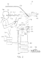
- the picture projection section 115 generates a display object 180 extending from a first view image position PV01 to a second view image position PV02.
- the first view image position PV01 is a position in the view image VI corresponding to the first position P01 on the near side of the position of the preceding vehicle 740 (i.e., on the self-vehicle 730 side).
- the second view image position PV02 is a position in the view image VI corresponding to the second position P02 (course changing position) where the self-vehicle 730 is estimated to change the course.
- the first position P01 is a position in the real space RS, located on the near side of the position P740 of the preceding vehicle 740 (on the self-vehicle 730 side of the preceding vehicle 740).
- the first position P01 is a position between the self-vehicle 730 and the preceding vehicle 740.
- the first position P01 can be located at a prescribed distance on the course ahead of the self-vehicle 730.
- the second position P02 is a position such as a branch point (crossing) of the road and the like where the course change is prompted by e.g. a navigation system. As viewed from the self-vehicle 730, the second position P02 is located ahead of the preceding vehicle 740 (on the opposite side of the position of the preceding vehicle 740 from the first position P01).
- the first view image position PV01 and the second view image position PV02 correspond to the first position P01 and the second position P02 in the real space RS, respectively.
- the display object 180 extends from the first view image position PV01 to the second view image position PV02. As described above, this display object 180 includes depth information.
- a monocular vehicle mounted display system in which a display object indicating the course is perceived at a prescribed position farther than the preceding vehicle.
- FIG. 7 is a graph showing the characteristic of the vehicle mounted display system according to the first embodiment of the invention. More specifically, this figure illustrates an experimental result concerning the vehicle mounted display system 10.
- the preceding vehicle 740 was located at 30 m on the course ahead of the self-vehicle 730.
- the second position P02 (course changing position) where the self-vehicle 730 is estimated to change the course was varied to 30 m, 45 m, 60 m, 75 m, and 120 m from the self-vehicle.
- the position of the display object 180 (position of the tip of the arrow) was specified so as to indicate the second position P02. In this situation, the depth position perceived by the viewer 100 was determined.
- the horizontal axis represents the specified depth distance Ls of the display object 180 (distance between the viewer 100 and the specified depth position).
- the vertical axis represents the subjective depth distance Lsub perceived by the viewer 100 viewing the display object 180 (distance between the viewer 100 and the perceived subjective depth position).
- the dashed line C1 in this figure illustrates the characteristic for the case where the specified depth distance Ls is in agreement with the subjective depth distance Lsub.
- the solid line C2 represents the subjective depth distance Lsub actually determined by experiment.
- the subjective depth distance Lsub is in substantial agreement with the specified depth distance Ls. Furthermore, for instance, in the case where the specified depth distance Ls is set to 120 m, the subjective depth distance Lsub is 105 m. Thus, beyond the distance between the preceding vehicle 740 and the self-vehicle 730, i.e., 30 m, the display object 180 is perceived at a position near the depth specified position ahead of the preceding vehicle 740.
- the configuration of the vehicle mounted display system of comparative examples is similar to the vehicle mounted display system 10 according to the embodiment. However, in the case of the comparative examples, the configuration of the display object 180 is different from that of the embodiment.
- the display object 180 was placed with the second position P02 varied to 30 m, 45 m, 60 m, 75 m, and 120 m from the self-vehicle 730. Then, the depth position perceived by the viewer 100 was determined by experiment. Also in this case, the preceding vehicle 740 is located at 30 m on the course ahead of the self-vehicle 730.
- the display object 180 is generated at the second view image position PV02 corresponding to the second position P02,
- the display object 180 is placed at positions PV30, PV45, PV60, PV75, and PV120 in the view image VI corresponding to the second positions P02 (positions at 30 m, 45 m, 60 m, 75 m, and 120 m from the self-vehicle 730), respectively.
- the size of the display object 180 is varied.
- FIG. 8B illustrates the result of this experiment.
- the subjective depth distance Lsub at which the display object 180 is perceived is greatly different from the specified depth distance Ls.
- the subjective depth distance Lsub is approximately 60 m.
- the display object 180 is perceived on the near side greatly distant from the specified depth position.
- the display object 180 was placed with the second position P02 varied to 30 m, 45 m, 60 m, 75 m, and 120 m from the self-vehicle 730. Then, the depth position perceived by the viewer 100 was determined by experiment. In this case, the experiment was performed in the absence of the preceding vehicle 740 so as to facilitate perceiving the depth position of the display object 180.
- FIG. 9B illustrates the result of this experiment.
- the subjective depth distance Lsub at which the display object 180 is perceived is greatly different from the specified depth distance Ls.
- the subjective depth distance Lsub is approximately 60 m.
- the display object 180 is perceived on the near side greatly distant from the specified depth position.
- the subjective depth distance Lsub is in good agreement with the specified depth distance Ls as compared with the first and second comparative example.
- the vehicle mounted display system 10 can provide a monocular vehicle mounted display system in which a display object indicating the course is perceived at a prescribed position farther than the preceding vehicle.
- the operation of the vehicle mounted display system 10 has been described in the case where the preceding vehicle 740 is located on the course ahead of the self-vehicle, 730.
- the operation in the absence of the preceding vehicle 740 is arbitrary.
- the display object 180 may be generated in a similar manner to the case where the preceding vehicle 740 is present. More specifically, the first position P01 is specified at a prescribed distance on the course ahead of the self-vehicle 730. The second position P02 is specified at a position such as a branch point (crossing) of the road and the like where the course change is prompted. Using the first view image position PV01 and the second view image position PV02 corresponding to the first position P01 and the second position P02, respectively, the display object 180 may be generated so as to extend from the first view image position PV01 to the second view image position PV02 and to include depth information.
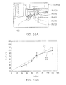
- FIGS. 10A and 10B are schematic views showing an alternative operation and characteristic of the vehicle mounted display system according to the first embodiment of the invention.
- FIG. 10A is a schematic view illustrating the operation
- FIG. 10B is a graph illustrating the characteristic.
- a display object 180 is generated at the second view image position PV02 corresponding to the second position P02 such as a branch point (crossing) of the road and the like where the course change is prompted.
- the display object 180 is placed at positions PV30, PV45, PV60, PV75, and PV120 in the view image VI corresponding thereto.
- the size of the display object 180 is varied.
- the subjective depth distance Lsub is in good agreement with the specified depth distance Ls. More specifically, in the absence of the preceding vehicle 740, the display object 180 is not masked by the image of the preceding vehicle 740. Hence, the display object 180 displayed is perceived accurately at the specified depth position where it is placed.
- the display object 180 is displayed at a predetermined depth position.
- the arrow is directed upward.
- the direction of the arrow of the display object 180 may be rotated to the direction of changing the course without changing the size and shape of the display object 180.
- the shape of the arrow of the display object 180 is gradually changed.
- the tip of the arrow of the display object 180 is placed ahead of the preceding vehicle 740 to indicate the direction of changing the course.
- the display object 180 can be different between in the case of detecting and not detecting the preceding vehicle 740.
- the display mode of the display object 180 can be changed. This facilitates recognizing the difference between the preceding vehicle 740 and the display object 180.
- the position of changing the course such as a crossing can be perceived more clearly.
- FIG. 11 is a flow chart showing the operation of the vehicle mounted display system according to the first embodiment of the invention.
- map information is acquired (step S001).
- an intended position is specified (step S002).
- self-vehicle position information representing the position of the self-vehicle 730 is acquired by e.g. GPS (step S003).
- route information representing a route estimated to be traveled by the self-vehicle 730 is generated (step S004).
- step S003 may be performed inside the vehicle mounted display system 10, or may be performed by e.g. a GPS or radar system provided outside the vehicle mounted display system 10.
- steps S001, S002, and S004 may also be performed inside the vehicle mounted display system 10, or may be performed by a navigation system provided outside the vehicle mounted display system.
- step S005 forward information of the course ahead of the self-vehicle 730 at e.g. each time of traveling is acquired. That is, for the traveling self-vehicle 730, the forward information changing with the passage of time is obtained. This is performed by the forward information acquisition section 410.
- step S006 the position of changing the course is acquired. That is, for the traveling self-vehicle 730, a branch point of changing the course is grasped.
- the preceding vehicle 740 is detected (step S007). This is based on e.g. the image of the preceding vehicle 740 imaged by e.g. a camera, and on a inter vehicle communication (IVC) system, road-vehicle communication (RVC) system, and satellite communication system. Then, information concerning the preceding vehicle 740 is obtained, and a determination is made on the presence or absence of the preceding vehicle 740 (step S008). This is performed by the preceding vehicle information acquisition section 420.
- IVC inter vehicle communication
- RVC road-vehicle communication
- the second position P02 position of changing the course to place the display object 180 is determined (step S009).
- the first position P01 is determined (step S010).
- the first position P01 and the second position P02 may be specified likewise.
- the image of the viewer 100 is imaged by e.g. a camera (step S011), Based thereon, position information of one eye 101 of the viewer 100 is acquired (step S012). This is performed by the position estimation section 210.
- step S013 based on the acquired position information of one eye 101, the difference between the reference position 0(0, h1, 0) and the one eye position E(Ex, Ey, Ez) described with reference to FIGS. 5A and 5B is corrected (step S013).
- a display object 180 is generated (step S014). That is, the process described with reference to FIGS. 5A to 6C is performed.
- step S015 distortion of the image due to the picture formation section 110 and various optical components included in the picture projection section 115 is corrected.
- the above operation is performed by the picture data generation section 130, for instance, of the picture projection section 115. Then, a picture signal including the generated display object 180 is provided to the picture formation section 110. Based thereon, a light beam 112 is generated and projected on one eye 101 of the viewer 100.
- a display object indicating the course can be perceived at a prescribed position farther than the preceding vehicle.
- steps S001-S015 may be interchanged as long as technically feasible, and may be performed simultaneously.
- the end of the display object 180 on the second view image position PV02 side is placed outside the region corresponding to the preceding vehicle 740 in the view image VI. That is, the end of the display object 180 on the second view image position PV02 side is placed outside the image 740I of the preceding vehicle 740.
- This can produce a more accurate perception of the second position P02 (the position such as a branch point of the road and the like where the course change is prompted) corresponding to the second view image position PV02.
- the end of the display object 180 on the second view image position PV02 side is preferably placed at a position which does not overlap the region corresponding to the preceding vehicle 740 in the view image VI.
- the display object 180 can include a continuous shape extending from the first view image position PV01 to the second view image position PV02. This produces a clearer perception of the positions extending from the first view image position PV01 through the preceding vehicle 740 to the second view image position PV02 located ahead of the preceding vehicle 740. Thus, the depth position of the second view image position PV02 can be perceived more accurately.
- the invention is not limited thereto, but the display mode of the display object 180 can be variously modified as described below.
- FIGS. 12A and 12B are schematic views showing an alternative operation and characteristic of the vehicle mounted display system according to the first embodiment of the invention.
- FIG. 12A is a schematic view illustrating the operation
- FIG. 12B is a graph illustrating the characteristic.
- the display object 180 is generated so as to move along a path extending from the first view image position PV01 to the second view image position PV02.
- the display object 180 includes depth information. For instance, the size of the display object 180 is smaller on the second view image position PV02 side than on the first view image position PV01 side.
- the end of the display object 180 on the second view image position PV02 side is placed outside the region corresponding to the preceding vehicle 740 in the view image VI. More specifically, at the second view image position PV02 corresponding to the second position P01 of changing the course, the tip of the arrow of the display object 180 is bent to the direction of changing the course. For instance, at the first view image position PV01, the arrow is directed upward. However, at the second view image position PV02, the arrow is moved horizontally to the position where the arrow tip does not overlap the image of the preceding vehicle 740, and the arrow is directed laterally,
- the subjective depth distance Lsub is in good agreement with the specified depth distance Ls.
- FIGS. 13A and 13B are schematic views showing an alternative operation and characteristic of the vehicle mounted display system according to the first embodiment of the invention.
- FIG. 13A is a schematic view illustrating the operation
- FIG. 13B is a graph illustrating the characteristic.
- the display object 180 is generated so as to move along a path extending from the first view image position PV01 to the second view image position PV02.
- the end of the display object 180 on the second view image position PV02 side is placed inside the region corresponding to the preceding vehicle 740 in the view image VI.
- the subjective depth distance Lsub is in good agreement with the specified depth distance Ls.
- the degree of agreement between the subjective depth distance Lsub and the specified depth distance Ls is higher in the characteristic illustrated in FIG. 12B .
- the end of the display object 180 on the second view image position PV02 side is not masked by the image of the preceding vehicle 740. This can produce a more accurate perception of the depth position of the second view image position PV02 of the display object 180.
- FIG. 14 is a schematic view showing an alternative operation of the vehicle mounted display system according to the first embodiment of the invention.
- the display object 180 includes a plurality of display object elements 180p discretely arranged from the first view image position PV01 to the second view image position PV02.
- the plurality of display object elements 180p are displayed simultaneously.
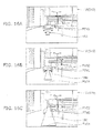
- FIGS. 15A to 15C are schematic views showing an alternative operation of the vehicle mounted display system according to the first embodiment of the invention. More specifically, FIGS. 15A to 15C illustrate the display state of the display object 180 at different times.
- FIG. 15A corresponds to an initial time.
- FIG. 15B corresponds to a time later than FIG. 15A.
- FIG. 15C corresponds to a time later than FIG. 15B .
- the display object 180 includes a plurality of display object elements 180p discretely arranged from the first view image position PV01 to the second view image position PV02.
- the plurality of display object elements 180p are sequentially displayed, and sequentially disappear.
- a first display object element 180p1 disappears at an earlier time than a second display object element 180p2 placed on the second view image position PV02 side of the first display object element 180p1.
- the display object 180 may be displayed like a ticker.
- the number of the plurality of display object elements 180p can be increased to reduce the difference between the first display object element 180p1 on the first view image position PV01 side and the second display object element 180p2 on the second view image position PV02 side.
- This operation corresponds to the operation of moving the display object 180 illustrated in FIGS. 12A to 13B .
- the display object 180 can be generated in arbitrary display modes.
- FIGS. 16A to 16C are schematic views showing an alternative operation of the vehicle mounted display system according to the first embodiment of the invention. More specifically, FIG. 16A illustrates a display object 180 in the case where the self-vehicle 730 is traveling without changing the course. FIG. 16B illustrates a display object 180 in the case of changing the course at an initial time. FIG. 16C illustrates a display object 180 at a time later than FIG. 16B .
- the display object 180 is displayed at e.g. a depth position on the near side of the preceding vehicle 740.
- a first position P01 is specified at a position on the near side of the preceding vehicle 740, and a second position P02 is specified as the position of changing the course.
- the arrow of the display object 180 extends in the direction from the root of the arrow toward the tip of the arrow.
- the tip of the arrow of the display object 180 is specified at the position of the second view image position PV02 corresponding to the second position P02.
- the traveling direction at the crossing of changing the course is indicated by the bend at the tip of the arrow of the display object 180.
- the root portion of the arrow of the display object 180 is displayed in a large (thick) size.
- the tip portion of the arrow is displayed in a small (thin) size. Thus, information concerning the depth is indicated.
- At least part of the display object 180 is preferably placed at a position in the view image VI corresponding to a position on the surface of the road of the course ahead. This can produce a more accurate perception of the depth position of the display object 180.
- the picture formation section 110 can be based on, besides LCD, various optical switches such as DMD (digital micromirror device) and MEMS (microelectromechanical system). Furthermore, the picture formation section 110 can also be based on a laser projector or LED (light emitting diode) projector. In this case, the picture is formed by a laser beam.
- the picture formation section 110 based on LCD using an LED as a light source can serve for downsizing and power saving of the device.
- a lenticular lens 120b is used as a means for controlling the divergence angle of the light beam 112.
- a diffusion plate with a controlled diffusion angle can also be used.
- the mirror 126 can be subjected to angle adjustment by the actuator section 126a. Besides a plane mirror, the mirror 126 can be a concave mirror serving as a reflective surface with power. Also in this case, its angle can be changed by the actuator section 126a.
- the displayed picture may undergo distortion of the image depending on e.g. the angle of the mirror 126.
- distortion correction in the picture data generation section 130 a distortion-free picture can be presented to the viewer 100.
- the light beam 112 with a controlled divergence angle reaches the viewer 100.
- the viewer 100 views the picture with one eye 101.
- the spacing between the eyes of the viewer 100 is 6 cm on average.
- the picture is not projected on both eyes.
- the picture is preferably projected on the dominant eye of the viewer 100.
- control section 250 controls the actuator section 126a coupled to the mirror 126 constituting part of the projection section 120 to control the angle of the mirror 126.
- the control section 250 may control the picture formation section 110 to adjust e.g. the brightness and contrast of the picture.
- the control section 250 automatically adjust at least one of the projection range 114a and the projection position 114 of the light beam 112.
- the invention is not limited thereto.
- at least one of the projection range 114a and the projection position 114 of the light beam 112 may be manually adjusted.
- the actuator section 126a can be manually controlled to control the angle of the mirror 126.
- the picture data generation section 130 generates data concerning a picture including a display object 180 based on the forward information acquired by the forward information acquisition section 410 and the estimated position of one eye 101 of the viewer 100.
- the display object 180 may be generated based on the forward information acquired by the forward information acquisition section 410.
- data concerning a picture including a display object 180 is generated based on the forward information and the position of one eye 101.
- a technique concerning person authentication described in e.g. Japanese Patent No. 3279913 is used to recognize the face of the viewer 100 and to calculate the position of the eye as a face component.
- the position of one eye 101 of the viewer 100 on which a picture is to be projected is determined and estimated.
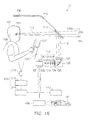
- FIG. 17 is a schematic view showing the configuration of an alternative vehicle mounted display system according to the first embodiment of the invention.
- the alternative vehicle mounted display system 11 according to the embodiment further includes a forward information detection section 424 and a route generation section 450.
- the rest of the configuration can be made similar to that of the vehicle mounted display system 10, and hence the description thereof is omitted.
- the forward information detection section 424 includes e.g. a forward imaging section 421 (camera), an image analysis section 422, and a forward information generation section 423.
- the image analysis section 422 analyzes the image imaged by the forward imaging section 421.
- the forward information generation section 423 extracts various pieces of information concerning the shape and obstacles of the road and crossing from the image analyzed by the image analysis section 422 to generate forward information.
- forward information data concerning the situation of the road ahead (such as the shape of the road and crossing) detected by the forward information detection section 424 is acquired.
- the forward information detected by the forward information detection section 424 is supplied to the forward information acquisition section 410.
- the forward information detection section 424 can also detect information concerning the preceding vehicle 740 by analyzing the image imaged by the forward imaging section 421.
- the preceding vehicle information detected by the forward information detection section 424 may be supplied to the preceding vehicle information acquisition section 420.
- the forward information detection section 424 may be incorporated in the forward information acquisition section 410 or the preceding vehicle information acquisition section 420.
- the route generation section 450 generates route information of a route inferred to be traveled by the self-vehicle 730.
- the route generation section 450 calculates a route inferred to be traveled by the self-vehicle 730.
- a route inferred to be traveled by the self-vehicle 730 For instance, for instance, several route candidates may be calculated.
- the viewer 100, who is the driver of the self-vehicle 730, may be prompted to select one of the candidates. Based on the result of the selection, the route may be determined.
- a display object 180 is generated.
- This route generation section 450 may be incorporated in e.g. the picture data generation section 130. Alternatively, the route generation section 450 may be incorporated in various components incorporated in the vehicle mounted display system.
- This route generation section 450 may not be provided in the vehicle mounted display system 11.
- a navigation system separately provided in the self-vehicle 730 may include a section corresponding to the route generation section 450.
- the route inferred to be traveled by the self-vehicle 730 may be generated by the navigation system.
- the picture data generation section 130 may obtain this route and generate picture data including a display object 180.
- the section corresponding to the route generation section 450 may be provided separately from the self-vehicle 730.
- the picture data generation section 130 can obtain the data from the section corresponding to the route generation section 450 provided separately from the self-vehicle 730 and generate picture data including a display object 180.
- route generation section 450 (and the section corresponding thereto) can be provided anywhere.
- FIG. 18 is a schematic view showing the configuration of an alternative vehicle mounted display system according to the first embodiment of the invention.
- the configuration of the picture projection section 115 is different from that of the vehicle mounted display system 10 illustrated in FIG. 2 .
- the configuration of the picture formation section 110 and the projection section 120 is different.
- the example does not include the control section 250.
- the rest of the configuration is similar to that of the vehicle mounted display system 10, and hence the description thereof is omitted.
- the picture formation section 110 can be based on e.g. various optical switches such as LCD, DMD, and MEMS. Alternatively, the picture formation section 110 can also be based on a laser projector or LED projector.
- the projection section 120 includes e.g. a light source 121, a tapered light guide 122, a first lens 123, a variable aperture 124, a second lens 125, a mirror 126 of e.g. the concave movable type, and an aspherical Fresnel lens 127.
- the focal distance of the first lens 123 is denoted by f1
- the focal distance of the second lens 125 is denoted by f2.
- the variable aperture 124 is placed at a distance of f1 from the first lens 123 and at a distance of f2 from the second lens 125.
- the light beam emitted from the second lens 125 is injected into the picture formation section 110. Based on the picture formed by the picture formation section 110, the light beam is modulated into a light beam 112.
- the light beam 112 passes through the mirror 126 and the aspherical Fresnel lens 127.
- the light beam 112 is then reflected by the reflector 711 of the windshield 710 of the self-vehicle 730 on which the vehicle mounted display system 12 is mounted.
- the light beam 112 is then projected on one eye 101 of the viewer 100.
- the light source 121 can be one of various light sources such as LED, high pressure mercury lamp, halogen lamp, and laser.
- the aspherical Fresnel lens 127 can be designed e.g. in accordance with the shape of the windshield 710 so that the shape (such as cross-sectional shape) of the light beam 112 can be controlled.
- FIG. 19 is a flow chart showing the display method according to the second embodiment of the invention.
- step SS1 forward information concerning the course ahead of the self-vehicle 730 is acquired.
- step SS2 preceding vehicle information concerning the preceding vehicle 740 located on the course ahead is acquired.
- step SS3 the position of one eye 101 of the viewer 100 riding in the self-vehicle 730 is estimated.
- step SS4 the view image VI of the viewer 100 viewing the course ahead of the self-vehicle 730 is estimated.
- a display object 180 is generated (step SS5).
- the display object 180 extends from a first view image position PV01 to a second view image position PV02 and includes depth information.
- the first view image position PV01 is a position in the view image VI corresponding to the first position P01 on the self-vehicle 730 side of the position of the preceding vehicle 740.
- the second view image position PV02 is a position in the view image VI corresponding to the second position P02 where the self-vehicle 730 is estimated to change the course.
- the second position P02 is located on the opposite side of the position of the preceding vehicle 740 from the first position P01.
- a light beam 112 including a picture including the display object 180 is generated (step SS6). Then, based on the estimated position of one eye 101, the light beam 112 is projected toward one eye 101 of the viewer 100 (step SS7).
- a monocular display method in which the display object indicating the course is perceived at a prescribed position farther than the preceding vehicle.
- steps SS1-SS7 may be interchanged as long as technically feasible, and may be performed simultaneously.
- the vehicle according to the embodiment is the aforementioned self-vehicle 730. More specifically, as illustrated in FIG. 2 , the self-vehicle 730 includes one of the vehicle mounted display systems according to the first embodiment, and a windshield 710 causing the light beam 112 emitted from the vehicle mounted display system to be reflected toward the viewer 100.
- the self-vehicle 730 includes the vehicle mounted display system 10 e.g. behind the dashboard 720 of the self-vehicle 730 as viewed from the viewer 100.
- a vehicle capable of providing a monocular display in which a display object indicating the course is perceived at a prescribed position farther than the preceding vehicle.
- a monocular vehicle mounted display system display method, and vehicle in which a display object indicating the course is perceived at a prescribed position farther than the preceding vehicle.
Landscapes
- Engineering & Computer Science (AREA)
- Physics & Mathematics (AREA)
- General Physics & Mathematics (AREA)
- Remote Sensing (AREA)
- Radar, Positioning & Navigation (AREA)
- General Engineering & Computer Science (AREA)
- Automation & Control Theory (AREA)
- Theoretical Computer Science (AREA)
- Human Computer Interaction (AREA)
- Optics & Photonics (AREA)
- Instrument Panels (AREA)
- Navigation (AREA)
- Fittings On The Vehicle Exterior For Carrying Loads, And Devices For Holding Or Mounting Articles (AREA)
- Testing, Inspecting, Measuring Of Stereoscopic Televisions And Televisions (AREA)
Abstract

Description
- This invention relates to a vehicle mounted display system, a display method, and a vehicle.
- As a vehicle mounted display device, a HUD (head-up display) has been developed. By the HUD, vehicle information, including traveling information such as vehicle speed and navigation information to the destination, is projected on the windshield so that the external information and the vehicle information are made simultaneously viewable.
- The HUD can present an intuitive display to the viewing person. It has been proposed to display information such as a route display in accord with the background observed by the driver. For instance, a method for changing the displayed figure in response to the external situation (Patent Document 1) and a method for changing the size of the displayed image in response to the vehicle speed (Patent Document 2) are proposed.
- In conventional HUDs including these techniques, the display of the HUD is observed by both eyes. The depth position of the virtual image displayed by the HUD is an optically designed position (optical display position). In many cases, this position is set at 2-3 m ahead of the driver. Hence, in the case of the binocular HUD, when the driver tries to view the display of the HUD simultaneously with viewing the far distance during driving, the display object of the HUD is perceived as a double image and very difficult to see. Conversely, if the driver tries to view the display of the HUD, the displayed image is perceived at 2-3 m ahead due to binocular parallax. Thus, it is difficult to simultaneously perceive the far distance in the background.
- Furthermore, the displayed image of the HUD is reflected by e.g. the windshield and observed. Thus, a double image occurs due to the thickness of the reflection screen of the windshield. This also makes the display difficult to see.
- To resolve such viewing difficulty due to binocular parallax, a monocular HUD for observing the displayed image with one eye has been proposed. In an example technique, the displayed image is presented only to one eye for the purpose of eliminating binocular parallax and causing the depth position of the object displayed by the HUD to appear farther than the optical display position.
A technique for presenting a displayed image only to one eye in order to prevent the aforementioned double image (Patent Document 3) is proposed. - In such a monocular HUD, in the case where there is a preceding vehicle ahead, the display object overlapping the preceding vehicle is displayed on the near side of the preceding vehicle. Thus, by the masking effect, the display object looks like standing on the near side of the preceding vehicle. Hence, it is difficult to cause the display object to be perceived farther than the preceding vehicle. In particular, in the case of navigation display for route guidance, it is difficult to display the corner located at a position farther than the preceding vehicle.
-
- [Patent Citation 1]
JP-A 2006-284458 - [Patent Citation 2]
JP-A 2006-17626 - [Patent Citation 3]
JP-A 7-228172 (1995 - The invention provides a monocular vehicle mounted display system, display method, and vehicle in which a display object indicating the course is perceived at a prescribed position farther than the preceding vehicle.
- According to an aspect of the invention, there is provided a vehicle mounted display system comprising: a forward information acquisition section configured to acquire forward information concerning a course ahead of a self-vehicle; a preceding vehicle information acquisition section configured to acquire preceding vehicle information concerning a preceding vehicle located on the course ahead; a position estimation section configured to estimate a position of one eye of a viewer riding in the self-vehicle; and a picture projection section configured to generate a light beam including picture information including a display object, and to project the light beam toward the one eye of the viewer based on the position of the one eye, based on the forward information and the position of the one eye, the picture projection section estimating a view image of the viewer viewing the course ahead of the self-vehicle, and the picture projection section including a picture data generation section configured to generate the display object extending from a first view image position to a second view image position and including depth information, the first view image position being a position in the view image corresponding to a first position on the self-vehicle side of a position of the preceding vehicle acquired by the preceding vehicle information acquisition section, the second view image position being a position in the view image corresponding to a second position where the self-vehicle is estimated to change the course, the second position being located on opposite side of the position of the preceding vehicle from the first position.
- According to another aspect of the invention, there is provided a display method comprising: acquiring forward information concerning a course ahead of a self-vehicle; acquiring preceding vehicle information concerning a preceding vehicle located on the course ahead; estimating a position of one eye of a viewer riding in the self-vehicle; estimating a view image of the viewer viewing the course ahead of the self-vehicle based on the forward information and the position of the one eye; generating the display object extending from a first view image position to a second view image position and including depth information, the first view image position being a position in the view image corresponding to a first position on the self-vehicle side of a position of the preceding vehicle, the second view image position being a position in the view image corresponding to a second position where the self-vehicle is estimated to change the course, the second position being located on opposite side of the position of the preceding vehicle from the first position; generating a light beam including a picture including the display object; and projecting the light beam toward the one eye of the viewer based on the position of the one eye.
- According to another aspect of the invention, there is provided a vehicle comprising: the vehicle mounted display system above described; and a windshield configured to cause the light beam emitted from the vehicle mounted display system to be reflected toward the viewer.
- According to the invention, there are provided a monocular vehicle mounted display system, display method, and vehicle in which a display object indicating the course is perceived at a prescribed position farther than the preceding vehicle.
-
- [
Fig. 1 ]
FIG. 1A and FIG. 1B are schematic views showing the operation of a vehicle mounted display system according to a first embodiment of the invention. - [
Fig. 2 ]
FIG. 2 is a schematic view showing the configuration of the vehicle mounted display system according to the first embodiment of the invention. - [
Fig. 3 ]
FIG. 3 is a schematic view showing the operating state of the vehicle mounted display system according to the first embodiment of the invention. - [
Fig. 4 ]
FIG. 4 is a schematic view showing the operation of the vehicle mounted display system according to the first embodiment of the invention. - [
Fig. 5 ]
FIG. 5A and FIG. 5B are schematic views showing the operation of the vehicle mounted display system according to the first embodiment of the invention. - [
Fig. 6 ]
FIG. 6A, FIG. 6B and FIG. 6C are schematic views showing the operation of the vehicle mounted display system according to the first embodiment of the invention. - [
Fig. 7 ]
FIG. 7 is a graph showing the characteristic of the vehicle mounted display system according to the first embodiment of the invention. - [
Fig. 8 ]
FIG. 8A and FIG. 8B are schematic views showing the operation and characteristic of a vehicle mounted display system of a first comparative example, - [
Fig. 9 ]
FIGS. 9A and 9B are schematic views showing the operation and characteristic of a vehicle mounted display system of a second comparative example. - [
Fig. 10 ]
FIG. 10A and FIG. 10B are schematic views showing an alternative operation and characteristic of the vehicle mounted display system according to the first embodiment of the invention. - [
Fig. 11 ]
FIG. 11 is a flow chart showing the operation of the vehicle mounted display system according to the first embodiment of the invention. - [
Fig. 12 ]
FIG. 12A and FIG. 12B are schematic views showing an alternative operation and characteristic of the vehicle mounted display system according to the first embodiment of the invention. - [
Fig. 13 ]
FIG. 13A and FIG. 13B are schematic views showing an alternative operation and characteristic of the vehicle mounted display system according to the first embodiment of the invention. - [
Fig. 14 ]
FIG. 14 is a schematic view showing an alternative operation of the vehicle mounted display system according to the first embodiment of the invention. - [
Fig. 15 ]
FIG. 15A, FIG. 15B and FIG. 15C are schematic views showing an alternative operation of the vehicle mounted display system according to the first embodiment of the invention. - [
Fig. 16 ]
FIG. 16A, FIG. 16B and FIG. 16C are schematic views showing an alternative operation of the vehicle mounted display system according to the first embodiment of the invention. - [
Fig. 17 ]
FIG. 17 is a schematic view showing the configuration of an alternative vehicle mounted display system according to the first embodiment of the invention. - [
Fig. 18 ]
FIG. 18 is a schematic view showing the configuration of an alternative vehicle mounted display system according to the first embodiment of the invention. - [
Fig. 19 ]
FIG. 19 is a flow chart showing the display method according to the second embodiment of the invention. - Embodiments of the invention will now be described in detail with reference to the drawings.
In the present specification and the drawings, components similar to those described previously with reference to earlier figures are labeled with like reference numerals, and the detailed description thereof is omitted as appropriate. -
-
FIGS. 1A and 1B are schematic views showing the operation of a vehicle mounted display system according to a first embodiment of the invention. -
FIG. 2 is a schematic view showing the configuration of the vehicle mounted display system according to the embodiment. -
FIG. 3 is a schematic view showing the operating state of the vehicle mounted display system according to the embodiment. -
FIGS. 4 to 6C are schematic views showing the operation of the vehicle mounted display system according to the embodiment. - First, with reference to
FIGS. 2 to 6C , the configuration and operation of the vehicle mounted display system according to the embodiment are outlined.
As shown inFIG. 2 , the vehicle mounteddisplay system 10 according to the embodiment includes a forwardinformation acquisition section 410, a preceding vehicleinformation acquisition section 420, aposition estimation section 210, and apicture projection section 115. - The forward
information acquisition section 410 acquires forward information, which is information concerning the course ahead of the self-vehicle 730. The preceding vehicleinformation acquisition section 420 acquires preceding vehicle information concerning the precedingvehicle 740 located on the course ahead of the self-vehicle 730. Theposition estimation section 210 estimates the position of oneeye 101 of theviewer 100 riding in the self-vehicle 730. Thepicture projection section 115 projects alight beam 112 including a picture including adisplay object 180 toward oneeye 101 of theviewer 100 based on the estimated position of oneeye 101. - The self-
vehicle 730 is a vehicle such as an automobile. Theviewer 100 is the driver (operator) driving the automobile. That is, the self-vehicle 730 is a vehicle on which the vehicle mounteddisplay system 10 according to the embodiment is mounted. - The forward information is information concerning the course ahead of the self-
vehicle 730. The forward information is information concerning the course ahead with respect to the traveling direction estimated for the self-vehicle 730. The forward information includes e.g. the shape of the road and crossing. - The forward
information acquisition section 410 acquires forward information based on e.g. the image ahead of the self-vehicle 730 imaged by a camera. Alternatively, for instance, based on the position of the self-vehicle 730 determined using the GPS (global positioning system) function, the forward information is acquired using various communication functions. Alternatively, for instance, an imaging function or radar function installed on e.g. the road or building can communicate with various databases coupled thereto, and the forward information may be acquired by this communication. Thus, the method for acquiring forward information in the forwardinformation acquisition section 410 is arbitrary. - The preceding
vehicle 740 is e.g. a vehicle located on the course ahead of the self-vehicle 730 within a predetermined distance from the self-vehicle 730. For instance, this predetermined distance can be changed with various situations such as the traveling speed of the self-vehicle 730 and the width of the road traveled by the self-vehicle 730. - The preceding vehicle
information acquisition section 420 acquires preceding vehicle information concerning this precedingvehicle 740. The preceding vehicle information includes information concerning the presence or absence of the precedingvehicle 740. More specifically, for instance, if the preceding vehicle information representing the presence within a predetermined distance from the self-vehicle 730 is acquired, it is determined that the precedingvehicle 740 is present. Otherwise, it is determined that the precedingvehicle 740 is absent. - The preceding vehicle
information acquisition section 420 acquires preceding vehicle information based on e.g. the image of the precedingvehicle 740 imaged by a camera. Alternatively, for instance, the preceding vehicle information is acquired using a vehicle-vehicle communication system and road-vehicle communication system. Alternatively, for instance, the preceding vehicle information is acquired by exchanging the position information of the self-vehicle 730 and the other vehicle through e.g. a satellite communication system. Thus, the method for acquiring preceding vehicle information in the preceding vehicleinformation acquisition section 420 is arbitrary. - The
display object 180 is provided in the picture which the vehicle mounteddisplay system 10 presents to theviewer 100. Thedisplay object 180 is a display content including e.g. the arrow indicating the traveling direction. For instance, thedisplay object 180 relates to traveling information of the self-vehicle 730 on which the vehicle mounteddisplay system 10 is mounted. More specifically, thedisplay object 180 is e.g. an arrow indicating the route in a navigation system. - Such a
display object 180 is generated based on e.g. the traveling direction expected for the self-vehicle 730. The traveling direction is determined by the route and the position of the self-vehicle 730. The route is determined by a navigation system for generating a route to the destination from map information. The position of the self-vehicle 730 is determined by e.g. GPS. Here, the section for determining the route and the section for determining the position of the self-vehicle 730 described above may be incorporated inside the vehicle mounteddisplay system 10, or incorporated in the self-vehicle 730 on which the vehicle mounteddisplay system 10 is mounted. - As illustrated in
FIG. 2 , the vehicle mounteddisplay system 10 is provided in e.g. the self-vehicle 730. More specifically, for instance, the vehicle mounteddisplay system 10 is provided behind thedashboard 720 of the self-vehicle 730 as viewed from theviewer 100, who is the driver. - The
picture projection section 115 includes e.g. a picturedata generation section 130, a picture formation section 110, and aprojection section 120. - The picture
data generation section 130 generates data concerning a picture including adisplay object 180. Then, the picture signal including the picture data generated by the picturedata generation section 130 is supplied to the picture formation section 110. - The picture formation section 110 forms a picture on e.g. the screen of the picture formation section 110 based on the picture signal supplied from the picture
data generation section 130. The picture formation section 110 can be e.g. a liquid crystal display LCD including a light source. - The
projection section 120 projects the picture formed by the picture formation section 110 onto oneeye 101 of theviewer 100. - The
projection section 120 is composed of e.g. a projector lens, a mirror, and various optical elements for controlling the divergence angle (diffusion angle). As the case may be, theprojection section 120 includes a light source.
In the example, theprojection section 120 is composed of animaging lens 120a, alenticular lens 120b for controlling the divergence angle, amirror 126, and anaspherical Fresnel lens 127. - The
light beam 112 emitted from the picture formation section 110 passes through theimaging lens 120a, thelenticular lens 120b, themirror 126, and theaspherical Fresnel lens 127. Thelight beam 112 is then reflected by a reflector 711 (translucent reflector) provided on e.g. the windshield 710 (transparent plate) of the self-vehicle 730 on which the vehicle mounteddisplay system 10 is mounted. Thelight beam 112 is then projected on oneeye 101 of theviewer 100. Then, theviewer 100 perceives the virtual image 310 of thedisplay object 180 formed at the virtualimage formation position 310a through thereflector 711. - Here, the configuration of the
picture projection section 115 is arbitrary. For instance, the configuration of each of the picturedata generation section 130, the picture formation section 110, and theprojection section 120 described above is also arbitrary. These can be variously modified as described later. - On the other hand, the
position estimation section 210 estimates oneeye 101 of theviewer 100 on which the picture is projected. Theposition estimation section 210 can include e.g. animaging section 211 for imaging theviewer 100, animage processing section 212 for processing the image imaged by theimaging section 211, and acalculation section 213 for determining and estimating the position of oneeye 101 of theviewer 100 based on the data image-processed by theimage processing section 212. - Here, the
imaging section 211 is placed on e.g. the front or lateral side of the driver seat of the self-vehicle 730. For instance, theimaging section 211 images the image of the face of theviewer 100, who is the driver. Thus, as described above, the position of oneeye 101 of the viewer is estimated. - Furthermore, in the example, a
control section 250 is further provided. Thecontrol section 250 controls thepicture projection section 115 based on the position of oneeye 101 of theviewer 100 estimated by theposition estimation section 210. Thus, thecontrol section 250 can adjust at least one of theprojection range 114a and theprojection position 114 of thelight beam 112. - For instance, the
control section 250 controls anactuator section 126a coupled to themirror 126 constituting part of theprojection section 120. Thus, by controlling the angle of themirror 126, thecontrol section 250 controls theprojection position 114. Hence, even when thehead 105 of theviewer 100 moves, the presentation position of the picture can be controlled following the movement. This eliminates deviation from the picture presentation position due to the movement of thehead 105 of theviewer 100. Thus, the practical viewing range can be expanded. - As shown in
FIG. 3 , in the vehicle mounteddisplay system 10 according to the embodiment, thedisplay object 180 is displayed in adisplay picture 510 projected on the reflector 711 (not shown) of thewindshield 710. Hence, theviewer 100 simultaneously views theexternal picture 520 and thedisplay picture 510. Thus, the vehicle mounteddisplay system 10 is used as a vehicle mounted HUD. - Here, the position of the
display object 180 in thedisplay picture 510 is controlled in accordance with the position of theexternal picture 520.
Besides such adisplay object 180, thedisplay picture 510 can include e.g. thecurrent position 511, the surroundingbuilding information 512, and thevehicle information 514 such as speed and fuel, which are controlled independent of theexternal picture 520. - The HUD can produce a display superimposed on the background (external picture 520). Hence, advantageously, the
viewer 100 can intuitively grasp the display. In particular, the monocular HUD enables a viewer to simultaneously view the HUD display even if the point of regard of theviewer 100 is located distantly. Thus, the monocular HUD is suitable for a display superimposed on the external environment. - The picture
data generation section 130, for instance, of thepicture projection section 115 for generating thedisplay object 180 can have a virtual picture space. This virtual picture space is associated with the real space with reference to the display position of the virtual image where thedisplay object 180 is displayed. Thedisplay object 180 is generated so that the coordinate position in the virtual picture space is reflected in the real space. - As shown in
FIG. 4 , in the vehicle mounteddisplay system 10, thedisplay object 180 is generated at a position in the view image VI of theviewer 100. This position corresponds to the intended position in the real space RS indicated by thedisplay object 180. - That is, based on the forward information acquired by the forward
information acquisition section 410 and the position of oneeye 101 estimated by theposition estimation section 210, thepicture projection section 115 estimates the view image VI of theviewer 100 viewing the course ahead of the self-vehicle 730. For instance, thepicture projection section 115 estimates how theviewer 100 views theforward information 530 such as the road of the course viewed ahead. In the estimated view image VI, thepicture projection section 115 estimates animage 530v corresponding to theforward information 530 such as the road in the real space RS. Here, theimage 530v may not be formed as an actual image, but may be a virtual position corresponding to the position of theforward information 530 in the real space RS. - Then, based on the estimated view image VI, the
display object 180 is generated so that thedisplay object 180 is placed at a position in the view image VI (position 521v in the view image VI) corresponding to the intended position (target position 521) on the course ahead.
An example of the method for estimating the view image VI and placing thedisplay object 180 described above will be described later. - Then, the
picture projection section 115 generates alight beam 112 including a picture including thedisplay object 180. Based on the position of oneeye 101 estimated by theposition estimation section 210, thepicture projection section 115 projects thelight beam 112 toward oneeye 101 of theviewer 100. - Thus, the
viewer 100 views thedisplay object 180 generated in the view image VI as a superimposition on the background image of the course ahead corresponding to thedisplay object 180. Hence, theviewer 100 can view the background image and thedisplay object 180 without sense of strangeness. - Here, the three-dimensional axes (x axis, y axis, and z axis) in the real space on the course ahead can be associated with three-dimensional axes (x1 axis, y1 axis, and z1 axis) defined in the view image VI. Furthermore, three-dimensional axes (α axis, β axis, and γ axis) can be defined in the virtual space VS corresponding to the view image VI.
- For instance, the z axis is defined as the traveling direction of the self-
vehicle 730. The x-axis direction is the horizontal direction. The y axis is defined as the vertical direction. Then, the x1 axis, y1 axis, and z1 axis are axes in the view image VI corresponding to the x axis, y axis, and z axis, respectively. The α axis, β axis, and γ axis are axes in the virtual space VS corresponding to the x axis, y axis, and z axis, respectively. - Here, it can be assumed that in the three-dimensional space of the view image VI, the distance between the
viewer 100 and the view image VI (distance in the z1 direction) is constant. Then, the view image VI can be assumed to include e.g. a two-dimensional space (plane) with a vertical axis Va (corresponding to the y1 axis) and a horizontal axis Ha (corresponding to the x1 axis). - Then, for instance, at a prescribed position in the virtual space VS, a
virtual viewpoint 101a is specified. Thedisplay object 180 is generated so that thedisplay object 180 includes depth information when thedisplay object 180v in the virtual space VS is viewed from the position of thevirtual viewpoint 101a. - That is, the size and shape, for instance, of the
display object 180 are controlled so that thedisplay object 180 includes depth information in the virtual space VS corresponding to the depth in the real space RS. Thedisplay object 180 includes depth information based on e.g. the law of perspective. - For instance, in the virtual space VS, on the near side to the
virtual viewpoint 101a, thedisplay object 180 is controlled to be larger. On the far side, thedisplay object 180 is controlled to be smaller.
Here, the size of thedisplay object 180 superimposed on the view image VI becomes smaller upward (in the increasing direction of the value of y1), and becomes larger downward (in the decreasing direction of the value of y1), - Thus, the
viewer 100 viewing thedisplay object 180 can perceive thedisplay object 180 more easily at the depth position in the real space RS where thedisplay object 180 is to be perceived. - Here, as illustrated in
FIG. 4 , the shape of thedisplay object 180 can be e.g. a curved arrow or a shape having an inflection point at the location of changing the course. The shape includes depth information as described above. - In the following, an example of the method for estimating the view image VI is described.
FIGS. 5A and 5B illustrate a coordinate system in the vehicle mounteddisplay system 10. More specifically,FIG. 5A is a schematic view as viewed from above the head of theviewer 100.FIG. 5B is a schematic view as viewed from the lateral side of theviewer 100. - Here, as shown in
FIGS. 5A and 5B , in the (x, y, z) coordinate system, the position of one viewing eye (e.g., dominant eye, such as right eye) 101 of theviewer 100 is referred to as one eye position E(Ex, Ey, Ez).
The position where thelight beam 112 including thedisplay object 180 formed by the vehicle mounteddisplay system 10 according to the embodiment is reflected on thereflector 711 of the self-vehicle 730 is referred to as view image position P(Px, Py, Pz), which is a position in the view image VI. - Here, a prescribed reference position O(0, h1, 0) is defined. The origin of the coordinate axes is located in contact with the ground and defined as (0, 0, 0). That is, the reference position O is located at the position of height h1 from the origin of the coordinate axes.
- As viewed from the aforementioned prescribed reference position O, an arbitrary position on the course ahead of the self-
vehicle 730 is referred to as real space position Q(Qx, Qy, Qz). The real space position Q(Qx, Qy, Qz) is determined based on the forward information acquired by the forwardinformation acquisition section 410. - As viewed from the reference position O, the shift amount in the x-axis direction of the one eye position E is denoted by w1, the shift amount in the x-axis direction of the view image position P is denoted by w2, and the shift amount in the x-axis direction of the real space position Q is denoted by w3.
On the other hand, as viewed from the origin of the coordinate axes, the shift amount in the y-axis direction of the one eye position E is Ey. As viewed from the reference position O, the shift amount in the y-axis direction of the view image position P is h1-h2, and the shift amount in the y-axis direction of the real space position Q is h1-h3. - The distance in the z-axis direction between the reference position O and the view image position P is referred to as distance I. The distance in the z-axis direction between the reference position O and the real space position Q is referred to as distance L.
- The real space position Q(Qx, Qy, Qz) includes data concerning the depth information, Qz. However, in the view image VI, such a real space position Q(Qx, Qy, Qz) is estimated as a two-dimensional position in the x1-y1 plane. Hence, the following description refers to the x-axis direction and the y-axis direction corresponding to the x1-axis direction and the y1-axis direction.
- As illustrated in
FIG. 5A , with regard to the x-axis direction, the ratio between the shift amount w3 from the x axis of the real space position Q and the shift amount w2 from the x axis of the view image position P(Px, Py) is equal to the ratio between the distance L and the distance I. Hence, when oneeye 101 of theviewer 100 is located at the reference position O, the value in the x-axis direction of the view image position P(Px, Py), i.e., the shift amount w2, is given by w3xI/L. If oneeye 101 of theviewer 100 is displaced from the reference position O, the value can be corrected by the amount of displacement, i.e., the distance Ex (w1). - On the other hand, as illustrated in
FIG. 5B , with regard to the y-axis direction, the ratio between the shift amount h1-h3 in the y-axis direction of the real space position Q(Qx, Qy) and the shift amount h1-h2 in the y-axis direction of the view image position P(Px, Py) is equal to the ratio between the distance L and the distance I. Hence, when oneeye 101 of theviewer 100 is located at the reference position O, the value in the y-axis direction of the view image position P(Px, Py), i.e., the shift amount h1-h2, is given by (h1-h3)×I/L. If oneeye 101 of theviewer 100 is displaced from the reference position O, the value can be corrected by the amount of displacement, i.e., the distance h1-Ey. - Thus, it is possible to estimate the view image position P in the view image VI corresponding to the real space position Q in the real space RS on the course ahead of the self-
vehicle 730 as viewed by theviewer 100. - By a method similar to the above method for estimating the view image VI from the real space RS, a
display object 180 can be generated at a position in the view image VI corresponding to the intended position in the real space RS indicated by thedisplay object 180. - For instance, consider the case of placing a
display object 180 at the view image position P(Px, Py, Pz). Then, the position to place thedisplay object 180 refers to the position of each point included in thedisplay object 180. - As viewed from the aforementioned prescribed reference position O, the position where the virtual image of the
display object 180 is perceived in the real space is defined as the aforementioned real space position Q(Qx, Qy, Qz). Here, the distance L is a specified depth distance in specifying thedisplay object 180. That is, the position at the specified depth distance as viewed from the reference position O is the intended depth position. - The ratio of the shift amount w3 to the shift amount w2 is equal to the ratio of the distance L to the distance I. Furthermore, the ratio of the shift amount h1-h3 to the shift amount h1-h2 is equal to the ratio of the distance L to the distance I. Based on these equalities, the
display object 180 can be generated at a prescribed position in the view image VI corresponding to the real space RS. -
FIG. 6A illustrates the one eye position E(Ex, Ey). More specifically, this figure illustrates an imaged image of thehead 105 of theviewer 100 imaged by theimaging section 211. As shown in this figure, this imaged image is processed by theimage processing section 212. Then, by thecalculation section 213, the position of oneeye 101 of theviewer 100 is determined and estimated. Thus, the one eye position E(Ex, Ey), which is the position of oneeye 101 as viewed from the reference position O, is estimated by theposition estimation section 210. That is, Ex and Ey are calculated by theposition estimation section 210. -
FIG. 6B illustrates the view image position P(Px, Py), which is the target position in the view image VI where thedisplay object 180 is placed. This figure illustrates animage 530v of the forward information (such as the width and shape of the road) acquired by the forwardinformation acquisition section 410. The view image position P(Px, Py) corresponding to the target position to display thedisplay object 180 is determined. That is, on the road traveled by the self-vehicle 730, the position corresponding to the position to display thedisplay object 180 is determined as the view image position P(Px, Py). -
FIG. 6C illustrates the display object position P1(Px1, Py1) of thedisplay object 180 perceived as a superimposition on the view image VI. More specifically, this figure illustrates the display object position P1(Px1, Py1), which is the position of thedisplay object 180 projected on thereflector 711 of the self-vehicle 730 by the vehicle mounteddisplay system 10. This display object position P1(Px1, Py1) is determined based on the aforementioned one eye position E(Ex, Ey) and the view image position P(Px, Py) corresponding to the target position. - Thus, with regard to the
forward information 530 such as the road of the course ahead viewed by theviewer 100, animage 530v corresponding to theforward information 530 in the view image VI is estimated. Hence, each position of thedisplay object 180 is generated so as to be placed at a position in the view image VI corresponding to the real space RS. -
-
FIG. 1A schematically illustrates a view image VI and adisplay object 180 in the picture (display picture 510) included in thelight beam 112 and the background of the course ahead of the self-vehicle 730 as viewed by theviewer 100. -
FIG. 1B illustrates adisplay object 180 of the picture (display picture 510) included in thelight beam 112. - As shown in
FIG. 1A , the view image VI includes information on forward information concerning the road and the like ahead and preceding vehicle information concerning the precedingvehicle 740. Theviewer 100 perceives an image of the road and the like and the precedingvehicle 740 at a prescribed position in the view image VI. - As shown in
FIGS. 1A and 1B , in the vehicle mounteddisplay system 10 according to the embodiment, thepicture projection section 115 generates adisplay object 180 extending from a first view image position PV01 to a second view image position PV02. The first view image position PV01 is a position in the view image VI corresponding to the first position P01 on the near side of the position of the preceding vehicle 740 (i.e., on the self-vehicle 730 side). The second view image position PV02 is a position in the view image VI corresponding to the second position P02 (course changing position) where the self-vehicle 730 is estimated to change the course. - The first position P01 is a position in the real space RS, located on the near side of the position P740 of the preceding vehicle 740 (on the self-
vehicle 730 side of the preceding vehicle 740). For instance, the first position P01 is a position between the self-vehicle 730 and the precedingvehicle 740. For instance, the first position P01 can be located at a prescribed distance on the course ahead of the self-vehicle 730. - The second position P02 is a position such as a branch point (crossing) of the road and the like where the course change is prompted by e.g. a navigation system. As viewed from the self-
vehicle 730, the second position P02 is located ahead of the preceding vehicle 740 (on the opposite side of the position of the precedingvehicle 740 from the first position P01). - In the view image VI, the first view image position PV01 and the second view image position PV02 correspond to the first position P01 and the second position P02 in the real space RS, respectively.
- The
display object 180 extends from the first view image position PV01 to the second view image position PV02. As described above, thisdisplay object 180 includes depth information. - Thus, a monocular vehicle mounted display system can be provided in which a display object indicating the course is perceived at a prescribed position farther than the preceding vehicle.
-
FIG. 7 is a graph showing the characteristic of the vehicle mounted display system according to the first embodiment of the invention.
More specifically, this figure illustrates an experimental result concerning the vehicle mounteddisplay system 10. In this experiment, the precedingvehicle 740 was located at 30 m on the course ahead of the self-vehicle 730. The second position P02 (course changing position) where the self-vehicle 730 is estimated to change the course was varied to 30 m, 45 m, 60 m, 75 m, and 120 m from the self-vehicle. The position of the display object 180 (position of the tip of the arrow) was specified so as to indicate the second position P02. In this situation, the depth position perceived by theviewer 100 was determined. - In
FIG. 7 , the horizontal axis represents the specified depth distance Ls of the display object 180 (distance between theviewer 100 and the specified depth position). The vertical axis represents the subjective depth distance Lsub perceived by theviewer 100 viewing the display object 180 (distance between theviewer 100 and the perceived subjective depth position). - The dashed line C1 in this figure illustrates the characteristic for the case where the specified depth distance Ls is in agreement with the subjective depth distance Lsub. The solid line C2 represents the subjective depth distance Lsub actually determined by experiment.
- As shown in this figure, in the vehicle mounted
display system 10 according to the embodiment, the subjective depth distance Lsub is in substantial agreement with the specified depth distance Ls. Furthermore, for instance, in the case where the specified depth distance Ls is set to 120 m, the subjective depth distance Lsub is 105 m. Thus, beyond the distance between the precedingvehicle 740 and the self-vehicle 730, i.e., 30 m, thedisplay object 180 is perceived at a position near the depth specified position ahead of the precedingvehicle 740. - The configuration of the vehicle mounted display system of comparative examples is similar to the vehicle mounted
display system 10 according to the embodiment. However, in the case of the comparative examples, the configuration of thedisplay object 180 is different from that of the embodiment. -
-
FIGS. 8A and 8B are schematic views showing the operation and characteristic of a vehicle mounted display system of a first comparative example. -
FIG. 8A is a schematic view illustrating the operation, andFIG. 8B is a graph illustrating the characteristic. - In the first comparative example, the
display object 180 was placed with the second position P02 varied to 30 m, 45 m, 60 m, 75 m, and 120 m from the self-vehicle 730. Then, the depth position perceived by theviewer 100 was determined by experiment. Also in this case, the precedingvehicle 740 is located at 30 m on the course ahead of the self-vehicle 730. - The
display object 180 is generated at the second view image position PV02 corresponding to the second position P02, Thedisplay object 180 is placed at positions PV30, PV45, PV60, PV75, and PV120 in the view image VI corresponding to the second positions P02 (positions at 30 m, 45 m, 60 m, 75 m, and 120 m from the self-vehicle 730), respectively. Here, in accordance with the depth position, the size of thedisplay object 180 is varied. -
FIG. 8B illustrates the result of this experiment. As shown inFIG. 8B , in the case of the first comparative example, the subjective depth distance Lsub at which thedisplay object 180 is perceived is greatly different from the specified depth distance Ls. Furthermore, for instance, in the case where the specified depth distance Ls is set to 120 m, the subjective depth distance Lsub is approximately 60 m. Thus, thedisplay object 180 is perceived on the near side greatly distant from the specified depth position. -
-
FIGS. 9A and 9B are schematic views showing the operation and characteristic of a vehicle mounted display system of a second comparative example. -
FIG. 9A is a schematic view illustrating the operation, andFIG. 9B is a graph illustrating the characteristic. - In the second comparative example, the
display object 180 was placed with the second position P02 varied to 30 m, 45 m, 60 m, 75 m, and 120 m from the self-vehicle 730. Then, the depth position perceived by theviewer 100 was determined by experiment. In this case, the experiment was performed in the absence of the precedingvehicle 740 so as to facilitate perceiving the depth position of thedisplay object 180. -
FIG. 9B illustrates the result of this experiment. As shown inFIG. 9B , also in the case of the second comparative example, the subjective depth distance Lsub at which thedisplay object 180 is perceived is greatly different from the specified depth distance Ls. Furthermore, for instance, in the case where the specified depth distance Ls is set to 120 m, the subjective depth distance Lsub is approximately 60 m. Thus, thedisplay object 180 is perceived on the near side greatly distant from the specified depth position. - In contrast, as described with reference to
FIG. 7 , in the vehicle mounteddisplay system 10 according to the embodiment, the subjective depth distance Lsub is in good agreement with the specified depth distance Ls as compared with the first and second comparative example. Thus, the vehicle mounteddisplay system 10 can provide a monocular vehicle mounted display system in which a display object indicating the course is perceived at a prescribed position farther than the preceding vehicle. - In the foregoing, the operation of the vehicle mounted
display system 10 has been described in the case where the precedingvehicle 740 is located on the course ahead of the self-vehicle, 730. However, in the vehicle mounteddisplay system 10 according to the embodiment, the operation in the absence of the precedingvehicle 740 is arbitrary. - For instance, also in the case where the preceding
vehicle 740 is absent, thedisplay object 180 may be generated in a similar manner to the case where the precedingvehicle 740 is present. More specifically, the first position P01 is specified at a prescribed distance on the course ahead of the self-vehicle 730. The second position P02 is specified at a position such as a branch point (crossing) of the road and the like where the course change is prompted. Using the first view image position PV01 and the second view image position PV02 corresponding to the first position P01 and the second position P02, respectively, thedisplay object 180 may be generated so as to extend from the first view image position PV01 to the second view image position PV02 and to include depth information. - Alternatively, a
different display object 180 may be generated. In the following, an alternative example of the operation in the absence of the precedingvehicle 740 is described.
FIGS. 10A and 10B are schematic views showing an alternative operation and characteristic of the vehicle mounted display system according to the first embodiment of the invention.
FIG. 10A is a schematic view illustrating the operation, andFIG. 10B is a graph illustrating the characteristic.
As shown inFIG. 10A , in the vehicle mounteddisplay system 10, in the absence of the precedingvehicle 740, adisplay object 180 is generated at the second view image position PV02 corresponding to the second position P02 such as a branch point (crossing) of the road and the like where the course change is prompted. More specifically, in the case where the second position P02 is located at 30 m, 45 m, 60 m, 75 m, and 120 m from the self-vehicle 730, thedisplay object 180 is placed at positions PV30, PV45, PV60, PV75, and PV120 in the view image VI corresponding thereto. Here, in accordance with the depth position, the size of thedisplay object 180 is varied. - In such an operation, as shown in
FIG. 10B , the subjective depth distance Lsub is in good agreement with the specified depth distance Ls. More specifically, in the absence of the precedingvehicle 740, thedisplay object 180 is not masked by the image of the precedingvehicle 740. Hence, thedisplay object 180 displayed is perceived accurately at the specified depth position where it is placed. - Furthermore, in the absence of the preceding
vehicle 740, thedisplay object 180 is displayed at a predetermined depth position. On the near side of the location of changing the course, for instance, the arrow is directed upward. When coming close to the location of changing the course such as a crossing, the direction of the arrow of thedisplay object 180 may be rotated to the direction of changing the course without changing the size and shape of thedisplay object 180. - On the other hand, in the presence of the preceding vehicle, for instance, on the near side of the location of changing the course, the shape of the arrow of the
display object 180 is gradually changed. The tip of the arrow of thedisplay object 180 is placed ahead of the precedingvehicle 740 to indicate the direction of changing the course. - Thus, in the vehicle mounted
display system 10, thedisplay object 180 can be different between in the case of detecting and not detecting the precedingvehicle 740. Depending on the presence or absence of the precedingvehicle 740, the display mode of thedisplay object 180 can be changed. This facilitates recognizing the difference between the precedingvehicle 740 and thedisplay object 180. Thus, the position of changing the course such as a crossing can be perceived more clearly. -
FIG. 11 is a flow chart showing the operation of the vehicle mounted display system according to the first embodiment of the invention.
As shown inFIG. 11 , first, map information is acquired (step S001). Then, an intended position is specified (step S002). Then, self-vehicle position information representing the position of the self-vehicle 730 is acquired by e.g. GPS (step S003). Then, based on the foregoing, route information representing a route estimated to be traveled by the self-vehicle 730 is generated (step S004). - Here, the above step S003 may be performed inside the vehicle mounted
display system 10, or may be performed by e.g. a GPS or radar system provided outside the vehicle mounteddisplay system 10. The above steps S001, S002, and S004 may also be performed inside the vehicle mounteddisplay system 10, or may be performed by a navigation system provided outside the vehicle mounted display system. - Then, forward information of the course ahead of the self-
vehicle 730 at e.g. each time of traveling is acquired (step S005). That is, for the traveling self-vehicle 730, the forward information changing with the passage of time is obtained. This is performed by the forwardinformation acquisition section 410. - Then, based on the acquired forward information, the position of changing the course is acquired (step S006). That is, for the traveling self-
vehicle 730, a branch point of changing the course is grasped. - Then, the preceding
vehicle 740 is detected (step S007). This is based on e.g. the image of the precedingvehicle 740 imaged by e.g. a camera, and on a inter vehicle communication (IVC) system, road-vehicle communication (RVC) system, and satellite communication system. Then, information concerning the precedingvehicle 740 is obtained, and a determination is made on the presence or absence of the preceding vehicle 740 (step S008). This is performed by the preceding vehicleinformation acquisition section 420. - Then, based on the presence or absence of the preceding
vehicle 740, the second position P02 (position of changing the course) to place thedisplay object 180 is determined (step S009). Then, the first position P01 is determined (step S010). Here, as described above, irrespective of the presence or absence of the precedingvehicle 740, the first position P01 and the second position P02 may be specified likewise. - On the other hand, the image of the
viewer 100 is imaged by e.g. a camera (step S011), Based thereon, position information of oneeye 101 of theviewer 100 is acquired (step S012). This is performed by theposition estimation section 210. - Then, based on the acquired position information of one
eye 101, the difference between the reference position 0(0, h1, 0) and the one eye position E(Ex, Ey, Ez) described with reference toFIGS. 5A and 5B is corrected (step S013). Based on the determined first position P01 and second position P02, adisplay object 180 is generated (step S014). That is, the process described with reference toFIGS. 5A to 6C is performed. - Then, as necessary, distortion of the image due to the picture formation section 110 and various optical components included in the
picture projection section 115 is corrected (step S015). - The above operation is performed by the picture
data generation section 130, for instance, of thepicture projection section 115. Then, a picture signal including the generateddisplay object 180 is provided to the picture formation section 110. Based thereon, alight beam 112 is generated and projected on oneeye 101 of theviewer 100. - Thus, a display object indicating the course can be perceived at a prescribed position farther than the preceding vehicle.
- The above steps S001-S015 may be interchanged as long as technically feasible, and may be performed simultaneously.
- As illustrated in
FIGS. 1A and 1B , in the vehicle mounteddisplay system 10, the end of thedisplay object 180 on the second view image position PV02 side is placed outside the region corresponding to the precedingvehicle 740 in the view image VI. That is, the end of thedisplay object 180 on the second view image position PV02 side is placed outside the image 740I of the precedingvehicle 740. This can produce a more accurate perception of the second position P02 (the position such as a branch point of the road and the like where the course change is prompted) corresponding to the second view image position PV02. - Thus, the end of the
display object 180 on the second view image position PV02 side is preferably placed at a position which does not overlap the region corresponding to the precedingvehicle 740 in the view image VI. - Furthermore, as illustrated in
FIGS. 1A and 1B , in the vehicle mounteddisplay system 10, thedisplay object 180 can include a continuous shape extending from the first view image position PV01 to the second view image position PV02. This produces a clearer perception of the positions extending from the first view image position PV01 through the precedingvehicle 740 to the second view image position PV02 located ahead of the precedingvehicle 740. Thus, the depth position of the second view image position PV02 can be perceived more accurately. - However, the invention is not limited thereto, but the display mode of the
display object 180 can be variously modified as described below. -
FIGS. 12A and 12B are schematic views showing an alternative operation and characteristic of the vehicle mounted display system according to the first embodiment of the invention.
FIG. 12A is a schematic view illustrating the operation, andFIG. 12B is a graph illustrating the characteristic.
As shown inFIG. 12A , in the alternative operation of the vehicle mounteddisplay system 10, thedisplay object 180 is generated so as to move along a path extending from the first view image position PV01 to the second view image position PV02. Also in this case, thedisplay object 180 includes depth information.
For instance, the size of thedisplay object 180 is smaller on the second view image position PV02 side than on the first view image position PV01 side. - In the example, the end of the
display object 180 on the second view image position PV02 side is placed outside the region corresponding to the precedingvehicle 740 in the view image VI.
More specifically, at the second view image position PV02 corresponding to the second position P01 of changing the course, the tip of the arrow of thedisplay object 180 is bent to the direction of changing the course. For instance, at the first view image position PV01, the arrow is directed upward. However, at the second view image position PV02, the arrow is moved horizontally to the position where the arrow tip does not overlap the image of the precedingvehicle 740, and the arrow is directed laterally, - As shown in
FIG. 12B , also in this case, the subjective depth distance Lsub is in good agreement with the specified depth distance Ls. -
FIGS. 13A and 13B are schematic views showing an alternative operation and characteristic of the vehicle mounted display system according to the first embodiment of the invention.
FIG. 13A is a schematic view illustrating the operation, andFIG. 13B is a graph illustrating the characteristic.
As shown inFIG. 13A , also in this case, thedisplay object 180 is generated so as to move along a path extending from the first view image position PV01 to the second view image position PV02.
However, in the example, the end of thedisplay object 180 on the second view image position PV02 side is placed inside the region corresponding to the precedingvehicle 740 in the view image VI. - As shown in
FIG. 13B , also in this case, the subjective depth distance Lsub is in good agreement with the specified depth distance Ls. However, comparing betweenFIGS. 12B and13B , the degree of agreement between the subjective depth distance Lsub and the specified depth distance Ls is higher in the characteristic illustrated inFIG. 12B . - Hence, from the results illustrated in
FIGS. 12A to 13B , it is found more preferable that the end of thedisplay object 180 on the second view image position PV02 side be placed outside the region corresponding to the precedingvehicle 740 in the view image VI. - Thus, the end of the
display object 180 on the second view image position PV02 side is not masked by the image of the precedingvehicle 740. This can produce a more accurate perception of the depth position of the second view image position PV02 of thedisplay object 180. -
FIG. 14 is a schematic view showing an alternative operation of the vehicle mounted display system according to the first embodiment of the invention.
As shown inFIG. 14 , in the alternative operation of the vehicle mounteddisplay system 10, thedisplay object 180 includes a plurality ofdisplay object elements 180p discretely arranged from the first view image position PV01 to the second view image position PV02.
In the example, the plurality ofdisplay object elements 180p are displayed simultaneously. -
FIGS. 15A to 15C are schematic views showing an alternative operation of the vehicle mounted display system according to the first embodiment of the invention.
More specifically,FIGS. 15A to 15C illustrate the display state of thedisplay object 180 at different times.FIG. 15A corresponds to an initial time.FIG. 15B corresponds to a time later thanFIG. 15A. FIG. 15C corresponds to a time later thanFIG. 15B . - As shown in
FIGS. 15A to 15C , in the vehicle mounteddisplay system 10, thedisplay object 180 includes a plurality ofdisplay object elements 180p discretely arranged from the first view image position PV01 to the second view image position PV02. The plurality ofdisplay object elements 180p are sequentially displayed, and sequentially disappear. - Thus, in the example, of the plurality of
display object elements 180p, a first display object element 180p1 disappears at an earlier time than a second display object element 180p2 placed on the second view image position PV02 side of the first display object element 180p1.
Thus, thedisplay object 180 may be displayed like a ticker. - In the operation illustrated in
FIGS. 15A to 15C , the number of the plurality ofdisplay object elements 180p can be increased to reduce the difference between the first display object element 180p1 on the first view image position PV01 side and the second display object element 180p2 on the second view image position PV02 side. This operation corresponds to the operation of moving thedisplay object 180 illustrated inFIGS. 12A to 13B . - In addition, the
display object 180 can be generated in arbitrary display modes. -
FIGS. 16A to 16C are schematic views showing an alternative operation of the vehicle mounted display system according to the first embodiment of the invention.
More specifically,FIG. 16A illustrates adisplay object 180 in the case where the self-vehicle 730 is traveling without changing the course.FIG. 16B illustrates adisplay object 180 in the case of changing the course at an initial time.FIG. 16C illustrates adisplay object 180 at a time later thanFIG. 16B . - As shown in
FIG. 16A , in the case where the self-vehicle is traveling along the road without changing the course, thedisplay object 180 is displayed at e.g. a depth position on the near side of the precedingvehicle 740. - Then, as shown in
FIG. 16B , when changing the course, a first position P01 is specified at a position on the near side of the precedingvehicle 740, and a second position P02 is specified as the position of changing the course. First, from the first view image position PV01 on the road corresponding to the first position P01 toward the second view image position PV02 corresponding to the second position P02, the arrow of thedisplay object 180 extends in the direction from the root of the arrow toward the tip of the arrow. - Subsequently, for instance, as shown in
FIG. 16C , the tip of the arrow of thedisplay object 180 is specified at the position of the second view image position PV02 corresponding to the second position P02. In the example, the traveling direction at the crossing of changing the course is indicated by the bend at the tip of the arrow of thedisplay object 180. - The root portion of the arrow of the
display object 180 is displayed in a large (thick) size. The tip portion of the arrow is displayed in a small (thin) size. Thus, information concerning the depth is indicated. - In the above operations, at least part of the
display object 180 is preferably placed at a position in the view image VI corresponding to a position on the surface of the road of the course ahead. This can produce a more accurate perception of the depth position of thedisplay object 180. - In the vehicle mounted
display system 10, the picture formation section 110 can be based on, besides LCD, various optical switches such as DMD (digital micromirror device) and MEMS (microelectromechanical system). Furthermore, the picture formation section 110 can also be based on a laser projector or LED (light emitting diode) projector. In this case, the picture is formed by a laser beam. The picture formation section 110 based on LCD using an LED as a light source can serve for downsizing and power saving of the device. - In the foregoing, a
lenticular lens 120b is used as a means for controlling the divergence angle of thelight beam 112. Alternatively, for instance, a diffusion plate with a controlled diffusion angle can also be used. - The
mirror 126 can be subjected to angle adjustment by theactuator section 126a. Besides a plane mirror, themirror 126 can be a concave mirror serving as a reflective surface with power. Also in this case, its angle can be changed by theactuator section 126a. Here, the displayed picture may undergo distortion of the image depending on e.g. the angle of themirror 126. However, by distortion correction in the picturedata generation section 130, a distortion-free picture can be presented to theviewer 100. - In the vehicle mounted
display system 10, thelight beam 112 with a controlled divergence angle reaches theviewer 100. Theviewer 100 views the picture with oneeye 101. Here, the spacing between the eyes of theviewer 100 is 6 cm on average. Hence, if the width of thelight beam 112 on thehead 105 of theviewer 100 is controlled to approximately 6 cm, the picture is not projected on both eyes. Here, to facilitate viewing the picture, the picture is preferably projected on the dominant eye of theviewer 100. - In the above example, the
control section 250 controls theactuator section 126a coupled to themirror 126 constituting part of theprojection section 120 to control the angle of themirror 126. However, for instance, by controlling various optical components constituting theprojection section 120, theprojection range 114a can be controlled. Furthermore, thecontrol section 250 may control the picture formation section 110 to adjust e.g. the brightness and contrast of the picture. - In the above example, based on the estimated position of one
eye 101, thecontrol section 250 automatically adjust at least one of theprojection range 114a and theprojection position 114 of thelight beam 112. However, the invention is not limited thereto. For instance, based on the estimated position of oneeye 101, at least one of theprojection range 114a and theprojection position 114 of thelight beam 112 may be manually adjusted. In this case, for instance, while viewing on a display the image of thehead 105 of theviewer 100 imaged by theprojection section 120, theactuator section 126a can be manually controlled to control the angle of themirror 126. - The picture
data generation section 130 generates data concerning a picture including adisplay object 180 based on the forward information acquired by the forwardinformation acquisition section 410 and the estimated position of oneeye 101 of theviewer 100. In the case where the position of oneeye 101 is substantially fixed, thedisplay object 180 may be generated based on the forward information acquired by the forwardinformation acquisition section 410. Also in this case, data concerning a picture including adisplay object 180 is generated based on the forward information and the position of oneeye 101. - In the
calculation section 213 of theposition estimation section 210, for instance, a technique concerning person authentication described in e.g. Japanese Patent No.3279913 viewer 100 and to calculate the position of the eye as a face component. Thus, the position of oneeye 101 of theviewer 100 on which a picture is to be projected is determined and estimated. -
FIG. 17 is a schematic view showing the configuration of an alternative vehicle mounted display system according to the first embodiment of the invention.
As shown inFIG. 17 , the alternative vehicle mounteddisplay system 11 according to the embodiment further includes a forwardinformation detection section 424 and aroute generation section 450. The rest of the configuration can be made similar to that of the vehicle mounteddisplay system 10, and hence the description thereof is omitted. - The forward
information detection section 424 includes e.g. a forward imaging section 421 (camera), animage analysis section 422, and a forwardinformation generation section 423. Theimage analysis section 422 analyzes the image imaged by theforward imaging section 421. The forwardinformation generation section 423 extracts various pieces of information concerning the shape and obstacles of the road and crossing from the image analyzed by theimage analysis section 422 to generate forward information. Thus, as forward information, data concerning the situation of the road ahead (such as the shape of the road and crossing) detected by the forwardinformation detection section 424 is acquired. - The forward information detected by the forward
information detection section 424 is supplied to the forwardinformation acquisition section 410. - The forward
information detection section 424 can also detect information concerning the precedingvehicle 740 by analyzing the image imaged by theforward imaging section 421. The preceding vehicle information detected by the forwardinformation detection section 424 may be supplied to the preceding vehicleinformation acquisition section 420. - The forward
information detection section 424 may be incorporated in the forwardinformation acquisition section 410 or the preceding vehicleinformation acquisition section 420. - On the other hand, the
route generation section 450 generates route information of a route inferred to be traveled by the self-vehicle 730. - For instance, based on e.g. map information and the current position of the self-
vehicle 730, theroute generation section 450 calculates a route inferred to be traveled by the self-vehicle 730. Here, for instance, several route candidates may be calculated. Theviewer 100, who is the driver of the self-vehicle 730, may be prompted to select one of the candidates. Based on the result of the selection, the route may be determined. - Then, as described with reference to
FIG. 11 , based on the generated route information, the position of changing the course is determined. Based thereon, adisplay object 180 is generated. - This
route generation section 450 may be incorporated in e.g. the picturedata generation section 130. Alternatively, theroute generation section 450 may be incorporated in various components incorporated in the vehicle mounted display system. - This
route generation section 450 may not be provided in the vehicle mounteddisplay system 11. For instance, a navigation system separately provided in the self-vehicle 730 may include a section corresponding to theroute generation section 450. The route inferred to be traveled by the self-vehicle 730 may be generated by the navigation system. The picturedata generation section 130 may obtain this route and generate picture data including adisplay object 180. - Furthermore, the section corresponding to the
route generation section 450 may be provided separately from the self-vehicle 730. In this case, by e.g. wireless technology, the picturedata generation section 130 can obtain the data from the section corresponding to theroute generation section 450 provided separately from the self-vehicle 730 and generate picture data including adisplay object 180. - Thus, the route generation section 450 (and the section corresponding thereto) can be provided anywhere.
-
FIG. 18 is a schematic view showing the configuration of an alternative vehicle mounted display system according to the first embodiment of the invention.
As shown inFIG. 18 , in the alternative vehicle mounteddisplay system 12 according to the embodiment, the configuration of thepicture projection section 115 is different from that of the vehicle mounteddisplay system 10 illustrated inFIG. 2 . Specifically, the configuration of the picture formation section 110 and theprojection section 120 is different. Furthermore, the example does not include thecontrol section 250. The rest of the configuration is similar to that of the vehicle mounteddisplay system 10, and hence the description thereof is omitted. - Also in the vehicle mounted
display system 12 according to the example, the picture formation section 110 can be based on e.g. various optical switches such as LCD, DMD, and MEMS. Alternatively, the picture formation section 110 can also be based on a laser projector or LED projector. - In the example, the
projection section 120 includes e.g. alight source 121, a taperedlight guide 122, afirst lens 123, avariable aperture 124, asecond lens 125, amirror 126 of e.g. the concave movable type, and anaspherical Fresnel lens 127. Here, for instance, the focal distance of thefirst lens 123 is denoted by f1, and the focal distance of thesecond lens 125 is denoted by f2. Then, thevariable aperture 124 is placed at a distance of f1 from thefirst lens 123 and at a distance of f2 from thesecond lens 125. - The light beam emitted from the
second lens 125 is injected into the picture formation section 110. Based on the picture formed by the picture formation section 110, the light beam is modulated into alight beam 112. - The
light beam 112 passes through themirror 126 and theaspherical Fresnel lens 127. Thelight beam 112 is then reflected by thereflector 711 of thewindshield 710 of the self-vehicle 730 on which the vehicle mounteddisplay system 12 is mounted. Thelight beam 112 is then projected on oneeye 101 of theviewer 100. - The
light source 121 can be one of various light sources such as LED, high pressure mercury lamp, halogen lamp, and laser. Theaspherical Fresnel lens 127 can be designed e.g. in accordance with the shape of thewindshield 710 so that the shape (such as cross-sectional shape) of thelight beam 112 can be controlled. - In the following, a display method according to a second embodiment of the invention is described.
FIG. 19 is a flow chart showing the display method according to the second embodiment of the invention.
As shown inFIG. 19 , in the display method according to the second embodiment of the invention, first, forward information concerning the course ahead of the self-vehicle 730 is acquired (step SS1). Then, preceding vehicle information concerning the precedingvehicle 740 located on the course ahead is acquired (step SS2). Then, the position of oneeye 101 of theviewer 100 riding in the self-vehicle 730 is estimated (step SS3). - Then, based on the forward information and the position of one
eye 101, the view image VI of theviewer 100 viewing the course ahead of the self-vehicle 730 is estimated (step SS4). - Then, a
display object 180 is generated (step SS5). Thedisplay object 180 extends from a first view image position PV01 to a second view image position PV02 and includes depth information. The first view image position PV01 is a position in the view image VI corresponding to the first position P01 on the self-vehicle 730 side of the position of the precedingvehicle 740. The second view image position PV02 is a position in the view image VI corresponding to the second position P02 where the self-vehicle 730 is estimated to change the course. The second position P02 is located on the opposite side of the position of the precedingvehicle 740 from the first position P01. - Then, a
light beam 112 including a picture including thedisplay object 180 is generated (step SS6). Then, based on the estimated position of oneeye 101, thelight beam 112 is projected toward oneeye 101 of the viewer 100 (step SS7). - Thus, a monocular display method can be provided in which the display object indicating the course is perceived at a prescribed position farther than the preceding vehicle.
- The above steps SS1-SS7 may be interchanged as long as technically feasible, and may be performed simultaneously.
- In the following, a vehicle according to a third embodiment of the invention is described.
The vehicle according to the embodiment is the aforementioned self-vehicle 730. More specifically, as illustrated inFIG. 2 , the self-vehicle 730 includes one of the vehicle mounted display systems according to the first embodiment, and awindshield 710 causing thelight beam 112 emitted from the vehicle mounted display system to be reflected toward theviewer 100. - For instance, as illustrated in
FIG. 2 , the self-vehicle 730 includes the vehicle mounteddisplay system 10 e.g. behind thedashboard 720 of the self-vehicle 730 as viewed from theviewer 100. - Thus, a vehicle capable of providing a monocular display can be provided in which a display object indicating the course is perceived at a prescribed position farther than the preceding vehicle.
- The embodiments of the invention have been described above with reference to examples. However, the invention is not limited to these examples. For instance, various specific configurations of the components constituting the vehicle mounted display system, the display method, and the vehicle are encompassed within the scope of the invention as long as those skilled in the art can similarly practice the invention and achieve similar effects by suitably selecting such configurations from conventionally known ones.
Furthermore, any two or more components of the examples can be combined with each other as long as technically feasible. Such combinations are also encompassed within the scope of the invention as long as they fall within the spirit of the invention. - In addition, those skilled in the art can suitably modify and implement the vehicle mounted display system, the display method, and the vehicle described above in the embodiments of the invention. All the vehicle mounted display systems, display methods, and vehicles thus modified are also encompassed within the scope of the invention as long as they fall within the spirit of the invention.
- In addition, those skilled in the art can conceive various modifications and variations within the spirit of the invention. It is understood that such modifications and variations are also encompassed within the scope of the invention.
- According to the invention, there are provided a monocular vehicle mounted display system, display method, and vehicle in which a display object indicating the course is perceived at a prescribed position farther than the preceding vehicle.
-
- 10, 11, 12
- vehicle mounted display system
- 100
- viewer
- 101
- one eye
- 101a
- virtual viewpoint
- 105
- head
- 110
- picture formation section
- 112
- light beam
- 114
- projection position
- 114a
- projection range
- 115
- picture projection range
- 120
- projection section
- 120a
- imaging lens
- 120b
- lenticular lens
- 121
- light source
- 122
- tapered light guide
- 123
- first lens
- 124
- variable aperture
- 125
- second lens
- 126
- mirror
- 126a
- actuator section
- 127
- aspherical Fresnel lens
- 130
- picture data generation section
- 180
- display object
- 180p
- display object element
- 180p1
- first display object element
- 180p2
- second display object element
- 180v
- display object
- 210
- position estimation section
- 211
- imaging section
- 212
- image processing section
- 213
- calculation section
- 250
- control section
- 310
- virtual image
- 310a
- virtual image formation position
- 410
- forward information acquisition section
- 410a
- forward information data storage section
- 420
- preceding vehicle information acquisition section
- 421
- forward imaging section
- 422
- image analysis section
- 423
- forward information generation section
- 424
- forward information detection section
- 450
- route generation section
- 510
- display picture
- 511
- current position
- 512
- building information
- 514
- vehicle information
- 520
- external picture
- 521
- target position
- 521v
- position in the view image VI
- 530
- forward information
- 530v
- image
- 710
- windshield
- 711
- reflector
- 720
- dashboard
- 730
- self-vehicle (vehicle)
- 740
- preceding vehicle
- 7401
- image of preceding vehicle
- O
- reference position
- P
- view image position
- P01
- first position
- P02
- second position
- P1
- display object position
- P740
- position of the preceding vehicle
- PV01
- first view image position
- PV02
- second view position
- PV30, PV45, PV60, PV75, PV120
- position
- Q
- real space position
- RS
- real space
- VI
- view image
- VS
- virtual space (picture space)
Claims (11)
- A vehicle mounted display system comprising:a forward information acquisition section configured to acquire forward information concerning a course ahead of a self-vehicle;a preceding vehicle information acquisition section configured to acquire preceding vehicle information concerning a preceding vehicle located on the course ahead;a position estimation section configured to estimate a position of one eye of a viewer riding in the self-vehicle; anda picture projection section configured to generate a light beam including picture information including a display object, and to project the light beam toward the one eye of the viewer based on the position of the one eye,based on the forward information and the position of the one eye, the picture projection section estimating a view image of the viewer viewing the course ahead of the self-vehicle, and the picture projection section including a picture data generation section configured to generate the display object extending from a first view image position to a second view image position and including depth information, the first view image position being a position in the view image corresponding to a first position on the self-vehicle side of a position of the preceding vehicle acquired by the preceding vehicle information acquisition section, the second view image position being a position in the view image corresponding to a second position where the self-vehicle is estimated to change the course, the second position being located on opposite side of the position of the preceding vehicle from the first position.
- The system according to claim 1, wherein the display object has a larger size at the first view image position than at the second view image position,
- The system according to claim 2, wherein an end of the display object on a side of the second view image position is placed at a position not overlapping a region corresponding to the preceding vehicle in the view image.
- The system according to claim 3, wherein the display object includes a continuous shape extending from the first view image position to the second view image position.
- The system according to claim 3, wherein the display object includes a plurality of display object elements discretely arranged from the first view image position to the second view image position.
- The system according to claim 5, wherein of the plurality of display object elements, a first display object element disappears at an earlier time than a second display object element placed on the second view image position side of the first display object element.
- The system according to claim 3, wherein at least part of the display object moves between the first view image position and the second view image position.
- The system according to claim 3, wherein at least part of the display object is placed at a position in the view image corresponding to a position of a road of the course ahead.
- The system according to claim 3, wherein the preceding vehicle information acquisition section acquires information of presence and information of absence of the preceding vehicle on the course ahead, and
the display object is different between in the presence and the absence of the preceding vehicle on the course ahead. - A display method comprising:acquiring forward information concerning a course ahead of a self-vehicle;acquiring preceding vehicle information concerning a preceding vehicle located on the course ahead;estimating a position of one eye of a viewer riding in the self-vehicle;estimating a view image of the viewer viewing the course ahead of the self-vehicle based on the forward information and the position of the one eye;generating the display object extending from a first view image position to a second view image position and including depth information, the first view image position being a position in the view image corresponding to a first position on the self-vehicle side of a position of the preceding vehicle, the second view image position being a position in the view image corresponding to a second position where the self-vehicle is estimated to change the course, the second position being located on opposite side of the position of the preceding vehicle from the first position;generating a light beam including a picture including the display object; andprojecting the light beam toward the one eye of the viewer based on the position of the one eye.
- A vehicle comprising:the vehicle mounted display system according to claim 1; anda windshield configured to cause the light beam emitted from the vehicle mounted display system to be reflected toward the viewer.
Applications Claiming Priority (2)
| Application Number | Priority Date | Filing Date | Title |
|---|---|---|---|
| JP2009070893A JP5155915B2 (en) | 2009-03-23 | 2009-03-23 | In-vehicle display system, display method, and vehicle |
| PCT/JP2010/051039 WO2010109941A1 (en) | 2009-03-23 | 2010-01-27 | Vehicluar display system, method of displaying and vehicle |
Publications (2)
| Publication Number | Publication Date |
|---|---|
| EP2412557A1 true EP2412557A1 (en) | 2012-02-01 |
| EP2412557A4 EP2412557A4 (en) | 2012-08-22 |
Family
ID=42780638
Family Applications (1)
| Application Number | Title | Priority Date | Filing Date |
|---|---|---|---|
| EP10755742A Withdrawn EP2412557A4 (en) | 2009-03-23 | 2010-01-27 | Vehicluar display system, method of displaying and vehicle |
Country Status (3)
| Country | Link |
|---|---|
| EP (1) | EP2412557A4 (en) |
| JP (1) | JP5155915B2 (en) |
| WO (1) | WO2010109941A1 (en) |
Cited By (13)
| Publication number | Priority date | Publication date | Assignee | Title |
|---|---|---|---|---|
| US8928983B2 (en) | 2012-01-31 | 2015-01-06 | Kabushiki Kaisha Toshiba | Display apparatus, moving body, and method for mounting display apparatus |
| US8970453B2 (en) | 2009-12-08 | 2015-03-03 | Kabushiki Kaisha Toshiba | Display apparatus, display method, and vehicle |
| US9076248B2 (en) | 2011-12-14 | 2015-07-07 | Kabushiki Kaisha Toshiba | Display apparatus |
| DE102013110339B4 (en) * | 2012-09-28 | 2016-05-04 | Fuji Jukogyo Kabushiki Kaisha | VISUAL GUIDANCE SYSTEM |
| US10120189B2 (en) | 2014-06-09 | 2018-11-06 | Nippon Seiki Co., Ltd. | Heads-up display device |
| US10410423B2 (en) | 2015-04-17 | 2019-09-10 | Mitsubishi Electric Corporation | Display control device for controlling stereoscopic display of superimposed display object, display system, display control method and computer readable medium |
| WO2019174841A1 (en) * | 2018-03-15 | 2019-09-19 | Volkswagen Aktiengesellschaft | Method, device and computer-readable storage medium with instructions for controlling a display of an augmented reality display device for a motor vehicle |
| CN110312633A (en) * | 2017-02-23 | 2019-10-08 | 松下知识产权经营株式会社 | Image display system, image display method and program |
| EP3570225A1 (en) * | 2018-05-14 | 2019-11-20 | Volkswagen Aktiengesellschaft | Method for calculating augmented reality integration for displaying a navigation route on an ar display unit, device for implementing the method and motor vehicle and computer program |
| CN110667466A (en) * | 2015-04-10 | 2020-01-10 | 麦克赛尔株式会社 | Image projection apparatus and image projection method |
| WO2021122141A1 (en) * | 2019-12-19 | 2021-06-24 | Volkswagen Aktiengesellschaft | Method for displaying an object through a head-up display display system and a head-up display display system |
| US11125994B2 (en) | 2016-09-14 | 2021-09-21 | Panasonic Intellectual Property Management Co., Ltd. | Display apparatus |
| DE102023210782A1 (en) * | 2023-10-31 | 2025-04-30 | Continental Automotive Technologies GmbH | Computer-implemented method for improved display of AR content |
Families Citing this family (16)
| Publication number | Priority date | Publication date | Assignee | Title |
|---|---|---|---|---|
| JP5331146B2 (en) | 2011-03-22 | 2013-10-30 | 株式会社東芝 | Monocular head mounted display |
| KR101409846B1 (en) | 2012-12-18 | 2014-06-19 | 전자부품연구원 | Head up display apparatus based on 3D Augmented Reality |
| JP6098442B2 (en) * | 2013-08-30 | 2017-03-22 | アイシン・エィ・ダブリュ株式会社 | Route guidance display system, method and program |
| JP6287422B2 (en) * | 2014-03-24 | 2018-03-07 | アイシン・エィ・ダブリュ株式会社 | Head-up display device |
| JP6405722B2 (en) * | 2014-06-11 | 2018-10-17 | 日産自動車株式会社 | Vehicle display device |
| WO2016006034A1 (en) * | 2014-07-08 | 2016-01-14 | 日産自動車株式会社 | Vehicle display device |
| JP6337720B2 (en) * | 2014-09-25 | 2018-06-06 | アイシン・エィ・ダブリュ株式会社 | Virtual image display device |
| JP6459446B2 (en) * | 2014-11-28 | 2019-01-30 | アイシン・エィ・ダブリュ株式会社 | Virtual image display device |
| JP7048202B2 (en) * | 2015-07-08 | 2022-04-05 | 日産自動車株式会社 | Display device for vehicles and display method for vehicles |
| WO2019004016A1 (en) * | 2017-06-26 | 2019-01-03 | 日本精機株式会社 | Head-up display device |
| CN107672589B (en) * | 2017-09-26 | 2019-05-28 | 畅加风行(苏州)智能科技有限公司 | A kind of track of vehicle real-time predicting method and device based on GPR Detection Data |
| EP3760467B1 (en) * | 2018-03-02 | 2022-06-22 | Panasonic Intellectual Property Management Co., Ltd. | Display system |
| JP2019172070A (en) * | 2018-03-28 | 2019-10-10 | 株式会社リコー | Information processing device, movable body, information processing method, and program |
| KR20260010472A (en) * | 2020-07-30 | 2026-01-20 | 엘지전자 주식회사 | Route guidance device and route guidance method thereof |
| JP7571484B2 (en) * | 2020-11-11 | 2024-10-23 | 株式会社アイシン | Overlay image display device |
| DE102021202246B4 (en) * | 2021-03-09 | 2024-08-08 | Volkswagen Aktiengesellschaft | Improved visualization with an AR HUD |
Family Cites Families (13)
| Publication number | Priority date | Publication date | Assignee | Title |
|---|---|---|---|---|
| JPH07228172A (en) | 1994-02-21 | 1995-08-29 | Nippondenso Co Ltd | Display device for vehicle |
| JP3279913B2 (en) | 1996-03-18 | 2002-04-30 | 株式会社東芝 | Person authentication device, feature point extraction device, and feature point extraction method |
| US6977630B1 (en) * | 2000-07-18 | 2005-12-20 | University Of Minnesota | Mobility assist device |
| JP2003291688A (en) * | 2002-04-03 | 2003-10-15 | Denso Corp | Display method, driving support device, program |
| DE10245334A1 (en) * | 2002-09-27 | 2004-04-08 | Robert Bosch Gmbh | navigation device |
| JP4085928B2 (en) * | 2003-08-22 | 2008-05-14 | 株式会社デンソー | Vehicle navigation system |
| JP3931343B2 (en) * | 2003-09-30 | 2007-06-13 | マツダ株式会社 | Route guidance device |
| US20050071082A1 (en) * | 2003-09-30 | 2005-03-31 | Mazda Motor Corporation | Route guidance apparatus, method and program |
| US8521411B2 (en) * | 2004-06-03 | 2013-08-27 | Making Virtual Solid, L.L.C. | En-route navigation display method and apparatus using head-up display |
| JP4476719B2 (en) | 2004-07-02 | 2010-06-09 | よこはまティーエルオー株式会社 | Navigation system |
| JP2006284458A (en) * | 2005-04-01 | 2006-10-19 | Denso Corp | Driving support information display system |
| JP4929768B2 (en) * | 2005-07-11 | 2012-05-09 | 日産自動車株式会社 | Visual information presentation device and visual information presentation method |
| JP5050735B2 (en) * | 2007-08-27 | 2012-10-17 | マツダ株式会社 | Vehicle driving support device |
-
2009
- 2009-03-23 JP JP2009070893A patent/JP5155915B2/en not_active Expired - Fee Related
-
2010
- 2010-01-27 EP EP10755742A patent/EP2412557A4/en not_active Withdrawn
- 2010-01-27 WO PCT/JP2010/051039 patent/WO2010109941A1/en not_active Ceased
Cited By (15)
| Publication number | Priority date | Publication date | Assignee | Title |
|---|---|---|---|---|
| US8970453B2 (en) | 2009-12-08 | 2015-03-03 | Kabushiki Kaisha Toshiba | Display apparatus, display method, and vehicle |
| US9076248B2 (en) | 2011-12-14 | 2015-07-07 | Kabushiki Kaisha Toshiba | Display apparatus |
| US8928983B2 (en) | 2012-01-31 | 2015-01-06 | Kabushiki Kaisha Toshiba | Display apparatus, moving body, and method for mounting display apparatus |
| DE102013110339B4 (en) * | 2012-09-28 | 2016-05-04 | Fuji Jukogyo Kabushiki Kaisha | VISUAL GUIDANCE SYSTEM |
| US10120189B2 (en) | 2014-06-09 | 2018-11-06 | Nippon Seiki Co., Ltd. | Heads-up display device |
| CN110667466A (en) * | 2015-04-10 | 2020-01-10 | 麦克赛尔株式会社 | Image projection apparatus and image projection method |
| US10410423B2 (en) | 2015-04-17 | 2019-09-10 | Mitsubishi Electric Corporation | Display control device for controlling stereoscopic display of superimposed display object, display system, display control method and computer readable medium |
| US11125994B2 (en) | 2016-09-14 | 2021-09-21 | Panasonic Intellectual Property Management Co., Ltd. | Display apparatus |
| CN110312633A (en) * | 2017-02-23 | 2019-10-08 | 松下知识产权经营株式会社 | Image display system, image display method and program |
| WO2019174841A1 (en) * | 2018-03-15 | 2019-09-19 | Volkswagen Aktiengesellschaft | Method, device and computer-readable storage medium with instructions for controlling a display of an augmented reality display device for a motor vehicle |
| US11993145B2 (en) | 2018-03-15 | 2024-05-28 | Volkswagen Aktiengesellschaft | Method, device and computer-readable storage medium with instructions for controlling a display of an augmented reality display device for a motor vehicle |
| EP3570225A1 (en) * | 2018-05-14 | 2019-11-20 | Volkswagen Aktiengesellschaft | Method for calculating augmented reality integration for displaying a navigation route on an ar display unit, device for implementing the method and motor vehicle and computer program |
| WO2021122141A1 (en) * | 2019-12-19 | 2021-06-24 | Volkswagen Aktiengesellschaft | Method for displaying an object through a head-up display display system and a head-up display display system |
| CN114901506A (en) * | 2019-12-19 | 2022-08-12 | 大众汽车股份公司 | Method for displaying an object by a head-up display system and head-up display system |
| DE102023210782A1 (en) * | 2023-10-31 | 2025-04-30 | Continental Automotive Technologies GmbH | Computer-implemented method for improved display of AR content |
Also Published As
| Publication number | Publication date |
|---|---|
| JP5155915B2 (en) | 2013-03-06 |
| JP2010221830A (en) | 2010-10-07 |
| WO2010109941A1 (en) | 2010-09-30 |
| EP2412557A4 (en) | 2012-08-22 |
Similar Documents
| Publication | Publication Date | Title |
|---|---|---|
| JP5155915B2 (en) | In-vehicle display system, display method, and vehicle | |
| JP4886751B2 (en) | In-vehicle display system and display method | |
| US8693103B2 (en) | Display device and display method | |
| US10551619B2 (en) | Information processing system and information display apparatus | |
| US11181743B2 (en) | Head up display apparatus and display control method thereof | |
| JP4686586B2 (en) | In-vehicle display device and display method | |
| US9076248B2 (en) | Display apparatus | |
| CN108473054B (en) | Head-up display device | |
| JP6201690B2 (en) | Vehicle information projection system | |
| EP3415972B1 (en) | Information display apparatus | |
| JP2010143520A (en) | On-board display system and display method | |
| WO2009119008A1 (en) | Image display apparatus and method for displaying an image | |
| WO2011108091A1 (en) | In-vehicle display device and display method | |
| JP6225379B2 (en) | Vehicle information projection system | |
| JPWO2017138297A1 (en) | Image display apparatus and image display method | |
| JP6558770B2 (en) | Projection display device, projection display method, and projection display program | |
| US20210300183A1 (en) | In-vehicle display apparatus, method for controlling in-vehicle display apparatus, and computer program | |
| JP7377740B2 (en) | In-vehicle display device, method for controlling in-vehicle display device, and computer program | |
| JP2018020779A (en) | Vehicle information projection system | |
| JP2020204773A (en) | Virtual image display device | |
| WO2018216552A1 (en) | Head-up display device | |
| JP2018125629A (en) | Head-up display device | |
| JP2017149354A (en) | Head-up display device | |
| JP2025167426A (en) | Head-up display device and display control device | |
| JP2007310285A (en) | Display device |
Legal Events
| Date | Code | Title | Description |
|---|---|---|---|
| PUAI | Public reference made under article 153(3) epc to a published international application that has entered the european phase |
Free format text: ORIGINAL CODE: 0009012 |
|
| 17P | Request for examination filed |
Effective date: 20110714 |
|
| AK | Designated contracting states |
Kind code of ref document: A1 Designated state(s): AT BE BG CH CY CZ DE DK EE ES FI FR GB GR HR HU IE IS IT LI LT LU LV MC MK MT NL NO PL PT RO SE SI SK SM TR |
|
| DAX | Request for extension of the european patent (deleted) | ||
| A4 | Supplementary search report drawn up and despatched |
Effective date: 20120723 |
|
| RIC1 | Information provided on ipc code assigned before grant |
Ipc: G01C 21/36 20060101ALI20120717BHEP Ipc: B60R 1/00 20060101ALI20120717BHEP Ipc: G06F 3/01 20060101ALI20120717BHEP Ipc: G02B 27/01 20060101ALI20120717BHEP Ipc: G01C 21/00 20060101ALI20120717BHEP Ipc: B60R 11/02 20060101ALI20120717BHEP Ipc: B60K 35/00 20060101AFI20120717BHEP Ipc: B60R 11/04 20060101ALI20120717BHEP Ipc: G02B 27/02 20060101ALI20120717BHEP |
|
| STAA | Information on the status of an ep patent application or granted ep patent |
Free format text: STATUS: THE APPLICATION HAS BEEN WITHDRAWN |
|
| 18W | Application withdrawn |
Effective date: 20150821 |