EP2413030A2 - Dispositif de lampe, système de refroidissement et module de refroidissement - Google Patents
Dispositif de lampe, système de refroidissement et module de refroidissement Download PDFInfo
- Publication number
- EP2413030A2 EP2413030A2 EP11175947A EP11175947A EP2413030A2 EP 2413030 A2 EP2413030 A2 EP 2413030A2 EP 11175947 A EP11175947 A EP 11175947A EP 11175947 A EP11175947 A EP 11175947A EP 2413030 A2 EP2413030 A2 EP 2413030A2
- Authority
- EP
- European Patent Office
- Prior art keywords
- coolant
- thermal
- casing
- transmittance wall
- converting component
- Prior art date
- Legal status (The legal status is an assumption and is not a legal conclusion. Google has not performed a legal analysis and makes no representation as to the accuracy of the status listed.)
- Withdrawn
Links
Images


Classifications
-
- F—MECHANICAL ENGINEERING; LIGHTING; HEATING; WEAPONS; BLASTING
- F21—LIGHTING
- F21S—NON-PORTABLE LIGHTING DEVICES; SYSTEMS THEREOF; VEHICLE LIGHTING DEVICES SPECIALLY ADAPTED FOR VEHICLE EXTERIORS
- F21S41/00—Illuminating devices specially adapted for vehicle exteriors, e.g. headlamps
- F21S41/10—Illuminating devices specially adapted for vehicle exteriors, e.g. headlamps characterised by the light source
- F21S41/14—Illuminating devices specially adapted for vehicle exteriors, e.g. headlamps characterised by the light source characterised by the type of light source
- F21S41/141—Light emitting diodes [LED]
-
- F—MECHANICAL ENGINEERING; LIGHTING; HEATING; WEAPONS; BLASTING
- F21—LIGHTING
- F21S—NON-PORTABLE LIGHTING DEVICES; SYSTEMS THEREOF; VEHICLE LIGHTING DEVICES SPECIALLY ADAPTED FOR VEHICLE EXTERIORS
- F21S45/00—Arrangements within vehicle lighting devices specially adapted for vehicle exteriors, for purposes other than emission or distribution of light
- F21S45/40—Cooling of lighting devices
- F21S45/42—Forced cooling
- F21S45/46—Forced cooling using liquid
-
- F—MECHANICAL ENGINEERING; LIGHTING; HEATING; WEAPONS; BLASTING
- F21—LIGHTING
- F21V—FUNCTIONAL FEATURES OR DETAILS OF LIGHTING DEVICES OR SYSTEMS THEREOF; STRUCTURAL COMBINATIONS OF LIGHTING DEVICES WITH OTHER ARTICLES, NOT OTHERWISE PROVIDED FOR
- F21V29/00—Protecting lighting devices from thermal damage; Cooling or heating arrangements specially adapted for lighting devices or systems
- F21V29/50—Cooling arrangements
- F21V29/51—Cooling arrangements using condensation or evaporation of a fluid, e.g. heat pipes
-
- F—MECHANICAL ENGINEERING; LIGHTING; HEATING; WEAPONS; BLASTING
- F21—LIGHTING
- F21V—FUNCTIONAL FEATURES OR DETAILS OF LIGHTING DEVICES OR SYSTEMS THEREOF; STRUCTURAL COMBINATIONS OF LIGHTING DEVICES WITH OTHER ARTICLES, NOT OTHERWISE PROVIDED FOR
- F21V29/00—Protecting lighting devices from thermal damage; Cooling or heating arrangements specially adapted for lighting devices or systems
- F21V29/50—Cooling arrangements
- F21V29/56—Cooling arrangements using liquid coolants
-
- H—ELECTRICITY
- H10—SEMICONDUCTOR DEVICES; ELECTRIC SOLID-STATE DEVICES NOT OTHERWISE PROVIDED FOR
- H10W—GENERIC PACKAGES, INTERCONNECTIONS, CONNECTORS OR OTHER CONSTRUCTIONAL DETAILS OF DEVICES COVERED BY CLASS H10
- H10W40/00—Arrangements for thermal protection or thermal control
- H10W40/40—Arrangements for thermal protection or thermal control involving heat exchange by flowing fluids
- H10W40/47—Arrangements for thermal protection or thermal control involving heat exchange by flowing fluids by flowing liquids, e.g. forced water cooling
- H10W40/475—Arrangements for thermal protection or thermal control involving heat exchange by flowing fluids by flowing liquids, e.g. forced water cooling using jet impingement
-
- H—ELECTRICITY
- H10—SEMICONDUCTOR DEVICES; ELECTRIC SOLID-STATE DEVICES NOT OTHERWISE PROVIDED FOR
- H10W—GENERIC PACKAGES, INTERCONNECTIONS, CONNECTORS OR OTHER CONSTRUCTIONAL DETAILS OF DEVICES COVERED BY CLASS H10
- H10W40/00—Arrangements for thermal protection or thermal control
- H10W40/70—Fillings or auxiliary members in containers or in encapsulations for thermal protection or control
- H10W40/73—Fillings or auxiliary members in containers or in encapsulations for thermal protection or control for cooling by change of state
-
- F—MECHANICAL ENGINEERING; LIGHTING; HEATING; WEAPONS; BLASTING
- F21—LIGHTING
- F21Y—INDEXING SCHEME ASSOCIATED WITH SUBCLASSES F21K, F21L, F21S and F21V, RELATING TO THE FORM OR THE KIND OF THE LIGHT SOURCES OR OF THE COLOUR OF THE LIGHT EMITTED
- F21Y2115/00—Light-generating elements of semiconductor light sources
- F21Y2115/10—Light-emitting diodes [LED]
Definitions
- the module is working under the assumption that the electronic element is disposed horizontally, such that the sprayers are facing downward, and the movement of the sprayed liquid coolant is also directed by gravity. If the electronic element is oriented vertically, the trajectory of the sprayed liquid coolant will be affected by gravity, thereby creating a downward vertical displacement and making more of the liquid coolant arrive at the bottom part of the thermal-transmittance wall. This results in an uneven heat dissipating effect.
- an object of the present invention is to provide a lamp device with a cooling system that utilizes phase transition principles to cool the device.
- a lamp device of the present invention includes a lamp housing, a light emitting component that is disposed in the lamp housing and that serves as a heat source, and a cooling system disposed in the lamp housing for cooling the light emitting component.
- the cooling system includes a liquid coolant, a cooling module for use with the liquid coolant to cool the heat source, a condenser, a vapor conduit, and a coolant conduit.
- the cooling module includes a casing and a converting component.
- the casing has a thermal-transmittance wall, a coolant inlet and a vapor outlet.
- the thermal-transmittance wall has an interior surface and an exterior surface disposed in heat conductive contact with the heat source.
- the converting component is disposed in the casing and divides an interior of the casing into a coolant chamber and a vaporization chamber.
- the coolant chamber is in fluid communication with the coolant inlet for receiving the liquid coolant therein.
- the vaporization chamber is adjacent to the thermal-transmittance wall and is in fluid communication with the vapor outlet.
- FIG. 1 illustrates the first preferred embodiment of a lamp device 100 according to the present invention.
- the lamp device 100 can be configured as a headlamp of a vehicle, and comprises a lamp housing 11, at least one light emitting component, e.g., a light emitting diode (LED) chip disposed in the lamp housing 11, and that serves as a heat source 10, and a cooling system 2 disposed in the lamp housing 11 for cooling the heat source 10.
- a light emitting component e.g., a light emitting diode (LED) chip
- the light emitting component of the lamp device 100 is disposed at an angle ( ⁇ ) that is greater than 0 degree and not greater than 90 degrees with respect to a horizontal plane.
- the angle ( ⁇ ) is between 10 and 60 degrees and more preferably between 15 and 45 degrees.
- FIG. 6 illustrates a case where ⁇ is 30 degrees.
- the cooling system 2 includes a liquid coolant such as 3M®Flourinert or 3M®Novec, water, or alcohol (not limited to the disclosure), a cooling module 3 for use with the liquid coolant to cool the heat source 10, a vapor conduit 4, a coolant transferring module 5 including a coolant conduit 51, a condenser 6, and a power module 7.
- a liquid coolant such as 3M®Flourinert or 3M®Novec, water, or alcohol (not limited to the disclosure
- a cooling module 3 for use with the liquid coolant to cool the heat source 10
- a vapor conduit 4 for use with the liquid coolant to cool the heat source 10
- a vapor conduit 4 a coolant transferring module 5 including a coolant conduit 51, a condenser 6, and a power module 7.
- the cooling module 3 includes a casing 31, a converting component 32, and a temperature sensor 33.
- the casing 31 has a thermal-transmittance wall 310, a coolant inlet 314 and a vapor outlet 313.
- the thermal-transmittance wall 310 has an interior surface formed with a micro structure so as to increase the surface area such that the heat exchange between the liquid coolant and the thermal-transmittance wall 310 is accelerated, and an exterior surface disposed in heat conductive contact with the heat source 10.
- the converting component 32 is disposed in the casing 31 and divides an interior of the casing 31 into a coolant chamber 312 and a vaporization chamber 311.
- the coolant chamber 312 is in fluid communication with the coolant inlet 314 for receiving the liquid coolant therein.
- the vaporization chamber 311 is adjacent to the thermal-transmittance wall 310 and is in fluid communication with the vapor outlet 313.
- the converting component 32 is formed with a plurality of orifices 320 for permitting the liquid coolant in the coolant chamber 312 to be ejected there through plumes of the liquid coolant that travel toward the interior surface of the thermal-transmittance wall 310 and that exchange heat with the thermal-transmittance wall 310 to result in coolant vapor flowing out of the vaporization chamber 311 via the vapor outlet 313.
- the casing 31 includes a first casing part 315, a second casing part, and the thermal-transmittance wall 310 forms a closed side of the first casing part 315.
- the open sides of the first sides of the first and second parts can match to form the closed casing of the cooling module.
- the first casing part 315 has an open side defined by an edge that is disposed on an inclined plane.
- the inclined plane forms an angle ( ⁇ ) with a plane of the thermal-transmittance wall 310, and the converting component 32 is disposed at the edge of the open side of the first casing part 315.
- the angle ( ⁇ ) is greater than 0 degree and not greater than 10 degrees
- the distance (d 1 ) is greater than 0 millimeter and not greater than 5 millimeters
- the distance (d 2 ) is greater than 2 millimeters and not greater than 15 millimeters.
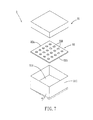
- the converting component 32 is made by the following steps.
- a substrate made of a material such as glass or silicon is deposited with a metal layer by physical vapor deposition (PVD) or chemical vapor deposition (CVD).
- PVD physical vapor deposition
- CVD chemical vapor deposition
- Photolithography technique is then applied to the substrate.
- a photoresist layer made of negative photoresist material is disposed on the metal layer using spin coating or immersion technique.
- Developing and exposing procedures are then applied on the photoresist layer through a photo mask placed thereon to remove an unexposed part of the photoresist layer, thereby exposing a corresponding part of the metal layer.
- the exposed metal layer is removed by etching, followed by stripping the residual photoresist layer to obtain the metal layer with a plurality of holes, each of which has a hole diameter larger then a hole diameter of the orifice 320 of the converting component 32, and will form a respective one of the orifices 320.
- Electroforming technique is then carried out on the metal layer on the substrate, thereby forming an electroforming metal layer with a plurality of through holes.
- the electroforming metal layer is then detached from the substrate along with the metal layer so as to obtain the converting component 32.
- the vapor conduit 4 is made of a material, such as polymer material or stainless steel, that is compatible with the liquid coolant, and has an inner surface formed with a micro structure so as to increase the surface area of the inner surface of the vapor conduit 4, thereby allowing a portion of the coolant vapor to condense thereon.
- the condenser 6 includes a hollow storage chamber 61 and a plurality of hollow fins 62.
- the storage chamber 61 and inner spaces in the fins 62 are fluidly connected, and cooperatively form a condensing chamber 602 to which the fluid inlet 601 and the fluid outlet 603 are connected fluidly.
- the vapor coolant After the vapor coolant enters the condensing chamber 602, heat exchange between the vapor coolant and the inner surface of the condensing chamber 602 occurs, thereby condensing the vapor coolant to liquid form.
- Each of the storage chamber 61 and an inner surface of each of the fins 62 is formed with a micro structure, cooperating with the hollow configuration of the fins 62 to increase the surface area of the condensing chamber 602, thereby yielding higher condensing efficiency.
- the condenser 6 further includes a condenser temperature sensor 63 and a condenser pressure sensor fi4 for monitoring the temperature and pressure of the condensing chamber 602, respectively.
- the power module 7 supplies the power needed to operate the pump 52 and the valve 53, and is connected to the condenser temperature sensor 63 and the condenser pressure sensor 64 of the condenser 6, and the temperature sensor 33 of the cooling module 3.
- the rotational speed of the pump 52 and the flow regulation of the valve 53 are controlled by the power module 7 based on the data from the connected sensors.
- the liquid coolant that enters the coolant chamber 312 is forced to pass through the orifices 320 of the converting component 32, such that the liquid coolant is converted into plumes of micro droplets.
- the liquid coolant droplets then travel toward the interior surface of the thermal-transmittance wall 310, and absorb the heat generated by the heat source 10 and transmitted from the heat source 10 to the interior surface through the exterior surface of the thermal-transmittance wall 310, thereby resulting in formation of the coolant vapor and at least one bubble 9 on the interior surface that stores the coolant vapor.
- the second preferred embodiment of the lamp device 100 has a structure similar to that of the first embodiment.
- the main difference between this embodiment and the previous embodiment resides in the configuration of the casing 31 of the cooling module 3.
- the first casing part 315 has an open side defined by an edge.
- the exterior surface of the thermal-transmittance wall 310 is disposed on an inclined plane.
- the inclined plane forms the angle ( ⁇ ) with a plane of the edge of the open side of the first casing part 315.
- the converting component is disposed at the edge of the open side of the first casing part 315.
- the second preferred embodiment has the same advantages as those of the first preferred embodiment.
Landscapes
- Engineering & Computer Science (AREA)
- General Engineering & Computer Science (AREA)
- Physics & Mathematics (AREA)
- Microelectronics & Electronic Packaging (AREA)
- Optics & Photonics (AREA)
- Cooling Or The Like Of Electrical Apparatus (AREA)
- Arrangement Of Elements, Cooling, Sealing, Or The Like Of Lighting Devices (AREA)
- Non-Portable Lighting Devices Or Systems Thereof (AREA)
- Devices That Are Associated With Refrigeration Equipment (AREA)
- Cooling Or The Like Of Semiconductors Or Solid State Devices (AREA)
Applications Claiming Priority (1)
| Application Number | Priority Date | Filing Date | Title |
|---|---|---|---|
| TW99125345 | 2010-07-30 |
Publications (2)
| Publication Number | Publication Date |
|---|---|
| EP2413030A2 true EP2413030A2 (fr) | 2012-02-01 |
| EP2413030A3 EP2413030A3 (fr) | 2013-06-12 |
Family
ID=44906678
Family Applications (1)
| Application Number | Title | Priority Date | Filing Date |
|---|---|---|---|
| EP11175947.8A Withdrawn EP2413030A3 (fr) | 2010-07-30 | 2011-07-29 | Dispositif de lampe, système de refroidissement et module de refroidissement |
Country Status (4)
| Country | Link |
|---|---|
| US (1) | US8851154B2 (fr) |
| EP (1) | EP2413030A3 (fr) |
| JP (1) | JP2012032146A (fr) |
| TW (1) | TW201204994A (fr) |
Cited By (10)
| Publication number | Priority date | Publication date | Assignee | Title |
|---|---|---|---|---|
| EP2860440A1 (fr) * | 2013-10-09 | 2015-04-15 | Fujikura Ltd. | Dispositif de refroidissement pour un phare de véhicule |
| CN104633570A (zh) * | 2013-11-06 | 2015-05-20 | 现代摩比斯株式会社 | 车灯装置 |
| EP3382268A1 (fr) * | 2017-03-28 | 2018-10-03 | ZKW Group GmbH | Phares de véhicule et système de refroidissement |
| CN108692288A (zh) * | 2017-03-03 | 2018-10-23 | 长城汽车股份有限公司 | 车灯的散热系统 |
| US10239085B2 (en) | 2015-10-30 | 2019-03-26 | Johnson & Johnson Consumer Inc. | Aseptic aerosol misting device |
| AT520677A1 (de) * | 2017-03-28 | 2019-06-15 | Zkw Group Gmbh | Fahrzeugscheinwerfer und Kühlsystem |
| WO2019149536A1 (fr) * | 2018-01-30 | 2019-08-08 | HELLA GmbH & Co. KGaA | Projecteur pour véhicule pourvu d'un dispositif de refroidissement pour un moyen d'éclairage à semi-conducteur |
| US11253885B2 (en) | 2015-10-30 | 2022-02-22 | Johnson & Johnson Consumer Inc. | Aseptic aerosol misting device |
| US11571704B2 (en) | 2015-10-30 | 2023-02-07 | Johnson & Johnson Consumer Inc. | Aseptic aerosol misting device |
| US11583885B2 (en) | 2015-10-30 | 2023-02-21 | Johnson & Johnson Consumer Inc. | Unit dose aseptic aerosol misting device |
Families Citing this family (34)
| Publication number | Priority date | Publication date | Assignee | Title |
|---|---|---|---|---|
| US9854715B2 (en) | 2011-06-27 | 2017-12-26 | Ebullient, Inc. | Flexible two-phase cooling system |
| US9848509B2 (en) | 2011-06-27 | 2017-12-19 | Ebullient, Inc. | Heat sink module |
| US9854714B2 (en) | 2011-06-27 | 2017-12-26 | Ebullient, Inc. | Method of absorbing sensible and latent heat with series-connected heat sinks |
| US9832913B2 (en) | 2011-06-27 | 2017-11-28 | Ebullient, Inc. | Method of operating a cooling apparatus to provide stable two-phase flow |
| US9901013B2 (en) | 2011-06-27 | 2018-02-20 | Ebullient, Inc. | Method of cooling series-connected heat sink modules |
| US9901008B2 (en) | 2014-10-27 | 2018-02-20 | Ebullient, Inc. | Redundant heat sink module |
| JP5938574B2 (ja) * | 2012-04-09 | 2016-06-22 | パナソニックIpマネジメント株式会社 | 冷却装置およびこれを搭載した電気自動車 |
| US10295167B2 (en) * | 2013-04-24 | 2019-05-21 | Xiaodong Xiang | Cooling mechanism for LED light using 3-D phase change heat transfer |
| WO2016021565A1 (fr) * | 2014-08-06 | 2016-02-11 | 富士電機株式会社 | Dispositif semiconducteur |
| TWI575212B (zh) * | 2014-09-24 | 2017-03-21 | 台達電子工業股份有限公司 | 可翻轉使用之液冷散熱裝置及其翻轉配置方法 |
| US9891002B2 (en) | 2014-10-27 | 2018-02-13 | Ebullient, Llc | Heat exchanger with interconnected fluid transfer members |
| US20160120059A1 (en) | 2014-10-27 | 2016-04-28 | Ebullient, Llc | Two-phase cooling system |
| US10184699B2 (en) | 2014-10-27 | 2019-01-22 | Ebullient, Inc. | Fluid distribution unit for two-phase cooling system |
| US20170105313A1 (en) * | 2015-10-10 | 2017-04-13 | Ebullient, Llc | Multi-chamber heat sink module |
| AU2015339811A1 (en) * | 2014-10-27 | 2017-06-15 | Ebullient, Llc | Heat sink module |
| AU2015339759A1 (en) * | 2014-10-27 | 2017-06-15 | Ebullient, Llc | Heat sink for use with pumped coolant |
| US9852963B2 (en) | 2014-10-27 | 2017-12-26 | Ebullient, Inc. | Microprocessor assembly adapted for fluid cooling |
| CZ305708B6 (cs) * | 2014-12-16 | 2016-02-10 | Varroc Lighting Systems, s.r.o. | Světlomet |
| AT518220B1 (de) * | 2016-02-02 | 2017-11-15 | Zkw Group Gmbh | Beleuchtungseinheit für ein Kraftfahrzeug |
| US11581243B2 (en) * | 2016-05-11 | 2023-02-14 | Hypertechnologie Ciara Inc. | CPU cooling system with direct spray cooling |
| KR102553434B1 (ko) * | 2016-07-22 | 2023-07-12 | 제트카베 그룹 게엠베하 | 차량용 램프 |
| US10881019B2 (en) * | 2018-03-09 | 2020-12-29 | Fujitsu Limited | Cooling apparatus |
| KR102523678B1 (ko) * | 2018-06-22 | 2023-04-20 | 현대모비스 주식회사 | 차량용 헤드 램프 |
| US12141508B2 (en) | 2020-03-16 | 2024-11-12 | Washington University | Systems and methods for forming micropillar array |
| DE102020108372A1 (de) * | 2020-03-26 | 2021-09-30 | Heraeus Noblelight Gmbh | Lichtquelle und Verfahren zum Betreiben einer Lichtquelle |
| CN111863740A (zh) * | 2020-04-10 | 2020-10-30 | 上海交通大学 | 用于浸没式液冷系统的自诱导射流无源沸腾散热强化方法及装置 |
| JP7535392B2 (ja) | 2020-06-24 | 2024-08-16 | 川崎重工業株式会社 | 蒸発器及びループ型ヒートパイプ |
| CN113294696B (zh) * | 2021-06-08 | 2022-01-28 | 深圳市昭祺科技有限公司 | 一种散热效果好的led灯珠组件 |
| TWI810059B (zh) * | 2022-09-06 | 2023-07-21 | 劉振亞 | 紅外線燈管散熱自動控制系統 |
| CN115666068B (zh) * | 2022-09-28 | 2025-11-11 | 华为数字能源技术有限公司 | 一种散热装置、功率设备及光伏系统 |
| CN116017950B (zh) * | 2023-01-09 | 2023-10-31 | 深圳市深汕特别合作区虹菱电器有限公司 | 一种led面板会议机 |
| CN118523716B (zh) * | 2024-05-24 | 2024-11-12 | 星河智联(江苏)智造科技有限公司 | 一种双相降温式光伏逆变器 |
| CN119146390B (zh) * | 2024-11-20 | 2025-10-10 | 浙江嘉利(丽水)工业股份有限公司 | 一种基于热量均衡的防雾车灯及散热循环控制系统 |
| CN119815805A (zh) * | 2025-01-21 | 2025-04-11 | 江苏科技大学 | 一种与烧结针肋结构相结合的射流沸腾无泵冷却系统 |
Citations (1)
| Publication number | Priority date | Publication date | Assignee | Title |
|---|---|---|---|---|
| US7082778B2 (en) | 2001-02-22 | 2006-08-01 | Hewlett-Packard Development Company, L.P. | Self-contained spray cooling module |
Family Cites Families (8)
| Publication number | Priority date | Publication date | Assignee | Title |
|---|---|---|---|---|
| JP2995590B2 (ja) * | 1991-06-26 | 1999-12-27 | 株式会社日立製作所 | 半導体冷却装置 |
| JP2913989B2 (ja) * | 1992-03-24 | 1999-06-28 | 株式会社日立製作所 | 電子装置及びそれを用いたコンピュータ |
| JPH05315489A (ja) * | 1992-05-08 | 1993-11-26 | Fuji Electric Co Ltd | 電子機器の液冷式冷却装置 |
| US6205799B1 (en) * | 1999-09-13 | 2001-03-27 | Hewlett-Packard Company | Spray cooling system |
| JP4354151B2 (ja) * | 2002-04-25 | 2009-10-28 | 三菱電機株式会社 | ヒートシンク |
| JP4086582B2 (ja) * | 2002-08-06 | 2008-05-14 | キヤノン株式会社 | 照明装置及び露光装置 |
| FR2911247B1 (fr) * | 2007-01-08 | 2009-02-27 | Sames Technologies Soc Par Act | Carte electronique et plaque froide pour cette carte. |
| US8188595B2 (en) * | 2008-08-13 | 2012-05-29 | Progressive Cooling Solutions, Inc. | Two-phase cooling for light-emitting devices |
-
2011
- 2011-07-27 TW TW100126604A patent/TW201204994A/zh unknown
- 2011-07-29 EP EP11175947.8A patent/EP2413030A3/fr not_active Withdrawn
- 2011-07-29 JP JP2011166942A patent/JP2012032146A/ja active Pending
- 2011-07-29 US US13/193,967 patent/US8851154B2/en not_active Expired - Fee Related
Patent Citations (1)
| Publication number | Priority date | Publication date | Assignee | Title |
|---|---|---|---|---|
| US7082778B2 (en) | 2001-02-22 | 2006-08-01 | Hewlett-Packard Development Company, L.P. | Self-contained spray cooling module |
Cited By (13)
| Publication number | Priority date | Publication date | Assignee | Title |
|---|---|---|---|---|
| EP2860440A1 (fr) * | 2013-10-09 | 2015-04-15 | Fujikura Ltd. | Dispositif de refroidissement pour un phare de véhicule |
| CN104633570A (zh) * | 2013-11-06 | 2015-05-20 | 现代摩比斯株式会社 | 车灯装置 |
| US11583885B2 (en) | 2015-10-30 | 2023-02-21 | Johnson & Johnson Consumer Inc. | Unit dose aseptic aerosol misting device |
| US10239085B2 (en) | 2015-10-30 | 2019-03-26 | Johnson & Johnson Consumer Inc. | Aseptic aerosol misting device |
| US11253885B2 (en) | 2015-10-30 | 2022-02-22 | Johnson & Johnson Consumer Inc. | Aseptic aerosol misting device |
| US12030076B2 (en) | 2015-10-30 | 2024-07-09 | Johnson & Johnson Consumer Inc. | Unit dose aseptic aerosol misting device |
| US11571704B2 (en) | 2015-10-30 | 2023-02-07 | Johnson & Johnson Consumer Inc. | Aseptic aerosol misting device |
| CN108692288A (zh) * | 2017-03-03 | 2018-10-23 | 长城汽车股份有限公司 | 车灯的散热系统 |
| EP3382268A1 (fr) * | 2017-03-28 | 2018-10-03 | ZKW Group GmbH | Phares de véhicule et système de refroidissement |
| AT520677A1 (de) * | 2017-03-28 | 2019-06-15 | Zkw Group Gmbh | Fahrzeugscheinwerfer und Kühlsystem |
| AT520677B1 (de) * | 2017-03-28 | 2019-09-15 | Zkw Group Gmbh | Fahrzeugscheinwerfer und Kühlsystem |
| WO2019149536A1 (fr) * | 2018-01-30 | 2019-08-08 | HELLA GmbH & Co. KGaA | Projecteur pour véhicule pourvu d'un dispositif de refroidissement pour un moyen d'éclairage à semi-conducteur |
| US11268674B2 (en) | 2018-01-30 | 2022-03-08 | HELLA GmbH & Co. KGaA | Headlight for a vehicle with a cooling device for a semiconductor illuminant |
Also Published As
| Publication number | Publication date |
|---|---|
| JP2012032146A (ja) | 2012-02-16 |
| US8851154B2 (en) | 2014-10-07 |
| EP2413030A3 (fr) | 2013-06-12 |
| US20120026745A1 (en) | 2012-02-02 |
| TW201204994A (en) | 2012-02-01 |
Similar Documents
| Publication | Publication Date | Title |
|---|---|---|
| US8851154B2 (en) | Cooling module and system for lamp device | |
| US20110277491A1 (en) | Heat dissipation system with a spray cooling device | |
| JP3196017U (ja) | 相変化放熱装置及び相変化放熱システム | |
| US9685393B2 (en) | Phase-change chamber with patterned regions of high and low affinity to a phase-change medium for electronic device cooling | |
| US6981543B2 (en) | Modular capillary pumped loop cooling system | |
| US6708515B2 (en) | Passive spray coolant pump | |
| CN102157467A (zh) | 冷却散热系统及其冷却装置 | |
| TWI251658B (en) | Ultrasonic atomizing cooling apparatus | |
| US6952346B2 (en) | Etched open microchannel spray cooling | |
| US20070133173A1 (en) | Compact spray cooling module | |
| WO2008025161A1 (fr) | Ensemble caloduc à plusieurs éléments photoémetteurs | |
| US7549298B2 (en) | Spray cooling with spray deflection | |
| US20070284090A1 (en) | Loop type heat dissipating apparatus with sprayer | |
| CN103096687A (zh) | 气液循环散热装置 | |
| US10349556B2 (en) | Cooling device and electronic device using same | |
| Joshi et al. | Keynote Lecture: Micro and Meso Scale Compact Heat Exchangers in Electronics Thermal Management–Review | |
| TWM472875U (zh) | 相變化散熱裝置 | |
| JP2021032539A (ja) | 熱輸送プレートおよび熱輸送プレートの製造方法 | |
| US20070163756A1 (en) | Closed-loop latent heat cooling method and capillary force or non-nozzle module thereof | |
| KR101574084B1 (ko) | 광 반도체 조명장치 | |
| JP6197522B2 (ja) | ループヒートパイプ | |
| CN103292291A (zh) | 散热装置与具有此散热装置的发光二极管led灯具 | |
| CN110319626A (zh) | 冷却装置 | |
| JP2006084073A (ja) | 減圧気化冷却装置 | |
| TWM437482U (en) | Heat dissipation system, heat dissipation system for vehicle and assembly of vehicle light and heat dissipation system |
Legal Events
| Date | Code | Title | Description |
|---|---|---|---|
| AK | Designated contracting states |
Kind code of ref document: A2 Designated state(s): AL AT BE BG CH CY CZ DE DK EE ES FI FR GB GR HR HU IE IS IT LI LT LU LV MC MK MT NL NO PL PT RO RS SE SI SK SM TR |
|
| AX | Request for extension of the european patent |
Extension state: BA ME |
|
| PUAI | Public reference made under article 153(3) epc to a published international application that has entered the european phase |
Free format text: ORIGINAL CODE: 0009012 |
|
| RIN1 | Information on inventor provided before grant (corrected) |
Inventor name: MENG, HSIEN Inventor name: MENG, HSIEN- CHUN Inventor name: WU, CHUN-HSIEN Inventor name: LIAO, CHIA- CHEN Inventor name: CHENG, KAI-AN |
|
| RTI1 | Title (correction) |
Free format text: LAMP DEVICE, COOLING SYSTEM AND COOLING MODULE |
|
| PUAL | Search report despatched |
Free format text: ORIGINAL CODE: 0009013 |
|
| AK | Designated contracting states |
Kind code of ref document: A3 Designated state(s): AL AT BE BG CH CY CZ DE DK EE ES FI FR GB GR HR HU IE IS IT LI LT LU LV MC MK MT NL NO PL PT RO RS SE SI SK SM TR |
|
| AX | Request for extension of the european patent |
Extension state: BA ME |
|
| RIC1 | Information provided on ipc code assigned before grant |
Ipc: F21V 29/00 20060101AFI20130503BHEP |
|
| STAA | Information on the status of an ep patent application or granted ep patent |
Free format text: STATUS: THE APPLICATION IS DEEMED TO BE WITHDRAWN |
|
| 18D | Application deemed to be withdrawn |
Effective date: 20131213 |