EP2420910B1 - Druckregelgehäuseanordnung - Google Patents
Druckregelgehäuseanordnung Download PDFInfo
- Publication number
- EP2420910B1 EP2420910B1 EP11158324.1A EP11158324A EP2420910B1 EP 2420910 B1 EP2420910 B1 EP 2420910B1 EP 11158324 A EP11158324 A EP 11158324A EP 2420910 B1 EP2420910 B1 EP 2420910B1
- Authority
- EP
- European Patent Office
- Prior art keywords
- housing
- edge
- assembly
- diaphragm
- pressure regulator
- Prior art date
- Legal status (The legal status is an assumption and is not a legal conclusion. Google has not performed a legal analysis and makes no representation as to the accuracy of the status listed.)
- Active
Links
Images


Classifications
-
- G—PHYSICS
- G05—CONTROLLING; REGULATING
- G05D—SYSTEMS FOR CONTROLLING OR REGULATING NON-ELECTRIC VARIABLES
- G05D16/00—Control of fluid pressure
- G05D16/04—Control of fluid pressure without auxiliary power
- G05D16/06—Control of fluid pressure without auxiliary power the sensing element being a flexible membrane, yielding to pressure, e.g. diaphragm, bellows, capsule
- G05D16/063—Control of fluid pressure without auxiliary power the sensing element being a flexible membrane, yielding to pressure, e.g. diaphragm, bellows, capsule the sensing element being a membrane
- G05D16/0644—Control of fluid pressure without auxiliary power the sensing element being a flexible membrane, yielding to pressure, e.g. diaphragm, bellows, capsule the sensing element being a membrane the membrane acting directly on the obturator
- G05D16/0655—Control of fluid pressure without auxiliary power the sensing element being a flexible membrane, yielding to pressure, e.g. diaphragm, bellows, capsule the sensing element being a membrane the membrane acting directly on the obturator using one spring-loaded membrane
-
- Y—GENERAL TAGGING OF NEW TECHNOLOGICAL DEVELOPMENTS; GENERAL TAGGING OF CROSS-SECTIONAL TECHNOLOGIES SPANNING OVER SEVERAL SECTIONS OF THE IPC; TECHNICAL SUBJECTS COVERED BY FORMER USPC CROSS-REFERENCE ART COLLECTIONS [XRACs] AND DIGESTS
- Y10—TECHNICAL SUBJECTS COVERED BY FORMER USPC
- Y10T—TECHNICAL SUBJECTS COVERED BY FORMER US CLASSIFICATION
- Y10T137/00—Fluid handling
- Y10T137/598—With repair, tapping, assembly, or disassembly means
- Y10T137/599—Pressure regulating type valve
- Y10T137/5994—Diaphragm type
-
- Y—GENERAL TAGGING OF NEW TECHNOLOGICAL DEVELOPMENTS; GENERAL TAGGING OF CROSS-SECTIONAL TECHNOLOGIES SPANNING OVER SEVERAL SECTIONS OF THE IPC; TECHNICAL SUBJECTS COVERED BY FORMER USPC CROSS-REFERENCE ART COLLECTIONS [XRACs] AND DIGESTS
- Y10—TECHNICAL SUBJECTS COVERED BY FORMER USPC
- Y10T—TECHNICAL SUBJECTS COVERED BY FORMER US CLASSIFICATION
- Y10T137/00—Fluid handling
- Y10T137/7722—Line condition change responsive valves
- Y10T137/7781—With separate connected fluid reactor surface
- Y10T137/7793—With opening bias [e.g., pressure regulator]
- Y10T137/7808—Apertured reactor surface surrounds flow line
-
- Y—GENERAL TAGGING OF NEW TECHNOLOGICAL DEVELOPMENTS; GENERAL TAGGING OF CROSS-SECTIONAL TECHNOLOGIES SPANNING OVER SEVERAL SECTIONS OF THE IPC; TECHNICAL SUBJECTS COVERED BY FORMER USPC CROSS-REFERENCE ART COLLECTIONS [XRACs] AND DIGESTS
- Y10—TECHNICAL SUBJECTS COVERED BY FORMER USPC
- Y10T—TECHNICAL SUBJECTS COVERED BY FORMER US CLASSIFICATION
- Y10T137/00—Fluid handling
- Y10T137/7722—Line condition change responsive valves
- Y10T137/7781—With separate connected fluid reactor surface
- Y10T137/7793—With opening bias [e.g., pressure regulator]
- Y10T137/7809—Reactor surface separated by apertured partition
- Y10T137/781—In valve stem
- Y10T137/7811—Also through reactor surface
Definitions
- This invention relates to valves and pressure regulators generally, and specifically, to a housing assembly for axial-flow fluid pressure regulators particularly suited for use in agricultural irrigation systems.
- pressure regulators in irrigation systems in order to provide substantially constant, regulated outlet pressure over a wide range of regulator inlet pressures, to thereby insure, for example, that a supply of water to a sprinkler or other irrigation device is maintained at a substantially uniform pressure.
- the need for such regulators is particularly acute in low pressure systems because even slight variations in pressure may cause much greater variations in water delivery than the same system operating at high pressure.
- the assignee of this invention currently manufactures and sells fluid pressure regulators of the flow-through type, having an inlet at one end of a tubular housing and an outlet at the other end of the tubular housing.
- a valve or regulator seat is fixed within the housing and is adapted to be engaged by a tubular plunger which is spring-biased away from the seat (i.e., in the direction of fluid flow) so that under normal conditions, maximum flow through the regulator is permitted.
- the plunger In the event of a pressure surge, the plunger is moved by back pressure within a diaphragm chamber, against the action of an opposed coil spring (and against atmospheric pressure), toward the regulator seat to thereby decrease flow through the regulator until the pressure is reduced, at which point the plunger will stop or, if pressure decreases sufficiently, move upwardly away from the seat to thereby increase the flow. In this way, the regulator constantly seeks an equilibrium position to thereby maintain a substantially uniform outlet pressure. See, for example, U.S. Patent Nos. 7,048,001 ; 5,875,815 ; and 5,257,646 .
- the internal diaphragm is engaged and held in place by a cap (or components within the cap) or upper housing that is fastened to the housing body or lower housing.
- the cap is secured to the housing body (or lower housing) by four circumferentially-arranged screws. This method of fastening is advantageous in that the cap does not rotate relative to the housing during assembly, and thus, the exposed diaphragm edge is not disturbed.
- assembly equipment designed to simultaneously apply and tighten plural screws is expensive and complex.
- a pressure regulator housing coupling arrangement that is of relatively simple design which facilitates the assembly process without damaging the otherwise fragile regulator diaphragm.
- any reference herein to "upper”, “lower”, “vertical” or “horizontal” edges or other surfaces of the regulator cap and/or housing is made with respect to the orientation of the regulator as shown in Fig. 1 , and is not intended to be limiting in any way, recognizing that the installed orientation of the regulator may be different from that shown in Fig 1 .
- the invention relates to a pressure regulator housing and internal stem and diaphragm assembly that eliminate the need for screws or other discrete fasteners in favor of a rotating bayonet-type attachment to secure the cap to the housing.
- the diaphragm edge is supported in such a way that it rotates with the regulator cap on assembly, so that there is no relative rotation between the cap and the diaphragm, and no contact between the diaphragm and the housing, thus eliminating any concern for damage to the diaphragm during assembly.
- an internal regulator plunger or stem has an upper radial flange which supports a radially inner edge of the diaphragm, clamped between an annular, inner clamp ring and the flange.
- An annular outer clamp ring is adapted to be received over the plunger and engage the outer edge of the diaphragm.
- the outer clamp ring is formed with a plurality of relatively closely-spaced teeth projecting radially outwardly from its peripheral edge.
- An internal wall portion of the cap is formed with a plurality (six in the illustrated example) of relatively widely circumferentially spaced teeth or lugs that project radially inwardly, so that when the outer clamp ring is located over the outer edge of the diaphragm, the teeth on the internal cap wall will naturally "find” and engage selected ones of the teeth on the outer clamp ring.
- the diaphragm edge sandwiched between an internal radially-oriented, annular surface of the cap and the outer clamp ring, the diaphragm is fixed relative to the cap so that on assembly, the diaphragm will rotate with the cap.
- the upper edge of the housing will engage a smooth underside of the outer clamp ring, such that no part of the diaphragm is engaged by the housing. In this way, no torque or twisting force is applied to the diaphragm during assembly of the cap to the housing.
- the cap or upper housing and the regulator body or lower housing are formed with cooperating surface features that enable a bayonet-type attachment where the cap is axially-aligned with and telescoped over the upper edge of the housing, and then rotated into locking engagement.
- the lower skirt portion of the cap is formed to include on its interior peripheral surface a plurality of circumferentially-spaced locking pads.
- the locking pads are substantially square in shape with a relatively sharp edge on one vertical side thereof, and a sloped or ramped edge on the opposite vertical side thereof The locking pads are flush with the lower edge of the cap skirt, and are generally axially-aligned with the lugs formed on the interior of the cap, although they need not be so aligned.
- the outer peripheral surface of the housing at the upper edge thereof is formed with a plurality of circumferentially-spaced cam platforms, each defined by a cam surface that increases in diameter along a generally arcuate surface extending from a relatively flat base portion to a sharp axial alignment edge.
- a lower portion of the cam surface for each cam platform is cut out to form a locking recess, located proximate the sharp alignment edge, the locking recess sized and shaped to receive a corresponding locking pad on the inside of the cap as described above.
- the circumferential space between the edge of the locking recess and the sharp alignment edge associated with that cam surface is taken up by a relatively small, axially-extending, rib that has an axially-oriented ramped surface on one side, along the locking recess and a sharp vertical edge on its other side, in alignment with, and becoming part of the sharp alignment edge.
- the ramped surface on the rib may be included to permit an "over-ride" of the locked arrangement as described further herein.
- the cap When the cap and housing are ready for assembly, with the plunger, diaphragm and outer clamp ring properly located, the cap may be telescoped over the housing when the sharp edges of the locking pads are substantially aligned with (but slightly offset from) the sharp alignment edges of the plural cam platforms.
- the cap Upon full insertion of the housing upper end into the cap, the cap may be rotated such that the locking pads ride over the cam surfaces of the cam platforms and snap or click into the corresponding locking recesses, with the sharp edges of the respective locking pads and locking recesses preventing any back-rotation of the cap.
- the engagement of upper horizontal edges on the locking pads with upper horizontal edges of the locking recesses prevents relative axial movement between the cap and the housing.
- the invention provides a pressure regulator housing assembly comprising a lower housing and an upper housing adapted for assembly via axial engagement and relative rotation; a plunger and diaphragm assembly supported within the lower and upper housings, the plunger movable toward and away from a valve seat, and the diaphragm having a radially inner edge fixed to one end of the plunger and a radially outer edge clamped between an annular surface within the upper housing and a surface of a clamp ring; wherein an outer peripheral surface of the clamp ring is formed with a first plurality of vertically-oriented, tapered teeth and an inner peripheral wall portion of the upper housing adjacent the annular surface is formed with a second plurality of vertically-oriented teeth engageable, on assembly, with the first plurality of vertically-oriented teeth thereby locking the clamp ring against rotation relative to the upper housing; and further wherein an inner peripheral surface of the upper housing is formed with circumferentially-spaced locking pads and an outer peripheral surface of the lower housing is formed with circum
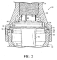
- a fluid pressure regulator housing assembly 10 in accordance with an exemplary but nonlimiting embodiment includes a hollow lower housing 12 and a hollow upper housing or cap 14. Both housing and cap components are internally threaded at their respective inlet and outlet ends, 16, 18, permitting the regulator to be secured in-line between, for example, a sprinkler at the outlet end and a supply hose at the inlet end.
- the interior of the cap is counterbored to form a series of at least the annular shoulders 20, 22 and 24, the purposes for which will be described further herein. It is noted initially that the shoulder 20 defines an internal diameter section 26 of the cap, adjacent the internal threads at the cap outlet 18, which receives the upper end 28 of a plunger-diaphragm assembly 30.
- the plunger-diaphragm assembly 30 includes a tubular plunger 32 having a tapered lower edge 34 ( Figs. 1 and 4 ) forming a valve for interaction with a valve seat (not shown) supported in the housing 12.
- the plunger 32 is provided adjacent the upper or outlet end 28 thereof (flow is from bottom to top as viewed in Fig. 1 ) with a radial flange 36 ( Figs. 1 and 4 ).
- a radially inner edge 38 of an annular "rolling" diaphragm 40 is supported on the flange 36 and is clamped between the flange and a rigid inner clamp ring 42 ( Figs. 1 and 2 ) snap-fit over an array of upstanding spring fingers 44 that extend upwardly from the flange 36, as best appreciated from Fig. 1 .
- the inner clamp ring 42 is adapted to engage the shoulder 22 of the cap when the plunger 32 is in its fully raised position as shown in Figs. 1 and 2 .
- the intermediate portion of the diaphragm assumes a substantial U-shape ( Fig. 1 ) when the plunger 32 is in the raised position, and the radially outer edge 62 of the diaphragm 40 is held between shoulder 24 of the cap and an outer clamp ring 48 described further below.
- the plunger 32 moves up and down within a limited range of movement as a function of outlet pressure (i:e., the pressure at the outlet end 18), noting that the inner clamp ring 42 and flange 36 are located in a diaphragm chamber 50 ( Fig. 2 ) which is exposed to outlet pressure due to the presence of radial slots or grooves 52 ( Fig. 2 ) formed in the shoulder 22 that connect to the diaphragm chamber 50.
- outlet pressure is high, the pressure in the diaphragm chamber 50 causes the plunger 32 including the tapered lower edge or valve 34 to move downwardly toward the valve seat to restrict flow.
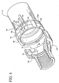
- the outer clamp ring 48 is formed with an upper flanged portion 54 having a plurality of axially-extending, upwardly tapered teeth 56 formed on the outer peripheral edge thereof.
- the teeth 56 taper in an upward direction for a purpose described further below.
- An inner skirt portion 58 extends downwardly from the upper flanged portion and is sized to help locate and center the outer clamp ring 48 ring within the upper end of the housing 12 on assembly.
- the upward-facing edge 60 of the flanged portion 54 is grooved at 61 ( Figs. 1 and 2 ) to receive an increased thickness of the diaphragm outer edge 62, thus facilitating the retention function of the outer clamp ring 48.
- an inner surface 64 of the cap 14, adjacent the shoulder 24, is provided with a first plurality (six in the illustrated example) of circumferentially-spaced teeth or lugs 66 that project radially inwardly and that are adapted to engage between respective pairs of the teeth 56 on the outer clamp ring 48.
- the outer clamp ring 48 when the housing 12 is moved axially into telescoped engagement with the cap 14 as described in greater detail below, the outer clamp ring 48 will orient itself with certain of the teeth 56 engaged with the lugs 66 on the cap inner wall, thus preventing any relative rotation between the outer clamp ring 48 and the cap 14. This meshing engagement is facilitated by the upward taper of the teeth 56. Now, when so located, the outer clamp ring 48 will also seat on the outer peripheral edge 62 of the diaphragm 40 with the thickened diaphragm edge engaged in the groove formed in the upward-facing edge 60.
- the outer peripheral edge 62 of the diaphragm 40 is clamped between the shoulder 24 and the outer clamp ring 48, and both the outer clamp ring 48 and diaphragm 40 are prevented from relative rotation with respect to the cap 14.
- the smooth annular surface 68 on the underside of the outer clamp ring 48 that is engaged by the upper edge 70 of the housing (best seen in Fig. 2 ) i.e., no part of the diaphragm 40 is exposed to any contact with the housing 12 that, during the locking rotation described below, would otherwise cause torque or twisting action to be applied to the outer edge 62 of the diaphragm.
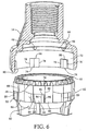
- the cap 14 and the housing 12 are formed with cooperating surface features that enable a bayonet-type attachment where the cap 14 is axially-aligned with, and telescoped over, the upper end of the housing 12, and then rotated into locking engagement. More specifically, in the illustrated, nonlimiting embodiment, a lower skirt portion 72 of the cap 14 is formed to include on its interior surface a plurality of circumferentially-spaced and radially-inwardly projecting locking pads 74 (best seen in Figs. 6 and 8 ).
- the locking pads 74 are substantially square in shape with a relatively sharp edge 76 on one vertical side thereof, and a sloped or ramped edge 78 on the opposite vertical side thereof
- the locking pads 74 are flush with a lower edge 80 of the cap ( Fig. 6 ), and are generally axially-aligned with the lugs 66, although they need not be so aligned.
- the outer surface of the housing 12 at the upper end thereof is formed with a plurality of circumferentially-spaced cam platforms 82 ( Figs. 6 , 7 and 8 ), each defined by a cam surface 84 that increases in diameter along a generally arcuate surface extending from a relatively flat base portion 86 to a sharp axial alignment edge 88.
- cam platforms are replicated about the circumference of the upper end of the housing 12, thus forming a series of circumferentially-spaced, vertically-extending alignment edges 88.
- a lower portion of the cam surface 84 for each ratchet tooth is cut out to form a locking recess 90, located proximate the sharp alignment edge 88, the locking recess 90 sized and shaped to receive a corresponding locking pad 74 on the inside of the cap 14 as described above.
- the circumferential space between the edge of the locking recess 90 and the sharp alignment edge 88 associated with that cam surface is taken up by a relatively small, axially-extending, rib 92 that may have an axially-oriented ramped surface 94 on one side, along the locking recess, and a sharp vertical edge 96 on its other side, in alignment with, and becoming part of the sharp alignment edge 88.
- the ramped surface 94 on the rib may be included to permit an "over-ride" of the locked arrangement as described further herein.
- the cap 14 When the cap 14 and housing 12 are ready for assembly, with the plunger-diaphragm assembly 30 and outer clamp ring 48 properly located, the cap 14 may be telescoped over the housing 12 when the sharp edges 76 of the locking pads 74 are substantially aligned with (but slightly offset from) the sharp alignment edges 88.
- the cap may be inverted from the orientation shown in Fig. 1 to facilitate placement of the plunger-diaphragm assembly 30 into the cap.
- the outer clamp ring 48 can then be located over the outer edge of the diaphragm, with meshing engagement of teeth 56 and lugs 66, followed by insertion of the housing into the cap.
- the outer clamp ring 48 can be seated in the housing, relying on the friction fit between the clamp ring skirt portion 58 and the interior surface of the housing to hold the clamp ring 48 as the cap and housing are brought together.
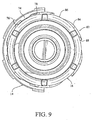
- the cap 14 may be rotated such that the locking pads 74 ride over the cam surfaces 84 of the cam platforms 82 and snap or click into the corresponding locking recesses 90, with the sharp edges 76, 89 of the locking pads 74 and locking recesses 90, respectively, preventing any back-rotation of the cap 14 (see Fig. 10 ).
- the engagement of upper horizontal edges 98 on the locking pads 74 with upper horizontal edges 100 of the locking recesses 90 prevents any further relative axial movement between the cap and the housing.
- the ramped surfaces 94 are employed, it is possible to exert a further rotation force on the cap to move the locking pads out of the locking recesses 90 to enable disassembly of the cap from the housing.
- the ramped surface 94 can be eliminated in favor of a sharp edge like the alignment edge 88. With two sharp edges defining the opposite axial sides of the locking recesses 90, further relative rotation between the cap and the housing is essentially precluded.
Landscapes
- Physics & Mathematics (AREA)
- Fluid Mechanics (AREA)
- General Physics & Mathematics (AREA)
- Engineering & Computer Science (AREA)
- Automation & Control Theory (AREA)
- Control Of Fluid Pressure (AREA)
Claims (9)
- Druckregelgehäuseanordnung, umfassend:ein unteres Gehäuse (12) und ein oberes Gehäuse (14), die zum Zusammenbau über axialen Eingriff und relative Rotation ausgelegt sind;eine Kolben-und-Diaphragma-Anordnung (30), die innerhalb des unteren und oberen Gehäuses gestützt wird, wobei der Kolben in Richtung zu und weg von einem Ventilsitz beweglich ist und das Diaphragma einen radial inneren Rand (38), der an einem Ende des Kolbens befestigt ist, und einen radial äußeren Rand (62), der zwischen einer ringförmigen Fläche innerhalb des oberen Gehäuses und einer Oberfläche einer Ringklemme (48) eingeklemmt ist, aufweist;wobei eine äußere Umfangsfläche der Ringklemme mit einer ersten Vielzahl von vertikal orientierten spitz zulaufenden Zähnen (56) ausgebildet ist, und ein innerer Umfangswandteil der ringförmigen, dem oberen Gehäuse gegenüberliegenden Oberfläche mit einer zweiten Vielzahl von vertikal orientierten eingreifbaren Zähnen (66) ausgebildet ist, wodurch die Ringklemme, beim Zusammenbau, mit der ersten Vielzahl von vertikal orientierten Zähnen gegen Rotation relativ zu dem oberen Gehäuse arretiert ist; undwobei weiterhin eine innere Umfangsfläche des oberen Gehäuses mit zirkumferentiell beabstandeten Arretierkissen (74) ausgebildet ist, und eine äußere Umfangsfläche des unteres Gehäuses mit zirkumferentiell beabstandeten Arretieraussparungen (60) ausgebildet ist, die, beim axialen Zusammenbau des oberen Gehäuses über die unteren Gehäuse von den zirkumferentiell beabstandeten Arretierkissen versetzt sind, und die bei relativer Rotation zwischen dem oberen und unteren Gehäuse in die zirkumferentiell beabstandeten Arretieraussparungen eingesetzt werden, um dadurch das obere Gehäuse an dem unteren Gehäuse zu arretieren, und wobei während der relativen Rotation das Diaphragma mit dem oberen Gehäuse rotiert und ein oberer Rand (70) des unteren Gehäuses durch eine untere Fläche (68) der Ringklemme gegriffen wird.
- Druckregelgehäuseanordnung nach Anspruch 1, wobei die Ringklemme (48) eine obere Fläche (60) aufweist, die mit einer ringförmigen Nut (61) zum Aufnehmen des radial äußeren Rand (62) des Diaphragmas ausgebildet ist.
- Druckregelgehäuseanordnung nach Anspruch 1, wobei die erste Vielzahl von vertikal orientierten Zähnen (56) relativ eng beabstandet ist, und die zweite Vielzahl von vertikal orientierten Zähnen (66) relativ weit beabstandet ist.
- Druckregelgehäuseanordnung nach Anspruch 1, wobei die erste und die zweite Vielzahl von Zähnen (56, 66) in entgegengesetzte Richtungen spitz zulaufend sind, um den Eingriff zu erleichtern.
- Druckregelgehäuseanordnung nach Anspruch 1, wobei die Arretieraussparungen (90) konfiguriert sind, um relative Achs- und Rotationsbewegung zwischen dem oberen (14) und unteren (12) Gehäuse zu verhindern, wenn die Arretierkissen (74) in die Arretieraussparungen eingesetzt sind.
- Druckregelgehäuseanordnung nach Anspruch 1, wobei die Arretierkissen (74) im Wesentlichen rechteckig sind, mit einem relativ scharfen Rand (76) auf einer vertikalen Seite davon und einem ansteigenden Rand (78) auf einer entgegengesetzten vertikalen Seite davon.
- Druckregelgehäuseanordnung nach Anspruch 6, wobei die äußere Umfangsfläche des unteren Gehäuses (12) mit einer Vielzahl von zirkumferentiell beabstandeten Nockenplatten (82) ausgebildet ist, die jeweils definiert sind durch eine Nockenfläche (84), die im Durchmesser entlang einer allgemein bogenförmigen Fläche zunimmt, die sich von einem relativ flachen Basisteil (86) zu einer relativ scharfen axialen Ausrichtungskante (88) erstreckt, einen unteren Teil der Nockenfläche vor jeder Nockenplatte, der ausgeschnitten ist, um eine der zirkumferentiell beabstandeten proximal zu der relativ scharfen Ausrichtungskante angeordnet Arretieraussparungen (90) zu bilden.
- Druckregelgehäuseanordnung nach Anspruch 7, wobei ein Raum zwischen einem Rand der Arretieraussparung (90) und der relativ scharfen Ausrichtungskante (88) von einem sich axial erstreckenden Steg (92) mit einer axial orientierten ansteigenden Fläche (94) auf einer vertikalen Seite davon aufgenommen wird.
- Druckregelgehäuseanordnung nach Anspruch 8, wobei die relativ scharfe Ausrichtungskante (88) eine gegenüberliegende Seite des sich axial erstreckenden Stegs (92) aufweist.
Applications Claiming Priority (1)
| Application Number | Priority Date | Filing Date | Title |
|---|---|---|---|
| US31445010P | 2010-03-16 | 2010-03-16 |
Publications (3)
| Publication Number | Publication Date |
|---|---|
| EP2420910A2 EP2420910A2 (de) | 2012-02-22 |
| EP2420910A3 EP2420910A3 (de) | 2015-05-27 |
| EP2420910B1 true EP2420910B1 (de) | 2016-04-27 |
Family
ID=44646253
Family Applications (1)
| Application Number | Title | Priority Date | Filing Date |
|---|---|---|---|
| EP11158324.1A Active EP2420910B1 (de) | 2010-03-16 | 2011-03-15 | Druckregelgehäuseanordnung |
Country Status (4)
| Country | Link |
|---|---|
| US (1) | US8714186B2 (de) |
| EP (1) | EP2420910B1 (de) |
| AU (1) | AU2011201174B2 (de) |
| ES (1) | ES2571107T3 (de) |
Families Citing this family (5)
| Publication number | Priority date | Publication date | Assignee | Title |
|---|---|---|---|---|
| US11933417B2 (en) | 2019-09-27 | 2024-03-19 | Rain Bird Corporation | Irrigation sprinkler service valve |
| EP4172524A1 (de) | 2020-06-24 | 2023-05-03 | Winston Products LLC | Ausdehnbarer schlauch |
| US12030072B2 (en) | 2020-11-16 | 2024-07-09 | Rain Bird Corporation | Pressure regulation device and method for irrigation sprinklers |
| US11717838B2 (en) * | 2021-05-18 | 2023-08-08 | Komet Austria Gmbh | Pressure regulator for a liquid |
| WO2023102172A1 (en) * | 2021-12-04 | 2023-06-08 | Winston Products Llc | Expandable hose |
Family Cites Families (17)
| Publication number | Priority date | Publication date | Assignee | Title |
|---|---|---|---|---|
| US3865137A (en) * | 1972-05-26 | 1975-02-11 | Bernz O Matic Corp | Regulator valve |
| US4692565B1 (en) | 1986-02-06 | 1995-09-12 | Raychem Corp | Segmented end seal and closure |
| GB2197409B (en) * | 1986-10-31 | 1990-08-22 | Kitz Corp | Pipe joint |
| US5118120A (en) | 1989-07-10 | 1992-06-02 | General Electric Company | Leaf seals |
| US5257646A (en) | 1992-08-17 | 1993-11-02 | Nelson Irrigation Corporation | O-ring damped regulator |
| GB2282248B (en) * | 1993-09-27 | 1997-10-15 | Advanced Risc Mach Ltd | Data memory |
| US5724816A (en) | 1996-04-10 | 1998-03-10 | General Electric Company | Combustor for a gas turbine with cooling structure |
| US5881757A (en) * | 1997-05-02 | 1999-03-16 | Senninger Irrigation, Inc. | Pressure regulator apparatus and method |
| US5875815A (en) | 1997-10-20 | 1999-03-02 | Nelson Irrigation Corporation | Combination pressure regulator/drain check valve |
| US6164656A (en) | 1999-01-29 | 2000-12-26 | General Electric Company | Turbine nozzle interface seal and methods |
| JP3502561B2 (ja) * | 1999-02-22 | 2004-03-02 | Smc株式会社 | レギュレーター |
| US6334310B1 (en) | 2000-06-02 | 2002-01-01 | General Electric Company | Fracture resistant support structure for a hula seal in a turbine combustor and related method |
| US6427446B1 (en) | 2000-09-19 | 2002-08-06 | Power Systems Mfg., Llc | Low NOx emission combustion liner with circumferentially angled film cooling holes |
| US7048001B2 (en) | 2004-04-13 | 2006-05-23 | Nelson Irrigation Corporation | Pressure regulator with single strut regulator seat |
| US7168444B2 (en) | 2004-06-01 | 2007-01-30 | Nelson Irrigation Corporation | Flow through pressure regulator with pinch valve |
| DE102004059858A1 (de) | 2004-12-11 | 2006-06-29 | Alstom Technology Ltd | Lamellendichtung, insbesondere für eine Gasturbine |
| US7401622B2 (en) | 2006-06-09 | 2008-07-22 | Nelson Irrigation Corporation | Modular pressure regulator |
-
2011
- 2011-03-15 US US13/047,946 patent/US8714186B2/en active Active
- 2011-03-15 EP EP11158324.1A patent/EP2420910B1/de active Active
- 2011-03-15 ES ES11158324T patent/ES2571107T3/es active Active
- 2011-03-16 AU AU2011201174A patent/AU2011201174B2/en not_active Ceased
Also Published As
| Publication number | Publication date |
|---|---|
| AU2011201174B2 (en) | 2014-10-09 |
| EP2420910A3 (de) | 2015-05-27 |
| AU2011201174A1 (en) | 2011-10-06 |
| EP2420910A2 (de) | 2012-02-22 |
| US20110226347A1 (en) | 2011-09-22 |
| US8714186B2 (en) | 2014-05-06 |
| ES2571107T3 (es) | 2016-05-24 |
Similar Documents
| Publication | Publication Date | Title |
|---|---|---|
| EP2420910B1 (de) | Druckregelgehäuseanordnung | |
| US20240024717A1 (en) | Fire protection sprinkler assembly | |
| AU745573B2 (en) | Combination pressure regulator/drain check valve | |
| US20240218948A1 (en) | Pre-assembled coupling assembly with cap | |
| US20120227838A1 (en) | Pressure regulator with manual shut-off valve | |
| CN106061576B (zh) | 过滤器组 | |
| JP6258315B2 (ja) | ボルト式弁制御要素 | |
| US10786767B2 (en) | Filter apparatus with torque limiting mechanism | |
| CA2124524C (en) | Attachment for thermal probe | |
| CA2898716C (en) | Bracket for showerhead with integral flow control | |
| US5743291A (en) | Sanitary safety device | |
| US5967181A (en) | Pressure regulator for watering system | |
| EP2252812B1 (de) | Gleitringdichtungsanordung, montageverfahren und montagevorrichtung | |
| KR101821656B1 (ko) | 체결 조립체 | |
| AU2016368382A1 (en) | Stopper with integrated pressure equalizing device | |
| US10352491B2 (en) | Anti-rotation device for hydraulic connectors | |
| EP1938880A1 (de) | Verwendung nicht metallischer Ladegeräte in Flüssigfiltern | |
| CN109715961B (zh) | 公差补偿元件 | |
| US8640733B1 (en) | Excess flow cartridge | |
| JP7365236B2 (ja) | フィルタシステム | |
| CA2537838A1 (en) | Check valve | |
| WO2000039489A1 (en) | Air flow control valve | |
| US20140097374A1 (en) | Excess flow valve with flexible diaphragm member | |
| US9550485B2 (en) | Plug retention system for a brake actuator | |
| CN114658904B (zh) | 一种燃气稳压阀 |
Legal Events
| Date | Code | Title | Description |
|---|---|---|---|
| AK | Designated contracting states |
Kind code of ref document: A2 Designated state(s): AL AT BE BG CH CY CZ DE DK EE ES FI FR GB GR HR HU IE IS IT LI LT LU LV MC MK MT NL NO PL PT RO RS SE SI SK SM TR |
|
| AX | Request for extension of the european patent |
Extension state: BA ME |
|
| PUAI | Public reference made under article 153(3) epc to a published international application that has entered the european phase |
Free format text: ORIGINAL CODE: 0009012 |
|
| PUAL | Search report despatched |
Free format text: ORIGINAL CODE: 0009013 |
|
| AK | Designated contracting states |
Kind code of ref document: A3 Designated state(s): AL AT BE BG CH CY CZ DE DK EE ES FI FR GB GR HR HU IE IS IT LI LT LU LV MC MK MT NL NO PL PT RO RS SE SI SK SM TR |
|
| AX | Request for extension of the european patent |
Extension state: BA ME |
|
| RIC1 | Information provided on ipc code assigned before grant |
Ipc: G05D 16/06 20060101AFI20150423BHEP |
|
| 17P | Request for examination filed |
Effective date: 20151008 |
|
| RBV | Designated contracting states (corrected) |
Designated state(s): AL AT BE BG CH CY CZ DE DK EE ES FI FR GB GR HR HU IE IS IT LI LT LU LV MC MK MT NL NO PL PT RO RS SE SI SK SM TR |
|
| GRAP | Despatch of communication of intention to grant a patent |
Free format text: ORIGINAL CODE: EPIDOSNIGR1 |
|
| INTG | Intention to grant announced |
Effective date: 20151127 |
|
| GRAS | Grant fee paid |
Free format text: ORIGINAL CODE: EPIDOSNIGR3 |
|
| GRAA | (expected) grant |
Free format text: ORIGINAL CODE: 0009210 |
|
| AK | Designated contracting states |
Kind code of ref document: B1 Designated state(s): AL AT BE BG CH CY CZ DE DK EE ES FI FR GB GR HR HU IE IS IT LI LT LU LV MC MK MT NL NO PL PT RO RS SE SI SK SM TR |
|
| REG | Reference to a national code |
Ref country code: GB Ref legal event code: FG4D |
|
| REG | Reference to a national code |
Ref country code: CH Ref legal event code: EP |
|
| REG | Reference to a national code |
Ref country code: AT Ref legal event code: REF Ref document number: 795465 Country of ref document: AT Kind code of ref document: T Effective date: 20160515 |
|
| REG | Reference to a national code |
Ref country code: IE Ref legal event code: FG4D |
|
| REG | Reference to a national code |
Ref country code: ES Ref legal event code: FG2A Ref document number: 2571107 Country of ref document: ES Kind code of ref document: T3 Effective date: 20160524 |
|
| REG | Reference to a national code |
Ref country code: DE Ref legal event code: R096 Ref document number: 602011025849 Country of ref document: DE |
|
| REG | Reference to a national code |
Ref country code: LT Ref legal event code: MG4D |
|
| REG | Reference to a national code |
Ref country code: NL Ref legal event code: MP Effective date: 20160427 |
|
| PG25 | Lapsed in a contracting state [announced via postgrant information from national office to epo] |
Ref country code: NL Free format text: LAPSE BECAUSE OF FAILURE TO SUBMIT A TRANSLATION OF THE DESCRIPTION OR TO PAY THE FEE WITHIN THE PRESCRIBED TIME-LIMIT Effective date: 20160427 |
|
| PG25 | Lapsed in a contracting state [announced via postgrant information from national office to epo] |
Ref country code: LT Free format text: LAPSE BECAUSE OF FAILURE TO SUBMIT A TRANSLATION OF THE DESCRIPTION OR TO PAY THE FEE WITHIN THE PRESCRIBED TIME-LIMIT Effective date: 20160427 Ref country code: FI Free format text: LAPSE BECAUSE OF FAILURE TO SUBMIT A TRANSLATION OF THE DESCRIPTION OR TO PAY THE FEE WITHIN THE PRESCRIBED TIME-LIMIT Effective date: 20160427 Ref country code: NO Free format text: LAPSE BECAUSE OF FAILURE TO SUBMIT A TRANSLATION OF THE DESCRIPTION OR TO PAY THE FEE WITHIN THE PRESCRIBED TIME-LIMIT Effective date: 20160727 Ref country code: PL Free format text: LAPSE BECAUSE OF FAILURE TO SUBMIT A TRANSLATION OF THE DESCRIPTION OR TO PAY THE FEE WITHIN THE PRESCRIBED TIME-LIMIT Effective date: 20160427 |
|
| PG25 | Lapsed in a contracting state [announced via postgrant information from national office to epo] |
Ref country code: LV Free format text: LAPSE BECAUSE OF FAILURE TO SUBMIT A TRANSLATION OF THE DESCRIPTION OR TO PAY THE FEE WITHIN THE PRESCRIBED TIME-LIMIT Effective date: 20160427 Ref country code: RS Free format text: LAPSE BECAUSE OF FAILURE TO SUBMIT A TRANSLATION OF THE DESCRIPTION OR TO PAY THE FEE WITHIN THE PRESCRIBED TIME-LIMIT Effective date: 20160427 Ref country code: SE Free format text: LAPSE BECAUSE OF FAILURE TO SUBMIT A TRANSLATION OF THE DESCRIPTION OR TO PAY THE FEE WITHIN THE PRESCRIBED TIME-LIMIT Effective date: 20160427 Ref country code: GR Free format text: LAPSE BECAUSE OF FAILURE TO SUBMIT A TRANSLATION OF THE DESCRIPTION OR TO PAY THE FEE WITHIN THE PRESCRIBED TIME-LIMIT Effective date: 20160728 Ref country code: HR Free format text: LAPSE BECAUSE OF FAILURE TO SUBMIT A TRANSLATION OF THE DESCRIPTION OR TO PAY THE FEE WITHIN THE PRESCRIBED TIME-LIMIT Effective date: 20160427 Ref country code: PT Free format text: LAPSE BECAUSE OF FAILURE TO SUBMIT A TRANSLATION OF THE DESCRIPTION OR TO PAY THE FEE WITHIN THE PRESCRIBED TIME-LIMIT Effective date: 20160829 |
|
| PG25 | Lapsed in a contracting state [announced via postgrant information from national office to epo] |
Ref country code: BE Free format text: LAPSE BECAUSE OF FAILURE TO SUBMIT A TRANSLATION OF THE DESCRIPTION OR TO PAY THE FEE WITHIN THE PRESCRIBED TIME-LIMIT Effective date: 20160427 |
|
| REG | Reference to a national code |
Ref country code: DE Ref legal event code: R097 Ref document number: 602011025849 Country of ref document: DE |
|
| PG25 | Lapsed in a contracting state [announced via postgrant information from national office to epo] |
Ref country code: SK Free format text: LAPSE BECAUSE OF FAILURE TO SUBMIT A TRANSLATION OF THE DESCRIPTION OR TO PAY THE FEE WITHIN THE PRESCRIBED TIME-LIMIT Effective date: 20160427 Ref country code: EE Free format text: LAPSE BECAUSE OF FAILURE TO SUBMIT A TRANSLATION OF THE DESCRIPTION OR TO PAY THE FEE WITHIN THE PRESCRIBED TIME-LIMIT Effective date: 20160427 Ref country code: CZ Free format text: LAPSE BECAUSE OF FAILURE TO SUBMIT A TRANSLATION OF THE DESCRIPTION OR TO PAY THE FEE WITHIN THE PRESCRIBED TIME-LIMIT Effective date: 20160427 Ref country code: RO Free format text: LAPSE BECAUSE OF FAILURE TO SUBMIT A TRANSLATION OF THE DESCRIPTION OR TO PAY THE FEE WITHIN THE PRESCRIBED TIME-LIMIT Effective date: 20160427 Ref country code: DK Free format text: LAPSE BECAUSE OF FAILURE TO SUBMIT A TRANSLATION OF THE DESCRIPTION OR TO PAY THE FEE WITHIN THE PRESCRIBED TIME-LIMIT Effective date: 20160427 |
|
| REG | Reference to a national code |
Ref country code: FR Ref legal event code: PLFP Year of fee payment: 7 |
|
| PG25 | Lapsed in a contracting state [announced via postgrant information from national office to epo] |
Ref country code: SM Free format text: LAPSE BECAUSE OF FAILURE TO SUBMIT A TRANSLATION OF THE DESCRIPTION OR TO PAY THE FEE WITHIN THE PRESCRIBED TIME-LIMIT Effective date: 20160427 |
|
| PLBE | No opposition filed within time limit |
Free format text: ORIGINAL CODE: 0009261 |
|
| STAA | Information on the status of an ep patent application or granted ep patent |
Free format text: STATUS: NO OPPOSITION FILED WITHIN TIME LIMIT |
|
| 26N | No opposition filed |
Effective date: 20170130 |
|
| PG25 | Lapsed in a contracting state [announced via postgrant information from national office to epo] |
Ref country code: SI Free format text: LAPSE BECAUSE OF FAILURE TO SUBMIT A TRANSLATION OF THE DESCRIPTION OR TO PAY THE FEE WITHIN THE PRESCRIBED TIME-LIMIT Effective date: 20160427 |
|
| REG | Reference to a national code |
Ref country code: DE Ref legal event code: R119 Ref document number: 602011025849 Country of ref document: DE |
|
| REG | Reference to a national code |
Ref country code: CH Ref legal event code: PL |
|
| GBPC | Gb: european patent ceased through non-payment of renewal fee |
Effective date: 20170315 |
|
| PG25 | Lapsed in a contracting state [announced via postgrant information from national office to epo] |
Ref country code: MC Free format text: LAPSE BECAUSE OF FAILURE TO SUBMIT A TRANSLATION OF THE DESCRIPTION OR TO PAY THE FEE WITHIN THE PRESCRIBED TIME-LIMIT Effective date: 20160427 |
|
| REG | Reference to a national code |
Ref country code: IE Ref legal event code: MM4A |
|
| PG25 | Lapsed in a contracting state [announced via postgrant information from national office to epo] |
Ref country code: LU Free format text: LAPSE BECAUSE OF NON-PAYMENT OF DUE FEES Effective date: 20170315 Ref country code: DE Free format text: LAPSE BECAUSE OF NON-PAYMENT OF DUE FEES Effective date: 20171003 |
|
| REG | Reference to a national code |
Ref country code: FR Ref legal event code: PLFP Year of fee payment: 8 |
|
| PG25 | Lapsed in a contracting state [announced via postgrant information from national office to epo] |
Ref country code: CH Free format text: LAPSE BECAUSE OF NON-PAYMENT OF DUE FEES Effective date: 20170331 Ref country code: LI Free format text: LAPSE BECAUSE OF NON-PAYMENT OF DUE FEES Effective date: 20170331 Ref country code: IE Free format text: LAPSE BECAUSE OF NON-PAYMENT OF DUE FEES Effective date: 20170315 Ref country code: GB Free format text: LAPSE BECAUSE OF NON-PAYMENT OF DUE FEES Effective date: 20170315 |
|
| PG25 | Lapsed in a contracting state [announced via postgrant information from national office to epo] |
Ref country code: MT Free format text: LAPSE BECAUSE OF NON-PAYMENT OF DUE FEES Effective date: 20170315 |
|
| PG25 | Lapsed in a contracting state [announced via postgrant information from national office to epo] |
Ref country code: AL Free format text: LAPSE BECAUSE OF FAILURE TO SUBMIT A TRANSLATION OF THE DESCRIPTION OR TO PAY THE FEE WITHIN THE PRESCRIBED TIME-LIMIT Effective date: 20160427 |
|
| PG25 | Lapsed in a contracting state [announced via postgrant information from national office to epo] |
Ref country code: HU Free format text: LAPSE BECAUSE OF FAILURE TO SUBMIT A TRANSLATION OF THE DESCRIPTION OR TO PAY THE FEE WITHIN THE PRESCRIBED TIME-LIMIT; INVALID AB INITIO Effective date: 20110315 |
|
| REG | Reference to a national code |
Ref country code: AT Ref legal event code: UEP Ref document number: 795465 Country of ref document: AT Kind code of ref document: T Effective date: 20160427 |
|
| PG25 | Lapsed in a contracting state [announced via postgrant information from national office to epo] |
Ref country code: BG Free format text: LAPSE BECAUSE OF FAILURE TO SUBMIT A TRANSLATION OF THE DESCRIPTION OR TO PAY THE FEE WITHIN THE PRESCRIBED TIME-LIMIT Effective date: 20160427 |
|
| PG25 | Lapsed in a contracting state [announced via postgrant information from national office to epo] |
Ref country code: CY Free format text: LAPSE BECAUSE OF NON-PAYMENT OF DUE FEES Effective date: 20160427 |
|
| PG25 | Lapsed in a contracting state [announced via postgrant information from national office to epo] |
Ref country code: MK Free format text: LAPSE BECAUSE OF FAILURE TO SUBMIT A TRANSLATION OF THE DESCRIPTION OR TO PAY THE FEE WITHIN THE PRESCRIBED TIME-LIMIT Effective date: 20160427 |
|
| PG25 | Lapsed in a contracting state [announced via postgrant information from national office to epo] |
Ref country code: TR Free format text: LAPSE BECAUSE OF FAILURE TO SUBMIT A TRANSLATION OF THE DESCRIPTION OR TO PAY THE FEE WITHIN THE PRESCRIBED TIME-LIMIT Effective date: 20160427 |
|
| PG25 | Lapsed in a contracting state [announced via postgrant information from national office to epo] |
Ref country code: IS Free format text: LAPSE BECAUSE OF FAILURE TO SUBMIT A TRANSLATION OF THE DESCRIPTION OR TO PAY THE FEE WITHIN THE PRESCRIBED TIME-LIMIT Effective date: 20160827 |
|
| PGFP | Annual fee paid to national office [announced via postgrant information from national office to epo] |
Ref country code: IT Payment date: 20220314 Year of fee payment: 12 Ref country code: FR Payment date: 20220218 Year of fee payment: 12 |
|
| PGFP | Annual fee paid to national office [announced via postgrant information from national office to epo] |
Ref country code: ES Payment date: 20220412 Year of fee payment: 12 |
|
| P01 | Opt-out of the competence of the unified patent court (upc) registered |
Effective date: 20230516 |
|
| PG25 | Lapsed in a contracting state [announced via postgrant information from national office to epo] |
Ref country code: FR Free format text: LAPSE BECAUSE OF NON-PAYMENT OF DUE FEES Effective date: 20230331 |
|
| PG25 | Lapsed in a contracting state [announced via postgrant information from national office to epo] |
Ref country code: IT Free format text: LAPSE BECAUSE OF NON-PAYMENT OF DUE FEES Effective date: 20230315 |
|
| REG | Reference to a national code |
Ref country code: ES Ref legal event code: FD2A Effective date: 20240506 |
|
| PG25 | Lapsed in a contracting state [announced via postgrant information from national office to epo] |
Ref country code: ES Free format text: LAPSE BECAUSE OF NON-PAYMENT OF DUE FEES Effective date: 20230316 |
|
| PG25 | Lapsed in a contracting state [announced via postgrant information from national office to epo] |
Ref country code: ES Free format text: LAPSE BECAUSE OF NON-PAYMENT OF DUE FEES Effective date: 20230316 |
|
| PGFP | Annual fee paid to national office [announced via postgrant information from national office to epo] |
Ref country code: AT Payment date: 20250219 Year of fee payment: 15 |