EP2427253B1 - Module for assembly of a disc filter - Google Patents
Module for assembly of a disc filter Download PDFInfo
- Publication number
- EP2427253B1 EP2427253B1 EP10772345.4A EP10772345A EP2427253B1 EP 2427253 B1 EP2427253 B1 EP 2427253B1 EP 10772345 A EP10772345 A EP 10772345A EP 2427253 B1 EP2427253 B1 EP 2427253B1
- Authority
- EP
- European Patent Office
- Prior art keywords
- connection
- filter
- intermediate member
- module
- parts
- Prior art date
- Legal status (The legal status is an assumption and is not a legal conclusion. Google has not performed a legal analysis and makes no representation as to the accuracy of the status listed.)
- Active
Links
Images


Classifications
-
- B—PERFORMING OPERATIONS; TRANSPORTING
- B01—PHYSICAL OR CHEMICAL PROCESSES OR APPARATUS IN GENERAL
- B01D—SEPARATION
- B01D33/00—Filters with filtering elements which move during the filtering operation
- B01D33/15—Filters with filtering elements which move during the filtering operation with rotary plane filtering surfaces
- B01D33/21—Filters with filtering elements which move during the filtering operation with rotary plane filtering surfaces with hollow filtering discs transversely mounted on a hollow rotary shaft
-
- B—PERFORMING OPERATIONS; TRANSPORTING
- B01—PHYSICAL OR CHEMICAL PROCESSES OR APPARATUS IN GENERAL
- B01D—SEPARATION
- B01D33/00—Filters with filtering elements which move during the filtering operation
- B01D33/15—Filters with filtering elements which move during the filtering operation with rotary plane filtering surfaces
- B01D33/21—Filters with filtering elements which move during the filtering operation with rotary plane filtering surfaces with hollow filtering discs transversely mounted on a hollow rotary shaft
- B01D33/23—Construction of discs or component sectors thereof
-
- B—PERFORMING OPERATIONS; TRANSPORTING
- B01—PHYSICAL OR CHEMICAL PROCESSES OR APPARATUS IN GENERAL
- B01D—SEPARATION
- B01D33/00—Filters with filtering elements which move during the filtering operation
- B01D33/15—Filters with filtering elements which move during the filtering operation with rotary plane filtering surfaces
-
- B—PERFORMING OPERATIONS; TRANSPORTING
- B01—PHYSICAL OR CHEMICAL PROCESSES OR APPARATUS IN GENERAL
- B01D—SEPARATION
- B01D2201/00—Details relating to filtering apparatus
- B01D2201/28—Position of the filtering element
- B01D2201/282—Filtering elements with a horizontal rotation or symmetry axis
Definitions
- the present invention relates to a module for assembly of a filter frame for at least one filter disc of a rotatable disc filter, which filter frame is provided for supporting at least two filter segments, which filter segments together form the outer part of said filter disc, which module comprises an intermediate member intended to be at least partially provided between two adjacent filter segments.
- a disc filter is for example used for filtration of water in purification plants.
- a common design of a disc filter comprises a rotating drum which is intended for receiving fluid which is to be filtered, and at least one disc shaped filter means which is provided outside the drum and which extends outwardly in the lateral direction of the drum. Fluid flows out through orifices in the drum and further through the filter means. Any particles in the fluid adhere to the filter means as the fluid passes through the filter means, and are hence separated from the fluid which passes freely through the filter means.
- Known filter means comprise a filter frame and at least one filter section supported thereof.
- a filter section can be made in one piece, but this is often unpractical since the entire filter section has to be replaced if there is any damage, even if the damage is limited to a smaller area. Therefore, in order to facilitate maintenance and repair of damages, the filter section is usually divided into several separate filter segments, which together form one filter section and which are detachably attached to the filter frame. That way there is no need for replacing the entire filter section if any damage occurs, but only the filter segment which has been damaged, thus decreasing both costs and the amount of time needed for maintenance and repair.
- a module for assembly of a filter frame for at least one filter disc of a rotatable disc filter which filter frame is provided for supporting at least two filter segments, which filter segments together form the outer part of said filter disc
- module comprises an intermediate member intended to be at least partially provided between two adjacent filter segments, characterised by the intermediate member comprising at least two parts which are interconnectable with each other in the radial direction of the disc filter.
- the intermediate member of the module is not continuous, but is provided in at least two parts which can be interconnected.
- the size of the module, before being interconnected can be reduced compared to the intermediate member being continuous.
- the module will be less bulky, and easier to transport compared to known modules. For example, if the intermediate member consists of two equally long parts, the length of the module in the radial direction of the disc filter can become half of the length which the module would have had if the intermediate member would have been made in one piece.
- the intermediate member extends in the radial direction of the disc filter.
- the at least two parts of the intermediate member are not only interconnectable, but also detachable from each other. Such a situation could occur if a part of the intermediate member of a module breaks and one wishes to replace it, or if one wishes to disassemble and move the disc filter.
- the at least two parts of the intermediate member are detachably interconnectable.
- the at least two parts of the intermediate member comprise means for connection of these parts.
- connection means facilitate simple interconnection of the parts of the intermediate member with each other when assembling the filter frame.
- the connection means can be provided for interconnection of the different parts of the intermediate member, in a number of ways.
- each of the at least at least two parts of the intermediate member comprises at least one connection surface, wherein each connection surface is intended for interconnection with a corresponding connection surface of another of the parts of the intermediate member, wherein said means for connection are provided at said connection surfaces.
- Connection surfaces relates to the surfaces of parts of the intermediate member which abut each other when the intermediate member is interconnected.
- connection means it is not necessary for the connection means to be provided on the connection surface, but it is sufficient that they are provided at, i.e. close to, the connection surface.
- a connection means can be provided such that it, on one hand, is attached to a first part of the intermediate member, some distance from a first connection surface, and on the other hand, to a second part of the intermediate member, some distance from a second connection surface, and that these both parts are interconnected in this way.
- said means for connection comprises at least one protrusion on one of the connection surfaces, which protrusion is intended for engagement with at least one corresponding cavity in the corresponding connection surface.
- the most protruding part of the protrusion can be designed for hooking into hooking means, which are provided below said cavity. In this way, securing of the protrusions into the cavities is accomplished.
- said hooking means can be resilient. In that way, the hooking of the outermost part of the protrusion is simplified and the securing is made stronger. Making the hooking means resilient can also simplify the detachment of two already interconnected intermediate members.
- connection surfaces of the intermediate member are essentially rectangular.
- One way of accomplishing this is to provide the protrusions along a diagonal of one of the connection surfaces, and to, in the same way, provide the corresponding cavities along a corresponding diagonal of a corresponding connection surface.
- connection means for connection can be used.
- at least one bolt can be provided through the connection surfaces in order to join these.
- Another example of means for connection is at least one clamp which is provided at one of the connection surfaces and attaching this to the corresponding connection surface.
- the connection means can comprise an adhesive which is applied to the connection surfaces for binding the surfaces to each other.
- the present invention refers to a module for assembly of a filter frame for at least one filter disc (not shown) of a rotatable disc filter.
- a filter frame for at least one filter disc (not shown) of a rotatable disc filter.
- the shown filter frame 1 consists of three partially assembled modules 2 which are designed according to an embodiment of the present invention.
- Each of the modules 2 consists of an inner member 3, an outer member 4, and an intermediate member 5.
- the inner member 3 of the module is intended for abutting, and assembly with, a drum (not shown).
- the inner members 3 will together define a circle which radius coincides with the radius of the drum.
- an intermediate member 5 extends outwards in the lateral direction of the drum.
- the intermediate member 5 consists of at least two parts which are interconnectable with each other in the radial direction of the disc filter.
- the intermediate member consists of two parts, a first part 6 which is connected to the inner member 3 and a second part 7 which is connected to the outer member 4.
- the number of parts can be varied though, and by choosing more parts the size of the module, in a disassembled form, will become smaller and the module hence less bulky during transportation.
- the design of the intermediate member can be varied.
- the angle between the inner member and the intermediate member is orthogonal, i.e. the intermediate member extends straight outwards in a radial direction. In other embodiments however, the angle between the inner member and the intermediate member can assume other values.
- the intermediate member does not need to have a straight shape; the intermediate member can for example have a curved shape.
- the outer member 4 of the module is connected to the part of the intermediate member 5 which is intended to be fitted the farthest from the drum, in this case the second part 7.
- the outer member 4 preferably has the shape of a circular arc such that it, together with the outer members of the other modules which form the filter frame, form a circle which is concentric with the periphery of the drum.
- the modules 2 of the described example are manufactured through injection moulding of ABS plastic.
- Other plastic materials can also be used, and the appropriate manufacturing method is then chosen with respect to the type of plastic.
- the advantage of using plastic is that it is a relatively cheap and malleable material. It is also corrosion resistant.
- the inner members 3 will be provided between the drum and the filter segments, the outer members 4 between the filter segments and the outer periphery of the disc filter, and the intermediate members 5 at least partially between two adjacent filter segments.
- the filter segments are intended to be provided essentially edge to edge with each other, wherein an intermediate member 5 overlaps and supports two adjacent filter segments.
- the intermediate members 5 are also provided between two filter segments which are located at either side of a filter disc.
- the filter segments which preferably are formed by frames onto which filter cloth is fitted, can be easily disposed in the cells 8 as the intermediate members have special grooves into which the filter segments can be pushed and secured. Together, the filter segments form the outer part of the essentially circular filter disc, while the inner part forms a hole for the drum. In known manner, the filter segments are provided on both sides of the filter disc and several filter discs are provided along the drum of the disc filter.
- covers 9 can be slipped onto and secured by screws at the outer periphery of the filter frame, i.e. at the outer members 4 of the modules 2.
- Each cover 9 is, in this respect, slipped onto the outer members 4 of two adjacent modules 2, and secured using screws.
- the covers 9 have the function of both keeping the outer members 4 of the modules 2 together in order to make the filter frame 1 stable, and of keeping the fitter segments in place such that they remain in the cells 8.
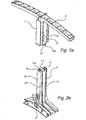
- Figures 2a and 2b show a first upper and a second lower part, respectively, of a module 2 according to a preferred embodiment of the invention.
- Figures 3a and 3b show a side view of the corresponding parts.
- the upper part comprises a second part 7 of the intermediate member of the module and the outer member 4 of the module.
- the lower part comprises a first part 6 of the intermediate member and the inner member 3 of the module.
- the upper and lower parts comprise means 10 and 11 for connection.
- the connection means 10 and 11 are provided on the connection surfaces 12 and 13, respectively, of the upper and lower part.
- the connection surfaces 12 and 13 are those end surfaces of the parts of the intermediate member which abut when the parts are connected.
- each connection surface has a corresponding connection surface on another of the parts of the intermediate member.
- the connection surfaces 12 and 13 correspond to each other. If the intermediate member consists of more than two parts, some parts will have two connection surfaces, which correspond to connection surfaces located on two different parts of the intermediate member.
- connection surfaces have a normal direction which points in the radial direction of the disc filter, which facilitates connection of the parts of the intermediate member in radial direction.
- connection surfaces can be designed as surfaces having a normal direction at a 45° angle from the radial direction of the disc filter.
- connection means 10 and 11 can basically be formed by any means serving the purpose of connecting the parts of the intermediate member. However, they preferably comprise at least one protrusion 10a on one of the connection surfaces, in this case the connection surface 12, and a corresponding cavity 11 a on another corresponding connection surface, in this case connection surface 13.
- the connection means 10 and 11 comprise two protrusions 10a and two corresponding cavities 11 a.
- the design of the protrusions 10a is such that it engages with the corresponding cavity 11 a.
- the protrusions are designed such that, when engaging with the cavities, they are secured with the same. This way, a connection which keeps the parts 6 and 7 of the intermediate member 5 securely together is provided.
- the protrusions 10a are designed as pins which extend outwardly from the connection surface 12. These pins have a rectangular cross-section which matches the shape of the holes 11 which form corresponding cavities 11 a on the connection surface 13.
- the most protruding part 14 of the protrusion can be designed for hooking into hooking means 15, which are provided below the cavity 11 a.
- the most protruding part 14 is designed as a small hook which extends along the edge of the part 14. This hook is designed in order to hook into hooking means 15 which are provided below the cavity 11 a.
- These hooking means 15 are, in this case, provided on the bottom side of the connection surface 13, which is facilitated by the first part 6 of the intermediate member having a cavity below the connection surface 13.
- the hooking means are designed as protrusions which are provided on the bottom side of the connection surface 13 and which extend obliquely outwards from this.
- the position of the hooking means 15 on the bottom side of the connection surface 13, at which the hooking means 15 is attached and the angle which the protrusions of the hooking means 15 form with this surface is preferably adapted such that the tips of the protrusions go straight underneath the cavities 11. Further, the distance between the connection surface 13 and the tips of the protrusions of the hooking means 15 is preferably adjusted such that this distance matches the length of the protrusions 10a which are inserted through the cavities 11a, which in this case comprise holes in the connection surface 13. In this way, the hook on the most protruding part 14 of the protrusion 10a will be able to fit into and hook into the hooking means 15, as the protrusion 10a is inserted into the cavity 11a. This facilitates that the parts of the intermediate member 5 can be easily connected and remain secured by each other.
- the hooking means can be made resilient. This is for example accomplished by the hooking means being made in a material which is not completely rigid but which can spring when being subjected to a force, which for example is met by some kinds of plastics. If the hooking means 15 are resilient, these can be pushed away by the most protruding part 14 of the protrusion 10a, which protruding part 14 is shown in figure 3a as a hook, when the protruding part 14 is inserted through the cavity 11 a and past the hooking means 15. When the most protruding part 14 has passed the tip of the hooking means 15, this can spring back and hence secure the protrusion 10a.
- the different parts of the intermediate member 5 are detachably connected. This is preferably accomplished by using elastic hooking means 15 as shown above. In order to detach the parts of the intermediate member 5, a force can be applied on the hooking means 15 and with that forcing them to spring back. Hence, the hooking of the hooking means 15 onto the most protruding part 14 of the protrusions 10a will be released, and the parts 6 and 7 of the intermediate member 5 can be detached from each other.
- connection means 10 and 11 on the connection surfaces 12 and 13 can be varied and adjusted according to the shape of the parts of the intermediate member 5 and the forces which are expected to act upon the filter frame 1 during use.
- the connection means 10 and 11 can be offset in relation to each other.
- the intermediate members have an essentially rectangular cross-section, and therefore an inappropriate location of the connection means 10 and 11 could lead to the parts 6 and 7 of the intermediate member 5 wobbling or twisting in relation to each other and hence causing instability in the filter frame 1.
- the connection means 10 and 11 can be provided along the diagonals of the connection surfaces 12 and 13, as shown in figure 2 . Hence, an increased stability can be accomplished.
- connection means 10 and 11 comprise protrusions 10a and cavities 11 a is a simple way of facilitating interconnection between the parts of the intermediate member.
- the protrusions 10a and the cavities 11 a can be formed at the same time as the rest of the module 2, and therefore the assembly and mounting of the module and the filter frame 1 will be particularly simple as there is no need for dealing with any loose connection means.
- protrusions 10a and cavities 11 a there are many good options for protrusions 10a and cavities 11 a.
- a screw or a bolt can be used for interconnection of the parts of the intermediate member. These are preferably provided through the connection surfaces 12 and 13 in order to join them.
- clamps or clasps can be used for securing the connection surfaces 12 and 13 to each other.
- bolts, screws, clamps, and clasps can be used in order to connect the parts of the intermediate member 5, without being provided on a connection surface.
- a clamp can connect two parts of the intermediate member 5 by being provided on one hand on a first part of the intermediate member 5, but not on a connection surface, and on another hand on a second part of the intermediate member 5, which is not a connection surface either.
- adhesive such as glue
- This is preferably applied on the connection surfaces of the intermediate member in order to join these together. It is also possible to combine different kinds of connection means in order to accomplish a better connection.
- the intermediate member of the module can further be provided with special grooves 16. These grooves can be accomplished by the intermediate member 5 comprising an inner part 17 and at least one front part 18, which are connected by at least one partition 19, perpendicular to the inner part 17 and the front part 18. Since the partition 19 separates the inner part 17 and the front part 18, a space which defines grooves 16 in the intermediate member is formed. When the parts of the intermediate member are connected, it is important that these are designed such that the grooves 16 are neither blocked nor obstructed. In order to be sure that there will be no problems in the joints between the parts of the intermediate member, extra connection means 20 and 21 can be provided on those surfaces of the front parts 18 which abut each other when the parts 6 and 7 of the intermediate member 5 are connected. These extra connection means 20 and 21 can for example comprise protrusions and cavities.
- connection means can be executed in a number of ways, and when they comprise protrusions and cavities, the design of these can vary.
- the hooking means can be provided in the pit instead of being protrusions which are separate from the cavity.
- the number of means for connection and the number of parts of the intermediate member can be varied as well as their design.
Landscapes
- Chemical & Material Sciences (AREA)
- Chemical Kinetics & Catalysis (AREA)
- Filtering Of Dispersed Particles In Gases (AREA)
- Snaps, Bayonet Connections, Set Pins, And Snap Rings (AREA)
- Filtration Of Liquid (AREA)
- Optical Filters (AREA)
Description
- The present invention relates to a module for assembly of a filter frame for at least one filter disc of a rotatable disc filter, which filter frame is provided for supporting at least two filter segments, which filter segments together form the outer part of said filter disc, which module comprises an intermediate member intended to be at least partially provided between two adjacent filter segments.
- A disc filter is for example used for filtration of water in purification plants. A common design of a disc filter comprises a rotating drum which is intended for receiving fluid which is to be filtered, and at least one disc shaped filter means which is provided outside the drum and which extends outwardly in the lateral direction of the drum. Fluid flows out through orifices in the drum and further through the filter means. Any particles in the fluid adhere to the filter means as the fluid passes through the filter means, and are hence separated from the fluid which passes freely through the filter means.
- Known filter means comprise a filter frame and at least one filter section supported thereof. A filter section can be made in one piece, but this is often unpractical since the entire filter section has to be replaced if there is any damage, even if the damage is limited to a smaller area. Therefore, in order to facilitate maintenance and repair of damages, the filter section is usually divided into several separate filter segments, which together form one filter section and which are detachably attached to the filter frame. That way there is no need for replacing the entire filter section if any damage occurs, but only the filter segment which has been damaged, thus decreasing both costs and the amount of time needed for maintenance and repair.
- The above described disc filter with detachably attached filter segments do in many cases work satisfactorily. But it appears that the filter frame becomes large and bulky as regards disc filters dimensioned for large flows.
SE 526,692 - Even though the module system above exhibits many desirable qualities, there is still room for improvement. When the disc filter is dimensioned for very large flows the disc filter device according to the above, despite of the modular assembly, will be bulky during transportation and the transportation space has an upper limit as regards how large the delivered disc filters can be.
- It is an object of the present invention to eliminate, or at least reduce, the above problems, and to provide a module for assembly of a filter frame for a disc filter, which module is less bulky during transportation than previously known disc filter devices.
- According to a first aspect of the present invention, these objects are achieved by providing a module for assembly of a filter frame for at least one filter disc of a rotatable disc filter, which filter frame is provided for supporting at least two filter segments, which filter segments together form the outer part of said filter disc, and which module comprises an intermediate member intended to be at least partially provided between two adjacent filter segments, characterised by the intermediate member comprising at least two parts which are interconnectable with each other in the radial direction of the disc filter.
- With this arrangement, the intermediate member of the module is not continuous, but is provided in at least two parts which can be interconnected. Hence, the size of the module, before being interconnected, can be reduced compared to the intermediate member being continuous. Subsequently, the module will be less bulky, and easier to transport compared to known modules. For example, if the intermediate member consists of two equally long parts, the length of the module in the radial direction of the disc filter can become half of the length which the module would have had if the intermediate member would have been made in one piece.
- According to one embodiment, the intermediate member extends in the radial direction of the disc filter. Such a design makes the resulting filter frame particularly stable and well supportive of any forces loaded on the disc filter.
- In some situations, it is suitable if the at least two parts of the intermediate member are not only interconnectable, but also detachable from each other. Such a situation could occur if a part of the intermediate member of a module breaks and one wishes to replace it, or if one wishes to disassemble and move the disc filter. In order to facilitate this, in one embodiment of the invention, the at least two parts of the intermediate member are detachably interconnectable.
- Preferably, the at least two parts of the intermediate member comprise means for connection of these parts. These connection means facilitate simple interconnection of the parts of the intermediate member with each other when assembling the filter frame. The connection means can be provided for interconnection of the different parts of the intermediate member, in a number of ways. In one preferred embodiment, each of the at least at least two parts of the intermediate member comprises at least one connection surface, wherein each connection surface is intended for interconnection with a corresponding connection surface of another of the parts of the intermediate member, wherein said means for connection are provided at said connection surfaces. "Connection surfaces" relates to the surfaces of parts of the intermediate member which abut each other when the intermediate member is interconnected.
- However, note that it is not necessary for the connection means to be provided on the connection surface, but it is sufficient that they are provided at, i.e. close to, the connection surface. For example, a connection means can be provided such that it, on one hand, is attached to a first part of the intermediate member, some distance from a first connection surface, and on the other hand, to a second part of the intermediate member, some distance from a second connection surface, and that these both parts are interconnected in this way.
- In one embodiment said means for connection comprises at least one protrusion on one of the connection surfaces, which protrusion is intended for engagement with at least one corresponding cavity in the corresponding connection surface. With this type of connection means, the assembly of the filter frame, and the assembly of the intermediate member in particular, becomes very simple and flexible. Since the protrusions and the cavities typically are formed on the parts of the intermediate member already during manufacture, no separate connection means are needed during assembly. Hence, the time and the level of difficulty, which is required for interconnection, are minimised.
- In order to further improve the interconnection, the most protruding part of the protrusion can be designed for hooking into hooking means, which are provided below said cavity. In this way, securing of the protrusions into the cavities is accomplished.
- Further, said hooking means can be resilient. In that way, the hooking of the outermost part of the protrusion is simplified and the securing is made stronger. Making the hooking means resilient can also simplify the detachment of two already interconnected intermediate members.
- In one embodiment, the connection surfaces of the intermediate member are essentially rectangular. In this case, in order to avoid wobbling or twisting between the parts of the intermediate member after interconnection, it is suitable to provide the means for connection such that not all connection means are situated along a line which is parallel with any of the surfaces of the connection surface. One way of accomplishing this is to provide the protrusions along a diagonal of one of the connection surfaces, and to, in the same way, provide the corresponding cavities along a corresponding diagonal of a corresponding connection surface.
- In alternate embodiments, other types of means for connection can be used. For example, at least one bolt can be provided through the connection surfaces in order to join these. Another example of means for connection is at least one clamp which is provided at one of the connection surfaces and attaching this to the corresponding connection surface. Alternatively, the connection means can comprise an adhesive which is applied to the connection surfaces for binding the surfaces to each other.
- The features which have been described above, with reference to different alternate embodiments, can either appear individually or in combination with each other.
- The invention will be described in more detail below, with reference to the appended drawings showing a currently preferred embodiment of the invention, as an example.
-
Figure 1 shows a schematic side view of a number of modules according to an embodiment of the present invention. -
Figures 2a and 2b show a perspective view of a first and a second part, respectively, of a module according to an embodiment of the present invention. -
Figures 3a and 3b show a side view of a first and a second part, respectively, of a module according to an embodiment of the invention. - The present invention refers to a module for assembly of a filter frame for at least one filter disc (not shown) of a rotatable disc filter. One example of one part of such a filter frame is shown in
figure 1 . The shownfilter frame 1 consists of three partially assembledmodules 2 which are designed according to an embodiment of the present invention. Each of themodules 2 consists of aninner member 3, anouter member 4, and anintermediate member 5. Theinner member 3 of the module is intended for abutting, and assembly with, a drum (not shown). Whenseveral modules 2 are assembled together, through the joining of theirinner members 3, theinner members 3 will together define a circle which radius coincides with the radius of the drum. From theinner member 3 of the module, anintermediate member 5 extends outwards in the lateral direction of the drum. Theintermediate member 5 consists of at least two parts which are interconnectable with each other in the radial direction of the disc filter. In the embodiment shown infigure 1 , the intermediate member consists of two parts, afirst part 6 which is connected to theinner member 3 and asecond part 7 which is connected to theouter member 4. The number of parts can be varied though, and by choosing more parts the size of the module, in a disassembled form, will become smaller and the module hence less bulky during transportation.
The design of the intermediate member can be varied. In the shown example, the angle between the inner member and the intermediate member is orthogonal, i.e. the intermediate member extends straight outwards in a radial direction. In other embodiments however, the angle between the inner member and the intermediate member can assume other values. Further, the intermediate member does not need to have a straight shape; the intermediate member can for example have a curved shape. - The
outer member 4 of the module is connected to the part of theintermediate member 5 which is intended to be fitted the farthest from the drum, in this case thesecond part 7. Theouter member 4 preferably has the shape of a circular arc such that it, together with the outer members of the other modules which form the filter frame, form a circle which is concentric with the periphery of the drum. - The
modules 2 of the described example are manufactured through injection moulding of ABS plastic. Other plastic materials can also be used, and the appropriate manufacturing method is then chosen with respect to the type of plastic. The advantage of using plastic is that it is a relatively cheap and malleable material. It is also corrosion resistant. - When
several modules 2 are connected, their inner members, intermediate members, and outer members will define acell 8 in which filter segments (not shown) can be provided on either side of thefilter frame 1. Hence, theinner members 3 will be provided between the drum and the filter segments, theouter members 4 between the filter segments and the outer periphery of the disc filter, and theintermediate members 5 at least partially between two adjacent filter segments. As is clear from the figures, the filter segments are intended to be provided essentially edge to edge with each other, wherein anintermediate member 5 overlaps and supports two adjacent filter segments. In the shown embodiment, theintermediate members 5 are also provided between two filter segments which are located at either side of a filter disc. The filter segments, which preferably are formed by frames onto which filter cloth is fitted, can be easily disposed in thecells 8 as the intermediate members have special grooves into which the filter segments can be pushed and secured. Together, the filter segments form the outer part of the essentially circular filter disc, while the inner part forms a hole for the drum. In known manner, the filter segments are provided on both sides of the filter disc and several filter discs are provided along the drum of the disc filter. - When the
modules 2 have been connected to a filter frame and the filter segments have been pushed into place in thecells 8,several covers 9 can be slipped onto and secured by screws at the outer periphery of the filter frame, i.e. at theouter members 4 of themodules 2. Eachcover 9 is, in this respect, slipped onto theouter members 4 of twoadjacent modules 2, and secured using screws. Thecovers 9 have the function of both keeping theouter members 4 of themodules 2 together in order to make thefilter frame 1 stable, and of keeping the fitter segments in place such that they remain in thecells 8. - Below, the parts of the intermediate member are described in more detail with reference to
figures 2a and 2b , andfigures 3a and 3b , respectively. -
Figures 2a and 2b show a first upper and a second lower part, respectively, of amodule 2 according to a preferred embodiment of the invention.Figures 3a and 3b show a side view of the corresponding parts. The upper part comprises asecond part 7 of the intermediate member of the module and theouter member 4 of the module. The lower part comprises afirst part 6 of the intermediate member and theinner member 3 of the module. Preferably, the upper and lower parts comprise means 10 and 11 for connection. In this case, the connection means 10 and 11 are provided on the connection surfaces 12 and 13, respectively, of the upper and lower part. The connection surfaces 12 and 13 are those end surfaces of the parts of the intermediate member which abut when the parts are connected. Since the parts of the intermediate member are intended for connection with each other, each connection surface has a corresponding connection surface on another of the parts of the intermediate member. In the shown example, the connection surfaces 12 and 13 correspond to each other. If the intermediate member consists of more than two parts, some parts will have two connection surfaces, which correspond to connection surfaces located on two different parts of the intermediate member. - In the shown example, the connection surfaces have a normal direction which points in the radial direction of the disc filter, which facilitates connection of the parts of the intermediate member in radial direction. However, other designs of the connection surfaces are possible. For example, they can be designed as surfaces having a normal direction at a 45° angle from the radial direction of the disc filter.
- The connection means 10 and 11 can basically be formed by any means serving the purpose of connecting the parts of the intermediate member. However, they preferably comprise at least one
protrusion 10a on one of the connection surfaces, in this case theconnection surface 12, and acorresponding cavity 11 a on another corresponding connection surface, in thiscase connection surface 13. In the shown example, the connection means 10 and 11 comprise twoprotrusions 10a and two correspondingcavities 11 a. Preferably, the design of theprotrusions 10a is such that it engages with the correspondingcavity 11 a. Better still, the protrusions are designed such that, when engaging with the cavities, they are secured with the same. This way, a connection which keeps theparts intermediate member 5 securely together is provided. In the embodiment according tofigure 2 , theprotrusions 10a are designed as pins which extend outwardly from theconnection surface 12. These pins have a rectangular cross-section which matches the shape of theholes 11 which form correspondingcavities 11 a on theconnection surface 13. - In order to obtain a locking effect as the
protrusion 10a is introduced into thecavity 11 a, the mostprotruding part 14 of the protrusion can be designed for hooking into hookingmeans 15, which are provided below thecavity 11 a. In the shown embodiment, the mostprotruding part 14 is designed as a small hook which extends along the edge of thepart 14. This hook is designed in order to hook into hookingmeans 15 which are provided below thecavity 11 a. These hooking means 15 are, in this case, provided on the bottom side of theconnection surface 13, which is facilitated by thefirst part 6 of the intermediate member having a cavity below theconnection surface 13. The hooking means are designed as protrusions which are provided on the bottom side of theconnection surface 13 and which extend obliquely outwards from this. The position of the hooking means 15 on the bottom side of theconnection surface 13, at which the hookingmeans 15 is attached and the angle which the protrusions of the hookingmeans 15 form with this surface, is preferably adapted such that the tips of the protrusions go straight underneath thecavities 11. Further, the distance between theconnection surface 13 and the tips of the protrusions of the hookingmeans 15 is preferably adjusted such that this distance matches the length of theprotrusions 10a which are inserted through thecavities 11a, which in this case comprise holes in theconnection surface 13. In this way, the hook on the mostprotruding part 14 of theprotrusion 10a will be able to fit into and hook into the hookingmeans 15, as theprotrusion 10a is inserted into thecavity 11a. This facilitates that the parts of theintermediate member 5 can be easily connected and remain secured by each other. - In order to further facilitate the hooking of the
protrusions 10a into the hookingmeans 15, the hooking means can be made resilient. This is for example accomplished by the hooking means being made in a material which is not completely rigid but which can spring when being subjected to a force, which for example is met by some kinds of plastics. If the hookingmeans 15 are resilient, these can be pushed away by the mostprotruding part 14 of theprotrusion 10a, which protrudingpart 14 is shown infigure 3a as a hook, when the protrudingpart 14 is inserted through thecavity 11 a and past the hookingmeans 15. When the mostprotruding part 14 has passed the tip of the hookingmeans 15, this can spring back and hence secure theprotrusion 10a. - In some situations, for example when one wants to be able to disassemble the
filter frame 1 of a disc filter, it is advantageous if the different parts of theintermediate member 5 are detachably connected. This is preferably accomplished by using elastic hookingmeans 15 as shown above. In order to detach the parts of theintermediate member 5, a force can be applied on the hookingmeans 15 and with that forcing them to spring back. Hence, the hooking of the hooking means 15 onto the mostprotruding part 14 of theprotrusions 10a will be released, and theparts intermediate member 5 can be detached from each other. - The location of the connection means 10 and 11 on the connection surfaces 12 and 13 can be varied and adjusted according to the shape of the parts of the
intermediate member 5 and the forces which are expected to act upon thefilter frame 1 during use. For example, the connection means 10 and 11 can be offset in relation to each other. In the shown embodiment, the intermediate members have an essentially rectangular cross-section, and therefore an inappropriate location of the connection means 10 and 11 could lead to theparts intermediate member 5 wobbling or twisting in relation to each other and hence causing instability in thefilter frame 1. In order to avoid this, the connection means 10 and 11 can be provided along the diagonals of the connection surfaces 12 and 13, as shown infigure 2 . Hence, an increased stability can be accomplished. - Letting the connection means 10 and 11 comprise
protrusions 10a andcavities 11 a is a simple way of facilitating interconnection between the parts of the intermediate member. Theprotrusions 10a and thecavities 11 a can be formed at the same time as the rest of themodule 2, and therefore the assembly and mounting of the module and thefilter frame 1 will be particularly simple as there is no need for dealing with any loose connection means. However, there are many good options forprotrusions 10a andcavities 11 a. For example, a screw or a bolt can be used for interconnection of the parts of the intermediate member. These are preferably provided through the connection surfaces 12 and 13 in order to join them. In a similar way, clamps or clasps can be used for securing the connection surfaces 12 and 13 to each other. Alternatively, bolts, screws, clamps, and clasps can be used in order to connect the parts of theintermediate member 5, without being provided on a connection surface. For example, a clamp can connect two parts of theintermediate member 5 by being provided on one hand on a first part of theintermediate member 5, but not on a connection surface, and on another hand on a second part of theintermediate member 5, which is not a connection surface either. A further alternative is to use adhesive, such as glue, for interconnecting the parts of the intermediate member. This is preferably applied on the connection surfaces of the intermediate member in order to join these together. It is also possible to combine different kinds of connection means in order to accomplish a better connection. - In order to receive and support filter segments, the intermediate member of the module can further be provided with
special grooves 16. These grooves can be accomplished by theintermediate member 5 comprising aninner part 17 and at least onefront part 18, which are connected by at least onepartition 19, perpendicular to theinner part 17 and thefront part 18. Since thepartition 19 separates theinner part 17 and thefront part 18, a space which definesgrooves 16 in the intermediate member is formed. When the parts of the intermediate member are connected, it is important that these are designed such that thegrooves 16 are neither blocked nor obstructed. In order to be sure that there will be no problems in the joints between the parts of the intermediate member, extra connection means 20 and 21 can be provided on those surfaces of thefront parts 18 which abut each other when theparts intermediate member 5 are connected. These extra connection means 20 and 21 can for example comprise protrusions and cavities. - It is realised that there are a number of modifications of the above described embodiment of the invention, which are feasible within the scope of the invention such as defined by the following claims. For example, the connection means can be executed in a number of ways, and when they comprise protrusions and cavities, the design of these can vary. For example, one can use cylindrical protrusions and the cavities do not necessarily need to be holes which pass through a connection surface, but can just as well be designed as a pit. In the latter case, the hooking means can be provided in the pit instead of being protrusions which are separate from the cavity. Further, the number of means for connection and the number of parts of the intermediate member can be varied as well as their design.
Claims (12)
- Module (2) for assembly of a filter frame (1) for at least one filter disc of a rotatable disc filter, which filter frame is provided for supporting at least two filter segments, which filter segments together form the outer part of said filter disc, and which module (2) comprises an intermediate member (5) intended to be at least partially provided between two adjacent filter segments, characterised by the intermediate member (5) comprising at least two parts (6, 7) which are interconnectable with each other in the radial direction of the disc filter.
- Module (2) according to claim 1, wherein the intermediate member (5) extends in the radial direction of the disc filter.
- Module (2) according to claim 2, wherein said at least two parts (6, 7) of the intermediate member (5) are detachably interconnectable.
- Module (2) according to claim 3, wherein said at least two members (6, 7) of the intermediate member (5) comprise means (10, 11) for interconnection of said at least two parts (6, 7).
- Module (2) according to claim 4, wherein each of said at least two parts (6, 7) of said intermediate member (5) comprises at least one connection surface (12, 13), wherein each connection surface is intended for interconnection with a corresponding connection surface of another of said parts (6, 7) of said intermediate member (5), wherein said means (10, 11) for connection are provided at said connection surfaces (12, 13).
- Module (2) according to claim 5, wherein said means (10, 11) for connection comprises at least one protrusion (10a) on one of said connection surfaces (12, 13), which protrusion is intended for engagement with at least one corresponding cavity (11a) in said corresponding connection surface (12, 13).
- Module (2) according to claim 6, wherein the most protruding part (14) of said at least one protrusion (10a) is designed for hooking into hooking means (15), which are provided below said at least one corresponding cavity (11 a).
- Module (2) according to claim 7, wherein said hooking means (15) is resilient.
- Module (2) according to claim 6, wherein said connection surfaces (12, 13) are essentially rectangular, and wherein said at least one protrusion (10a) of one of said connection surfaces (12, 13) is provided along a diagonal of said connection surface, and said at least one corresponding cavity (11 a) in said corresponding connection surface is provided along a corresponding diagonal of said corresponding connection surface.
- Module (2) according to claim 5, wherein said means (10, 11) for connection comprises at least one bolt provided through said connection surfaces (12, 13) in order to join these.
- Module (2) according to claim 5, wherein said means (10, 11) for connection comprises at least one clamp provided at one of said connection surfaces (12, 13) and attaching this to said corresponding connection surface.
- Module (2) according to any of claims 5-11, wherein said means (10, 11) for connection comprises an adhesive applied to said connection surfaces (12, 13) in order to bind said surfaces to each other.
Priority Applications (1)
| Application Number | Priority Date | Filing Date | Title |
|---|---|---|---|
| PL10772345T PL2427253T3 (en) | 2009-05-06 | 2010-05-05 | Module for assembly of a disc filter |
Applications Claiming Priority (2)
| Application Number | Priority Date | Filing Date | Title |
|---|---|---|---|
| SE0950317A SE533771C2 (en) | 2009-05-06 | 2009-05-06 | Module for the construction of disc filters |
| PCT/SE2010/050498 WO2010128944A1 (en) | 2009-05-06 | 2010-05-05 | Module for assembly of a disc filter |
Publications (3)
| Publication Number | Publication Date |
|---|---|
| EP2427253A1 EP2427253A1 (en) | 2012-03-14 |
| EP2427253A4 EP2427253A4 (en) | 2012-10-03 |
| EP2427253B1 true EP2427253B1 (en) | 2014-07-23 |
Family
ID=43050289
Family Applications (1)
| Application Number | Title | Priority Date | Filing Date |
|---|---|---|---|
| EP10772345.4A Active EP2427253B1 (en) | 2009-05-06 | 2010-05-05 | Module for assembly of a disc filter |
Country Status (13)
| Country | Link |
|---|---|
| US (1) | US8864991B2 (en) |
| EP (1) | EP2427253B1 (en) |
| JP (1) | JP5450798B2 (en) |
| KR (1) | KR101688674B1 (en) |
| CN (1) | CN102421496B (en) |
| AU (1) | AU2010245323B2 (en) |
| CA (1) | CA2760969C (en) |
| DK (1) | DK2427253T3 (en) |
| ES (1) | ES2512116T3 (en) |
| PL (1) | PL2427253T3 (en) |
| PT (1) | PT2427253E (en) |
| SE (1) | SE533771C2 (en) |
| WO (1) | WO2010128944A1 (en) |
Cited By (1)
| Publication number | Priority date | Publication date | Assignee | Title |
|---|---|---|---|---|
| EP4364823A1 (en) | 2022-11-03 | 2024-05-08 | Landel, Viktor | Disc filter |
Families Citing this family (13)
| Publication number | Priority date | Publication date | Assignee | Title |
|---|---|---|---|---|
| EP2514500B8 (en) * | 2011-04-20 | 2015-01-28 | Rosa, Tiziana | Rotary disc filter structure |
| US9803437B2 (en) * | 2012-06-11 | 2017-10-31 | M-I L.L.C. | Shaker screen assembly |
| CZ306534B6 (en) | 2013-09-30 | 2017-03-01 | In - Eko Team S.R.O. | A disc filter |
| US9555349B2 (en) * | 2014-04-11 | 2017-01-31 | Advanced Filtration Technologies Inc. | Rotary disc filter device |
| US9551306B2 (en) * | 2014-07-09 | 2017-01-24 | Caterpillar Inc. | Air filtration element |
| TWI586423B (en) * | 2015-03-12 | 2017-06-11 | 傑智環境科技股份有限公司 | Rotating wheel, fluid treatment apparatus and method for removing treatment canister |
| US10729994B2 (en) * | 2015-12-03 | 2020-08-04 | Veolia Water Solutions & Technologies Support | Rotary disc filter |
| GB2568938B (en) * | 2017-12-01 | 2020-12-30 | Dyson Technology Ltd | A filter assembly |
| GB2568937B (en) * | 2017-12-01 | 2020-08-12 | Dyson Technology Ltd | A fan assembly |
| CN109200656B (en) * | 2018-11-13 | 2024-06-25 | 华能渑池热电有限责任公司 | A light tail clamp guide rail for disc filter |
| US11000791B2 (en) * | 2019-03-06 | 2021-05-11 | Veolia Water Solutions & Technologies Support | Rotary disc filter having backwash guides |
| CN110681208B (en) * | 2019-10-29 | 2025-07-25 | 中信重工机械股份有限公司 | Fixed ring of installation disc filter plate |
| WO2026018290A1 (en) * | 2024-07-18 | 2026-01-22 | Giammarco Maria Luigia | Filtration apparatus and method of use of a filtration apparatus |
Family Cites Families (8)
| Publication number | Priority date | Publication date | Assignee | Title |
|---|---|---|---|---|
| US3917534A (en) * | 1974-04-17 | 1975-11-04 | Plastic Tech Inc | Filter sector |
| US4203846A (en) * | 1978-04-24 | 1980-05-20 | Albany International Corporation | Disc sector |
| FI912760A7 (en) * | 1991-06-07 | 1992-12-08 | Tamfelt Oy Ab | SKIVFILTER OCH FILTERELEMENT FOER SKIVFILTER |
| AT401355B (en) * | 1994-09-08 | 1996-08-26 | Andritz Patentverwaltung | DISC FILTERS FOR SEPARATING LIQUIDS FROM A SUSPENSION, IN PARTICULAR FIBER FIBER SUSPENSION |
| CA2169205A1 (en) * | 1995-02-10 | 1996-08-11 | David E. Tweet | Filter sector constructions |
| CN2265233Y (en) * | 1996-05-08 | 1997-10-22 | 沈阳电力机械总厂 | Rotary filtering-net |
| US5925248A (en) * | 1997-07-18 | 1999-07-20 | Minerals Processing Techniques, Inc. | Disk filter sector having an attachment system outside of flow area |
| SE526692E (en) * | 2003-02-27 | 2013-07-16 | Veolia Water Solutions & Tech | Module for structure of disk filter |
-
2009
- 2009-05-06 SE SE0950317A patent/SE533771C2/en unknown
-
2010
- 2010-05-05 US US13/318,909 patent/US8864991B2/en active Active
- 2010-05-05 AU AU2010245323A patent/AU2010245323B2/en active Active
- 2010-05-05 EP EP10772345.4A patent/EP2427253B1/en active Active
- 2010-05-05 CA CA2760969A patent/CA2760969C/en active Active
- 2010-05-05 ES ES10772345.4T patent/ES2512116T3/en active Active
- 2010-05-05 KR KR1020117028993A patent/KR101688674B1/en active Active
- 2010-05-05 PT PT107723454T patent/PT2427253E/en unknown
- 2010-05-05 DK DK10772345.4T patent/DK2427253T3/en active
- 2010-05-05 WO PCT/SE2010/050498 patent/WO2010128944A1/en not_active Ceased
- 2010-05-05 PL PL10772345T patent/PL2427253T3/en unknown
- 2010-05-05 CN CN201080019551.2A patent/CN102421496B/en active Active
- 2010-05-05 JP JP2012509767A patent/JP5450798B2/en active Active
Cited By (1)
| Publication number | Priority date | Publication date | Assignee | Title |
|---|---|---|---|---|
| EP4364823A1 (en) | 2022-11-03 | 2024-05-08 | Landel, Viktor | Disc filter |
Also Published As
| Publication number | Publication date |
|---|---|
| CA2760969C (en) | 2018-07-31 |
| AU2010245323B2 (en) | 2014-09-25 |
| EP2427253A1 (en) | 2012-03-14 |
| PT2427253E (en) | 2014-10-16 |
| CN102421496A (en) | 2012-04-18 |
| JP5450798B2 (en) | 2014-03-26 |
| SE533771C2 (en) | 2010-12-28 |
| KR101688674B1 (en) | 2016-12-21 |
| ES2512116T3 (en) | 2014-10-23 |
| DK2427253T3 (en) | 2014-09-22 |
| KR20120036306A (en) | 2012-04-17 |
| CN102421496B (en) | 2015-02-18 |
| JP2012525968A (en) | 2012-10-25 |
| US20120103890A1 (en) | 2012-05-03 |
| SE0950317A1 (en) | 2010-11-07 |
| AU2010245323A1 (en) | 2011-11-10 |
| US8864991B2 (en) | 2014-10-21 |
| CA2760969A1 (en) | 2010-11-11 |
| EP2427253A4 (en) | 2012-10-03 |
| WO2010128944A1 (en) | 2010-11-11 |
| PL2427253T3 (en) | 2014-12-31 |
Similar Documents
| Publication | Publication Date | Title |
|---|---|---|
| EP2427253B1 (en) | Module for assembly of a disc filter | |
| EP3197583B1 (en) | V-type filter frame | |
| US7976705B2 (en) | Filtration assemblies and methods of installing filtration units in filtration assemblies | |
| EP3197584B1 (en) | V-type filter frame | |
| CA2847251C (en) | A filter segment with a light weight frame | |
| CN113877288A (en) | Rotary disc filter | |
| KR101942810B1 (en) | Submerged hollow fiber membrane module | |
| CA2773944A1 (en) | Fastening element | |
| US20220134261A1 (en) | Modular filter element frame | |
| US20180214800A1 (en) | Filter segment with a light weight frame | |
| KR101180928B1 (en) | A Fuel Tank of Air Filter For Vehicles | |
| JP7035398B2 (en) | Water collection structure | |
| AU2019203261B2 (en) | Filter frame for air conditioners | |
| US20100072340A1 (en) | Interlocking brackets for filter capsules and method of forming the same | |
| KR101773415B1 (en) | Fiber Filter Having Fixing Apparatus for Easy Installation and Replacement of Fiber Media | |
| CN108970231B (en) | Filtration system and replacement method thereof | |
| JP2017170286A (en) | Membrane separator, extension membrane case, membrane separator set and replacing method of membrane element | |
| KR20120004226U (en) | filter | |
| HU230101B1 (en) | Filter panel for handling liquids, especially for disc wastewater filtration systems |
Legal Events
| Date | Code | Title | Description |
|---|---|---|---|
| PUAI | Public reference made under article 153(3) epc to a published international application that has entered the european phase |
Free format text: ORIGINAL CODE: 0009012 |
|
| 17P | Request for examination filed |
Effective date: 20111103 |
|
| AK | Designated contracting states |
Kind code of ref document: A1 Designated state(s): AL AT BE BG CH CY CZ DE DK EE ES FI FR GB GR HR HU IE IS IT LI LT LU LV MC MK MT NL NO PL PT RO SE SI SK SM TR |
|
| DAX | Request for extension of the european patent (deleted) | ||
| A4 | Supplementary search report drawn up and despatched |
Effective date: 20120904 |
|
| RIC1 | Information provided on ipc code assigned before grant |
Ipc: B01D 33/23 20060101ALI20120829BHEP Ipc: B01D 33/21 20060101AFI20120829BHEP |
|
| GRAP | Despatch of communication of intention to grant a patent |
Free format text: ORIGINAL CODE: EPIDOSNIGR1 |
|
| INTG | Intention to grant announced |
Effective date: 20140324 |
|
| GRAS | Grant fee paid |
Free format text: ORIGINAL CODE: EPIDOSNIGR3 |
|
| GRAA | (expected) grant |
Free format text: ORIGINAL CODE: 0009210 |
|
| AK | Designated contracting states |
Kind code of ref document: B1 Designated state(s): AL AT BE BG CH CY CZ DE DK EE ES FI FR GB GR HR HU IE IS IT LI LT LU LV MC MK MT NL NO PL PT RO SE SI SK SM TR |
|
| REG | Reference to a national code |
Ref country code: GB Ref legal event code: FG4D |
|
| REG | Reference to a national code |
Ref country code: CH Ref legal event code: EP |
|
| REG | Reference to a national code |
Ref country code: IE Ref legal event code: FG4D |
|
| REG | Reference to a national code |
Ref country code: AT Ref legal event code: REF Ref document number: 678539 Country of ref document: AT Kind code of ref document: T Effective date: 20140815 |
|
| REG | Reference to a national code |
Ref country code: DE Ref legal event code: R096 Ref document number: 602010017759 Country of ref document: DE Effective date: 20140904 |
|
| REG | Reference to a national code |
Ref country code: DK Ref legal event code: T3 Effective date: 20140916 |
|
| REG | Reference to a national code |
Ref country code: CH Ref legal event code: NV Representative=s name: FIAMMENGHI-FIAMMENGHI, CH |
|
| REG | Reference to a national code |
Ref country code: PT Ref legal event code: SC4A Free format text: AVAILABILITY OF NATIONAL TRANSLATION Effective date: 20141009 |
|
| REG | Reference to a national code |
Ref country code: ES Ref legal event code: FG2A Ref document number: 2512116 Country of ref document: ES Kind code of ref document: T3 Effective date: 20141023 |
|
| REG | Reference to a national code |
Ref country code: SE Ref legal event code: TRGR |
|
| REG | Reference to a national code |
Ref country code: NL Ref legal event code: T3 |
|
| REG | Reference to a national code |
Ref country code: EE Ref legal event code: FG4A Ref document number: E009695 Country of ref document: EE Effective date: 20141017 |
|
| REG | Reference to a national code |
Ref country code: PL Ref legal event code: T3 |
|
| REG | Reference to a national code |
Ref country code: GR Ref legal event code: EP Ref document number: 20140402135 Country of ref document: GR Effective date: 20141121 |
|
| PG25 | Lapsed in a contracting state [announced via postgrant information from national office to epo] |
Ref country code: NO Free format text: LAPSE BECAUSE OF FAILURE TO SUBMIT A TRANSLATION OF THE DESCRIPTION OR TO PAY THE FEE WITHIN THE PRESCRIBED TIME-LIMIT Effective date: 20141023 Ref country code: BG Free format text: LAPSE BECAUSE OF FAILURE TO SUBMIT A TRANSLATION OF THE DESCRIPTION OR TO PAY THE FEE WITHIN THE PRESCRIBED TIME-LIMIT Effective date: 20141023 |
|
| PG25 | Lapsed in a contracting state [announced via postgrant information from national office to epo] |
Ref country code: HR Free format text: LAPSE BECAUSE OF FAILURE TO SUBMIT A TRANSLATION OF THE DESCRIPTION OR TO PAY THE FEE WITHIN THE PRESCRIBED TIME-LIMIT Effective date: 20140723 Ref country code: IS Free format text: LAPSE BECAUSE OF FAILURE TO SUBMIT A TRANSLATION OF THE DESCRIPTION OR TO PAY THE FEE WITHIN THE PRESCRIBED TIME-LIMIT Effective date: 20141123 Ref country code: CY Free format text: LAPSE BECAUSE OF FAILURE TO SUBMIT A TRANSLATION OF THE DESCRIPTION OR TO PAY THE FEE WITHIN THE PRESCRIBED TIME-LIMIT Effective date: 20140723 |
|
| REG | Reference to a national code |
Ref country code: DE Ref legal event code: R097 Ref document number: 602010017759 Country of ref document: DE |
|
| REG | Reference to a national code |
Ref country code: HU Ref legal event code: AG4A Ref document number: E022284 Country of ref document: HU |
|
| PG25 | Lapsed in a contracting state [announced via postgrant information from national office to epo] |
Ref country code: RO Free format text: LAPSE BECAUSE OF FAILURE TO SUBMIT A TRANSLATION OF THE DESCRIPTION OR TO PAY THE FEE WITHIN THE PRESCRIBED TIME-LIMIT Effective date: 20140723 Ref country code: SK Free format text: LAPSE BECAUSE OF FAILURE TO SUBMIT A TRANSLATION OF THE DESCRIPTION OR TO PAY THE FEE WITHIN THE PRESCRIBED TIME-LIMIT Effective date: 20140723 |
|
| PLBE | No opposition filed within time limit |
Free format text: ORIGINAL CODE: 0009261 |
|
| STAA | Information on the status of an ep patent application or granted ep patent |
Free format text: STATUS: NO OPPOSITION FILED WITHIN TIME LIMIT |
|
| 26N | No opposition filed |
Effective date: 20150424 |
|
| PG25 | Lapsed in a contracting state [announced via postgrant information from national office to epo] |
Ref country code: SI Free format text: LAPSE BECAUSE OF FAILURE TO SUBMIT A TRANSLATION OF THE DESCRIPTION OR TO PAY THE FEE WITHIN THE PRESCRIBED TIME-LIMIT Effective date: 20140723 |
|
| PG25 | Lapsed in a contracting state [announced via postgrant information from national office to epo] |
Ref country code: LU Free format text: LAPSE BECAUSE OF FAILURE TO SUBMIT A TRANSLATION OF THE DESCRIPTION OR TO PAY THE FEE WITHIN THE PRESCRIBED TIME-LIMIT Effective date: 20150505 Ref country code: MC Free format text: LAPSE BECAUSE OF FAILURE TO SUBMIT A TRANSLATION OF THE DESCRIPTION OR TO PAY THE FEE WITHIN THE PRESCRIBED TIME-LIMIT Effective date: 20140723 |
|
| REG | Reference to a national code |
Ref country code: FR Ref legal event code: PLFP Year of fee payment: 7 |
|
| PG25 | Lapsed in a contracting state [announced via postgrant information from national office to epo] |
Ref country code: MT Free format text: LAPSE BECAUSE OF FAILURE TO SUBMIT A TRANSLATION OF THE DESCRIPTION OR TO PAY THE FEE WITHIN THE PRESCRIBED TIME-LIMIT Effective date: 20140723 |
|
| REG | Reference to a national code |
Ref country code: FR Ref legal event code: PLFP Year of fee payment: 8 |
|
| PG25 | Lapsed in a contracting state [announced via postgrant information from national office to epo] |
Ref country code: SM Free format text: LAPSE BECAUSE OF FAILURE TO SUBMIT A TRANSLATION OF THE DESCRIPTION OR TO PAY THE FEE WITHIN THE PRESCRIBED TIME-LIMIT Effective date: 20140723 |
|
| REG | Reference to a national code |
Ref country code: FR Ref legal event code: PLFP Year of fee payment: 9 |
|
| PG25 | Lapsed in a contracting state [announced via postgrant information from national office to epo] |
Ref country code: MK Free format text: LAPSE BECAUSE OF FAILURE TO SUBMIT A TRANSLATION OF THE DESCRIPTION OR TO PAY THE FEE WITHIN THE PRESCRIBED TIME-LIMIT Effective date: 20140723 |
|
| PG25 | Lapsed in a contracting state [announced via postgrant information from national office to epo] |
Ref country code: AL Free format text: LAPSE BECAUSE OF FAILURE TO SUBMIT A TRANSLATION OF THE DESCRIPTION OR TO PAY THE FEE WITHIN THE PRESCRIBED TIME-LIMIT Effective date: 20140723 |
|
| PGFP | Annual fee paid to national office [announced via postgrant information from national office to epo] |
Ref country code: IT Payment date: 20190423 Year of fee payment: 17 Ref country code: PT Payment date: 20190503 Year of fee payment: 10 |
|
| PGFP | Annual fee paid to national office [announced via postgrant information from national office to epo] |
Ref country code: EE Payment date: 20190522 Year of fee payment: 10 Ref country code: GR Payment date: 20190529 Year of fee payment: 10 Ref country code: LV Payment date: 20190521 Year of fee payment: 10 Ref country code: HU Payment date: 20190424 Year of fee payment: 10 |
|
| REG | Reference to a national code |
Ref country code: EE Ref legal event code: MM4A Ref document number: E009695 Country of ref document: EE Effective date: 20200531 |
|
| REG | Reference to a national code |
Ref country code: LT Ref legal event code: MM4D Effective date: 20200505 |
|
| PG25 | Lapsed in a contracting state [announced via postgrant information from national office to epo] |
Ref country code: EE Free format text: LAPSE BECAUSE OF NON-PAYMENT OF DUE FEES Effective date: 20200531 Ref country code: HU Free format text: LAPSE BECAUSE OF NON-PAYMENT OF DUE FEES Effective date: 20200506 Ref country code: PT Free format text: LAPSE BECAUSE OF NON-PAYMENT OF DUE FEES Effective date: 20201105 Ref country code: GR Free format text: LAPSE BECAUSE OF NON-PAYMENT OF DUE FEES Effective date: 20201209 Ref country code: LT Free format text: LAPSE BECAUSE OF NON-PAYMENT OF DUE FEES Effective date: 20200505 Ref country code: CZ Free format text: LAPSE BECAUSE OF NON-PAYMENT OF DUE FEES Effective date: 20200505 |
|
| PG25 | Lapsed in a contracting state [announced via postgrant information from national office to epo] |
Ref country code: LV Free format text: LAPSE BECAUSE OF NON-PAYMENT OF DUE FEES Effective date: 20200505 |
|
| P01 | Opt-out of the competence of the unified patent court (upc) registered |
Effective date: 20230526 |
|
| PGFP | Annual fee paid to national office [announced via postgrant information from national office to epo] |
Ref country code: NL Payment date: 20250522 Year of fee payment: 16 |
|
| PGFP | Annual fee paid to national office [announced via postgrant information from national office to epo] |
Ref country code: FI Payment date: 20250520 Year of fee payment: 16 |
|
| PGFP | Annual fee paid to national office [announced via postgrant information from national office to epo] |
Ref country code: PL Payment date: 20250417 Year of fee payment: 16 Ref country code: DE Payment date: 20250519 Year of fee payment: 16 |
|
| PGFP | Annual fee paid to national office [announced via postgrant information from national office to epo] |
Ref country code: GB Payment date: 20250527 Year of fee payment: 16 Ref country code: ES Payment date: 20250616 Year of fee payment: 16 Ref country code: DK Payment date: 20250521 Year of fee payment: 16 |
|
| PGFP | Annual fee paid to national office [announced via postgrant information from national office to epo] |
Ref country code: BE Payment date: 20250523 Year of fee payment: 16 |
|
| PGFP | Annual fee paid to national office [announced via postgrant information from national office to epo] |
Ref country code: FR Payment date: 20250526 Year of fee payment: 16 |
|
| PGFP | Annual fee paid to national office [announced via postgrant information from national office to epo] |
Ref country code: CH Payment date: 20250601 Year of fee payment: 16 |
|
| PGFP | Annual fee paid to national office [announced via postgrant information from national office to epo] |
Ref country code: AT Payment date: 20250519 Year of fee payment: 16 |
|
| PGFP | Annual fee paid to national office [announced via postgrant information from national office to epo] |
Ref country code: TR Payment date: 20250428 Year of fee payment: 16 |
|
| PGFP | Annual fee paid to national office [announced via postgrant information from national office to epo] |
Ref country code: IE Payment date: 20250521 Year of fee payment: 16 |
|
| PGFP | Annual fee paid to national office [announced via postgrant information from national office to epo] |
Ref country code: SE Payment date: 20250522 Year of fee payment: 16 |