EP2432093A2 - Power distribution system for an aircraft - Google Patents
Power distribution system for an aircraft Download PDFInfo
- Publication number
- EP2432093A2 EP2432093A2 EP11181509A EP11181509A EP2432093A2 EP 2432093 A2 EP2432093 A2 EP 2432093A2 EP 11181509 A EP11181509 A EP 11181509A EP 11181509 A EP11181509 A EP 11181509A EP 2432093 A2 EP2432093 A2 EP 2432093A2
- Authority
- EP
- European Patent Office
- Prior art keywords
- power distribution
- voltage
- distribution system
- power
- bus
- Prior art date
- Legal status (The legal status is an assumption and is not a legal conclusion. Google has not performed a legal analysis and makes no representation as to the accuracy of the status listed.)
- Withdrawn
Links
Images


Classifications
-
- H—ELECTRICITY
- H02—GENERATION; CONVERSION OR DISTRIBUTION OF ELECTRIC POWER
- H02J—ELECTRIC POWER NETWORKS; CIRCUIT ARRANGEMENTS OR SYSTEMS FOR SUPPLYING OR DISTRIBUTING ELECTRIC POWER; SYSTEMS FOR STORING ELECTRIC ENERGY
- H02J4/00—Circuit arrangements for mains or distribution networks not specified as AC or DC; Circuit arrangements for mains or distribution networks combining AC and DC sections or sub-networks
-
- B—PERFORMING OPERATIONS; TRANSPORTING
- B60—VEHICLES IN GENERAL
- B60L—PROPULSION OF ELECTRICALLY-PROPELLED VEHICLES; SUPPLYING ELECTRIC POWER FOR AUXILIARY EQUIPMENT OF ELECTRICALLY-PROPELLED VEHICLES; ELECTRODYNAMIC BRAKE SYSTEMS FOR VEHICLES IN GENERAL; MAGNETIC SUSPENSION OR LEVITATION FOR VEHICLES; MONITORING OPERATING VARIABLES OF ELECTRICALLY-PROPELLED VEHICLES; ELECTRIC SAFETY DEVICES FOR ELECTRICALLY-PROPELLED VEHICLES
- B60L1/00—Supplying electric power to auxiliary equipment of vehicles
-
- B—PERFORMING OPERATIONS; TRANSPORTING
- B60—VEHICLES IN GENERAL
- B60R—VEHICLES, VEHICLE FITTINGS, OR VEHICLE PARTS, NOT OTHERWISE PROVIDED FOR
- B60R16/00—Electric or fluid circuits specially adapted for vehicles and not otherwise provided for; Arrangement of elements of electric or fluid circuits specially adapted for vehicles and not otherwise provided for
- B60R16/02—Electric or fluid circuits specially adapted for vehicles and not otherwise provided for; Arrangement of elements of electric or fluid circuits specially adapted for vehicles and not otherwise provided for electric constitutive elements
- B60R16/03—Electric or fluid circuits specially adapted for vehicles and not otherwise provided for; Arrangement of elements of electric or fluid circuits specially adapted for vehicles and not otherwise provided for electric constitutive elements for supply of electrical power to vehicle subsystems or for
-
- H—ELECTRICITY
- H02—GENERATION; CONVERSION OR DISTRIBUTION OF ELECTRIC POWER
- H02J—ELECTRIC POWER NETWORKS; CIRCUIT ARRANGEMENTS OR SYSTEMS FOR SUPPLYING OR DISTRIBUTING ELECTRIC POWER; SYSTEMS FOR STORING ELECTRIC ENERGY
- H02J3/00—Circuit arrangements for AC mains or AC distribution networks
-
- B—PERFORMING OPERATIONS; TRANSPORTING
- B64—AIRCRAFT; AVIATION; COSMONAUTICS
- B64D—EQUIPMENT FOR FITTING IN OR TO AIRCRAFT; FLIGHT SUITS; PARACHUTES; ARRANGEMENT OR MOUNTING OF POWER PLANTS OR PROPULSION TRANSMISSIONS IN AIRCRAFT
- B64D2221/00—Electric power distribution systems onboard aircraft
-
- H—ELECTRICITY
- H02—GENERATION; CONVERSION OR DISTRIBUTION OF ELECTRIC POWER
- H02J—ELECTRIC POWER NETWORKS; CIRCUIT ARRANGEMENTS OR SYSTEMS FOR SUPPLYING OR DISTRIBUTING ELECTRIC POWER; SYSTEMS FOR STORING ELECTRIC ENERGY
- H02J2105/00—Networks for supplying or distributing electric power characterised by their spatial reach or by the load
- H02J2105/30—Networks for supplying or distributing electric power characterised by their spatial reach or by the load the load networks being external to vehicles, i.e. exchanging power with vehicles
- H02J2105/32—Networks for supplying or distributing electric power characterised by their spatial reach or by the load the load networks being external to vehicles, i.e. exchanging power with vehicles for aircrafts
Definitions
- the present invention relates to a power distribution system such as a power distribution system for an aircraft for example.
- One of the primary concerns for aircraft is system weight. Being able to reduce weight reduces an aircraft's fuel consumption and increases its range. An aircraft's structure, fuel, equipment and electrical wiring all contribute to its weight. The weight of electrical wiring and associated equipment for a commercial aircraft may be several hundred kilograms or several tonnes.
- a power distribution system for an aircraft.
- the power distribution system has a power distribution bus and a plurality of localised voltage converters each supplied by the power distribution bus.
- the power distribution system may use fewer, or just a single power distribution bus at a particular voltage and convert to the desired voltage at or near to each of a plurality of pieces of electrical equipment being supplied.
- This provides a considerable weight saving in electrical wiring and associated equipment such as transformers/power distribution boxes over conventional systems which typically have at least three power distribution buses along the length of an aircraft, each at a different voltage (typically 28 volts, 115 volts and 230 volts) to supply the various types of electrical equipment provided on the aircraft.
- localised voltage converters which may be provided for one or a few components, are typically much smaller and lighter than a main voltage converter for a bus supplying an entire aircraft at a particular voltage and so may be accommodated far more easily in an aircraft.
- an aircraft with a power distribution system according to the first aspect of the present invention.
- FIG 1 illustrates an aircraft 10 provided with a conventional power distribution system.
- the aircraft is provided with a number of engines 11 which, as well as providing thrust for the aircraft, provide electrical power for various pieces of electrical equipment provided on the aircraft.
- the aircraft 10 is provided with a Primary Power Distribution Box (PPDB) 13 which receives electrical power from the engines 11 via appropriate electrical connectors 12.
- the PPDB 13 contains a number of transformers to provide electrical power to at least three power buses 14, 15, 16 each at a different voltage, typically 230 volts AC, 115 volt AC and 28 volts DC.
- a single PPDB13 and corresponding set of buses 14, 15, 16 is shown in Figure 1
- an aircraft may have two or more PPDBs 13 and sets of buses 14, 15, 16. For example a set may be provided on each side of the aircraft 10 or for each engine.
- An aircraft typically has a variety of electrical components with differing power load requirements. For example some hydraulic systems, for example for operating flaps on the wings and/or lifting of landing gear will have a higher power load requirement and will typically receive power from the higher voltage bus 14. Other electrical components on the aircraft such as ovens for the galley, instruments for the cockpit and in-flight entertainment for passengers will typically require less power and may be connected to one of the other lower voltage buses 15, 16.
- electrical power is remotely converted to appropriate system voltages at the PPDB 13 and then fed to various secondary power distribution boxes (SPDB) 18 for subsequent distribution to the various aircraft components/loads.
- SPDB secondary power distribution boxes
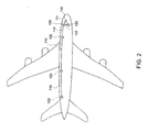
- FIG. 2 illustrates a power distribution system in accordance with an embodiment of the present invention.
- the power distribution system has a power distribution bus 110 and a plurality of localised voltage converters 120.
- the localised voltage converters 120 convert the voltage on the bus 110 to the appropriate voltage required by any loads 130 close to the converters 120, a bus 110 operating at only a single voltage is required. This significantly reduces the weight of electrical wiring compared to the arrangement shown in Figure 1 which requires separate buses 14, 15, 16 each operating at a different voltage. It is preferable that the highest system voltage is employed in the power distribution bus 110 as the size and weight of the wiring to provide the bus 110 may be reduced.
- the localised voltage converters 120 may be arranged to supply power at one or two other voltages (e.g. 28 V DC, 115 V AC) as well as at the voltage of the power distribution bus (e.g. 230 V AC).
- one or two other voltages e.g. 28 V DC, 115 V AC
- the voltage of the power distribution bus e.g. 230 V AC
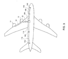
- FIG 3 shows a more detailed example of the embodiment of the present invention shown in Figure 2 .
- the Primary Power Distribution Box (PPDB) 100 can be much smaller than in the conventional power distribution shown Figure 1 as it is only required to supply one voltage as opposed to the multiple voltages provided by the PPDB 13 illustrated in Figure 1 .
- the simplified PPDB 100 of an embodiment of the present invention will consequently be significantly smaller, lighter and less expensive than the conventional PPDB 13 thus further saving weight and costs.
- the localised voltage converters 120 illustrated in Figure 2 may be integrated with the Secondary Power Distribution Boxes (SPDB) 140 illustrated in Figure 3 .
- SPDB 140 may be slightly increased in size due to the requirement for a localised voltage converter 120, this is more than made up for the simplification provided by only having to receive one supply voltage from the power distribution bus 110.
- the SPDBs 140 in embodiments of the present invention are smaller and lighter than conventional examples which receive power from several buses each at a different voltage.
- a localised voltage converter For electrical equipment which requires the voltage provided by the bus 110, a localised voltage converter will not be required at that point and so an even more simplified SPDB 150 may be used which will be arranged to receive only a single voltage from the power distribution bus 110 and which will not require a localised voltage converter.
- the SPDB 150 supplying the landing gear retractor will not require any localised voltage conversion.
- the power distribution bus 110 may provide fewer voltages, typically only a single voltage, this provides significant reduction in the weight of electrical wiring for the power distribution bus 110 as well as simplification and thus reductions in weight, size and cost of the PPDB 100 and SPDB 140.
- Figure 4 illustrates an example of a localised voltage converter 120.
- the localised voltage converter 120 receives electrical power from the bus 110 at the highest voltage of loads supplied by the power distribution system, which in this example is 230 volts AC.
- the localised voltage converter 120 provides an output at a lower voltage, which for many aircraft may be, for example, 115 volts AC or 28 volts DC, but in this example is 28 volts DC.
- the localised voltage converter 120 of this example includes a Switch Mode Power Supply (SMPS) transformer arrangement 200.
- the SMPS transformer arranged of this example is provided with the appropriate windings to be able to step up and step down to provide the desired output voltage, in this example 28 volts.
- the localised voltage converter 120 also includes a capacitor 210/diode arrangement 220 to provide AC/DC conversion and a Power Factor Correction Stage 230 to reduce phase shift.
- the SMPS arrangement 200 is provided with a unity power factor by the high voltage intermediate rail 240.
- the power distribution bus 110 preferably operates at only a single voltage and that this single voltage is preferably at the highest voltage of loads/electrical equipment supplied by the power distribution system, in this example 230 volts AC. As the bus operates at just the higher voltage, consequently, the electrical wiring of the bus 110 may be thinner than that of buses supplying a lower voltage which consequently would have a higher current.
- the power distribution bus 110 preferably also provides AC power. By operating at a relatively high switching frequency, preferably 10 kHz or above, more preferably higher than 50 kHz, a physically smaller, lighter and efficient localised voltage converter 120 may be provided. Providing a smaller and lighter localised voltage converter 120 enables it to be integrated into the aircraft structure more easily without requiring the provision of dedicated supports etc. realising further weight reduction and simplification.
- an aircraft may be provided with only one, two or more power distribution systems.
- each power distribution system may receive power from one or more engines.
Landscapes
- Engineering & Computer Science (AREA)
- Power Engineering (AREA)
- Mechanical Engineering (AREA)
- Transportation (AREA)
- Dc-Dc Converters (AREA)
- Direct Current Feeding And Distribution (AREA)
- Supply And Distribution Of Alternating Current (AREA)
Abstract
Description
- The present invention relates to a power distribution system such as a power distribution system for an aircraft for example.
- One of the primary concerns for aircraft is system weight. Being able to reduce weight reduces an aircraft's fuel consumption and increases its range. An aircraft's structure, fuel, equipment and electrical wiring all contribute to its weight. The weight of electrical wiring and associated equipment for a commercial aircraft may be several hundred kilograms or several tonnes.
- It is an aim of an embodiment of the present invention to reduce the weight of an aircraft's electrical wiring and/or associated equipment.
- According to a first aspect of the present invention, there is provided a power distribution system for an aircraft. The power distribution system has a power distribution bus and a plurality of localised voltage converters each supplied by the power distribution bus.
- By providing a plurality of localised voltage converters, the power distribution system may use fewer, or just a single power distribution bus at a particular voltage and convert to the desired voltage at or near to each of a plurality of pieces of electrical equipment being supplied. This provides a considerable weight saving in electrical wiring and associated equipment such as transformers/power distribution boxes over conventional systems which typically have at least three power distribution buses along the length of an aircraft, each at a different voltage (typically 28 volts, 115 volts and 230 volts) to supply the various types of electrical equipment provided on the aircraft.
- Furthermore, localised voltage converters, which may be provided for one or a few components, are typically much smaller and lighter than a main voltage converter for a bus supplying an entire aircraft at a particular voltage and so may be accommodated far more easily in an aircraft.
- According to a second aspect of the present invention there is provided an aircraft with a power distribution system according to the first aspect of the present invention.
- Embodiments of the present invention will now be described, by way of example only, with reference to the accompanying drawings, in which:
-
Figure 1 illustrates a conventional electrical power distribution system in an aircraft; -
Figure 2 illustrates a power distribution system of an embodiment illustrating the present invention; -
Figure 3 illustrates a more detailed example of a power distribution system of an embodiment of the present invention; and -
Figure 4 illustrates a localised power converter. -
Figure 1 illustrates anaircraft 10 provided with a conventional power distribution system. As can be seen, the aircraft is provided with a number ofengines 11 which, as well as providing thrust for the aircraft, provide electrical power for various pieces of electrical equipment provided on the aircraft. Theaircraft 10 is provided with a Primary Power Distribution Box (PPDB) 13 which receives electrical power from theengines 11 via appropriateelectrical connectors 12. The PPDB 13 contains a number of transformers to provide electrical power to at least threepower buses buses Figure 1 , an aircraft may have two ormore PPDBs 13 and sets ofbuses aircraft 10 or for each engine. - An aircraft typically has a variety of electrical components with differing power load requirements. For example some hydraulic systems, for example for operating flaps on the wings and/or lifting of landing gear will have a higher power load requirement and will typically receive power from the
higher voltage bus 14. Other electrical components on the aircraft such as ovens for the galley, instruments for the cockpit and in-flight entertainment for passengers will typically require less power and may be connected to one of the otherlower voltage buses - As can be seen in
Figure 1 electrical power is remotely converted to appropriate system voltages at thePPDB 13 and then fed to various secondary power distribution boxes (SPDB) 18 for subsequent distribution to the various aircraft components/loads. -
Figure 2 illustrates a power distribution system in accordance with an embodiment of the present invention. In this example, the power distribution system has apower distribution bus 110 and a plurality of localisedvoltage converters 120. As the localisedvoltage converters 120 convert the voltage on thebus 110 to the appropriate voltage required by anyloads 130 close to theconverters 120, abus 110 operating at only a single voltage is required. This significantly reduces the weight of electrical wiring compared to the arrangement shown inFigure 1 which requiresseparate buses power distribution bus 110 as the size and weight of the wiring to provide thebus 110 may be reduced. When a lower voltage is required for given equipment, (which for the same power will demand a higher current and thus thicker wiring), this will be locally converted by the localisedvoltage converter 120 and supplied bywiring 131 over a shorter distance. Thus, the lower voltage, higher current,thicker wiring 131 will only be required for the relatively short distances between the localisedvoltage converters 120 and the appropriatelower voltage load 130, further reducing the weight of the wiring in the power distribution system. - The localised
voltage converters 120 may be arranged to supply power at one or two other voltages (e.g. 28 V DC, 115 V AC) as well as at the voltage of the power distribution bus (e.g. 230 V AC). -
Figure 3 shows a more detailed example of the embodiment of the present invention shown inFigure 2 . As shown schematically in this example, the Primary Power Distribution Box (PPDB) 100 can be much smaller than in the conventional power distribution shownFigure 1 as it is only required to supply one voltage as opposed to the multiple voltages provided by thePPDB 13 illustrated inFigure 1 . Thesimplified PPDB 100 of an embodiment of the present invention will consequently be significantly smaller, lighter and less expensive than the conventional PPDB 13 thus further saving weight and costs. - The localised
voltage converters 120 illustrated inFigure 2 may be integrated with the Secondary Power Distribution Boxes (SPDB) 140 illustrated inFigure 3 . Whilst theSPDB 140 may be slightly increased in size due to the requirement for a localisedvoltage converter 120, this is more than made up for the simplification provided by only having to receive one supply voltage from thepower distribution bus 110. Thus overall, theSPDBs 140 in embodiments of the present invention are smaller and lighter than conventional examples which receive power from several buses each at a different voltage. - For electrical equipment which requires the voltage provided by the
bus 110, a localised voltage converter will not be required at that point and so an even moresimplified SPDB 150 may be used which will be arranged to receive only a single voltage from thepower distribution bus 110 and which will not require a localised voltage converter. For example, with thepower distribution bus 110 arranged to provide the highest available voltage for equipment on the aircraft (in this example 230 V) such as for retracting the landing gear, the SPDB 150 supplying the landing gear retractor will not require any localised voltage conversion. - Consequently, by providing a plurality of localised
voltage converters 120 such that thepower distribution bus 110 may provide fewer voltages, typically only a single voltage, this provides significant reduction in the weight of electrical wiring for thepower distribution bus 110 as well as simplification and thus reductions in weight, size and cost of thePPDB 100 andSPDB 140. -
Figure 4 illustrates an example of a localisedvoltage converter 120. In this example the localisedvoltage converter 120 receives electrical power from thebus 110 at the highest voltage of loads supplied by the power distribution system, which in this example is 230 volts AC. The localisedvoltage converter 120 provides an output at a lower voltage, which for many aircraft may be, for example, 115 volts AC or 28 volts DC, but in this example is 28 volts DC. - The localised
voltage converter 120 of this example includes a Switch Mode Power Supply (SMPS)transformer arrangement 200. The SMPS transformer arranged of this example is provided with the appropriate windings to be able to step up and step down to provide the desired output voltage, in this example 28 volts. In this example, the localisedvoltage converter 120 also includes acapacitor 210/diode arrangement 220 to provide AC/DC conversion and a PowerFactor Correction Stage 230 to reduce phase shift. TheSMPS arrangement 200 is provided with a unity power factor by the high voltageintermediate rail 240. - As explained above, the
power distribution bus 110 preferably operates at only a single voltage and that this single voltage is preferably at the highest voltage of loads/electrical equipment supplied by the power distribution system, in this example 230 volts AC. As the bus operates at just the higher voltage, consequently, the electrical wiring of thebus 110 may be thinner than that of buses supplying a lower voltage which consequently would have a higher current. Thepower distribution bus 110 preferably also provides AC power. By operating at a relatively high switching frequency, preferably 10 kHz or above, more preferably higher than 50 kHz, a physically smaller, lighter and efficient localisedvoltage converter 120 may be provided. Providing a smaller and lighter localisedvoltage converter 120 enables it to be integrated into the aircraft structure more easily without requiring the provision of dedicated supports etc. realising further weight reduction and simplification. - Although embodiments of the present invention have been described above with reference to the accompanying drawings, many variations may be made to the examples provided without departing from the present invention. For example, an aircraft may be provided with only one, two or more power distribution systems. Furthermore, each power distribution system may receive power from one or more engines.
Claims (13)
- A power distribution system for an aircraft, the power distribution system having a power distribution bus and a plurality of localised voltage converters each supplied by the power distribution bus.
- A power distribution system according to claim 1, having only a single power distribution bus.
- A power distribution system according to claim 1 or claim 2, wherein the power distribution bus is arranged to operate at just one voltage.
- A power distribution system according to any of the preceding claims, including a Primary Power Distribution Box arranged to supply power to the power distribution bus at just one voltage.
- A power distribution system according to claim 4, wherein the Primary Power Distribution Bus is arranged to receive electrical power from one or more engines.
- A power distribution system according to any of the preceding claims, including two or more Supplementary Power Distribution Boxes, each including a localised voltage converter, wherein each Supplementary Power Distribution Bus is arranged to receive only a single voltage from the bus and supply power to one or more loads at a different voltage from that provided by the power distribution bus.
- A power distribution system of any of the preceding claims, wherein the power distribution system is arranged to supply electrical power to a plurality of loads arranged to be supplied at different voltages wherein the power distribution bus is arranged to supply electrical power at the highest voltage of the loads supplied by the power distribution system.
- A power distribution system according to any of the preceding claims, wherein the localised voltage converters are arranged to supply power at one other voltage as well as at the voltage of the power distribution bus.
- The power distribution system according to any of the preceding claims, wherein the localised voltage converters are arranged to supply power at two other voltages as well as at the voltage of the power distribution bus.
- A power distribution system according to any of the preceding claims, wherein the localised voltage converters each include a power supply arranged to provide an adjustable output voltage.
- A power distribution system according to any of the preceding claims, wherein the localised voltage converters are Switch Mode Power Supply (SMPS) transformer arrangements arranged to operate at a switching frequency of 10kHz or above.
- An aircraft with a power distribution system according to any of the preceding claims.
- An aircraft according to claim 12, with two or more power distribution systems according to any of claims 1 to 11, with each power distribution system having just one bus.
Applications Claiming Priority (1)
| Application Number | Priority Date | Filing Date | Title |
|---|---|---|---|
| GB1015562.0A GB2483696B (en) | 2010-09-17 | 2010-09-17 | An aircraft with a power distribution system |
Publications (2)
| Publication Number | Publication Date |
|---|---|
| EP2432093A2 true EP2432093A2 (en) | 2012-03-21 |
| EP2432093A3 EP2432093A3 (en) | 2017-07-12 |
Family
ID=43065380
Family Applications (1)
| Application Number | Title | Priority Date | Filing Date |
|---|---|---|---|
| EP11181509.8A Withdrawn EP2432093A3 (en) | 2010-09-17 | 2011-09-15 | Power distribution system for an aircraft |
Country Status (6)
| Country | Link |
|---|---|
| US (1) | US9236744B2 (en) |
| EP (1) | EP2432093A3 (en) |
| JP (1) | JP6110588B2 (en) |
| CN (1) | CN102412512B (en) |
| CA (1) | CA2751871A1 (en) |
| GB (1) | GB2483696B (en) |
Cited By (6)
| Publication number | Priority date | Publication date | Assignee | Title |
|---|---|---|---|---|
| WO2014177817A1 (en) * | 2013-05-02 | 2014-11-06 | Labinal Power Systems | Electrical power distribution assembly for an aircraft |
| EP3018788A1 (en) * | 2014-11-07 | 2016-05-11 | Astronics Advanced Electronic Systems Corp. | Low voltage dc distribution system for charging passenger devices |
| GB2550381A (en) * | 2016-05-18 | 2017-11-22 | Ge Aviation Systems Group Ltd | An electric ditribution architecture |
| WO2018039222A1 (en) * | 2016-08-22 | 2018-03-01 | General Electric Company | Electric propulsion system |
| WO2018153821A1 (en) | 2017-02-22 | 2018-08-30 | Latecoere | Method and architecture for distributing on-board power in an aircraft |
| WO2018234330A1 (en) | 2017-06-20 | 2018-12-27 | Latelec | Electric power supply method and architecture for on-board domestic network |
Families Citing this family (14)
| Publication number | Priority date | Publication date | Assignee | Title |
|---|---|---|---|---|
| US20140032002A1 (en) * | 2012-07-30 | 2014-01-30 | The Boeing Company | Electric system stabilizing system for aircraft |
| CN104736376B (en) * | 2012-10-26 | 2016-12-14 | Abb 技术有限公司 | Rail vehicle and the power distribution system for rail vehicle |
| JP6387225B2 (en) * | 2013-11-05 | 2018-09-05 | ナブテスコ株式会社 | Aircraft power distribution system |
| GB2520024B (en) | 2013-11-06 | 2016-02-03 | Ge Aviat Systems Ltd | Electrical power system for an aircraft |
| US9809321B2 (en) * | 2014-10-30 | 2017-11-07 | The Boeing Company | Electrical power distribution system with localized distribution conversion units |
| GB2547946B (en) | 2016-03-04 | 2020-05-20 | Ge Aviat Systems Ltd | Method and apparatus for modular power distribution |
| GB2559956B (en) | 2017-02-15 | 2020-09-16 | Ge Aviat Systems Ltd | Power distribution node for a power architecture |
| JP6894821B2 (en) * | 2017-10-20 | 2021-06-30 | 川崎重工業株式会社 | Power system |
| GB2572821B (en) | 2018-04-13 | 2021-03-10 | Ge Aviat Systems Ltd | Method and apparatus for operating a power distribution system |
| GB2572825B (en) | 2018-04-13 | 2021-04-07 | Ge Aviat Systems Ltd | Method and apparatus for operating a power distribution system |
| GB2575520B (en) * | 2018-07-13 | 2021-01-27 | Ge Aviat Systems Ltd | Power distribution system |
| US11156128B2 (en) | 2018-08-22 | 2021-10-26 | General Electric Company | Embedded electric machine |
| US12149154B2 (en) | 2021-07-22 | 2024-11-19 | General Electric Company | Electric machine having a hybrid insulative-conductive manifold |
| US20250316998A1 (en) * | 2024-04-09 | 2025-10-09 | Lockheed Martin Corporation | Electric aircraft with power generation and distribution system |
Family Cites Families (18)
| Publication number | Priority date | Publication date | Assignee | Title |
|---|---|---|---|---|
| US5418707A (en) * | 1992-04-13 | 1995-05-23 | The United States Of America As Represented By The United States Department Of Energy | High voltage dc-dc converter with dynamic voltage regulation and decoupling during load-generated arcs |
| US6664656B2 (en) * | 2000-09-14 | 2003-12-16 | The Boeing Company | Aircraft electrical power distribution network |
| US6899390B2 (en) | 2001-12-12 | 2005-05-31 | The Boeing Company | Aircraft passenger seat and in-flight entertainment integrated electronics |
| US6950322B2 (en) * | 2003-04-10 | 2005-09-27 | Rsm Electron Power, Inc. | Regulated AC to DC converter for aerospace applications |
| KR100659364B1 (en) * | 2004-06-19 | 2006-12-19 | (주)에스피에스 | AC and DC power supply |
| US7922117B2 (en) * | 2004-08-30 | 2011-04-12 | Hamilton Sundstrand Corporation | Primary panel and motor controller integration for aircraft power distribution system |
| US7256513B2 (en) * | 2004-12-02 | 2007-08-14 | General Electric Company | Locomotive auxiliary power system |
| US8148842B2 (en) * | 2006-02-20 | 2012-04-03 | Hamilton Sundstrand Corporation | Electrical power generation system having multiple secondary power distribution assemblies with integral power conversion |
| FR2900636B1 (en) * | 2006-05-05 | 2009-03-06 | Hispano Suiza Sa | POWER SUPPLY CIRCUIT FOR ELECTRICAL EQUIPMENT OF AN AIRCRAFT ENGINE OR ITS ENVIRONMENT |
| US7612514B2 (en) * | 2006-11-09 | 2009-11-03 | Honeywell International Inc. | Architecture and a multiple function power converter for aircraft |
| FR2911848B1 (en) * | 2007-01-31 | 2009-12-25 | Hispano Suiza Sa | CIRCUIT FOR SUPPLYING ELECTRIC ENERGY IN AN AIRCRAFT FOR ELECTRICAL EQUIPMENT COMPRISING A DEFROST CIRCUIT |
| US7980905B2 (en) * | 2007-11-25 | 2011-07-19 | C-Mar Holdings, Ltd. | Method and apparatus for providing power to a marine vessel |
| CN102224076B (en) * | 2008-09-23 | 2014-08-27 | 飞行环境公司 | Remote device control and power supply |
| DE102008043626A1 (en) * | 2008-11-10 | 2010-05-20 | Airbus Deutschland Gmbh | Power distribution device for distributing power and method for distributing power |
| US7928597B2 (en) * | 2008-12-12 | 2011-04-19 | General Electric Company | Power system and method for driving an electromotive traction system and auxiliary equipment through a common power bus |
| FR2949436B1 (en) * | 2009-08-25 | 2012-01-27 | Thales Sa | ELECTRICAL NETWORK OF AN AIRCRAFT AND METHOD FOR OPERATING THE ELECTRICAL NETWORK |
| US20120007424A1 (en) * | 2010-07-07 | 2012-01-12 | Josef Maier | Ring power distribution loop |
| US20140084817A1 (en) * | 2010-07-20 | 2014-03-27 | Vijay Bhavaraju | Method of energy and power management in dynamic power systems with ultra-capacitors (super capacitors) |
-
2010
- 2010-09-17 GB GB1015562.0A patent/GB2483696B/en active Active
-
2011
- 2011-09-08 CA CA2751871A patent/CA2751871A1/en not_active Abandoned
- 2011-09-15 JP JP2011201246A patent/JP6110588B2/en not_active Expired - Fee Related
- 2011-09-15 EP EP11181509.8A patent/EP2432093A3/en not_active Withdrawn
- 2011-09-16 CN CN201110283539.9A patent/CN102412512B/en active Active
- 2011-09-27 US US13/225,702 patent/US9236744B2/en active Active
Non-Patent Citations (1)
| Title |
|---|
| None |
Cited By (14)
| Publication number | Priority date | Publication date | Assignee | Title |
|---|---|---|---|---|
| FR3005377A1 (en) * | 2013-05-02 | 2014-11-07 | Labinal | POWER DISTRIBUTION ASSEMBLY FOR AN AIRCRAFT |
| WO2014177817A1 (en) * | 2013-05-02 | 2014-11-06 | Labinal Power Systems | Electrical power distribution assembly for an aircraft |
| US10992140B2 (en) | 2013-05-02 | 2021-04-27 | Safran Electrical & Power | Electrical power distribution assembly for an aircraft |
| EP3018788B1 (en) | 2014-11-07 | 2019-05-15 | Astronics Advanced Electronic Systems Corp. | Low voltage dc distribution system for charging passenger devices |
| EP3018788A1 (en) * | 2014-11-07 | 2016-05-11 | Astronics Advanced Electronic Systems Corp. | Low voltage dc distribution system for charging passenger devices |
| US9887561B2 (en) | 2014-11-07 | 2018-02-06 | Astronics Advanced Electronic Systems Corp. | Low voltage DC distribution system for charging passenger devices |
| GB2550381A (en) * | 2016-05-18 | 2017-11-22 | Ge Aviation Systems Group Ltd | An electric ditribution architecture |
| US10693314B2 (en) | 2016-05-18 | 2020-06-23 | Ge Aviation Systems Limited | Electric distribution architecture |
| GB2550381B (en) * | 2016-05-18 | 2020-06-24 | Ge Aviat Systems Ltd | An electric distribution architecture |
| US10093428B2 (en) | 2016-08-22 | 2018-10-09 | General Electric Company | Electric propulsion system |
| WO2018039222A1 (en) * | 2016-08-22 | 2018-03-01 | General Electric Company | Electric propulsion system |
| WO2018153821A1 (en) | 2017-02-22 | 2018-08-30 | Latecoere | Method and architecture for distributing on-board power in an aircraft |
| US11214383B2 (en) | 2017-02-22 | 2022-01-04 | Latelec | Method and architecture for distributing on-board power in an aircraft |
| WO2018234330A1 (en) | 2017-06-20 | 2018-12-27 | Latelec | Electric power supply method and architecture for on-board domestic network |
Also Published As
| Publication number | Publication date |
|---|---|
| US9236744B2 (en) | 2016-01-12 |
| JP2012062050A (en) | 2012-03-29 |
| GB201015562D0 (en) | 2010-10-27 |
| US20120086266A1 (en) | 2012-04-12 |
| CN102412512B (en) | 2016-08-10 |
| EP2432093A3 (en) | 2017-07-12 |
| CN102412512A (en) | 2012-04-11 |
| GB2483696A (en) | 2012-03-21 |
| GB2483696B (en) | 2015-03-25 |
| JP6110588B2 (en) | 2017-04-05 |
| CA2751871A1 (en) | 2012-03-17 |
Similar Documents
| Publication | Publication Date | Title |
|---|---|---|
| US9236744B2 (en) | Power distribution system for an aircraft | |
| Nya et al. | Benefits of higher voltage levels in aircraft electrical power systems | |
| US9484749B2 (en) | Electric power supply system for an aircraft, aircraft and airport power supply system | |
| US7612514B2 (en) | Architecture and a multiple function power converter for aircraft | |
| US7800245B2 (en) | Method and architecture for reduction in vehicle wiring | |
| US8928171B2 (en) | Power distribution device for distributing power and a method for the distribution of power | |
| US10110016B2 (en) | Electrical conversion and distribution system for an aircraft | |
| US10693314B2 (en) | Electric distribution architecture | |
| CN104718104B (en) | EMS for rail vehicle | |
| JP7220662B2 (en) | Method and architecture for distributing onboard power in an aircraft | |
| Schroter et al. | The electrical aircraft network—Benefits and drawbacks of modifications | |
| Aguida et al. | Technological advancements and future prospects of electrical power systems for sustainable more electric aircraft | |
| US8148842B2 (en) | Electrical power generation system having multiple secondary power distribution assemblies with integral power conversion | |
| US11223204B2 (en) | Electric power supply method and architecture for on-board domestic network | |
| US9809321B2 (en) | Electrical power distribution system with localized distribution conversion units | |
| US8890355B2 (en) | Power distribution architecture for aircraft | |
| Eid et al. | Constant frequency aircraft electric power systems with harmonic reduction | |
| EP2654159A1 (en) | Energy supply network, method and aircraft or spacecraft | |
| US8813505B2 (en) | Method for conditioning a power supply for starting a jet engine | |
| US20190006852A1 (en) | Electrical power distribution box for onboard network of an aircraft and corresponding electrical power supply system | |
| BRPI1104173A2 (en) | ENERGY DISTRIBUTION SYSTEM FOR AN AIRCRAFT AND AIRCRAFT WITH ENERGY DISTRIBUTION SYSTEM | |
| CN110556915B (en) | Power supply system architecture of single-channel multi-electric aircraft | |
| Thalin | The Electric Aircraft |
Legal Events
| Date | Code | Title | Description |
|---|---|---|---|
| PUAI | Public reference made under article 153(3) epc to a published international application that has entered the european phase |
Free format text: ORIGINAL CODE: 0009012 |
|
| AK | Designated contracting states |
Kind code of ref document: A2 Designated state(s): AL AT BE BG CH CY CZ DE DK EE ES FI FR GB GR HR HU IE IS IT LI LT LU LV MC MK MT NL NO PL PT RO RS SE SI SK SM TR |
|
| AX | Request for extension of the european patent |
Extension state: BA ME |
|
| PUAL | Search report despatched |
Free format text: ORIGINAL CODE: 0009013 |
|
| AK | Designated contracting states |
Kind code of ref document: A3 Designated state(s): AL AT BE BG CH CY CZ DE DK EE ES FI FR GB GR HR HU IE IS IT LI LT LU LV MC MK MT NL NO PL PT RO RS SE SI SK SM TR |
|
| AX | Request for extension of the european patent |
Extension state: BA ME |
|
| RIC1 | Information provided on ipc code assigned before grant |
Ipc: H02J 4/00 20060101AFI20170602BHEP |
|
| 17P | Request for examination filed |
Effective date: 20180112 |
|
| RBV | Designated contracting states (corrected) |
Designated state(s): AL AT BE BG CH CY CZ DE DK EE ES FI FR GB GR HR HU IE IS IT LI LT LU LV MC MK MT NL NO PL PT RO RS SE SI SK SM TR |
|
| STAA | Information on the status of an ep patent application or granted ep patent |
Free format text: STATUS: THE APPLICATION IS DEEMED TO BE WITHDRAWN |
|
| 18D | Application deemed to be withdrawn |
Effective date: 20190402 |