EP2434252B1 - Vorrichtung zum Sichern und Scharfmachen eines kreiselstabilisierten Geschosses und Zündvorrichtung, die eine solche Vorrichtung zum Sichern und Scharfmachen einsetzt - Google Patents
Vorrichtung zum Sichern und Scharfmachen eines kreiselstabilisierten Geschosses und Zündvorrichtung, die eine solche Vorrichtung zum Sichern und Scharfmachen einsetzt Download PDFInfo
- Publication number
- EP2434252B1 EP2434252B1 EP20110290411 EP11290411A EP2434252B1 EP 2434252 B1 EP2434252 B1 EP 2434252B1 EP 20110290411 EP20110290411 EP 20110290411 EP 11290411 A EP11290411 A EP 11290411A EP 2434252 B1 EP2434252 B1 EP 2434252B1
- Authority
- EP
- European Patent Office
- Prior art keywords
- screens
- projectile
- ring
- safety
- rotor
- Prior art date
- Legal status (The legal status is an assumption and is not a legal conclusion. Google has not performed a legal analysis and makes no representation as to the accuracy of the status listed.)
- Active
Links
Images


Classifications
-
- F—MECHANICAL ENGINEERING; LIGHTING; HEATING; WEAPONS; BLASTING
- F42—AMMUNITION; BLASTING
- F42C—AMMUNITION FUZES; ARMING OR SAFETY MEANS THEREFOR
- F42C15/00—Arming-means in fuzes; Safety means for preventing premature detonation of fuzes or charges
- F42C15/34—Arming-means in fuzes; Safety means for preventing premature detonation of fuzes or charges wherein the safety or arming action is effected by a blocking-member in the pyrotechnic or explosive train between primer and main charge
-
- F—MECHANICAL ENGINEERING; LIGHTING; HEATING; WEAPONS; BLASTING
- F42—AMMUNITION; BLASTING
- F42C—AMMUNITION FUZES; ARMING OR SAFETY MEANS THEREFOR
- F42C15/00—Arming-means in fuzes; Safety means for preventing premature detonation of fuzes or charges
- F42C15/18—Arming-means in fuzes; Safety means for preventing premature detonation of fuzes or charges wherein a carrier for an element of the pyrotechnic or explosive train is moved
- F42C15/188—Arming-means in fuzes; Safety means for preventing premature detonation of fuzes or charges wherein a carrier for an element of the pyrotechnic or explosive train is moved using a rotatable carrier
- F42C15/192—Arming-means in fuzes; Safety means for preventing premature detonation of fuzes or charges wherein a carrier for an element of the pyrotechnic or explosive train is moved using a rotatable carrier rotatable in a plane which is parallel to the longitudinal axis of the projectile
-
- F—MECHANICAL ENGINEERING; LIGHTING; HEATING; WEAPONS; BLASTING
- F42—AMMUNITION; BLASTING
- F42C—AMMUNITION FUZES; ARMING OR SAFETY MEANS THEREFOR
- F42C15/00—Arming-means in fuzes; Safety means for preventing premature detonation of fuzes or charges
- F42C15/24—Arming-means in fuzes; Safety means for preventing premature detonation of fuzes or charges wherein the safety or arming action is effected by inertia means
- F42C15/26—Arming-means in fuzes; Safety means for preventing premature detonation of fuzes or charges wherein the safety or arming action is effected by inertia means using centrifugal force
Definitions
- the technical field of the invention is that of priming devices (rockets) of gyro-stabilized projectiles and in particular that of the safety and arming devices equipping these priming devices.
- Gyro-stabilized explosive projectiles and in particular medium-caliber projectiles (caliber less than 50 mm), most often comprise a safety and arming device that incorporates a primer rotor which is released consecutively to the firing of the projectile.
- This rotor has an imbalance that ensures alignment of the primer with the rest of the pyrotechnic priming chain.
- Licences FR-2689972 and FR-2533686 describe such safety and arming devices.
- the unbalanced rotor is placed in a cage which is free to rotate relative to the axis of the projectile.
- a disadvantage of these known devices is that they require the establishment of a primer (and therefore a pyrotechnic component) on the rotor.
- the primer must also be of relatively small size for medium-sized applications (caliber less than 50 mm).
- the patent is still known FR-1184670 describing a security and arming device comprising a screen formed of two half-screens which close off a transmission channel connecting a detonator and a pyrotechnic relay. These two screens are able to move relative to each other and transversely to the transmission channel and being locked in the closed position by a first inertial lock fading when firing the projectile. In this device, there is no interaction with a rotor.
- the object of the invention is to propose a safety and arming device that is easily integrable into a projectile, even of reduced caliber. This device allows the use of an electric initiation detonator without imposing its implementation in a rotor.
- the invention thus proposes a safety and arming device which can be housed in the bulk of the known rotor devices.
- the subject of the invention is a safety and arming device for a gyro-stabilized explosive projectile, a device comprising a screen closing a transmission channel connecting a detonator and a pyrotechnic relay, the screen consisting of two half-screens.
- the two half-screens closing the channel when in contact with each other, the two half-screens being slidably mounted in a bore, the two half-screens being moreover locked in the closed position of the channel by a first latch or inertial lock which fades when firing the projectile, characterized in that said bore is carried by a coaxial rotor at projectile, rotor which is itself pivotally mounted relative to the axis of the projectile and which carries the transmission channel, and in that the two half-screens are also locked in the closed position of the channel by a second lock or centrifugal latch which is constituted by a spiral spring surrounding an outer cylindrical surface of the rotor and thus applied against the ends of the half-screens, spiral unwinding under the effect of the centrifugal force.
- a first latch or inertial lock which fades when firing the projectile
- the half-screens are made in the form of cylindrical rods, having an end in contact with the spiral which is in the form of a spherical cap.
- the rods forming the half-screens will preferably contact each other by their ends comprising conical machining of complementary shapes.
- the first lock may be constituted by a ring slidably mounted relative to the rotor and having an internal conical bearing surface which abuts against the half-screens, the ring comprising an external groove receiving a circular metal ring which bears on an integral abutment. device, ring ensuring the axial immobilization of the ring before firing the projectile and which is deformed by the effect of the axial acceleration during firing to escape the stop and allow the translation of the ring.
- the metal ring is carried by a circular rim of the ring which is introduced during the translation of the ring in a groove of a fixed plate.
- the invention also relates to a priming device comprising such a safety and arming device, ignition device incorporating an electric initiation detonator whose mounting and integration are facilitated.
- This priming device is characterized in that the detonator is disposed along the axis of the projectile and connected to an electronic card of a firing module.
- the electronic card may carry a cup surrounding at least partially the detonator cup ensuring electrical contact between the card and the detonator.
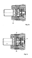
- a priming device (or rocket) 1 according to the invention comprises a firing module 2 which incorporates an electronic card 3 on which is fixed a detonator 4.
- the detonator 4 is electric initiation. It comprises an axial pin 4a which is directly connected to the electronic card 3. Moreover, the electronic card 3 carries a conductive cup 5 (soldered to the card) which at least partially surrounds the detonator 4 and provides another electrical contact between card 3 and detonator 4.
- the detonator 4 is here fixed, arranged along the axis 6 of the projectile and connected to the electronic card 3 of the firing module 2.
- the electronic module 2 is disposed in a base 7 which closes the rear of a projectile and it is fixed to the body 8 of the latter.
- the complete projectile is not represented on the figures. A part of its external profile has been shown by broken lines.
- the base 7 carries a belt 9 intended to seal the gas when fired in a weapon.
- the priming device 1 also incorporates a safety and arming device which comprises a screen 10 closing a transmission channel 11 connecting the detonator 4 and a pyrotechnic relay 12.
- the transmission channel 11 has the same axis 6 as the projectile.
- the detonation relay 12 is intended to initiate an explosive charge (not shown) disposed inside the body 8.
- the screen 10 is constituted by two half-screens 10a and 10b which can move relative to one another and transversely with respect to the transmission channel 11. These two half-screens 10a and 10b close the channel 11 when they are in contact with each other, in the safety position represented in figure 1a .
- Each half-screen 10a or 10b is made in the form of a cylindrical rod which is slidably mounted in a cylindrical bore 13 arranged in a rotor 14 which is coaxial with the projectile ( figure 1b ).
- the bore 13 is perpendicular to the transmission channel 11 which is also pierced in the rotor 14.
- the rods 10a and 10b forming the half-screens are in mutual contact with their ends 25a and 25b which comprise conical machining of complementary shapes ( figure 1b ).
- the half-screen 10b has an end 25b having a male cone
- the half-screen 10a has at its end 25a a female cone.
- the complementary conical shapes facilitate the adaptation of the half-screens during assembly.
- the rotor 14 is mounted free to rotate with respect to the axis 6 of the projectile and therefore relative to the priming device 1. It thus comprises cylindrical journals 14a and 14b which are positioned in integral complementary spans of the priming device 1 .
- the priming device contains a sleeve 15 which is housed in a bore 16 of the base 7 and which carries a partition 15a pierced and surrounding the detonator 4.
- This sleeve 15 receives a plate 17 which has a cylindrical surface receiving the rear trunnion 14b rotor 14.
- the plate 17 also has a circular groove 18 and having the same axis 6 as the projectile throat whose function will be specified later.
- a washer 19 and a spacer cage 20 which is applied against the washer 19 by a rear threaded plug 21 which closes the safety device and arming.
- the threaded plug 21 has a wall 21a ( figure 1b ) which has a cylindrical bearing receiving the front pin 14a of the rotor 14.
- the threaded plug 21 is screwed into a connecting ring 22 which is itself screwed to the base 7 of the device.
- FIG. 1a we notice on figures 1a and 1b the presence of a ring 26 between the spacer 20 and the plate 17.
- This ring 26 constitutes a first latch (or inertial lock) ensuring the maintenance of the two half-screens 10a and 10b locked in the closed position of the channel 11.
- the ring 26 is slidably mounted with respect to the rotor 14 and has an internal conical bearing surface 26a which (in the locked position of the device) bears against the half-screens 10a and 10b and locks them in the safety position (shutting off the channel ).
- the ring 26 also has an external groove which receives a circular metal ring 23. In the locked position ( figures 1a , 1b ) of the device, this ring 23 bears against an abutment which is formed by a conical surface carried by the washer 19.
- the outer groove of the ring 26 carrying the ring 23 is carried by a circular rim of the ring which has a thickness less than the width of the groove 18.
- the security and arming device finally comprises a second latch (or centrifugal latch) which is constituted by a spiral spring 24 which surrounds the outer cylindrical surface of the rotor 14. This hairspring is therefore applied against the ends of the half-screens 10a and 10b.
- Such a spiral spring is already known including patents FR-2689972 and FR-2533686 . It unfolds progressively as a result of the centrifugal force due to the rotation of the projectile. This unwinding is made possible because of the freedom to pivot the rotor 14 relative to the rest of the device 1. It causes a differential rotation between the rotor 14 and the body of the device 1.
- an outer end of the hairspring will move away from the rotor 14 to bear against the inner cylindrical surface of the spacer 20.
- the hairspring will unfold gradually by inducing a rotation differential between the rotor 14 and the spacer 20 and will eventually come off completely from the rotor 14 to be fully applied against the spacer 20.
- each rod 10a and 10b has one end in contact with the spiral 24 which is in the form of a spherical cap (of radius equal to that of the rotor).
- the spiral 24 which is in the form of a spherical cap (of radius equal to that of the rotor).
- the figure 2a shows the state of the device at the time of the shot.
- the axial acceleration received by the projectile caused the recoil of the ring 26, which caused the deformation of the ring 23 which escapes its abutment surface on the washer 19.
- the ring 26 is translated and its circular rim s' introduced into the groove 18 of the plate 17.
- the internal conical bearing surface 26a of the ring 26 is no longer supported against the half screens 10a and 10b.
- the ring 26 thus no longer locks the half-screens which remain however still immobilized in the safety position by the spiral 24.
- the ring 23 also engages in the groove 18 and ensures immobilization of the ring 26 in its unlocked position ( figure 2a ).
- the figure 2b shows the device after its exit from the barrel of the weapon and once traveled a safety distance of mouth of the order of a few tens of meters.
- the device is then in the armed state and the detonator 4 can initiate the relay 12 at the desired instant and programmed before firing.
Landscapes
- Engineering & Computer Science (AREA)
- General Engineering & Computer Science (AREA)
- Aiming, Guidance, Guns With A Light Source, Armor, Camouflage, And Targets (AREA)
- Air Bags (AREA)
Claims (7)
- Vorrichtung zum Sichern und Scharfmachen für ein kreiselstabilisiertes Explosivprojektil, wobei die Vorrichtung einen Schirm (10) umfasst, welcher einen Übertragungskanal (11) verschließt, welcher einen Sprengzünder (4) und ein pyrotechnisches Relais (12) verbindet, wobei der Schirm von zwei Halbschirmen (10a, 10b) gebildet wird, welche sich zueinander und in Bezug auf den Übertragungskanal (11) quer verlagern können, wobei die beiden Halbschirme den Kanal verschließen, wenn sie miteinander in Kontakt sind, wobei die beiden Halbschirme (10a, 10b) in einer Bohrung verschiebbar gelagert sind, wobei die beiden Halbschirme (10a, 10b) außerdem in der Position zum Verschließen des Kanals (11) durch einen ersten Verschluss (26) oder Trägheitsverschluss verriegelt sind, welcher sich beim Abschuss des Projektils löst, dadurch gekennzeichnet, dass die genannte Bohrung von einem zum Projektil koaxialen Rotor (14) getragen wird, wobei der Rotor selbst in Bezug auf eine Achse (6) des Projektils drehbar montiert ist und den Übertragungskanal (11) trägt, und dass die beiden Halbschirme (10a, 10b) in der Position zum Verschließen des Kanals (11) auch durch einen zweiten Verschluss (24) oder Zentrifugalverschluss verriegelt sind, welcher von einer Spiralfeder gebildet wird, welche eine äußere zylindrische Fläche des Rotors (14) umgibt und auf diese Weise an den Enden der Halbschirme (10a, 10b) anliegt, wobei sich die Spirale unter der Einwirkung der Zentrifugalkraft abwickelt.
- Vorrichtung zum Sichern und Scharfmachen nach Anspruch 1, dadurch gekennzeichnet, dass die Halbschirme (10a, 10b) in der Form von zylindrischen Stäben ausgeführt sind, welche ein Ende besitzen, das mit der Spirale (24) in Kontakt steht und in der Form einer kugelförmigen Kuppe ausgebildet ist.
- Vorrichtung zum Sichern und Scharfmachen nach Anspruch 2, dadurch gekennzeichnet, dass die Stäbe, welche die Halbschirme (10a, 10b) bilden, über ihre Enden, welche konische Bearbeitungen (25a, 25b) von komplementären Formen aufweisen, in gegenseitigem Kontakt sind.
- Vorrichtung zum Sichern und Scharfmachen nach einem der Ansprüche 1 bis 3, dadurch gekennzeichnet, dass der erste Verschluss (26) von einem Ring gebildet wird, welcher in Bezug auf den Rotor (14) verschiebbar montiert ist und eine innere konische Fläche (26a) trägt, welche sich an den Halbschirmen (10a, 10b) abstützt, wobei der Ring eine äußere Nut aufweist, welche einen kreisförmigen metallischen Sprengring (23) aufnimmt, welcher sich an einem fest mit der Vorrichtung verbundenen Anschlag (19) abstützt, wobei der Sprengring die axiale Festlegung des Rings (26) vor dem Abschuss des Projektils gewährleistet und sich unter der Einwirkung der axialen Beschleunigung beim Abschuss deformiert, um am Anschlag (19) vorbei zu kommen und eine Verschiebung des Rings (26) zu ermöglichen.
- Vorrichtung zum Sichern und Scharfmachen nach Anspruch 4, dadurch gekennzeichnet, dass der metallische Sprengring (23) von einem kreisförmigen Rand des Rings (26) getragen wird, welcher bei der Verschiebung des Rings in eine Nut (18) einer festen Platte (17) eindringt.
- Zündvorrichtung (1) umfassend eine Vorrichtung zum Sichern und Scharfmachen nach einem der Ansprüche 1 bis 5, wobei die Zündvorrichtung dadurch gekennzeichnet ist, dass der Sprengzünder (4) gemäß der Achse (6) des Projektils angeordnet und mit einer Elektronikkarte (3) eines Zündmoduls (2) verbunden ist.
- Zündvorrichtung (1) nach Anspruch 6, dadurch gekennzeichnet, dass die Elektronikkarte (3) eine Kapsel (5) trägt, welche wenigstens zum Teil den Sprengzünder (4) umgibt, wobei die Kapsel einen elektrischen Kontakt zwischen der Karte (3) und dem Sprengzünder (4) gewährleistet.
Priority Applications (1)
| Application Number | Priority Date | Filing Date | Title |
|---|---|---|---|
| PL11290411T PL2434252T3 (pl) | 2010-09-22 | 2011-09-15 | Urządzenie zabezpieczające i uzbrajające dla żyrostabilizowanego pocisku wybuchowego oraz urządzenie zapłonowe implementujące takie urządzenie zabezpieczające i uzbrajające |
Applications Claiming Priority (1)
| Application Number | Priority Date | Filing Date | Title |
|---|---|---|---|
| FR1003774A FR2965044B1 (fr) | 2010-09-22 | 2010-09-22 | Dispositif de securite et d'armement pour projectile explosif gyrostabilise et dispositif d'amorcage mettant en oeuvre un tel dispositif de securite et d'armement |
Publications (2)
| Publication Number | Publication Date |
|---|---|
| EP2434252A1 EP2434252A1 (de) | 2012-03-28 |
| EP2434252B1 true EP2434252B1 (de) | 2015-04-22 |
Family
ID=43971010
Family Applications (1)
| Application Number | Title | Priority Date | Filing Date |
|---|---|---|---|
| EP20110290411 Active EP2434252B1 (de) | 2010-09-22 | 2011-09-15 | Vorrichtung zum Sichern und Scharfmachen eines kreiselstabilisierten Geschosses und Zündvorrichtung, die eine solche Vorrichtung zum Sichern und Scharfmachen einsetzt |
Country Status (6)
| Country | Link |
|---|---|
| US (1) | US8511230B2 (de) |
| EP (1) | EP2434252B1 (de) |
| ES (1) | ES2537255T3 (de) |
| FR (1) | FR2965044B1 (de) |
| PL (1) | PL2434252T3 (de) |
| RS (1) | RS54109B1 (de) |
Families Citing this family (3)
| Publication number | Priority date | Publication date | Assignee | Title |
|---|---|---|---|---|
| KR101933772B1 (ko) | 2016-12-23 | 2018-12-28 | 주식회사 한화 | 화공기술을 적용한 고내충격 이중 안전 장전장치 및 방법 |
| CN107314721B (zh) * | 2017-06-27 | 2019-05-10 | 湖北三江航天红林探控有限公司 | 一种基于惯性的火药约束式隔离机构 |
| CN107270789B (zh) * | 2017-06-27 | 2019-03-22 | 湖北三江航天红林探控有限公司 | 一种基于惯性的热熔合金约束式隔离机构 |
Family Cites Families (12)
| Publication number | Priority date | Publication date | Assignee | Title |
|---|---|---|---|---|
| FR1184670A (fr) * | 1957-08-16 | 1959-07-24 | Hispano Suiza Sa | Perfectionnements apportés aux fusées pour projectiles, notamment aux fusées giratoires |
| FR2533686B1 (fr) * | 1982-09-24 | 1987-01-02 | Manurhin | Dispositif de securite a cage tournante pour projectile giratoire |
| US4662279A (en) * | 1985-09-23 | 1987-05-05 | Interdyne Service Corp. | Safing and arming device |
| US4770096A (en) * | 1987-08-17 | 1988-09-13 | Honeywell Inc. | Safing and arming mechanism |
| US4938138A (en) * | 1989-08-07 | 1990-07-03 | Honeywell Inc. | Safing and arming mechanism with creep ribbon arming delay |
| US5067405A (en) * | 1990-04-12 | 1991-11-26 | Dragolyoub Popovitch | Safing and arming device |
| US5147974A (en) * | 1990-11-06 | 1992-09-15 | Motorola Inc. | Unwinding ribbon safing and arming device |
| FR2689972B1 (fr) * | 1992-04-14 | 1995-08-11 | Manurhin Defense | Dispositif de securite et d'armement pour fusee de projectile comportant un moyen anti-vibratoire. |
| FR2892810B1 (fr) * | 2005-10-27 | 2010-05-14 | Giat Ind Sa | Dispositif de securite pyrotechnique a ecran micro usine |
| FR2892809B1 (fr) * | 2005-10-27 | 2010-07-30 | Giat Ind Sa | Dispositif de securite pyrotechnique a dimensions reduites |
| FR2926134B1 (fr) * | 2008-01-07 | 2010-03-26 | Nexter Munitions | Dispositif de securite et d'armement micro-usine ou micro-grave |
| DE202009008861U1 (de) * | 2009-06-27 | 2010-11-11 | Junghans Microtec Gmbh | Sicherungseinrichtung für ein Geschoss |
-
2010
- 2010-09-22 FR FR1003774A patent/FR2965044B1/fr not_active Expired - Fee Related
-
2011
- 2011-09-06 US US13/226,062 patent/US8511230B2/en active Active
- 2011-09-15 ES ES11290411.5T patent/ES2537255T3/es active Active
- 2011-09-15 PL PL11290411T patent/PL2434252T3/pl unknown
- 2011-09-15 EP EP20110290411 patent/EP2434252B1/de active Active
- 2011-09-15 RS RS20150475A patent/RS54109B1/sr unknown
Also Published As
| Publication number | Publication date |
|---|---|
| FR2965044A1 (fr) | 2012-03-23 |
| FR2965044B1 (fr) | 2012-08-24 |
| EP2434252A1 (de) | 2012-03-28 |
| ES2537255T3 (es) | 2015-06-03 |
| US20120067241A1 (en) | 2012-03-22 |
| RS54109B1 (sr) | 2015-12-31 |
| US8511230B2 (en) | 2013-08-20 |
| PL2434252T3 (pl) | 2015-12-31 |
Similar Documents
| Publication | Publication Date | Title |
|---|---|---|
| EP2566758B1 (de) | Auslösbare verriegelungsvorrichtung zum verbinden von zwei trennbaren baugruppen | |
| EP0048204B1 (de) | Patrone mit pyrotechnisch betätigter Nutzladung und mit Sicherheitseinrichtungen | |
| EP2077431B1 (de) | Mikromechanisch bearbeitete oder mikrogravierte Sicherungs- und Scharfstellungsvorrichtung | |
| EP2239535B1 (de) | Schlagzündvorrichtung für eine Munition | |
| EP1006335B1 (de) | Bremsvorrichtung für die Flugbahngeschwindigkeit eines Geschosses | |
| EP2434252B1 (de) | Vorrichtung zum Sichern und Scharfmachen eines kreiselstabilisierten Geschosses und Zündvorrichtung, die eine solche Vorrichtung zum Sichern und Scharfmachen einsetzt | |
| EP2962060B1 (de) | Munition mit veränderbarer explosiver kapazität | |
| EP1045221A1 (de) | Bremsvorrichtung für die Flugbahngeschwindigkeit eines Geschosses | |
| EP2482027B1 (de) | Sicherheits- und Zündvorrichtung für eine pyrotechnische Kette eines Geschosses | |
| WO2008102087A2 (fr) | Actionneur pyrotechnique et son procede de fabrication. | |
| FR2661464A1 (fr) | Dispositif d'assujettissement temporaire d'un objet a un support, a zone de rupture calibree en traction. | |
| CA2912652A1 (fr) | Generateur de gaz pyrotechnique pour actionner un verin | |
| EP3121553B1 (de) | Sicherungs- und scharfstellungseinrichtung für einen geschosszünder, und zünder, der eine solche vorrichtung umfasst | |
| EP2522895B1 (de) | Vorrichtung zur Entleerung eines Tanks eines Raumfahrtsystems | |
| CA1334908C (fr) | Dispositif d'ouverture d'empennage pour obus | |
| EP2482028B1 (de) | Sicherheits- und Zündvorrichtung mit einem zerbrechlichen Riegel | |
| EP0724132B1 (de) | Vorrichtung zum Sichern und Schärfen des Zünders eines Geschosses | |
| EP2029956B1 (de) | Sicherheitszünder für pyrotechnische vorrichtung | |
| EP2913628B1 (de) | Geschosszünder eines Artillerieprojektils, der eine in Flugrichtung wirkende Bremsvorrichtung umfasst | |
| EP1693645B1 (de) | Mit einem Führungsband versehenes Artilleriegeschoss | |
| EP2383539B1 (de) | Elektrische Zündungsvorrichtung für ein Geschoss | |
| EP0234159A1 (de) | Geschoss mit pyrotechnischer Ladung und Mittel zu deren verzögerten Zündung | |
| EP2383538A1 (de) | Berührungsfreizündvorrichtung für einem Geschoss | |
| FR2915564A1 (fr) | Dispositif electromecanique d'adaptation d'un obus | |
| FR2914991A1 (fr) | Dispositif d'adaptation d'un obus dont la charge propulsive est initiee par percussion pour son utilisation dans une arme dotee de moyens d'initiation electriques |
Legal Events
| Date | Code | Title | Description |
|---|---|---|---|
| PUAI | Public reference made under article 153(3) epc to a published international application that has entered the european phase |
Free format text: ORIGINAL CODE: 0009012 |
|
| AK | Designated contracting states |
Kind code of ref document: A1 Designated state(s): AL AT BE BG CH CY CZ DE DK EE ES FI FR GB GR HR HU IE IS IT LI LT LU LV MC MK MT NL NO PL PT RO RS SE SI SK SM TR |
|
| AX | Request for extension of the european patent |
Extension state: BA ME |
|
| 17P | Request for examination filed |
Effective date: 20120919 |
|
| GRAP | Despatch of communication of intention to grant a patent |
Free format text: ORIGINAL CODE: EPIDOSNIGR1 |
|
| RIC1 | Information provided on ipc code assigned before grant |
Ipc: F42C 15/26 20060101AFI20141030BHEP Ipc: F42C 15/192 20060101ALI20141030BHEP Ipc: F42C 15/34 20060101ALI20141030BHEP |
|
| INTG | Intention to grant announced |
Effective date: 20141114 |
|
| GRAS | Grant fee paid |
Free format text: ORIGINAL CODE: EPIDOSNIGR3 |
|
| GRAA | (expected) grant |
Free format text: ORIGINAL CODE: 0009210 |
|
| AK | Designated contracting states |
Kind code of ref document: B1 Designated state(s): AL AT BE BG CH CY CZ DE DK EE ES FI FR GB GR HR HU IE IS IT LI LT LU LV MC MK MT NL NO PL PT RO RS SE SI SK SM TR |
|
| REG | Reference to a national code |
Ref country code: GB Ref legal event code: FG4D Free format text: NOT ENGLISH |
|
| REG | Reference to a national code |
Ref country code: CH Ref legal event code: EP |
|
| REG | Reference to a national code |
Ref country code: AT Ref legal event code: REF Ref document number: 723489 Country of ref document: AT Kind code of ref document: T Effective date: 20150515 |
|
| REG | Reference to a national code |
Ref country code: IE Ref legal event code: FG4D Free format text: LANGUAGE OF EP DOCUMENT: FRENCH |
|
| REG | Reference to a national code |
Ref country code: ES Ref legal event code: FG2A Ref document number: 2537255 Country of ref document: ES Kind code of ref document: T3 Effective date: 20150603 Ref country code: DE Ref legal event code: R096 Ref document number: 602011015872 Country of ref document: DE Effective date: 20150603 |
|
| REG | Reference to a national code |
Ref country code: NO Ref legal event code: T2 Effective date: 20150422 |
|
| REG | Reference to a national code |
Ref country code: NL Ref legal event code: VDEP Effective date: 20150422 |
|
| REG | Reference to a national code |
Ref country code: AT Ref legal event code: MK05 Ref document number: 723489 Country of ref document: AT Kind code of ref document: T Effective date: 20150422 |
|
| REG | Reference to a national code |
Ref country code: LT Ref legal event code: MG4D |
|
| PG25 | Lapsed in a contracting state [announced via postgrant information from national office to epo] |
Ref country code: NL Free format text: LAPSE BECAUSE OF FAILURE TO SUBMIT A TRANSLATION OF THE DESCRIPTION OR TO PAY THE FEE WITHIN THE PRESCRIBED TIME-LIMIT Effective date: 20150422 |
|
| PG25 | Lapsed in a contracting state [announced via postgrant information from national office to epo] |
Ref country code: PT Free format text: LAPSE BECAUSE OF FAILURE TO SUBMIT A TRANSLATION OF THE DESCRIPTION OR TO PAY THE FEE WITHIN THE PRESCRIBED TIME-LIMIT Effective date: 20150824 Ref country code: HR Free format text: LAPSE BECAUSE OF FAILURE TO SUBMIT A TRANSLATION OF THE DESCRIPTION OR TO PAY THE FEE WITHIN THE PRESCRIBED TIME-LIMIT Effective date: 20150422 Ref country code: FI Free format text: LAPSE BECAUSE OF FAILURE TO SUBMIT A TRANSLATION OF THE DESCRIPTION OR TO PAY THE FEE WITHIN THE PRESCRIBED TIME-LIMIT Effective date: 20150422 Ref country code: LT Free format text: LAPSE BECAUSE OF FAILURE TO SUBMIT A TRANSLATION OF THE DESCRIPTION OR TO PAY THE FEE WITHIN THE PRESCRIBED TIME-LIMIT Effective date: 20150422 |
|
| REG | Reference to a national code |
Ref country code: GR Ref legal event code: EP Ref document number: 20150401471 Country of ref document: GR Effective date: 20150901 |
|
| PG25 | Lapsed in a contracting state [announced via postgrant information from national office to epo] |
Ref country code: IS Free format text: LAPSE BECAUSE OF FAILURE TO SUBMIT A TRANSLATION OF THE DESCRIPTION OR TO PAY THE FEE WITHIN THE PRESCRIBED TIME-LIMIT Effective date: 20150822 Ref country code: AT Free format text: LAPSE BECAUSE OF FAILURE TO SUBMIT A TRANSLATION OF THE DESCRIPTION OR TO PAY THE FEE WITHIN THE PRESCRIBED TIME-LIMIT Effective date: 20150422 Ref country code: LV Free format text: LAPSE BECAUSE OF FAILURE TO SUBMIT A TRANSLATION OF THE DESCRIPTION OR TO PAY THE FEE WITHIN THE PRESCRIBED TIME-LIMIT Effective date: 20150422 |
|
| REG | Reference to a national code |
Ref country code: PL Ref legal event code: T3 |
|
| REG | Reference to a national code |
Ref country code: DE Ref legal event code: R097 Ref document number: 602011015872 Country of ref document: DE |
|
| PG25 | Lapsed in a contracting state [announced via postgrant information from national office to epo] |
Ref country code: EE Free format text: LAPSE BECAUSE OF FAILURE TO SUBMIT A TRANSLATION OF THE DESCRIPTION OR TO PAY THE FEE WITHIN THE PRESCRIBED TIME-LIMIT Effective date: 20150422 Ref country code: DK Free format text: LAPSE BECAUSE OF FAILURE TO SUBMIT A TRANSLATION OF THE DESCRIPTION OR TO PAY THE FEE WITHIN THE PRESCRIBED TIME-LIMIT Effective date: 20150422 |
|
| PLBE | No opposition filed within time limit |
Free format text: ORIGINAL CODE: 0009261 |
|
| STAA | Information on the status of an ep patent application or granted ep patent |
Free format text: STATUS: NO OPPOSITION FILED WITHIN TIME LIMIT |
|
| PG25 | Lapsed in a contracting state [announced via postgrant information from national office to epo] |
Ref country code: RO Free format text: LAPSE BECAUSE OF NON-PAYMENT OF DUE FEES Effective date: 20150422 Ref country code: SK Free format text: LAPSE BECAUSE OF FAILURE TO SUBMIT A TRANSLATION OF THE DESCRIPTION OR TO PAY THE FEE WITHIN THE PRESCRIBED TIME-LIMIT Effective date: 20150422 |
|
| 26N | No opposition filed |
Effective date: 20160125 |
|
| PG25 | Lapsed in a contracting state [announced via postgrant information from national office to epo] |
Ref country code: MC Free format text: LAPSE BECAUSE OF FAILURE TO SUBMIT A TRANSLATION OF THE DESCRIPTION OR TO PAY THE FEE WITHIN THE PRESCRIBED TIME-LIMIT Effective date: 20150422 Ref country code: LU Free format text: LAPSE BECAUSE OF FAILURE TO SUBMIT A TRANSLATION OF THE DESCRIPTION OR TO PAY THE FEE WITHIN THE PRESCRIBED TIME-LIMIT Effective date: 20150915 |
|
| PG25 | Lapsed in a contracting state [announced via postgrant information from national office to epo] |
Ref country code: SI Free format text: LAPSE BECAUSE OF FAILURE TO SUBMIT A TRANSLATION OF THE DESCRIPTION OR TO PAY THE FEE WITHIN THE PRESCRIBED TIME-LIMIT Effective date: 20150422 |
|
| REG | Reference to a national code |
Ref country code: IE Ref legal event code: MM4A |
|
| REG | Reference to a national code |
Ref country code: FR Ref legal event code: PLFP Year of fee payment: 6 |
|
| PG25 | Lapsed in a contracting state [announced via postgrant information from national office to epo] |
Ref country code: IE Free format text: LAPSE BECAUSE OF NON-PAYMENT OF DUE FEES Effective date: 20150915 |
|
| PG25 | Lapsed in a contracting state [announced via postgrant information from national office to epo] |
Ref country code: MT Free format text: LAPSE BECAUSE OF FAILURE TO SUBMIT A TRANSLATION OF THE DESCRIPTION OR TO PAY THE FEE WITHIN THE PRESCRIBED TIME-LIMIT Effective date: 20150422 |
|
| PG25 | Lapsed in a contracting state [announced via postgrant information from national office to epo] |
Ref country code: HU Free format text: LAPSE BECAUSE OF FAILURE TO SUBMIT A TRANSLATION OF THE DESCRIPTION OR TO PAY THE FEE WITHIN THE PRESCRIBED TIME-LIMIT; INVALID AB INITIO Effective date: 20110915 Ref country code: SM Free format text: LAPSE BECAUSE OF FAILURE TO SUBMIT A TRANSLATION OF THE DESCRIPTION OR TO PAY THE FEE WITHIN THE PRESCRIBED TIME-LIMIT Effective date: 20150422 |
|
| PG25 | Lapsed in a contracting state [announced via postgrant information from national office to epo] |
Ref country code: SE Free format text: LAPSE BECAUSE OF FAILURE TO SUBMIT A TRANSLATION OF THE DESCRIPTION OR TO PAY THE FEE WITHIN THE PRESCRIBED TIME-LIMIT Effective date: 20150422 Ref country code: CY Free format text: LAPSE BECAUSE OF FAILURE TO SUBMIT A TRANSLATION OF THE DESCRIPTION OR TO PAY THE FEE WITHIN THE PRESCRIBED TIME-LIMIT Effective date: 20150422 |
|
| REG | Reference to a national code |
Ref country code: FR Ref legal event code: PLFP Year of fee payment: 7 |
|
| PG25 | Lapsed in a contracting state [announced via postgrant information from national office to epo] |
Ref country code: MK Free format text: LAPSE BECAUSE OF FAILURE TO SUBMIT A TRANSLATION OF THE DESCRIPTION OR TO PAY THE FEE WITHIN THE PRESCRIBED TIME-LIMIT Effective date: 20150422 |
|
| REG | Reference to a national code |
Ref country code: FR Ref legal event code: PLFP Year of fee payment: 8 |
|
| PG25 | Lapsed in a contracting state [announced via postgrant information from national office to epo] |
Ref country code: AL Free format text: LAPSE BECAUSE OF FAILURE TO SUBMIT A TRANSLATION OF THE DESCRIPTION OR TO PAY THE FEE WITHIN THE PRESCRIBED TIME-LIMIT Effective date: 20150422 |
|
| PGFP | Annual fee paid to national office [announced via postgrant information from national office to epo] |
Ref country code: CZ Payment date: 20210824 Year of fee payment: 11 Ref country code: BG Payment date: 20210917 Year of fee payment: 11 Ref country code: FR Payment date: 20210819 Year of fee payment: 11 Ref country code: IT Payment date: 20210824 Year of fee payment: 11 |
|
| PGFP | Annual fee paid to national office [announced via postgrant information from national office to epo] |
Ref country code: BE Payment date: 20210820 Year of fee payment: 11 Ref country code: GR Payment date: 20210820 Year of fee payment: 11 Ref country code: PL Payment date: 20210820 Year of fee payment: 11 Ref country code: NO Payment date: 20210820 Year of fee payment: 11 Ref country code: RS Payment date: 20210818 Year of fee payment: 11 Ref country code: TR Payment date: 20210825 Year of fee payment: 11 Ref country code: GB Payment date: 20210820 Year of fee payment: 11 |
|
| REG | Reference to a national code |
Ref country code: NO Ref legal event code: MMEP |
|
| PG25 | Lapsed in a contracting state [announced via postgrant information from national office to epo] |
Ref country code: CZ Free format text: LAPSE BECAUSE OF NON-PAYMENT OF DUE FEES Effective date: 20220915 |
|
| GBPC | Gb: european patent ceased through non-payment of renewal fee |
Effective date: 20220915 |
|
| REG | Reference to a national code |
Ref country code: BE Ref legal event code: MM Effective date: 20220930 |
|
| PG25 | Lapsed in a contracting state [announced via postgrant information from national office to epo] |
Ref country code: RS Free format text: LAPSE BECAUSE OF NON-PAYMENT OF DUE FEES Effective date: 20220915 |
|
| PG25 | Lapsed in a contracting state [announced via postgrant information from national office to epo] |
Ref country code: NO Free format text: LAPSE BECAUSE OF NON-PAYMENT OF DUE FEES Effective date: 20220930 Ref country code: FR Free format text: LAPSE BECAUSE OF NON-PAYMENT OF DUE FEES Effective date: 20220930 |
|
| PG25 | Lapsed in a contracting state [announced via postgrant information from national office to epo] |
Ref country code: GR Free format text: LAPSE BECAUSE OF NON-PAYMENT OF DUE FEES Effective date: 20230406 |
|
| PG25 | Lapsed in a contracting state [announced via postgrant information from national office to epo] |
Ref country code: BE Free format text: LAPSE BECAUSE OF NON-PAYMENT OF DUE FEES Effective date: 20220930 |
|
| PG25 | Lapsed in a contracting state [announced via postgrant information from national office to epo] |
Ref country code: IT Free format text: LAPSE BECAUSE OF NON-PAYMENT OF DUE FEES Effective date: 20220915 Ref country code: GB Free format text: LAPSE BECAUSE OF NON-PAYMENT OF DUE FEES Effective date: 20220915 |
|
| PG25 | Lapsed in a contracting state [announced via postgrant information from national office to epo] |
Ref country code: PL Free format text: LAPSE BECAUSE OF NON-PAYMENT OF DUE FEES Effective date: 20220915 |
|
| PG25 | Lapsed in a contracting state [announced via postgrant information from national office to epo] |
Ref country code: BG Free format text: LAPSE BECAUSE OF NON-PAYMENT OF DUE FEES Effective date: 20220915 |
|
| REG | Reference to a national code |
Ref country code: CH Ref legal event code: U11 Free format text: ST27 STATUS EVENT CODE: U-0-0-U10-U11 (AS PROVIDED BY THE NATIONAL OFFICE) Effective date: 20251001 |
|
| PGFP | Annual fee paid to national office [announced via postgrant information from national office to epo] |
Ref country code: DE Payment date: 20250820 Year of fee payment: 15 |
|
| PGFP | Annual fee paid to national office [announced via postgrant information from national office to epo] |
Ref country code: CH Payment date: 20251001 Year of fee payment: 15 |
|
| PGFP | Annual fee paid to national office [announced via postgrant information from national office to epo] |
Ref country code: ES Payment date: 20251001 Year of fee payment: 15 |