EP2436574A1 - State monitoring apparatus and state monitoring method of railway car, and railway car - Google Patents
State monitoring apparatus and state monitoring method of railway car, and railway car Download PDFInfo
- Publication number
- EP2436574A1 EP2436574A1 EP11250239A EP11250239A EP2436574A1 EP 2436574 A1 EP2436574 A1 EP 2436574A1 EP 11250239 A EP11250239 A EP 11250239A EP 11250239 A EP11250239 A EP 11250239A EP 2436574 A1 EP2436574 A1 EP 2436574A1
- Authority
- EP
- European Patent Office
- Prior art keywords
- vibration
- defect
- amplitude ratio
- car body
- railway car
- Prior art date
- Legal status (The legal status is an assumption and is not a legal conclusion. Google has not performed a legal analysis and makes no representation as to the accuracy of the status listed.)
- Granted
Links
Images










Classifications
-
- B—PERFORMING OPERATIONS; TRANSPORTING
- B61—RAILWAYS
- B61F—RAIL VEHICLE SUSPENSIONS, e.g. UNDERFRAMES, BOGIES OR ARRANGEMENTS OF WHEEL AXLES; RAIL VEHICLES FOR USE ON TRACKS OF DIFFERENT WIDTH; PREVENTING DERAILING OF RAIL VEHICLES; WHEEL GUARDS, OBSTRUCTION REMOVERS OR THE LIKE FOR RAIL VEHICLES
- B61F9/00—Rail vehicles characterised by means for preventing derailing, e.g. by use of guide wheels
- B61F9/005—Rail vehicles characterised by means for preventing derailing, e.g. by use of guide wheels by use of non-mechanical means, e.g. acoustic or electromagnetic devices
-
- B—PERFORMING OPERATIONS; TRANSPORTING
- B61—RAILWAYS
- B61L—GUIDING RAILWAY TRAFFIC; ENSURING THE SAFETY OF RAILWAY TRAFFIC
- B61L15/00—Indicators provided on the vehicle or train for signalling purposes
- B61L15/0081—On-board diagnosis or maintenance
Definitions
- the present invention relates to a state monitoring apparatus and a state monitoring method of a railway car for monitoring a defective state of a railway car traveling on tracks, especially the defect of tracks and cars, and a railway car.
- the prior art state monitoring apparatus (defect detection system) of a railway car teaches detecting a vibration acceleration in a perpendicular direction via a sensor disposed on a floor of a car body above a spring device of the car, detecting a maximum value of the absolute value within a predetermined frequency range of the detected vibration acceleration, comparing the maximum value with threshold limit values (hereinafter abbreviated as threshold) stored in response to respective traveling speed patterns, wherein when the maximum value of the absolute value of the vibration acceleration in the perpendicular direction within the frequency range exceeds a threshold limit value corresponding to the traveling speed detected during driving of the car, it is determined that the railway car has derailed (refer for example to patent document 1; WO 00/09379 ).
- the disclosed prior art is aimed at detecting derailing of the railway car, and it does not consider detecting any defect of the car prior to detecting derailing.
- the threshold values corresponding to the traveling speeds are values obtained by driving the cars in the respective tracks according to respective driving patterns.
- the railway car must be driven along predetermined tracks while changing the traveling speed thereof to acquire the threshold limit values of the perpendicular acceleration (threshold) determined for each of the predetermined speeds as thresholds for detecting derailing, which requires time, and the storage means for storing the thresholds must have a large capacity, and the system becomes complex since traveling speed is required for selecting the threshold.
- a predetermined threshold refers to a defect detection reference value for determining the state of the railway car, that is, the defect of the railway car.
- the present invention aims at solving the problems of the prior art by providing a state monitoring apparatus and a state monitoring method of a railway car capable of detecting any defect to be set before a serious defect occurs, without requiring thresholds for respective traveling speed patterns, and a railway car.
- the present invention provides a railway car comprising a vibration detector for detecting a vibration of the railway car, and a defect detection system for detecting defect of the railway car using a signal output from the vibration detector, wherein the vibration detector includes a vibration detection means for detecting the vibration of the railway car from a vibration acceleration of the car body, and the defect detection system includes a filtering means for detecting two different frequency band components based on the car body vibration acceleration from the vibration detectionmeans, an amplitude ratio computingmeans for computing an amplitude ratio of two or more car body vibration accelerations detected via the filtering means, and a defect determination processing means for determining defect based on the result of the amplitude ratio computing means.
- the railway car characterizes in that the amplitude ratio computing means of the defect detection system comprises a window filer for extracting a fixed amount of acceleration signals from the car body vibration acceleration, and a computing section for computing an RMS (root mean square) value of the car body acceleration signals extracted via the window filter or a maximum value thereof, wherein the filtering means includes a bandpass filter.
- the amplitude ratio computing means of the defect detection system comprises a window filer for extracting a fixed amount of acceleration signals from the car body vibration acceleration, and a computing section for computing an RMS (root mean square) value of the car body acceleration signals extracted via the window filter or a maximum value thereof, wherein the filtering means includes a bandpass filter.
- the railway car comprises a defect determination processing means for determining whether the amplitude ratio has exceeded a threshold of a predetermined number of times within a predetermined time.
- the defect detection system is equipped with a filtering means for detecting three or more frequency band components from the car body vibration acceleration detected via the vibration detecting means, an amplitude ratio computingmeans for computing the amplitude ratio from a combination of three or more of said car body accelerations detected via the filtering means, and a defect determination means for determining defect from the result of the amplitude ratio computing means.
- the railway car is equipped with a traveling speed detector for detecting the traveling speed, and a filter coefficient conversion unit for automatically setting a cutoff frequency of the filtering means of the detect detection system using signals detected via the traveling speed detector.
- the defect of the state of a railway car can be monitored accurately and reliably.
- the monitoring of the defect can be performed without determining thresholds corresponding to respective traveling speed patterns as according to the prior art.
- Fig. 1 is a system configuration diagram showing an example of configuration of a state monitoring apparatus of a railway car according to a preferred embodiment (embodiment 1) of the present invention.
- a car 7 driven on tracks (railway tracks) 1 is composed of a car body 6 and a bogie 5.
- the car body 6 is mounted on bogies 5 (only one bogie is shown) via air springs 4.
- the bogie 5 is composed of a bogie frame 3 and wheelsets 2.
- An axle box 9 as bearing housing for the wheelset 2 is attached via an axle spring 8 to the bogie frame 3.
- the wheelsets 2 are capable of performing rotary motion.
- An acceleration meter can be disposed on the car body 6, the bogie 5 or other components, but in the present embodiment, the acceleration meter is disposed on the car body 6.
- the direction of acceleration can be in any of the following directions, front and rear (lengthwise) sides in the horizontal direction, left and right (lateral) sides in the horizontal direction, or perpendicular direction, but in the present embodiment, the acceleration in the left and right (lateral) sides in the horizontal direction is described.
- the present invention can be equipped with a filtering section for detecting two or more different frequency band components, but in the present embodiment, the railway car is equipped with a filtering section for detecting two different frequency band components.
- the present invention can be equipped with a pluralityof vibrationdetectors, but in the present embodiments, a single vibration detector is disposed.
- a car body acceleration meter 100 is disposed above a floor surface of the car body 6 of the car 7 for measuring a lateral vibration acceleration of the car body 6.
- the car body acceleration meter 100 is equipped with a car body acceleration detector 11 for detecting a voltage 21a of the car body acceleration meter 100.
- the voltage 21a of the car body acceleration meter 100 is detected as a car body lateral vibration acceleration signal 22a via the car body acceleration detector 11.
- the car body acceleration detector 11 including the car body acceleration meter 100 constitutes a vibration detecting means for detecting the vibration of the car 7.
- a defect detection system 20 for detecting the defect of the car 7 is electrically connected to the car body acceleration detector 11 and receives a car body lateral vibration acceleration signal 22a from the car body acceleration detector 11, based on which the defect of the car is detected.
- the system is a defect detection system for detecting the defect of a railway car based on the car body lateral vibration acceleration signal including the vibration information of the car body of the railway car, wherein the actual example of the system is composed of a filtering section A 12 and a filtering section B 13 connected to the car body acceleration detector 11 and receiving car body lateral vibration acceleration signals 22a, RMS value computing sections A 14 and B 15 for receiving a car body lateral vibration acceleration signal 23a and a car body lateral vibration acceleration signal 24a of varied frequency bands extracted via these filtering sections, an amplitude ratio computing section 16 for computing the amplitude ratio of an RMS signal 25a and an RMS signal 26a computed via the RMS value computing sections and outputting an amplitude ratio signal 27a, a threshold determination section 17 for receiving the amplitude ratio signal 27a and a threshold signal 30a stored in advance in a threshold storage section 10 to execute a threshold determination process and outputting a threshold determination process signal 28a, a defect determination section 18 for receiving the threshold determination process signal 28a
- the defect detection system 20 is disposed on the car body 6, but the installation position can be any position as long as the determination result can be confirmed.
- the car body lateral vibration acceleration is extracted for a predetermined time via a window filter (described in detail later) from the signals having passed through the filtering sections A 12 and B 13.
- the amplitude ratio computing section 16 of the defect detection system 20 constitutes an amplitude ratio computing means for computing an amplitude ratio between the car body lateral vibration acceleration signal 23a and the car body lateral vibration acceleration 24a, based on the RMS signal 25a from the RMS value computing section A14 and the RMS signal 26a from the RMS value computing section B15.
- the threshold determination section 17 constitutes a threshold determination process means for determining the above-mentioned amplitude ratio and the threshold signal 30a stored in advance in the threshold storage section 10 based on the amplitude ratio signal 27a from the amplitude ratio computing section 16, and the defect determination section 18 and the determination result output section 19 constitutes a defect determination process means for determining defect from the result obtained via the threshold determination process signal 28a of the threshold determination section 17 and the defect determination process signal 29a of the defect determination section 18.
- a storage means is disposed for storing a threshold (described in detail later) for performing comparison with the amplitude ratio signal obtained via the amplitude ratio computing process.
- RMS root mean square
- a defect detection system 20 in a state monitoring apparatus of a railway car including a filtering process, an RMS value computing process, an amplitude ratio computing process, a threshold determination process and a defect determination process, will be described in detail.
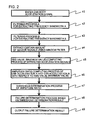
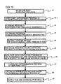
- Fig. 2 is a flow showing the defect detecting/determining process of the defect detection system 20. The flow from input of the car body acceleration signal to the output of the defect detection result will be described with reference to the drawing. In Fig. 2 , “s" refers to steps.
- the defect detection system 20 receives input (s1) of the car body lateral vibration acceleration signal 22a from the car body acceleration detector 11 in the filtering sections A 12 and B 13, executes a filtering process A for extracting a certain frequency bandwidth A from the signal (s2), executes a filtering process B for extracting a certain frequency bandwidth B from the signal (s3), and executes a process for filtering a certain amount of signal counts using a window filter (s4).
- the defect detection system 20 executes an RMS value computing process to the car body lateral vibration acceleration signals 23a and 24a extracted via the filtering sections 12A and 13A in the RMS computing sections A14 and B15 (s5).
- the RMS value is the square root of an arithmetic average of the squares of original values from a group of signals as object, which shows one index of the magnitude of variation.
- the defect detection system 20 executes calculation in the amplitude ratio computing section 16 (S6) of the amplitude ratio of the RMS value of the car body lateral vibration acceleration signal 23a and the RMS value of the car body lateral vibration acceleration signal 24a based on the RMS values 25a and 26a of the car body lateral vibration acceleration signals computed via the RMS computing sections A14 and B15, and outputs an amplitude ratio computing signal 27a.
- the defect detection system 20 executes a threshold determination process in the threshold determination section 17 for the amplitude ratio signal 27a based on the amplitude ratio computed in the amplitude ratio computing section 16 and the threshold determined in advance (s7) , and outputs a threshold determination process signal 28a.
- the predetermined threshold set in advance refers to a defect determination threshold set to determine whether the amplitude ratio falls within a normal range or within a defect range. The actual examples of which will be described in detail later.
- the defect detection system 20 determines whether defect has occurred or not based on the threshold determination result (threshold determination process signal 28a) with respect to the amplitude ratio signal 27a in the defect detection section 18 (s8), and outputs a defect determination process signal 29a. Then, the determination result output section 19 outputs a defect determination result based on the defect determination process signal 29a (s9).
- the defect determination result is notified via a means not shown for outputting an alarm signal indicating the defect determination result to a device for confirming defect disposed at a location where the defect can be confirmed within the car 7, that is, in the driver's cabin of the car body 6 where the driver can easily confirm the defect.
- the notice of defect can be performed for example by displaying a notice on a display unit or by outputting an alarm sound via a speaker disposed on an apparatus.
- Fig. 3 shows an example of application of filtering processing and application of a widow filter to the aforementioned car body lateral vibration acceleration signal (waveform) 22a and an example of computing the amplitude ratio of the RMS value, which corresponds to processes s2 through s6 of Fig. 2 .
- a filter A 42 of the filtering section A 12 and a filter B 43 of the filtering section B 13 are bandpass filters each having certain frequency bandwidths for extracting a car body lateral vibration acceleration A 51 (corresponding to the car body lateral vibration acceleration signal 23a of Fig. 1 ) and a car body lateral vibration acceleration B 52 (corresponding to the car body lateral vibration acceleration signal 24a of Fig. 1 ) from a car body lateral vibration acceleration 41 (corresponding to the car body lateral vibration acceleration signal 22a of Fig. 1 ).
- the filtering section constituting the filtering means for extracting two varied frequency band components from the car body vibration acceleration signal is composed of at least two filters. These filters are composed of bandpass filters having different frequency band regions (frequency bandwidths).
- the frequency band uses bandpass filters having frequency bands with portions thereof overlapped, but is not restricted thereto.
- Window filters 50 and 50 are used in the subsequent stage of bandpass filters A 42 and B 43 of filtering sections A 12 and B 13.
- the window filter 50 has a certain length (time) , and within that length, car body lateral vibration acceleration RMS values A 53 and B 54 are computed based on the car body lateral vibration acceleration signals A 51 and B 52 having certain frequency bandwidths.
- An RMS value amplitude ratio 55 is computed as a ratio (Y/X) of a car body lateral vibration acceleration RMS value B 54 (Y, for example) with respect to a car body lateral vibration acceleration RMS value A 53 (X, for example). Further, the acceleration signal within the window filter 50 is varied momentarily, so that the car body lateral vibration acceleration RMS value A 53, the car body lateral vibration acceleration RMS value B 54 and the RMS value amplitude ratio 55 are varied momentarily without taking fixed values.
- the RMS value is taken as an example, but the same process can be applied for computing the maximum value, wherein if a maximum value of amplitude ratio is to be computed, the maximum value is computed based on the absolute values of car body lateral vibration acceleration signal A 51 and car body lateral vibration acceleration signal B 52 to obtain the amplitude ratio.
- the system is equipped with a computing section for computing the RMS value or the maximum value of the acceleration signal extracted via the window filter.
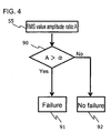
- Fig. 4 shows an example of a threshold determination process and a defect determination process with respect to the RMS value amplitude ratio 55, corresponding to processes s7 through s9 of Fig. 2 .
- a determination section 90 compares and determines the magnitude relation of the RMS value amplitude ratio 55 (RMS value amplitude ratio: A) and a given threshold ⁇ .
- the threshold ⁇ is computed in advance via a driving test or an analysis result the amplitude ratio of vibration of a sound car, and the value is set based on the computed result.
- This threshold ⁇ is stored in a storage unit 10 composed for example of a RAM.
- the storage unit can be composed of a memory with only a small capacity for storing only the threshold, and defect can be detected easily since setting of threshold levels corresponding to each driving speed pattern, which was required in the prior art, is not required. Since the capacity of the storage means for storing the threshold can be small, defect detection can be performed easily with high accuracy via a simple system configuration.
- the determination section 90 determines that there is "no defect” 92 when the RMS value amplitude ratio 55 is smaller than the predetermined threshold ⁇ , and determines that there is "defect” 91 when the RMS value amplitude ratio 55 is greater than the predetermined threshold ⁇ .
- Fig. 4 takes the RMS value amplitude ratio 55 as an example, but a similar determination process can be applied using the maximum amplitude ratio. In that case, a predetermined value must be set as the threshold.
- Figs. 5(a) and 5(b) show a general traveling speed 44 (including the car body acceleration) and a time history waveform of the car body acceleration 45 (including the vibration waveform/ impulse disturbance 4 6 when passing a branched section) , in which the horizontal axis represents time [S] and the vertical axis represents traveling speed [km/h] or the horizontal axis represents time [S] and the vertical axis represents car body acceleration [m/s 2 ] .
- car 7 is accelerated from a stopped state (0 km/h) to a constant speed section, and then the car is decelerated from the constant speed section to the deceleration section and stopped.
- the car body lateral vibration acceleration 45 of Fig. 5 (b) depends on the traveling speed 44 of Fig. 5(a) . Therefore, the car body lateral vibration acceleration 45 is gradually increased during acceleration, takes a vibration level corresponding to the traveling speed 44 in the constant speed section, and is gradually reduced during deceleration.
- an impulse-like vibration waveform 46 occurs when the car passes a branched section or a junction (impulse disturbance when passing a branch).
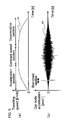
- Fig. 6 (a), 6 (b) and 6 (c) are waveforms showing the traveling speed 44', the car body lateral vibration acceleration 49 and the power spectral densities 60, 63 and 64 thereof.
- the car body lateral vibration acceleration 49 in Fig. 6 (b) assumes that the abnormal vibration caused in an abnormal vibration occurrence section is the abnormal vibration caused by the defect of a bogie component or the like.
- the power spectral densities (hereinafter abbreviated as PSD) 60, 63 and 64 are computed at a time interval 60' of the car body lateral vibration acceleration 49 including the branched section and time intervals 63' and 64' where abnormal vibration occurs.
- PSD 60 includes a peak that rises instantly when the car passes a branch, and the PSD 63 includes a peak caused by the detect of a bogie component or the like.
- the overall value of PSD 64 is small since the traveling speed of the car is small (slow).
- filters A 42' and B 43' applied for computing the amplitude ratio are described.
- the filter A42' uses a bandpass filter to set up a cutoff frequency f A1 and a cutoff frequency f A2 having a certain frequency bandwidth from the peak frequency at the center.
- the filter B 43' uses a bandpass filter to set up a cutoff frequency f B1 and a cutoff frequency f B2 having a frequency bandwith including all the peak frequencies.
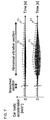
- Fig. 7 shows a time history waveform and RMS values extracted via the filters A 42' and B 43'.
- the car body lateral vibration acceleration 70 is a time history waveform extracted via the filter A 42'
- the RMS values 72 are obtained by applying the RMS value calculation to the car body lateral vibration acceleration 70.
- the car body lateral vibration acceleration 71 is a time history waveform extracted via the filter B 43'
- the RMS values 73 are obtained by applying the RMS value calculation to the car body lateral vibration acceleration 71.
- the abnormal vibration section only the vibration components caused via the defect of a bogie component are extracted in the car body lateral vibration acceleration 71, and the vibration levels of the car body lateral vibration acceleration 70 and the car body lateral vibration acceleration 71 are reduced accompanying the acceleration and deceleration of the car.
- the RMS values 72 and 73 are also reduced in the same manner.
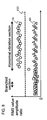
- Fig. 8 shows an example of applying the RMS value amplitude ratios with respect to the RMS values of Fig. 7 .
- the amplitude ratios 74 represent the ratio (Y/X) of the RMS values 73 (Y, for example) with respect to the RMS values 72 (X, for example).
- the RMS values 72 and 73 are substantially equal, and the amplitude ratio is not different from the ratios in the other sections.
- the RMS value 73 is calculated as a greater value than the RMS value 72, so the amplitude ratio 74 is calculated as a high value corresponding to the ratio of the RMS values 73 and 72.
- the traveling speed is small, the RMS values 73 and 72 are also small, so that the amplitude ratio 74 will not become small and the speed dependency can be eliminated.
- a threshold 150 for example, defect of only the vibration waveform within the abnormal vibration section can be detected.
- the amplitude ratio 66 has been applied to the car body lateral acceleration 45 (refer to Fig. 5 ).
- Figs. 9 (a), 9 (b) and 9 (c) show waveforms of traveling speed 44', car body lateral vibration acceleration 47 and power spectral densities 60 through 62 thereof.
- the abnormal vibration generated in the abnormal vibration generation section assumes a meandering vibration waveform that occurs at a certain speed or higher.
- the PSD 60, 61 and 62 (refer to Fig. 9c ) are calculated from the car body lateral vibration acceleration 47 at a time interval 60' including the branched section, a time interval 61' of a section where abnormal vibration occurs, and a time interval 62' of a section where the car speed is slow, wherein the PSD 60 has a peak that rises instantly when the car passes a branch, and the PSD 61 has a peak that rises by the meandering vibration characteristics occurring at a certain speed or higher.
- the PSD 62 corresponds to a section where no abnormal vibration occurs and where traveling speed is slow, so that the PSD is small.
- filters A 42' and B 43' applied for computing the amplitude ratio are described.
- the filter A42' uses a bandpass filter to set up a cutoff frequency f A1 and a cutoff frequency f A2 having a certain frequency bandwidth from the peak frequency set as center.
- the filter B 43' uses a bandpass filter to set up a cutoff frequency f B1 and a cutoff frequency f B2 having a frequency bandwith including all the peak frequencies.
- Fig. 10 shows a time history waveform and an RMS value extracted via the filters A 42' and B 43'.
- the car body lateral vibration acceleration 75 is a time history waveform extracted via the filter A 42', and the RMS value 77 is obtained by applying the RMS value calculation to the car body lateral vibration acceleration 75.
- the car body lateral vibration acceleration 76 is a time history waveform extracted via the filter B 43' , and the RMS value 78 is obtained by applying the RMS value calculation to the car body lateral vibration acceleration 76.
- the abnormal vibration section only the meandering vibration component is extracted in the car body lateral vibration acceleration 76, and the same applies for the RMS value 78.
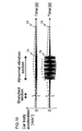
- Fig. 11 shows an example of applying the RMS value amplitude ratio with respect to the RMS value of Fig. 9 .
- the amplitude ratios 79 represents the ratio (Y/X) of the RMS values 78 (Y, for example) with respect to the RMS values 77 (X, for example).
- the RMS values 75 and 76 are substantially equal, and the amplitude ratio 79 is not different from the ratios in the other sections.
- the RMS value 78 is computed as a greater value than the RMS value 77, so that the amplitude ratio 79 is calculated as a high value corresponding to the ratio of the RMS values 77 and 78 .
- a threshold 150 for example, only the vibration wave form within the abnormal vibration section can be detected as a defect.
- the amplitude ratio 66 has been applied to the car body lateral acceleration 45.
- two car body acceleration amplitude ratios of different frequency bands extracted from a single car body acceleration are used to execute a threshold determination process with respect to a predetermined threshold, according to which the influence of traveling speed dependency can be eliminated, and since there is no need to set up thresholds corresponding to respective traveling speed patterns, the capacity of the storage unit for storing the threshold can be made small and defect can be detected with high accuracy via a simple system configuration.
- Fig. 12 shows a flow of the threshold determination process and the defect determination process of a state monitoring apparatus of a railway car according to embodiment 2 of the present invention
- Fig. 13 shows an application example of the threshold determination of embodiment 2 of the present invention with respect to the amplitude ratio.
- Embodiment 2 adds a threshold determination process corresponding to the number of exceedance of the amplitude ratio in the threshold determination process of embodiment 1.
- the present embodiment adds a determination section 93 in the determination flow to embodiment 1 of Fig. 4 as shown in Fig. 12 .
- the determination section 93 observes the number of times N in which the RMS value amplitude ratio 55 exceeding the threshold ⁇ 81 of a certain amplitude ratio in the determination section 90 has exceeded the threshold ⁇ (threshold with respect to the amplitude ratio level) of the amplitude ratio within a certain time, and compares the same with a threshold ⁇ (threshold with respect to a number of exceedance of level ⁇ of the amplitude ratio) of a predetermined number of exceedance of a threshold.
- the determination section 93 can observe an excess time T of amplitude ratio with respect to threshold ⁇ in which the RMS value amplitude ratio 55 exceeds the threshold ⁇ of a certain amplitude ratio in the determination section 90, and compares the same with a predetermined threshold ⁇ of the threshold excess time.
- the excess time T of the amplitude ratio with respect to threshold ⁇ is smaller than a certain threshold ⁇ of threshold excess time, it is determined that there is "no defect", and if the excess time T of the amplitude ratio with respect to threshold ⁇ is greater than a certain threshold ⁇ of a threshold excess time, it is determined that there is "defect".
- the number of the RMS value amplitude ratio 83 is greater than a predetermined threshold (when assuming that the threshold is 3) within a predetermined time 82 so that it is determined that there is "defect”
- the number 84 of the RMS value amplitude ratio is smaller than a predetermined value (when assuming that the threshold is 3) so that it is determined that there is "no defect”.
- the present embodiment by adding a threshold determination process function for determining whether the values have exceeded the threshold for a predetermined number of times or greater within the predetermined time in addition to the threshold determination process with respect to the level of the RMS value amplitude ratio 55, it becomes possible to improve the detection accuracy even when the amplitude ratio has exceeded the threshold instantly due to noise or disturbance, for example.
- Fig. 14 corresponds to the system configuration diagram of the state monitoring apparatus of a railway car according to embodiment 1 of the present invention
- Fig. 15 corresponds to the defect detection/determination process flow of the state monitoring apparatus of a railway car according to embodiment 1 of the present invention
- Fig. 16 shows the filter application example of embodiment 1 of the present invention, wherein according to embodiment 3, a car speed information is newly added and a function for automatically changing a filter coefficient of filtering of the defect detection system is also added with respect to embodiment 1.
- the present embodiment has added to embodiment 1 of Fig. 1 in the system configuration a car speed detector 101 for detecting the car speed via a car information system disposed on the car on the car 6, and adds to the defect detection system 20 a filter conversion processing section 102 for automatically changing the filter coefficients such as the cutoff frequencies of the filtering sections A 12 and B 13 based on the traveling speed signal 110a from the car speed detector 101.
- the filter conversion processing section 102 receives input of the traveling speed signal 110a output from the car speed detector 101 disposed on the car 7 and outputs a filter conversion signal 111a to the filtering section A 13 and the filtering section B 14.
- the filtering section A 13 and the filtering section B 14 applies a bandpass filter using a cutoff frequency assigned by the filter conversion signal 111a to the car body lateral vibration acceleration signal 22a.
- the defect detection/determination process flow executes after input of the car body lateral vibration acceleration signal 22a from the car body acceleration detector 11 (s1) a coefficient conversion process (s2-1) regarding the cutoff frequencies or the like of the filtering process A 42 and the filtering process B 43 based on the car traveling speed.
- the bandpass filter 120 is automatically changed to bandpass filter 120' to correspond to the peak frequencies of the PSD 121 and PSD121' .
- the frequency band of the bandpass filter is shifted from fc1 - fc2 to fD1 - fD2, and the frequency band is not overlapped.
- the present embodiment illustrated an example in which the filtering processes A 42 and B 43 are applied to the car body lateral vibration acceleration, but the same can be applied to a car body lengthwise acceleration or a car body vertical acceleration.
- a filter by adding a filter conversion processing section 102 for automatically changing the filter coefficient such as the cutoff frequencies of the filtering sections A 12 and B 13 based on the traveling speed of the car, for example, a filter can be constantly applied to the vibration component having its frequency varied due to the wheel rotation frequency, according to which the detection accuracy can be improved.
- FIG. 17 shows a system configuration diagram of a state monitoring apparatus of a railway car according to embodiment 4
- Fig. 18 shows a defect detection/determination process flow of the state monitoring apparatus of the railway car according to embodiment 4
- Fig. 19 shows the filtering process, the RMS value computing process and the amplitude ratio computing process according to embodiment 4 of the present invention, wherein embodiment 4 adds to embodiment 1 an amplitude ratio computing process of two vibration accelerations in different directions (such as the lateral vibration acceleration and the vertical vibration acceleration).
- the present embodiment adds to the system configuration of embodiment 1 shown in Fig. 1 a voltage 21a' , a car body acceleration detector 11' and a car body vertical vibration acceleration signal 22a'.
- voltages 21a and 21a' are of different directions, which are respectively detected in the car body acceleration detectors 11 and 11' as a car body lateral vibration acceleration signal 22a and a car body vertical vibration acceleration signal 22a' , for example, and the car body lateral vibration acceleration signal 22a is sent to the filtering section A 12 and the car body vertical vibration acceleration signal 22a' is sent to the filtering section B 13.
- a filtering process A 42 is performed to the car body lateral vibration acceleration signal 22a (s2-3) and a filtering process B 43 is performed to the car body lateral vibration acceleration signal 22a' (s3-3).
- the car body lateral vibration acceleration 41 is applied to the filter A 42 by which an RMS value 53 (X, for example) is extracted, and the car body vertical vibration acceleration 41' is applied to the filter B 43 by which an RMS value 54 (Y, for example) is extracted, according to which the amplitude ratio (Y/X) is calculated.
- the amplitude ratio can be computed by performing control to automatically change the cutoff frequency of the bandpass filter in response to the change of condition of car speed, for example.
- the amplitude ratio was computed for the respective RMS values of the car body lateral vibration acceleration and the car body vertical vibration acceleration, but the same can be computed for the respective RMS values of the car body lateral vibration acceleration and the car body lengthwise vibration acceleration, or the car body lengthwise vibration acceleration and the car body vertical vibration acceleration.
- the present embodiment by computing the amplitude ratio regarding the RMS values of two vibration accelerations whose measurement directions differ, it becomes possible to detect the balance of vibration components in different directions and to detect the defect by determining that the balance is not normal.
- FIG. 20 is a system configuration of a state monitoring apparatus of a railway car regarding a power supply car 200 equipped with a facility for obtaining electric power by driving a power generator 202 via the driving force of an engine 201, wherein embodiment 5 differs from embodiment 3 in that the present embodiment assumes a case in which the vibration source is on the car, caused by the defect of the engine 201 or the power generator 202 or other reasons related to the engine 201 or the power generator 202.
- the power generator 202 is disposed above the engine 201.
- the present embodiment can be applied not only to the engine and the power generator disposed on the car body but to cases in which the vibration is caused by car-mounted equipments such as a bogie motor, a drive unit or a journal bearing.
- the present embodiment illustrates an example in which the filtering processes A 42 and B 43 are applied to the car body lateral vibration acceleration, but the present embodiment can similarly be applied to the car body lengthwise acceleration or the car body vertical acceleration.
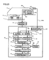
- the present embodiment adds to the system configuration of embodiment 3 shown in Fig. 14 a power supply car 200 equipped with a facility for obtaining power by driving a power generator 202 via the driving force of an engine 201, and provides to the filter conversion processing section 102 a command signal 220a from a command unit 203 for controlling the number of rotations of the engine 201.
- the filter conversion processing section 102 receives input of a traveling speed signal 110a output from a car speed detector 101 disposed on the power supply car 200, and outputs a filter conversion signal 111a to the filtering sections A 13 and B 14.
- the filtering sections A 13 and B 14 apply a bandpass filters using cutoff frequencies assigned by the filter conversion signal 111a to the car body lateral vibration acceleration signal 22a.
- the defect detection/determination process flow shown in Fig. 21 executes a coefficient conversion process of the filtering process A 42 and the filtering process B 43 based on a command signal 20a (s2-4) after input of the car body lateral vibration acceleration signal 22a from the car body acceleration detector 11 (s1).
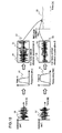
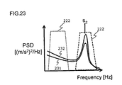
- the present embodiment illustrates in Fig. 22 a filter application example in which when a command signal s 1 is changed in a discontinuous manner to command signal s 2 , even if the PSD 221 is changed via the command signal to PSD 221' , the bandpass filter 220 is automatically changed to a bandpass filter 220' in response to the peak frequencies of PSD 221 and PSD 221'.
- the amplitude ratio computes a ratio (Y/X) of the RMS value of the car body lateral vibration acceleration extracted via the bandpass filters 220 and 220' (Y, for example) to the RMS value of the car body lateral vibration acceleration extracted via the bandpass filter 222 (X, for example), and thresholds regarding the respective command signals s 1 and s 2 are selected in advance, so that switching can be performed to correspond to the states of command signals s 1 and s 2 .
- the amplitude ratio is increased, so that defect can be detected by comparing the same with a threshold determined in advance.
- the present embodiment adds a filter conversion processing section 102 capable of automatically changing the filter coefficient such as the cutoff frequencies of the filtering sections A 12 and B 13 based on the traveling speed of the car, so that the filter can be constantly applied to a vibration component having its frequencies varied due for example to the wheel rotation frequency, and thus, the detection accuracy can be improved.
- the meandering vibration of the railway car or the defect of suspensions such as the air spring or the lateral vibration damper can be monitored accurately and reliably.
- the present embodiments do not require setting of threshold levels corresponding to various traveling speed patterns as in the prior art to monitor the defect, so that the system configuration can be simplified, and the influence of traveling speed of the car can be eliminated without increasing the storage capacity for storing thresholds.
Landscapes
- Engineering & Computer Science (AREA)
- Mechanical Engineering (AREA)
- Health & Medical Sciences (AREA)
- Biomedical Technology (AREA)
- General Health & Medical Sciences (AREA)
- Physics & Mathematics (AREA)
- Acoustics & Sound (AREA)
- Electromagnetism (AREA)
- Electric Propulsion And Braking For Vehicles (AREA)
- Measurement Of Mechanical Vibrations Or Ultrasonic Waves (AREA)
Abstract
Description
- The present invention relates to a state monitoring apparatus and a state monitoring method of a railway car for monitoring a defective state of a railway car traveling on tracks, especially the defect of tracks and cars, and a railway car.
- The prior art state monitoring apparatus (defect detection system) of a railway car teaches detecting a vibration acceleration in a perpendicular direction via a sensor disposed on a floor of a car body above a spring device of the car, detecting a maximum value of the absolute value within a predetermined frequency range of the detected vibration acceleration, comparing the maximum value with threshold limit values (hereinafter abbreviated as threshold) stored in response to respective traveling speed patterns, wherein when the maximum value of the absolute value of the vibration acceleration in the perpendicular direction within the frequency range exceeds a threshold limit value corresponding to the traveling speed detected during driving of the car, it is determined that the railway car has derailed (refer for example to
patent document 1;WO 00/09379 - However, the disclosed prior art is aimed at detecting derailing of the railway car, and it does not consider detecting any defect of the car prior to detecting derailing. Further, according to the prior art, the threshold values corresponding to the traveling speeds are values obtained by driving the cars in the respective tracks according to respective driving patterns. In other words, the railway car must be driven along predetermined tracks while changing the traveling speed thereof to acquire the threshold limit values of the perpendicular acceleration (threshold) determined for each of the predetermined speeds as thresholds for detecting derailing, which requires time, and the storage means for storing the thresholds must have a large capacity, and the system becomes complex since traveling speed is required for selecting the threshold. A predetermined threshold refers to a defect detection reference value for determining the state of the railway car, that is, the defect of the railway car.
- In consideration of the problems of the prior art mentioned above, the present invention aims at solving the problems of the prior art by providing a state monitoring apparatus and a state monitoring method of a railway car capable of detecting any defect to be set before a serious defect occurs, without requiring thresholds for respective traveling speed patterns, and a railway car.
- In order to achieve the above object, the present invention provides a railway car comprising a vibration detector for detecting a vibration of the railway car, and a defect detection system for detecting defect of the railway car using a signal output from the vibration detector, wherein the vibration detector includes a vibration detection means for detecting the vibration of the railway car from a vibration acceleration of the car body, and the defect detection system includes a filtering means for detecting two different frequency band components based on the car body vibration acceleration from the vibration detectionmeans, an amplitude ratio computingmeans for computing an amplitude ratio of two or more car body vibration accelerations detected via the filtering means, and a defect determination processing means for determining defect based on the result of the amplitude ratio computing means.
- Further, the railway car characterizes in that the amplitude ratio computing means of the defect detection system comprises a window filer for extracting a fixed amount of acceleration signals from the car body vibration acceleration, and a computing section for computing an RMS (root mean square) value of the car body acceleration signals extracted via the window filter or a maximum value thereof, wherein the filtering means includes a bandpass filter.
- Further, the railway car comprises a defect determination processing means for determining whether the amplitude ratio has exceeded a threshold of a predetermined number of times within a predetermined time.
- According further to the railway car, the defect detection system is equipped with a filtering means for detecting three or more frequency band components from the car body vibration acceleration detected via the vibration detecting means, an amplitude ratio computingmeans for computing the amplitude ratio from a combination of three or more of said car body accelerations detected via the filtering means, and a defect determination means for determining defect from the result of the amplitude ratio computing means.
- Further, the railway car is equipped with a traveling speed detector for detecting the traveling speed, and a filter coefficient conversion unit for automatically setting a cutoff frequency of the filtering means of the detect detection system using signals detected via the traveling speed detector.
- According to the present invention, the defect of the state of a railway car can be monitored accurately and reliably.
- Further, the monitoring of the defect can be performed without determining thresholds corresponding to respective traveling speed patterns as according to the prior art.
-
-
FIG. 1 is a system con figuration diagram of a state monitoring apparatus of a railway car according to one preferred embodiment (embodiment 1) of the present invention; -
Fig. 2 is a flow chart of the defect detection/determination process showing the flow of signal processing of the defect detection system according toFig. 1 ; -
Fig. 3 illustrates an example of applying a window filter to the signal of the state monitoring apparatus and an example of computing an amplitude ratio of the RMS value in a railway car according to the present invention; -
Fig. 4 is a view showing a threshold determination process and a defect determination process according to one embodiment of the state monitoring apparatus of a railway car according to the present invention; -
Figs. 5 (a) and 5 (b) show the traveling speed of a car and the time history waveform of a car body lateral vibration acceleration including an impulse vibration when the car passes a branch; -
Figs. 6 (a) , 6 (b) and 6 (c) are views showing the time history waveform of a car body lateral vibration acceleration including an abnormal vibration caused by the failure of a bogie component or the like, and power spectral densities; -
Fig. 7 is a view showing the time history waveform of the car body lateral vibration acceleration including an abnormal vibration caused by the failure of a bogie component or the like being subjected to filtering process, and the RMS values; -
Fig. 8 is a view showing an example of application of the RMS value amplitude ratio to the RMS values ofFig. 7 ; -
Figs. 9 (a) , 9 (b) and 9 (c) are views showing the traveling speed of the car, the time history waveform of a car body lateral vibration acceleration including an abnormal vibration caused by meandering or the like, and power spectral densities; -
Fig. 10 shows the time history waveform of the car body lateral vibration acceleration including an abnormal vibration caused by meandering or the like being subjected to filtering process, and the RMS values; -
Fig. 11 shows an example of application of the RMS value amplitude ratio to the RMS values ofFig. 10 ; -
Fig. 12 shows a threshold determination process and a defect determination process of a state monitoring apparatus of a railway car according to yet another embodiment (embodiment 2) of the present invention; -
Fig. 13 shows an example of application of the RMS value amplitude ratio to the vibration waveform ofFig. 12 ; -
Fig. 14 is a system configuration diagram of a state monitoring apparatus of a railway car showing yet another embodiment (embodiment 3) of the present invention; -
Fig. 15 is a flow chart of the defect detection/determination process illustrating the flow of signal processing of the defect detection system according toFig. 14 ; -
Fig. 16 is a view showing a filter application example corresponding to traveling speed conditions; -
Fig. 17 is a system configuration diagram of a state monitoring apparatus of a railway car showing yet another embodiment (embodiment 4) of the present invention; -
Fig. 18 is a flow chart of the defect detection/determination process illustrating the flow of signal processing of the defect detection system according toFig. 17 ; -
Fig. 19 is a view showing an example of applying a window filter to the signal of the state monitoring apparatus and an example of computing an amplitude ratio of the RMS value in a railway car shown inFig. 17 ; -
Fig. 20 is a system configuration diagram of a state monitoring apparatus of a railway car showing yet another embodiment (embodiment 5) of the present invention; -
Fig. 21 is a flow chart of the defect detection/determination process illustrating the flow of signal processing of the defect detection system according toFig. 20 ; -
Figs. 22(a) and 22(b) are views showing an example of application of filters corresponding to command signals; and -
Fig. 23 is a view showing an example of application of filters corresponding to command signals, wherein a normal state and an abnormal state are illustrated. - Now, the preferred embodiments of the present invention will be described in detail with reference to the drawings. In the drawings, the components having common functions are denoted by the same reference numbers, and detailed descriptions thereof are omitted.
-
Fig. 1 is a system configuration diagram showing an example of configuration of a state monitoring apparatus of a railway car according to a preferred embodiment (embodiment 1) of the present invention. - In
Fig. 1 , acar 7 driven on tracks (railway tracks) 1 is composed of acar body 6 and abogie 5. Thecar body 6 is mounted on bogies 5 (only one bogie is shown) viaair springs 4. Thebogie 5 is composed of abogie frame 3 andwheelsets 2. Anaxle box 9 as bearing housing for thewheelset 2 is attached via anaxle spring 8 to thebogie frame 3. Thewheelsets 2 are capable of performing rotary motion. - An acceleration meter can be disposed on the
car body 6, thebogie 5 or other components, but in the present embodiment, the acceleration meter is disposed on thecar body 6. - Furthermore, the direction of acceleration can be in any of the following directions, front and rear (lengthwise) sides in the horizontal direction, left and right (lateral) sides in the horizontal direction, or perpendicular direction, but in the present embodiment, the acceleration in the left and right (lateral) sides in the horizontal direction is described.
- The present invention can be equipped with a filtering section for detecting two or more different frequency band components, but in the present embodiment, the railway car is equipped with a filtering section for detecting two different frequency band components.
- Moreover, the present invention can be equipped with a pluralityof vibrationdetectors, but in the present embodiments, a single vibration detector is disposed.
- A car
body acceleration meter 100 is disposed above a floor surface of thecar body 6 of thecar 7 for measuring a lateral vibration acceleration of thecar body 6. The carbody acceleration meter 100 is equipped with a carbody acceleration detector 11 for detecting avoltage 21a of the carbody acceleration meter 100. Thevoltage 21a of the carbody acceleration meter 100 is detected as a car body lateralvibration acceleration signal 22a via the carbody acceleration detector 11. In other words, the carbody acceleration detector 11 including the carbody acceleration meter 100 constitutes a vibration detecting means for detecting the vibration of thecar 7. - A
defect detection system 20 for detecting the defect of thecar 7 is electrically connected to the carbody acceleration detector 11 and receives a car body lateralvibration acceleration signal 22a from the carbody acceleration detector 11, based on which the defect of the car is detected. - In other words, the system is a defect detection system for detecting the defect of a railway car based on the car body lateral vibration acceleration signal including the vibration information of the car body of the railway car, wherein the actual example of the system is composed of a
filtering section A 12 and afiltering section B 13 connected to the carbody acceleration detector 11 and receiving car body lateralvibration acceleration signals 22a, RMS valuecomputing sections A 14 andB 15 for receiving a car body lateralvibration acceleration signal 23a and a car body lateralvibration acceleration signal 24a of varied frequency bands extracted via these filtering sections, an amplituderatio computing section 16 for computing the amplitude ratio of anRMS signal 25a and anRMS signal 26a computed via the RMS value computing sections and outputting anamplitude ratio signal 27a, athreshold determination section 17 for receiving theamplitude ratio signal 27a and athreshold signal 30a stored in advance in athreshold storage section 10 to execute a threshold determination process and outputting a thresholddetermination process signal 28a, adefect determination section 18 for receiving the thresholddetermination process signal 28a to execute a defect determination process and outputting a defectdetermination process signal 29a, and a determinationresult output section 19 for receiving the defectdetermination process signal 29a and outputting the determination result. Thedefect detection system 20 is disposed on thecar body 6, but the installation position can be any position as long as the determination result can be confirmed. When performing processing via the RMS value computing sections A14 and B15, the car body lateral vibration acceleration is extracted for a predetermined time via a window filter (described in detail later) from the signals having passed through thefiltering sections A 12 andB 13. - Now, the amplitude
ratio computing section 16 of thedefect detection system 20 constitutes an amplitude ratio computing means for computing an amplitude ratio between the car body lateralvibration acceleration signal 23a and the car bodylateral vibration acceleration 24a, based on theRMS signal 25a from the RMS value computing section A14 and theRMS signal 26a from the RMS value computing section B15. Thethreshold determination section 17 constitutes a threshold determination process means for determining the above-mentioned amplitude ratio and thethreshold signal 30a stored in advance in thethreshold storage section 10 based on theamplitude ratio signal 27a from the amplituderatio computing section 16, and thedefect determination section 18 and the determinationresult output section 19 constitutes a defect determination process means for determining defect from the result obtained via the thresholddetermination process signal 28a of thethreshold determination section 17 and the defectdetermination process signal 29a of thedefect determination section 18. - Regarding the threshold determination process via the
threshold determination section 17, a storage means is disposed for storing a threshold (described in detail later) for performing comparison with the amplitude ratio signal obtained via the amplitude ratio computing process. Now, the value of RMS (root mean square) is a square root of an arithmetic average of the squares of original values, and the calculation process thereof is well known, so it will not be described in detail. - Next, with reference to
Figs. 2 through 4 , the process flow of the operation of adefect detection system 20 in a state monitoring apparatus of a railway car according to one preferred embodiment of the present invention, including a filtering process, an RMS value computing process, an amplitude ratio computing process, a threshold determination process and a defect determination process, will be described in detail. -
Fig. 2 is a flow showing the defect detecting/determining process of thedefect detection system 20. The flow from input of the car body acceleration signal to the output of the defect detection result will be described with reference to the drawing. InFig. 2 , "s" refers to steps. - At first, the
defect detection system 20 receives input (s1) of the car body lateralvibration acceleration signal 22a from the carbody acceleration detector 11 in the filtering sections A 12 andB 13, executes a filtering process A for extracting a certain frequency bandwidth A from the signal (s2), executes a filtering process B for extracting a certain frequency bandwidth B from the signal (s3), and executes a process for filtering a certain amount of signal counts using a window filter (s4). - Next, the
defect detection system 20 executes an RMS value computing process to the car body lateralvibration acceleration signals - Further, the
defect detection system 20 executes calculation in the amplitude ratio computing section 16 (S6) of the amplitude ratio of the RMS value of the car body lateralvibration acceleration signal 23a and the RMS value of the car body lateralvibration acceleration signal 24a based on the RMS values 25a and 26a of the car body lateral vibration acceleration signals computed via the RMS computing sections A14 and B15, and outputs an amplituderatio computing signal 27a. - Next, the
defect detection system 20 executes a threshold determination process in thethreshold determination section 17 for theamplitude ratio signal 27a based on the amplitude ratio computed in the amplituderatio computing section 16 and the threshold determined in advance (s7) , and outputs a thresholddetermination process signal 28a. Now, the predetermined threshold set in advance refers to a defect determination threshold set to determine whether the amplitude ratio falls within a normal range or within a defect range. The actual examples of which will be described in detail later. - Finally, the
defect detection system 20 determines whether defect has occurred or not based on the threshold determination result (thresholddetermination process signal 28a) with respect to theamplitude ratio signal 27a in the defect detection section 18 (s8), and outputs a defectdetermination process signal 29a. Then, the determinationresult output section 19 outputs a defect determination result based on the defectdetermination process signal 29a (s9). The defect determination result is notified via a means not shown for outputting an alarm signal indicating the defect determination result to a device for confirming defect disposed at a location where the defect can be confirmed within thecar 7, that is, in the driver's cabin of thecar body 6 where the driver can easily confirm the defect. The notice of defect can be performed for example by displaying a notice on a display unit or by outputting an alarm sound via a speaker disposed on an apparatus. -
Fig. 3 shows an example of application of filtering processing and application of a widow filter to the aforementioned car body lateral vibration acceleration signal (waveform) 22a and an example of computing the amplitude ratio of the RMS value, which corresponds to processes s2 through s6 ofFig. 2 . - A
filter A 42 of thefiltering section A 12 and afilter B 43 of thefiltering section B 13 are bandpass filters each having certain frequency bandwidths for extracting a car body lateral vibration acceleration A 51 (corresponding to the car body lateralvibration acceleration signal 23a ofFig. 1 ) and a car body lateral vibration acceleration B 52 (corresponding to the car body lateralvibration acceleration signal 24a ofFig. 1 ) from a car body lateral vibration acceleration 41 (corresponding to the car body lateralvibration acceleration signal 22a ofFig. 1 ). - In other words, according to the present embodiment, the filtering section constituting the filtering means for extracting two varied frequency band components from the car body vibration acceleration signal is composed of at least two filters. These filters are composed of bandpass filters having different frequency band regions (frequency bandwidths). In the present embodiment, the frequency band uses bandpass filters having frequency bands with portions thereof overlapped, but is not restricted thereto. Window filters 50 and 50 are used in the subsequent stage of bandpass filters A 42 and
B 43 of filtering sections A 12 andB 13. - The
window filter 50 has a certain length (time) , and within that length, car body lateral vibration acceleration RMS values A 53 andB 54 are computed based on the car body lateral vibration acceleration signals A 51 andB 52 having certain frequency bandwidths. - An RMS
value amplitude ratio 55 is computed as a ratio (Y/X) of a car body lateral vibration acceleration RMS value B 54 (Y, for example) with respect to a car body lateral vibration acceleration RMS value A 53 (X, for example). Further, the acceleration signal within thewindow filter 50 is varied momentarily, so that the car body lateral vibration accelerationRMS value A 53, the car body lateral vibration accelerationRMS value B 54 and the RMSvalue amplitude ratio 55 are varied momentarily without taking fixed values. - Here, the RMS value is taken as an example, but the same process can be applied for computing the maximum value, wherein if a maximum value of amplitude ratio is to be computed, the maximum value is computed based on the absolute values of car body lateral vibration
acceleration signal A 51 and car body lateral vibrationacceleration signal B 52 to obtain the amplitude ratio. - In order to execute the abovementioned calculation, the system is equipped with a computing section for computing the RMS value or the maximum value of the acceleration signal extracted via the window filter.
-
Fig. 4 shows an example of a threshold determination process and a defect determination process with respect to the RMSvalue amplitude ratio 55, corresponding to processes s7 through s9 ofFig. 2 . In the drawing, adetermination section 90 compares and determines the magnitude relation of the RMS value amplitude ratio 55 (RMS value amplitude ratio: A) and a given threshold α. For example, the threshold α is computed in advance via a driving test or an analysis result the amplitude ratio of vibration of a sound car, and the value is set based on the computed result. This threshold α is stored in astorage unit 10 composed for example of a RAM. The storage unit can be composed of a memory with only a small capacity for storing only the threshold, and defect can be detected easily since setting of threshold levels corresponding to each driving speed pattern, which was required in the prior art, is not required. Since the capacity of the storage means for storing the threshold can be small, defect detection can be performed easily with high accuracy via a simple system configuration. - The
determination section 90 determines that there is "no defect" 92 when the RMSvalue amplitude ratio 55 is smaller than the predetermined threshold α, and determines that there is "defect" 91 when the RMSvalue amplitude ratio 55 is greater than the predetermined threshold α. -
Fig. 4 takes the RMSvalue amplitude ratio 55 as an example, but a similar determination process can be applied using the maximum amplitude ratio. In that case, a predetermined value must be set as the threshold. - Next, a defect detection processing method will be described with reference to
Figs. 5 through 11 regarding thedefect detection system 20 in a state monitoring apparatus of a railway car according to one preferred embodiment of the present invention. - First,
Figs. 5(a) and 5(b) show a general traveling speed 44 (including the car body acceleration) and a time history waveform of the car body acceleration 45 (including the vibration waveform/impulse disturbance 4 6 when passing a branched section) , in which the horizontal axis represents time [S] and the vertical axis represents traveling speed [km/h] or the horizontal axis represents time [S] and the vertical axis represents car body acceleration [m/s2]. - In the drawing,
car 7 is accelerated from a stopped state (0 km/h) to a constant speed section, and then the car is decelerated from the constant speed section to the deceleration section and stopped. At this time, the car bodylateral vibration acceleration 45 ofFig. 5 (b) depends on the travelingspeed 44 ofFig. 5(a) . Therefore, the car bodylateral vibration acceleration 45 is gradually increased during acceleration, takes a vibration level corresponding to the travelingspeed 44 in the constant speed section, and is gradually reduced during deceleration. Further, an impulse-like vibration waveform 46 occurs when the car passes a branched section or a junction (impulse disturbance when passing a branch). - Now, an example for calculating an amplitude ratio with respect to a vibration occurring via a defect of a bogie component or the like will be described with reference to
Figs. 6 through 8 . -
Fig. 6 (a), 6 (b) and 6 (c) are waveforms showing the traveling speed 44', the car bodylateral vibration acceleration 49 and the powerspectral densities - The car body
lateral vibration acceleration 49 inFig. 6 (b) assumes that the abnormal vibration caused in an abnormal vibration occurrence section is the abnormal vibration caused by the defect of a bogie component or the like. The power spectral densities (hereinafter abbreviated as PSD) 60, 63 and 64 (refer toFig. 6c ) are computed at a time interval 60' of the car bodylateral vibration acceleration 49 including the branched section and time intervals 63' and 64' where abnormal vibration occurs. ThePSD 60 includes a peak that rises instantly when the car passes a branch, and thePSD 63 includes a peak caused by the detect of a bogie component or the like. The overall value ofPSD 64 is small since the traveling speed of the car is small (slow). - At this time, filters A 42' and B 43' applied for computing the amplitude ratio are described. In order to capture the peak frequency of
PSD 60, the filter A42' uses a bandpass filter to set up a cutoff frequency fA1 and a cutoff frequency fA2 having a certain frequency bandwidth from the peak frequency at the center. - Next, in order to capture the peak frequency of
PSD 63, the filter B 43' uses a bandpass filter to set up a cutoff frequency fB1 and a cutoff frequency fB2 having a frequency bandwith including all the peak frequencies. -
Fig. 7 shows a time history waveform and RMS values extracted via the filters A 42' and B 43'. In the drawing, the car bodylateral vibration acceleration 70 is a time history waveform extracted via the filter A 42' , and the RMS values 72 are obtained by applying the RMS value calculation to the car bodylateral vibration acceleration 70. Similarly, the car bodylateral vibration acceleration 71 is a time history waveform extracted via the filter B 43', and the RMS values 73 are obtained by applying the RMS value calculation to the car bodylateral vibration acceleration 71. By applying filters A 42' and B 43', the car bodylateral vibration acceleration 70 and the car bodylateral vibration acceleration 71 become substantially equal in the branched section, and theRMS value 72 and theRMS value 73 also becomes substantially equal. Further, in the abnormal vibration section, only the vibration components caused via the defect of a bogie component are extracted in the car bodylateral vibration acceleration 71, and the vibration levels of the car bodylateral vibration acceleration 70 and the car bodylateral vibration acceleration 71 are reduced accompanying the acceleration and deceleration of the car. The RMS values 72 and 73 are also reduced in the same manner. -
Fig. 8 shows an example of applying the RMS value amplitude ratios with respect to the RMS values ofFig. 7 . In the drawing, theamplitude ratios 74 represent the ratio (Y/X) of the RMS values 73 (Y, for example) with respect to the RMS values 72 (X, for example). In the branched section, the RMS values 72 and 73 are substantially equal, and the amplitude ratio is not different from the ratios in the other sections. Further, in the abnormal vibration section, theRMS value 73 is calculated as a greater value than theRMS value 72, so theamplitude ratio 74 is calculated as a high value corresponding to the ratio of the RMS values 73 and 72. Further, when the traveling speed is small, the RMS values 73 and 72 are also small, so that theamplitude ratio 74 will not become small and the speed dependency can be eliminated. At this time, by setting up athreshold 150, for example, defect of only the vibration waveform within the abnormal vibration section can be detected. In the drawing, theamplitude ratio 66 has been applied to the car body lateral acceleration 45 (refer toFig. 5 ). - Next, the example of computing an amplitude ratio with respect to a meandering vibration occurring at a certain speed or higher will be described with reference to
Figs. 9 through 11 . -
Figs. 9 (a), 9 (b) and 9 (c) show waveforms of traveling speed 44', car bodylateral vibration acceleration 47 and powerspectral densities 60 through 62 thereof. - At first, the car body
lateral vibration acceleration 47 ofFig. 9 will be described. The abnormal vibration generated in the abnormal vibration generation section assumes a meandering vibration waveform that occurs at a certain speed or higher. ThePSD Fig. 9c ) are calculated from the car bodylateral vibration acceleration 47 at a time interval 60' including the branched section, a time interval 61' of a section where abnormal vibration occurs, and a time interval 62' of a section where the car speed is slow, wherein thePSD 60 has a peak that rises instantly when the car passes a branch, and thePSD 61 has a peak that rises by the meandering vibration characteristics occurring at a certain speed or higher. ThePSD 62 corresponds to a section where no abnormal vibration occurs and where traveling speed is slow, so that the PSD is small. - At this time, filters A 42' and B 43' applied for computing the amplitude ratio are described. In order to capture the peak frequency of
PSD 60, the filter A42' uses a bandpass filter to set up a cutoff frequency fA1 and a cutoff frequency fA2 having a certain frequency bandwidth from the peak frequency set as center. Next, in order to capture the peak frequency ofPSD 61, the filter B 43' uses a bandpass filter to set up a cutoff frequency fB1 and a cutoff frequency fB2 having a frequency bandwith including all the peak frequencies. -
Fig. 10 shows a time history waveform and an RMS value extracted via the filters A 42' and B 43'. In the drawing, the car bodylateral vibration acceleration 75 is a time history waveform extracted via the filter A 42', and theRMS value 77 is obtained by applying the RMS value calculation to the car bodylateral vibration acceleration 75. Similarly, the car bodylateral vibration acceleration 76 is a time history waveform extracted via the filter B 43' , and theRMS value 78 is obtained by applying the RMS value calculation to the car bodylateral vibration acceleration 76. In the abnormal vibration section, only the meandering vibration component is extracted in the car bodylateral vibration acceleration 76, and the same applies for theRMS value 78. -
Fig. 11 shows an example of applying the RMS value amplitude ratio with respect to the RMS value ofFig. 9 . In the drawing, theamplitude ratios 79 represents the ratio (Y/X) of the RMS values 78 (Y, for example) with respect to the RMS values 77 (X, for example). In the branched section, the RMS values 75 and 76 are substantially equal, and theamplitude ratio 79 is not different from the ratios in the other sections. Further, in the abnormal vibration section, theRMS value 78 is computed as a greater value than theRMS value 77, so that theamplitude ratio 79 is calculated as a high value corresponding to the ratio of the RMS values 77 and 78 . At this time, by setting up athreshold 150, for example, only the vibration wave form within the abnormal vibration section can be detected as a defect. In the drawing, theamplitude ratio 66 has been applied to the carbody lateral acceleration 45. - According to the above-described embodiment, two car body acceleration amplitude ratios of different frequency bands extracted from a single car body acceleration are used to execute a threshold determination process with respect to a predetermined threshold, according to which the influence of traveling speed dependency can be eliminated, and since there is no need to set up thresholds corresponding to respective traveling speed patterns, the capacity of the storage unit for storing the threshold can be made small and defect can be detected with high accuracy via a simple system configuration.
- Next, another embodiment (embodiment 2) according to the present invention will be described.
Fig. 12 shows a flow of the threshold determination process and the defect determination process of a state monitoring apparatus of a railway car according toembodiment 2 of the present invention, andFig. 13 shows an application example of the threshold determination ofembodiment 2 of the present invention with respect to the amplitude ratio.Embodiment 2 adds a threshold determination process corresponding to the number of exceedance of the amplitude ratio in the threshold determination process ofembodiment 1. - The present embodiment adds a
determination section 93 in the determination flow toembodiment 1 ofFig. 4 as shown inFig. 12 . Thedetermination section 93 observes the number of times N in which the RMSvalue amplitude ratio 55 exceeding thethreshold α 81 of a certain amplitude ratio in thedetermination section 90 has exceeded the threshold α (threshold with respect to the amplitude ratio level) of the amplitude ratio within a certain time, and compares the same with a threshold β (threshold with respect to a number of exceedance of level α of the amplitude ratio) of a predetermined number of exceedance of a threshold. If the number of exceedance N of amplitude ratio with respect to threshold α is smaller than threshold β showing the predetermined number of exceedance of the threshold, it is determined that there is "no defect" 92, and if the number of exceedance N of amplitude ratio with respect to threshold α is greater than threshold β showing the predetermined number of exceedance of the threshold, it is determined that there is "defect" 91. In another example, thedetermination section 93 can observe an excess time T of amplitude ratio with respect to threshold α in which the RMSvalue amplitude ratio 55 exceeds the threshold α of a certain amplitude ratio in thedetermination section 90, and compares the same with a predetermined threshold Υ of the threshold excess time. For example, if the excess time T of the amplitude ratio with respect to threshold α is smaller than a certain threshold Υ of threshold excess time, it is determined that there is "no defect", and if the excess time T of the amplitude ratio with respect to threshold α is greater than a certain threshold Υ of a threshold excess time, it is determined that there is "defect". - Further, as shown in the application example of a threshold determination with respect to the amplitude ratio of
Fig. 13 , when the RMSvalue amplitude ratio 80 exceeds apredetermined threshold 81, insection 85 the number of the RMSvalue amplitude ratio 83 is greater than a predetermined threshold (when assuming that the threshold is 3) within apredetermined time 82 so that it is determined that there is "defect", and insection 86 thenumber 84 of the RMS value amplitude ratio is smaller than a predetermined value (when assuming that the threshold is 3) so that it is determined that there is "no defect". - According to the present embodiment, by adding a threshold determination process function for determining whether the values have exceeded the threshold for a predetermined number of times or greater within the predetermined time in addition to the threshold determination process with respect to the level of the RMS
value amplitude ratio 55, it becomes possible to improve the detection accuracy even when the amplitude ratio has exceeded the threshold instantly due to noise or disturbance, for example. - Next, we will describe another embodiment (embodiment 3) according to the present invention.
Fig. 14 corresponds to the system configuration diagram of the state monitoring apparatus of a railway car according toembodiment 1 of the present invention, andFig. 15 corresponds to the defect detection/determination process flow of the state monitoring apparatus of a railway car according toembodiment 1 of the present invention.Fig. 16 shows the filter application example ofembodiment 1 of the present invention, wherein according toembodiment 3, a car speed information is newly added and a function for automatically changing a filter coefficient of filtering of the defect detection system is also added with respect toembodiment 1. - As shown in
Fig. 14 , the present embodiment has added toembodiment 1 ofFig. 1 in the system configuration acar speed detector 101 for detecting the car speed via a car information system disposed on the car on thecar 6, and adds to the defect detection system 20 a filterconversion processing section 102 for automatically changing the filter coefficients such as the cutoff frequencies of the filtering sections A 12 andB 13 based on the travelingspeed signal 110a from thecar speed detector 101. - In the drawing, the filter
conversion processing section 102 receives input of the travelingspeed signal 110a output from thecar speed detector 101 disposed on thecar 7 and outputs afilter conversion signal 111a to thefiltering section A 13 and thefiltering section B 14. Thefiltering section A 13 and thefiltering section B 14 applies a bandpass filter using a cutoff frequency assigned by thefilter conversion signal 111a to the car body lateralvibration acceleration signal 22a. - Further, as shown in
Fig. 15 , with respect toembodiment 1 shown inFig. 2 , the defect detection/determination process flow executes after input of the car body lateralvibration acceleration signal 22a from the car body acceleration detector 11 (s1) a coefficient conversion process (s2-1) regarding the cutoff frequencies or the like of thefiltering process A 42 and thefiltering process B 43 based on the car traveling speed. - Further, as shown in
Fig. 16 , with respect toembodiment 1 shown inFigs. 9 ,10 and11 , when a certain car speed condition V1 is changed to another car speed condition V2 and thePSD 121 is changed to PSD 121' by the influence of the car speed, thebandpass filter 120 is automatically changed to bandpass filter 120' to correspond to the peak frequencies of thePSD 121 and PSD121' . At this time, the frequency band of the bandpass filter is shifted from fc1 - fc2 to fD1 - fD2, and the frequency band is not overlapped. - The present embodiment illustrated an example in which the filtering processes A 42 and
B 43 are applied to the car body lateral vibration acceleration, but the same can be applied to a car body lengthwise acceleration or a car body vertical acceleration. - According to the present embodiment, by adding a filter
conversion processing section 102 for automatically changing the filter coefficient such as the cutoff frequencies of the filtering sections A 12 andB 13 based on the traveling speed of the car, for example, a filter can be constantly applied to the vibration component having its frequency varied due to the wheel rotation frequency, according to which the detection accuracy can be improved. - Next, yet another embodiment (embodiment 4) of the present invention will be described.
Fig. 17 shows a system configuration diagram of a state monitoring apparatus of a railway car according toembodiment 4,Fig. 18 shows a defect detection/determination process flow of the state monitoring apparatus of the railway car according toembodiment 4, andFig. 19 shows the filtering process, the RMS value computing process and the amplitude ratio computing process according toembodiment 4 of the present invention, whereinembodiment 4 adds toembodiment 1 an amplitude ratio computing process of two vibration accelerations in different directions (such as the lateral vibration acceleration and the vertical vibration acceleration). - As shown in
Fig. 17 , the present embodiment adds to the system configuration ofembodiment 1 shown inFig. 1 avoltage 21a' , a car body acceleration detector 11' and a car body verticalvibration acceleration signal 22a'. - In the drawing,
voltages body acceleration detectors 11 and 11' as a car body lateralvibration acceleration signal 22a and a car body verticalvibration acceleration signal 22a' , for example, and the car body lateralvibration acceleration signal 22a is sent to thefiltering section A 12 and the car body verticalvibration acceleration signal 22a' is sent to thefiltering section B 13. - As for the defect detection/determination process flow shown in
Fig. 18 , with respect toembodiment 1 ofFig. 2 after entering the car body lateralvibration acceleration signal 22a and the car bodyvertical vibration acceleration 22a' from the carbody acceleration detectors 11 and 11' (s1-3), afiltering process A 42 is performed to the car body lateralvibration acceleration signal 22a (s2-3) and afiltering process B 43 is performed to the car body lateralvibration acceleration signal 22a' (s3-3). - Regarding the filtering process, the RMS value computing process and the amplitude ratio computing process shown in
Fig. 19 , with respect toembodiment 1 shown inFig. 3 , the car bodylateral vibration acceleration 41 is applied to thefilter A 42 by which an RMS value 53 (X, for example) is extracted, and the car body vertical vibration acceleration 41' is applied to thefilter B 43 by which an RMS value 54 (Y, for example) is extracted, according to which the amplitude ratio (Y/X) is calculated. - Further, if the car body lateral acceleration or the car body vertical acceleration is influenced by the a vibration component depending on the car speed, such as the wheel rotation frequency, the amplitude ratio can be computed by performing control to automatically change the cutoff frequency of the bandpass filter in response to the change of condition of car speed, for example.
- Further according to the present embodiment, the amplitude ratio was computed for the respective RMS values of the car body lateral vibration acceleration and the car body vertical vibration acceleration, but the same can be computed for the respective RMS values of the car body lateral vibration acceleration and the car body lengthwise vibration acceleration, or the car body lengthwise vibration acceleration and the car body vertical vibration acceleration.
- According to the present embodiment, by computing the amplitude ratio regarding the RMS values of two vibration accelerations whose measurement directions differ, it becomes possible to detect the balance of vibration components in different directions and to detect the defect by determining that the balance is not normal.
- Next, we will describe another embodiment (embodiment 5) of the present invention.
Fig. 20 is a system configuration of a state monitoring apparatus of a railway car regarding apower supply car 200 equipped with a facility for obtaining electric power by driving apower generator 202 via the driving force of anengine 201, whereinembodiment 5 differs fromembodiment 3 in that the present embodiment assumes a case in which the vibration source is on the car, caused by the defect of theengine 201 or thepower generator 202 or other reasons related to theengine 201 or thepower generator 202. Thepower generator 202 is disposed above theengine 201. Further, the present embodiment can be applied not only to the engine and the power generator disposed on the car body but to cases in which the vibration is caused by car-mounted equipments such as a bogie motor, a drive unit or a journal bearing. - The present embodiment illustrates an example in which the filtering processes A 42 and
B 43 are applied to the car body lateral vibration acceleration, but the present embodiment can similarly be applied to the car body lengthwise acceleration or the car body vertical acceleration. - As shown in
Fig. 20 , the present embodiment adds to the system configuration ofembodiment 3 shown inFig. 14 apower supply car 200 equipped with a facility for obtaining power by driving apower generator 202 via the driving force of anengine 201, and provides to the filter conversion processing section 102 acommand signal 220a from acommand unit 203 for controlling the number of rotations of theengine 201. - In the drawing, the filter
conversion processing section 102 receives input of a travelingspeed signal 110a output from acar speed detector 101 disposed on thepower supply car 200, and outputs afilter conversion signal 111a to the filtering sections A 13 andB 14. The filtering sections A 13 andB 14 apply a bandpass filters using cutoff frequencies assigned by thefilter conversion signal 111a to the car body lateralvibration acceleration signal 22a. - Further, in addition to
embodiment 1 shown inFig. 2 , the defect detection/determination process flow shown inFig. 21 executes a coefficient conversion process of thefiltering process A 42 and thefiltering process B 43 based on a command signal 20a (s2-4) after input of the car body lateralvibration acceleration signal 22a from the car body acceleration detector 11 (s1). - Further, with respect to
embodiment 1 shown inFigs. 9 ,10 and11 , the present embodiment illustrates inFig. 22 a filter application example in which when a command signal s1 is changed in a discontinuous manner to command signal s2, even if thePSD 221 is changed via the command signal to PSD 221' , thebandpass filter 220 is automatically changed to a bandpass filter 220' in response to the peak frequencies ofPSD 221 and PSD 221'. Further, the amplitude ratio computes a ratio (Y/X) of the RMS value of the car body lateral vibration acceleration extracted via the bandpass filters 220 and 220' (Y, for example) to the RMS value of the car body lateral vibration acceleration extracted via the bandpass filter 222 (X, for example), and thresholds regarding the respective command signals s1 and s2 are selected in advance, so that switching can be performed to correspond to the states of command signals s1 and s2. As shown inFig. 23 , when the PSD is varied from anormal condition 231 to anabnormal condition 232, the amplitude ratio is increased, so that defect can be detected by comparing the same with a threshold determined in advance. - The present embodiment adds a filter
conversion processing section 102 capable of automatically changing the filter coefficient such as the cutoff frequencies of the filtering sections A 12 andB 13 based on the traveling speed of the car, so that the filter can be constantly applied to a vibration component having its frequencies varied due for example to the wheel rotation frequency, and thus, the detection accuracy can be improved. - According to the respective embodiments of the present invention described above, the meandering vibration of the railway car or the defect of suspensions such as the air spring or the lateral vibration damper can be monitored accurately and reliably. Further, the present embodiments do not require setting of threshold levels corresponding to various traveling speed patterns as in the prior art to monitor the defect, so that the system configuration can be simplified, and the influence of traveling speed of the car can be eliminated without increasing the storage capacity for storing thresholds.
Claims (9)
- A railway car having a car body, a bogie frame and wheelsets, comprising:a vibration detector for detecting a vibration of the railway car, and a defect detection system for detecting a defect of the railway car using a signal output from the vibration detector,wherein the vibration detector includes a vibration detection means for detecting the vibration of the railway car from a vibration acceleration of the car body; andthe defect detection system includes a filtering means for detecting two or more different frequency band components based on the car body vibration acceleration from the vibration detectionmeans, an amplitude ratio computingmeans for computing an amplitude ratio of two or more car body vibration accelerations detected via the filtering means, and a defect determination processing means for determining the defect based on the result of the amplitude ratio computing means.
- The railway car according to claim 1, wherein the vibration detector includes a vibration detecting means for detecting vibration of a bogie frame or a vibration of an axle box of the car body.
- The railway car according to claim 1 or claim 2, wherein the amplitude ratio computing means of the defect detection system comprises:a window filer for extracting a fixed amount of acceleration signals from the car body vibration acceleration;a computing section for computing an RMS value of a time history waveform or a maximum value thereof based on the acceleration signals extracted via the window filter; andan amplitude ratio computing section for computing the amplitude ratio; whereinthe filtering means is a bandpass filter capable of passing frequency bands of varied ranges.
- The railway car according to claims 1 through 3, wherein the defect determination processing means determines whether the amplitude ratio has exceeded a threshold for a predetermined number of times within a predetermined time, or the defect determination processing means determines whether an excess time of the amplitude ratio having exceeded a predetermined threshold has exceeded a threshold of a predetermined time.
- The railway car according to claims 1 through 4, further comprisinga traveling speed detector for detecting a traveling speed of the railway car, and a filter coefficient conversion processing system for automatically setting a cutoff frequency of the filtering means of the defect detection system using a signal detected form the traveling speed detector.
- A state monitoring method of a railway car having a car body, a bogie frame and wheelsets for detecting vibration of the railway car and detecting a defect of the railway car using the detection signal, the method comprising:an amplitude ratio computing step for computing an amplitude ratio of acceleration having two or more different frequency band components detected from a single car body vibration acceleration of the railway car;a threshold determination step for determining whether the amplitude ratio is greater than a predetermined threshold or not; anda defect determination step for determining the defect based on the determination result of the threshold determination step.
- The state monitoring method according to claim 6, further comprisinga computing step for computing an RMS value of a time history waveform or a maximum value thereof based on acceleration signals extracted via a window filter for extracting a fixed amount of acceleration signals from the car body vibration acceleration; anda step for setting a cutoff frequency with a frequency bandwidth for capturing a peak frequency of the acceleration signal extracted via a bandpass filter of the filtering means.
- The sate monitoring method of a railway car according to claims 6 or 7, further comprising:a defect determination process computing step for determining whether the amplitude ratio has exceeded a threshold for a predetermined number of times or greater within a predetermined time, or a defect determination process computing step for determining whether an excess time of the amplitude ratio having exceeded the threshold has exceeded a threshold of a predetermined time.
- The state monitoring method of a railway car according to any one of claims 6 through 8, further comprising:a traveling speed detecting step for detecting a traveling speed of the railway car, and a filter coefficient conversion step for automatically setting a cutoff frequency of the filtering means of the defect detection system using a signal detected from the traveling speed detector.
Applications Claiming Priority (1)
| Application Number | Priority Date | Filing Date | Title |
|---|---|---|---|
| JP2010223884A JP5525404B2 (en) | 2010-10-01 | 2010-10-01 | Railway vehicle state monitoring device, state monitoring method, and rail vehicle |
Publications (2)
| Publication Number | Publication Date |
|---|---|
| EP2436574A1 true EP2436574A1 (en) | 2012-04-04 |
| EP2436574B1 EP2436574B1 (en) | 2018-05-09 |
Family
ID=44118348
Family Applications (1)
| Application Number | Title | Priority Date | Filing Date |
|---|---|---|---|
| EP11250239.8A Active EP2436574B1 (en) | 2010-10-01 | 2011-03-02 | State monitoring apparatus and state monitoring method of railway car, and railway car |
Country Status (2)
| Country | Link |
|---|---|
| EP (1) | EP2436574B1 (en) |
| JP (1) | JP5525404B2 (en) |
Cited By (18)
| Publication number | Priority date | Publication date | Assignee | Title |
|---|---|---|---|---|
| WO2016008871A1 (en) * | 2014-07-16 | 2016-01-21 | Siemens Aktiengesellschaft | Method for stabilizing a rail vehicle |
| CN108053659A (en) * | 2017-12-19 | 2018-05-18 | 公安部交通管理科学研究所 | A kind of crossing traffic signal control method, apparatus and system based on tramcar |
| EP3246223A4 (en) * | 2016-03-14 | 2018-12-12 | Hitachi, Ltd. | State monitoring device, state monitoring system, and train |
| AT522867A1 (en) * | 2019-08-05 | 2021-02-15 | Pj Monitoring Gmbh | Device for recognizing an informatively displayable wheel set derailment |
| US10953900B2 (en) | 2017-10-31 | 2021-03-23 | Mitsubishi Heavy Industries, Ltd. | Abnormality detection device, abnormality detection method, and program |
| CN113358380A (en) * | 2021-05-27 | 2021-09-07 | 同济大学 | Rail vehicle snaking motion stability detection and evaluation method |
| CN113358564A (en) * | 2021-07-07 | 2021-09-07 | 长鑫存储技术有限公司 | Material conveying system, automatic overhead crane and track offset detection device and method |
| CN113624521A (en) * | 2021-08-20 | 2021-11-09 | 厦门物之联智能科技有限公司 | Method and system for monitoring snake-shaped instability of train based on axle box vibration |
| EP3988422A1 (en) * | 2020-10-26 | 2022-04-27 | Bombardier Transportation GmbH | Method and device for detecting a derailed state of a railway vehicle and railway vehicle |
| CN114898580A (en) * | 2022-06-16 | 2022-08-12 | 浙江嘉科电子有限公司 | Linkage control system and method for traffic signal machine and tramcar intersection controller |
| US11465507B2 (en) | 2017-02-23 | 2022-10-11 | Mitsubishi Heavy Industries Engineering, Ltd. | Abnormality monitoring device, abnormality monitoring method, and program |
| US20220379901A1 (en) * | 2019-10-21 | 2022-12-01 | Mitsubishi Heavy Industries Engineering, Ltd. | Monitoring device, monitoring method, and program |
| CN115758117A (en) * | 2022-11-18 | 2023-03-07 | 中国铁道科学研究院集团有限公司 | Method and device for evaluating track state of section |
| WO2023041766A1 (en) * | 2021-09-20 | 2023-03-23 | Zf Friedrichshafen Ag | Method for detecting damage to a transport system, and control device therefor |
| CN116811960A (en) * | 2023-06-30 | 2023-09-29 | 中车南京浦镇车辆有限公司 | Bogie health state monitoring method, system, equipment and medium integrating radar speed measurement and multiple physical quantities |
| US20240083476A1 (en) * | 2021-06-07 | 2024-03-14 | Technische Universiteit Delft | Method and Rail Vehicle for Detection of a Flaw or Flaws in a Railway Track |
| CN118172008A (en) * | 2024-01-09 | 2024-06-11 | 徐州千鹤企业管理有限公司 | Enterprise operation supervision system oriented to enterprise management |
| CN118859217A (en) * | 2024-09-24 | 2024-10-29 | 中数智科(杭州)科技有限公司 | Abnormality detection method and system based on ultrasonic sensor |
Families Citing this family (9)
| Publication number | Priority date | Publication date | Assignee | Title |
|---|---|---|---|---|
| US10137915B2 (en) * | 2013-12-24 | 2018-11-27 | Amsted Rail Company, Inc. | System and method for detecting operational anomalies in train consists and railcars |
| JP6476287B2 (en) * | 2015-05-14 | 2019-02-27 | 株式会社日立製作所 | Railway vehicle state monitoring device, state monitoring system, and train formation |
| JP6557110B2 (en) * | 2015-10-13 | 2019-08-07 | 公益財団法人鉄道総合技術研究所 | Condition diagnosis apparatus and program |
| JP6833434B2 (en) * | 2016-09-30 | 2021-02-24 | 日本車輌製造株式会社 | Railway vehicle anomaly detection method |
| JP6986480B2 (en) * | 2017-04-11 | 2021-12-22 | 公益財団法人鉄道総合技術研究所 | Abnormality diagnostic equipment and programs |
| JP6743304B2 (en) * | 2017-08-04 | 2020-08-19 | 株式会社日立製作所 | Abnormality detection device, abnormality detection system, and abnormality detection method |
| WO2019155627A1 (en) * | 2018-02-09 | 2019-08-15 | 株式会社日立製作所 | Device and method for detecting abnormality in railroad vehicle |
| JP7735181B2 (en) * | 2021-12-27 | 2025-09-08 | 川崎車両株式会社 | System and method for diagnosing the health of railway vehicles |
| DE102024204433B3 (en) * | 2024-05-14 | 2025-05-28 | Zf Friedrichshafen Ag | Method and control device for monitoring the condition of a track section |
Citations (4)
| Publication number | Priority date | Publication date | Assignee | Title |
|---|---|---|---|---|
| WO2000009379A1 (en) | 1998-08-10 | 2000-02-24 | Tokyu Car Corporation | Method and apparatus for detecting railroad car derailment |
| WO2001094176A1 (en) * | 2000-06-09 | 2001-12-13 | Skf Industrie S.P.A. | Method and apparatus for detecting and signalling derailment conditions in a railway vehicle |
| EP1400427A1 (en) * | 1998-08-10 | 2004-03-24 | Tokyu Car Corporation | Derailment detecting method and derailment detecting apparatus for rolling stock |
| EP2166365A1 (en) * | 2008-09-19 | 2010-03-24 | Bombardier Transportation GmbH | Distributed safety monitoring system provided with a safety loop and method of testing such a system |
Family Cites Families (8)
| Publication number | Priority date | Publication date | Assignee | Title |
|---|---|---|---|---|
| JPS63192653A (en) * | 1987-02-05 | 1988-08-10 | 財団法人鉄道総合技術研究所 | Railway vehicle vibration detection device |
| JP2002211396A (en) * | 2001-01-15 | 2002-07-31 | East Japan Railway Co | Derailment detection device |
| JP4252271B2 (en) * | 2002-09-03 | 2009-04-08 | 日本車輌製造株式会社 | Railway vehicle abnormality detection device and abnormality detection method |
| JP2006194629A (en) * | 2005-01-11 | 2006-07-27 | Nsk Ltd | Abnormality diagnosis device |
| JP4256847B2 (en) * | 2005-01-12 | 2009-04-22 | 日本車輌製造株式会社 | Railway vehicle and its abnormality detection method |
| EP1897706B1 (en) * | 2005-06-17 | 2014-12-24 | Kabushiki Kaisha Bridgestone | Road surface state estimating method, road surface state estimating tire, road surface state estimating device, and vehicle control device |
| JP4388594B2 (en) * | 2009-06-05 | 2009-12-24 | 東海旅客鉄道株式会社 | Railway vehicle abnormality detection device |
| JP5432818B2 (en) * | 2010-05-24 | 2014-03-05 | 株式会社日立製作所 | Railway vehicle state monitoring device, state monitoring method, and rail vehicle |
-
2010
- 2010-10-01 JP JP2010223884A patent/JP5525404B2/en active Active
-
2011
- 2011-03-02 EP EP11250239.8A patent/EP2436574B1/en active Active
Patent Citations (4)
| Publication number | Priority date | Publication date | Assignee | Title |
|---|---|---|---|---|
| WO2000009379A1 (en) | 1998-08-10 | 2000-02-24 | Tokyu Car Corporation | Method and apparatus for detecting railroad car derailment |
| EP1400427A1 (en) * | 1998-08-10 | 2004-03-24 | Tokyu Car Corporation | Derailment detecting method and derailment detecting apparatus for rolling stock |
| WO2001094176A1 (en) * | 2000-06-09 | 2001-12-13 | Skf Industrie S.P.A. | Method and apparatus for detecting and signalling derailment conditions in a railway vehicle |
| EP2166365A1 (en) * | 2008-09-19 | 2010-03-24 | Bombardier Transportation GmbH | Distributed safety monitoring system provided with a safety loop and method of testing such a system |
Cited By (26)
| Publication number | Priority date | Publication date | Assignee | Title |
|---|---|---|---|---|
| WO2016008871A1 (en) * | 2014-07-16 | 2016-01-21 | Siemens Aktiengesellschaft | Method for stabilizing a rail vehicle |
| RU2665992C2 (en) * | 2014-07-16 | 2018-09-05 | Сименс Акциенгезелльшафт | Rail vehicle stabilization method |
| US10538258B2 (en) | 2014-07-16 | 2020-01-21 | Siemens Mobility GmbH | Method for stabilizing a rail vehicle |
| EP3246223A4 (en) * | 2016-03-14 | 2018-12-12 | Hitachi, Ltd. | State monitoring device, state monitoring system, and train |
| US11465507B2 (en) | 2017-02-23 | 2022-10-11 | Mitsubishi Heavy Industries Engineering, Ltd. | Abnormality monitoring device, abnormality monitoring method, and program |
| US10953900B2 (en) | 2017-10-31 | 2021-03-23 | Mitsubishi Heavy Industries, Ltd. | Abnormality detection device, abnormality detection method, and program |
| CN108053659A (en) * | 2017-12-19 | 2018-05-18 | 公安部交通管理科学研究所 | A kind of crossing traffic signal control method, apparatus and system based on tramcar |
| AT522867A1 (en) * | 2019-08-05 | 2021-02-15 | Pj Monitoring Gmbh | Device for recognizing an informatively displayable wheel set derailment |
| EP3778344A2 (en) | 2019-08-05 | 2021-02-17 | PJ Monitoring GmbH | Device for the recognition of the derailing of a wheelset which can be displayed for information purposes |
| AT522867B1 (en) * | 2019-08-05 | 2022-08-15 | Pj Monitoring Gmbh | Device for detecting a wheelset derailment that can be displayed for information purposes |
| US20220379901A1 (en) * | 2019-10-21 | 2022-12-01 | Mitsubishi Heavy Industries Engineering, Ltd. | Monitoring device, monitoring method, and program |
| EP3988422A1 (en) * | 2020-10-26 | 2022-04-27 | Bombardier Transportation GmbH | Method and device for detecting a derailed state of a railway vehicle and railway vehicle |
| CN113358380A (en) * | 2021-05-27 | 2021-09-07 | 同济大学 | Rail vehicle snaking motion stability detection and evaluation method |
| CN113358380B (en) * | 2021-05-27 | 2022-04-08 | 同济大学 | Rail vehicle snaking motion stability detection and evaluation method |
| US20240083476A1 (en) * | 2021-06-07 | 2024-03-14 | Technische Universiteit Delft | Method and Rail Vehicle for Detection of a Flaw or Flaws in a Railway Track |
| CN113358564A (en) * | 2021-07-07 | 2021-09-07 | 长鑫存储技术有限公司 | Material conveying system, automatic overhead crane and track offset detection device and method |
| CN113624521B (en) * | 2021-08-20 | 2024-04-02 | 厦门物之联智能科技有限公司 | Train serpentine instability monitoring method and system based on axle box vibration |
| CN113624521A (en) * | 2021-08-20 | 2021-11-09 | 厦门物之联智能科技有限公司 | Method and system for monitoring snake-shaped instability of train based on axle box vibration |
| WO2023041766A1 (en) * | 2021-09-20 | 2023-03-23 | Zf Friedrichshafen Ag | Method for detecting damage to a transport system, and control device therefor |
| CN114898580A (en) * | 2022-06-16 | 2022-08-12 | 浙江嘉科电子有限公司 | Linkage control system and method for traffic signal machine and tramcar intersection controller |
| CN115758117A (en) * | 2022-11-18 | 2023-03-07 | 中国铁道科学研究院集团有限公司 | Method and device for evaluating track state of section |
| CN115758117B (en) * | 2022-11-18 | 2025-11-11 | 中国铁道科学研究院集团有限公司 | Section track state evaluation method and device |
| CN116811960A (en) * | 2023-06-30 | 2023-09-29 | 中车南京浦镇车辆有限公司 | Bogie health state monitoring method, system, equipment and medium integrating radar speed measurement and multiple physical quantities |
| CN116811960B (en) * | 2023-06-30 | 2025-09-09 | 中车南京浦镇车辆有限公司 | Bogie health state monitoring method, system, equipment and medium integrating radar speed measurement and multiple physical quantities |
| CN118172008A (en) * | 2024-01-09 | 2024-06-11 | 徐州千鹤企业管理有限公司 | Enterprise operation supervision system oriented to enterprise management |
| CN118859217A (en) * | 2024-09-24 | 2024-10-29 | 中数智科(杭州)科技有限公司 | Abnormality detection method and system based on ultrasonic sensor |
Also Published As
| Publication number | Publication date |
|---|---|
| EP2436574B1 (en) | 2018-05-09 |
| JP5525404B2 (en) | 2014-06-18 |
| JP2012078213A (en) | 2012-04-19 |
Similar Documents
| Publication | Publication Date | Title |
|---|---|---|
| EP2436574B1 (en) | State monitoring apparatus and state monitoring method of railway car, and railway car | |
| JP4298433B2 (en) | Railway vehicle abnormality detection device | |
| KR101829645B1 (en) | Device and method for monitoring railway vehicle and method for monitoring using the same | |
| CN108139426B (en) | Method and measurement system for identifying faults in accelerometers | |
| US9688107B2 (en) | Tire pressure decrease detection apparatus and method, and computer readable medium therefor | |
| GB2554014A (en) | Status-monitoring device for railroad vehicle, status monitoring system, and train vehicle | |
| US20240410786A1 (en) | Systems and methods for monitoring drive unit bearings | |
| JP4388594B2 (en) | Railway vehicle abnormality detection device | |
| Tsunashima et al. | Condition monitoring of railway tracks using compact size on-board monitoring device | |
| JP4388532B2 (en) | Railway vehicle abnormality detection device | |
| JP4252271B2 (en) | Railway vehicle abnormality detection device and abnormality detection method | |
| KR102094105B1 (en) | A System for Diagnosing a Rail Train Based on a Plural of Parameters and a Method for Diagnosing the Same | |
| KR20190089583A (en) | A System for Detecting an Element of a Train | |
| JP4917384B2 (en) | Railway vehicle vibration data communication method | |
| JP3499827B2 (en) | Derailment detector | |
| KR20180110783A (en) | A System for Diagnosing a Rail Train Based on a Plural of Parameters and a Method for Diagnosing the Same | |
| JP5475623B2 (en) | Shaft spring system abnormality detection method and abnormality detection apparatus | |
| JP2006192993A (en) | Railway vehicle and its abnormality detection method | |
| JP7445406B2 (en) | Monitoring device, monitoring method and program | |
| JP7103141B2 (en) | Anomaly detection system and anomaly detection method for railcar bogies | |
| KR200488973Y1 (en) | Apparatus for analyzing ride comfort of railway vehicle | |
| US20240230708A9 (en) | Method for detecting a malfunction of a monitoring system | |
| WO2026013828A1 (en) | Diagnostic device and diagnostic method | |
| JPH0543259B2 (en) | ||
| KR20260007728A (en) | Device for diagnosing malfunction of damper |
Legal Events
| Date | Code | Title | Description |
|---|---|---|---|
| PUAI | Public reference made under article 153(3) epc to a published international application that has entered the european phase |
Free format text: ORIGINAL CODE: 0009012 |
|
| 17P | Request for examination filed |
Effective date: 20110321 |
|
| AK | Designated contracting states |
Kind code of ref document: A1 Designated state(s): AL AT BE BG CH CY CZ DE DK EE ES FI FR GB GR HR HU IE IS IT LI LT LU LV MC MK MT NL NO PL PT RO RS SE SI SK SM TR |
|
| AX | Request for extension of the european patent |
Extension state: BA ME |
|
| RIC1 | Information provided on ipc code assigned before grant |
Ipc: B61F 9/00 20060101AFI20171113BHEP Ipc: B61L 15/00 20060101ALI20171113BHEP |
|
| GRAP | Despatch of communication of intention to grant a patent |
Free format text: ORIGINAL CODE: EPIDOSNIGR1 |
|
| STAA | Information on the status of an ep patent application or granted ep patent |
Free format text: STATUS: GRANT OF PATENT IS INTENDED |
|
| INTG | Intention to grant announced |
Effective date: 20180103 |
|
| RIN1 | Information on inventor provided before grant (corrected) |
Inventor name: FURUTANI, RYO Inventor name: IWASAKI, KATSUYUKI Inventor name: WATANABE, TAKAO Inventor name: GODA, KENJIRO |
|
| GRAS | Grant fee paid |
Free format text: ORIGINAL CODE: EPIDOSNIGR3 |
|
| GRAA | (expected) grant |
Free format text: ORIGINAL CODE: 0009210 |
|
| STAA | Information on the status of an ep patent application or granted ep patent |
Free format text: STATUS: THE PATENT HAS BEEN GRANTED |
|
| AK | Designated contracting states |
Kind code of ref document: B1 Designated state(s): AL AT BE BG CH CY CZ DE DK EE ES FI FR GB GR HR HU IE IS IT LI LT LU LV MC MK MT NL NO PL PT RO RS SE SI SK SM TR |
|
| REG | Reference to a national code |
Ref country code: GB Ref legal event code: FG4D |
|
| REG | Reference to a national code |
Ref country code: CH Ref legal event code: EP Ref country code: AT Ref legal event code: REF Ref document number: 997320 Country of ref document: AT Kind code of ref document: T Effective date: 20180515 |
|
| REG | Reference to a national code |
Ref country code: DE Ref legal event code: R096 Ref document number: 602011048191 Country of ref document: DE Ref country code: IE Ref legal event code: FG4D |
|
| REG | Reference to a national code |
Ref country code: NL Ref legal event code: MP Effective date: 20180509 |
|
| REG | Reference to a national code |
Ref country code: LT Ref legal event code: MG4D |
|
| PG25 | Lapsed in a contracting state [announced via postgrant information from national office to epo] |
Ref country code: ES Free format text: LAPSE BECAUSE OF FAILURE TO SUBMIT A TRANSLATION OF THE DESCRIPTION OR TO PAY THE FEE WITHIN THE PRESCRIBED TIME-LIMIT Effective date: 20180509 Ref country code: LT Free format text: LAPSE BECAUSE OF FAILURE TO SUBMIT A TRANSLATION OF THE DESCRIPTION OR TO PAY THE FEE WITHIN THE PRESCRIBED TIME-LIMIT Effective date: 20180509 Ref country code: NO Free format text: LAPSE BECAUSE OF FAILURE TO SUBMIT A TRANSLATION OF THE DESCRIPTION OR TO PAY THE FEE WITHIN THE PRESCRIBED TIME-LIMIT Effective date: 20180809 Ref country code: SE Free format text: LAPSE BECAUSE OF FAILURE TO SUBMIT A TRANSLATION OF THE DESCRIPTION OR TO PAY THE FEE WITHIN THE PRESCRIBED TIME-LIMIT Effective date: 20180509 Ref country code: FI Free format text: LAPSE BECAUSE OF FAILURE TO SUBMIT A TRANSLATION OF THE DESCRIPTION OR TO PAY THE FEE WITHIN THE PRESCRIBED TIME-LIMIT Effective date: 20180509 Ref country code: BG Free format text: LAPSE BECAUSE OF FAILURE TO SUBMIT A TRANSLATION OF THE DESCRIPTION OR TO PAY THE FEE WITHIN THE PRESCRIBED TIME-LIMIT Effective date: 20180809 |
|
| PG25 | Lapsed in a contracting state [announced via postgrant information from national office to epo] |
Ref country code: RS Free format text: LAPSE BECAUSE OF FAILURE TO SUBMIT A TRANSLATION OF THE DESCRIPTION OR TO PAY THE FEE WITHIN THE PRESCRIBED TIME-LIMIT Effective date: 20180509 Ref country code: GR Free format text: LAPSE BECAUSE OF FAILURE TO SUBMIT A TRANSLATION OF THE DESCRIPTION OR TO PAY THE FEE WITHIN THE PRESCRIBED TIME-LIMIT Effective date: 20180810 Ref country code: LV Free format text: LAPSE BECAUSE OF FAILURE TO SUBMIT A TRANSLATION OF THE DESCRIPTION OR TO PAY THE FEE WITHIN THE PRESCRIBED TIME-LIMIT Effective date: 20180509 Ref country code: NL Free format text: LAPSE BECAUSE OF FAILURE TO SUBMIT A TRANSLATION OF THE DESCRIPTION OR TO PAY THE FEE WITHIN THE PRESCRIBED TIME-LIMIT Effective date: 20180509 Ref country code: HR Free format text: LAPSE BECAUSE OF FAILURE TO SUBMIT A TRANSLATION OF THE DESCRIPTION OR TO PAY THE FEE WITHIN THE PRESCRIBED TIME-LIMIT Effective date: 20180509 |
|
| REG | Reference to a national code |
Ref country code: AT Ref legal event code: MK05 Ref document number: 997320 Country of ref document: AT Kind code of ref document: T Effective date: 20180509 |
|
| PG25 | Lapsed in a contracting state [announced via postgrant information from national office to epo] |
Ref country code: SK Free format text: LAPSE BECAUSE OF FAILURE TO SUBMIT A TRANSLATION OF THE DESCRIPTION OR TO PAY THE FEE WITHIN THE PRESCRIBED TIME-LIMIT Effective date: 20180509 Ref country code: AT Free format text: LAPSE BECAUSE OF FAILURE TO SUBMIT A TRANSLATION OF THE DESCRIPTION OR TO PAY THE FEE WITHIN THE PRESCRIBED TIME-LIMIT Effective date: 20180509 Ref country code: DK Free format text: LAPSE BECAUSE OF FAILURE TO SUBMIT A TRANSLATION OF THE DESCRIPTION OR TO PAY THE FEE WITHIN THE PRESCRIBED TIME-LIMIT Effective date: 20180509 Ref country code: PL Free format text: LAPSE BECAUSE OF FAILURE TO SUBMIT A TRANSLATION OF THE DESCRIPTION OR TO PAY THE FEE WITHIN THE PRESCRIBED TIME-LIMIT Effective date: 20180509 Ref country code: EE Free format text: LAPSE BECAUSE OF FAILURE TO SUBMIT A TRANSLATION OF THE DESCRIPTION OR TO PAY THE FEE WITHIN THE PRESCRIBED TIME-LIMIT Effective date: 20180509 Ref country code: CZ Free format text: LAPSE BECAUSE OF FAILURE TO SUBMIT A TRANSLATION OF THE DESCRIPTION OR TO PAY THE FEE WITHIN THE PRESCRIBED TIME-LIMIT Effective date: 20180509 Ref country code: RO Free format text: LAPSE BECAUSE OF FAILURE TO SUBMIT A TRANSLATION OF THE DESCRIPTION OR TO PAY THE FEE WITHIN THE PRESCRIBED TIME-LIMIT Effective date: 20180509 |
|
| REG | Reference to a national code |
Ref country code: DE Ref legal event code: R097 Ref document number: 602011048191 Country of ref document: DE |
|
| PG25 | Lapsed in a contracting state [announced via postgrant information from national office to epo] |
Ref country code: SM Free format text: LAPSE BECAUSE OF FAILURE TO SUBMIT A TRANSLATION OF THE DESCRIPTION OR TO PAY THE FEE WITHIN THE PRESCRIBED TIME-LIMIT Effective date: 20180509 |
|
| PLBE | No opposition filed within time limit |
Free format text: ORIGINAL CODE: 0009261 |
|
| STAA | Information on the status of an ep patent application or granted ep patent |
Free format text: STATUS: NO OPPOSITION FILED WITHIN TIME LIMIT |
|
| 26N | No opposition filed |
Effective date: 20190212 |
|
| PG25 | Lapsed in a contracting state [announced via postgrant information from national office to epo] |
Ref country code: SI Free format text: LAPSE BECAUSE OF FAILURE TO SUBMIT A TRANSLATION OF THE DESCRIPTION OR TO PAY THE FEE WITHIN THE PRESCRIBED TIME-LIMIT Effective date: 20180509 |
|
| PG25 | Lapsed in a contracting state [announced via postgrant information from national office to epo] |
Ref country code: MC Free format text: LAPSE BECAUSE OF FAILURE TO SUBMIT A TRANSLATION OF THE DESCRIPTION OR TO PAY THE FEE WITHIN THE PRESCRIBED TIME-LIMIT Effective date: 20180509 |
|
| REG | Reference to a national code |
Ref country code: CH Ref legal event code: PL |
|
| PG25 | Lapsed in a contracting state [announced via postgrant information from national office to epo] |
Ref country code: LU Free format text: LAPSE BECAUSE OF NON-PAYMENT OF DUE FEES Effective date: 20190302 Ref country code: AL Free format text: LAPSE BECAUSE OF FAILURE TO SUBMIT A TRANSLATION OF THE DESCRIPTION OR TO PAY THE FEE WITHIN THE PRESCRIBED TIME-LIMIT Effective date: 20180509 |
|
| REG | Reference to a national code |
Ref country code: BE Ref legal event code: MM Effective date: 20190331 |
|
| PG25 | Lapsed in a contracting state [announced via postgrant information from national office to epo] |
Ref country code: CH Free format text: LAPSE BECAUSE OF NON-PAYMENT OF DUE FEES Effective date: 20190331 Ref country code: LI Free format text: LAPSE BECAUSE OF NON-PAYMENT OF DUE FEES Effective date: 20190331 Ref country code: IE Free format text: LAPSE BECAUSE OF NON-PAYMENT OF DUE FEES Effective date: 20190302 |
|
| PG25 | Lapsed in a contracting state [announced via postgrant information from national office to epo] |
Ref country code: BE Free format text: LAPSE BECAUSE OF NON-PAYMENT OF DUE FEES Effective date: 20190331 |
|
| PG25 | Lapsed in a contracting state [announced via postgrant information from national office to epo] |
Ref country code: TR Free format text: LAPSE BECAUSE OF FAILURE TO SUBMIT A TRANSLATION OF THE DESCRIPTION OR TO PAY THE FEE WITHIN THE PRESCRIBED TIME-LIMIT Effective date: 20180509 |
|
| PG25 | Lapsed in a contracting state [announced via postgrant information from national office to epo] |
Ref country code: MT Free format text: LAPSE BECAUSE OF NON-PAYMENT OF DUE FEES Effective date: 20190302 Ref country code: PT Free format text: LAPSE BECAUSE OF FAILURE TO SUBMIT A TRANSLATION OF THE DESCRIPTION OR TO PAY THE FEE WITHIN THE PRESCRIBED TIME-LIMIT Effective date: 20180910 |
|
| PG25 | Lapsed in a contracting state [announced via postgrant information from national office to epo] |
Ref country code: CY Free format text: LAPSE BECAUSE OF FAILURE TO SUBMIT A TRANSLATION OF THE DESCRIPTION OR TO PAY THE FEE WITHIN THE PRESCRIBED TIME-LIMIT Effective date: 20180509 |
|
| PG25 | Lapsed in a contracting state [announced via postgrant information from national office to epo] |
Ref country code: IS Free format text: LAPSE BECAUSE OF FAILURE TO SUBMIT A TRANSLATION OF THE DESCRIPTION OR TO PAY THE FEE WITHIN THE PRESCRIBED TIME-LIMIT Effective date: 20180909 |
|
| PG25 | Lapsed in a contracting state [announced via postgrant information from national office to epo] |
Ref country code: HU Free format text: LAPSE BECAUSE OF FAILURE TO SUBMIT A TRANSLATION OF THE DESCRIPTION OR TO PAY THE FEE WITHIN THE PRESCRIBED TIME-LIMIT; INVALID AB INITIO Effective date: 20110302 |
|
| PGFP | Annual fee paid to national office [announced via postgrant information from national office to epo] |
Ref country code: DE Payment date: 20220203 Year of fee payment: 12 |
|
| PGFP | Annual fee paid to national office [announced via postgrant information from national office to epo] |
Ref country code: IT Payment date: 20220210 Year of fee payment: 12 Ref country code: FR Payment date: 20220209 Year of fee payment: 12 |
|
| PG25 | Lapsed in a contracting state [announced via postgrant information from national office to epo] |
Ref country code: MK Free format text: LAPSE BECAUSE OF FAILURE TO SUBMIT A TRANSLATION OF THE DESCRIPTION OR TO PAY THE FEE WITHIN THE PRESCRIBED TIME-LIMIT Effective date: 20180509 |
|
| REG | Reference to a national code |
Ref country code: DE Ref legal event code: R119 Ref document number: 602011048191 Country of ref document: DE |
|
| PG25 | Lapsed in a contracting state [announced via postgrant information from national office to epo] |
Ref country code: FR Free format text: LAPSE BECAUSE OF NON-PAYMENT OF DUE FEES Effective date: 20230331 Ref country code: DE Free format text: LAPSE BECAUSE OF NON-PAYMENT OF DUE FEES Effective date: 20231003 |
|
| PG25 | Lapsed in a contracting state [announced via postgrant information from national office to epo] |
Ref country code: IT Free format text: LAPSE BECAUSE OF NON-PAYMENT OF DUE FEES Effective date: 20230302 |
|
| PGFP | Annual fee paid to national office [announced via postgrant information from national office to epo] |
Ref country code: GB Payment date: 20260220 Year of fee payment: 16 |