EP2438896A1 - Wheelchair - Google Patents
Wheelchair Download PDFInfo
- Publication number
- EP2438896A1 EP2438896A1 EP11184146A EP11184146A EP2438896A1 EP 2438896 A1 EP2438896 A1 EP 2438896A1 EP 11184146 A EP11184146 A EP 11184146A EP 11184146 A EP11184146 A EP 11184146A EP 2438896 A1 EP2438896 A1 EP 2438896A1
- Authority
- EP
- European Patent Office
- Prior art keywords
- legrest
- wheelchair
- framework
- pulled
- footrest
- Prior art date
- Legal status (The legal status is an assumption and is not a legal conclusion. Google has not performed a legal analysis and makes no representation as to the accuracy of the status listed.)
- Withdrawn
Links
- 210000002414 leg Anatomy 0.000 description 4
- 0 CCCC=C[C@@](C)*(C)CCN Chemical compound CCCC=C[C@@](C)*(C)CCN 0.000 description 1
- 244000309466 calf Species 0.000 description 1
- 239000013013 elastic material Substances 0.000 description 1
- 210000003127 knee Anatomy 0.000 description 1
- 210000000629 knee joint Anatomy 0.000 description 1
Images


Classifications
-
- A—HUMAN NECESSITIES
- A61—MEDICAL OR VETERINARY SCIENCE; HYGIENE
- A61G—TRANSPORT, PERSONAL CONVEYANCES, OR ACCOMMODATION SPECIALLY ADAPTED FOR PATIENTS OR DISABLED PERSONS; OPERATING TABLES OR CHAIRS; CHAIRS FOR DENTISTRY; FUNERAL DEVICES
- A61G5/00—Chairs or personal conveyances specially adapted for patients or disabled persons, e.g. wheelchairs
- A61G5/10—Parts, details or accessories
- A61G5/12—Rests specially adapted therefor, e.g. for the head or the feet
- A61G5/127—Rests specially adapted therefor, e.g. for the head or the feet for lower legs
-
- A—HUMAN NECESSITIES
- A61—MEDICAL OR VETERINARY SCIENCE; HYGIENE
- A61G—TRANSPORT, PERSONAL CONVEYANCES, OR ACCOMMODATION SPECIALLY ADAPTED FOR PATIENTS OR DISABLED PERSONS; OPERATING TABLES OR CHAIRS; CHAIRS FOR DENTISTRY; FUNERAL DEVICES
- A61G2203/00—General characteristics of devices
- A61G2203/70—General characteristics of devices with special adaptations, e.g. for safety or comfort
- A61G2203/74—General characteristics of devices with special adaptations, e.g. for safety or comfort for anti-shear when adjusting furniture
Definitions
- the invention relates in particular to a wheelchair whose wheels are made up of at least two fixed wheels and at least one swivelling wheel, for example two rear wheels and two swivelling front wheels.
- the wheelchair in question may be a wheelchair provided with driven rear wheels or a self-propelled wheelchair or an attendant-propelled wheelchair.
- the invention further particularly relates to a wheelchair having a so-called "central" legrest, wherein the legs of a wheelchair user are supported by one legrest situated in a centre longitudinal plane of the wheelchair, close to a front edge of the framework and extending downward to within a short distance from the road surface. Consequently, a central legrest distinguishes itself from two legrests connected on either side of the wheelchair.
- a drawback of the known wheelchair resides in the fact that the pivot pin of the legrest is situated below the hollow of the knee of a wheelchair user and hence in a lower position with respect to the knee joint of a wheelchair user. Consequently, the pivotal motion causes the legrest of the known wheelchair to have a rotation path which differs from the rotation path of the lower leg of a wheelchair user.
- a wheelchair of the type mentioned in the opening paragraph is characterised in that the legrest is connected to the framework so as to be pivotable about a pivot pin, wherein the legrest can be pivoted manually in a stepless manner between a downward position, in which the footrest is automatically moved towards the pivot pin, and an upward position, in which the footrest is automatically moved in a direction away from the pivot pin.
- the footrest moves automatically inward and outward when the legrest is manually moved downward and upward, respectively, so that the length of the legrest will automatically correspond to the length of the legs of a wheelchair user, and the footrest will optimally support the feet at all times.
- the legrest can be manually locked in and unlocked from positions between the downward position and the upward position.
- the effective length of the legrest 4 is infinitely variable between approximately 26.6 cm ( figure 1 at a pivoting angle of 90°) and approximately 41.8 cm ( figure 2 at a pivoting angle of 1500).
Landscapes
- Health & Medical Sciences (AREA)
- Life Sciences & Earth Sciences (AREA)
- Animal Behavior & Ethology (AREA)
- General Health & Medical Sciences (AREA)
- Public Health (AREA)
- Veterinary Medicine (AREA)
- Chairs For Special Purposes, Such As Reclining Chairs (AREA)
Abstract
A wheelchair (1) which comprises at least three wheels, a framework (2), a seat (3) and a backrest, wherein the wheelchair further comprises a legrest (4) connected to the framework, and wherein the legrest (4) comprises a footrest (6), a characteristic feature being the fact that the legrest (4) is connected to the framework (2) so as to be pivotable about a pivot pin (5), wherein the legrest (4) can be pivoted manually in a stepless manner between a downward position, in which the footrest (6) is automatically moved towards the pivot pin (5), and an upward position, in which the footrest (6) is automatically moved in a direction away from the pivot pin (5).
Description
- The invention relates to a wheelchair comprising at least three wheels, a framework, a seat assembly, hereinafter and in the claims simply referred to as "seat", and a backrest assembly, hereinafter and in the claims simply referred to as "backrest", wherein the wheelchair further comprises a legrest connected to the framework, and wherein the legrest comprises a footrest.
- The invention relates in particular to a wheelchair whose wheels are made up of at least two fixed wheels and at least one swivelling wheel, for example two rear wheels and two swivelling front wheels. The wheelchair in question may be a wheelchair provided with driven rear wheels or a self-propelled wheelchair or an attendant-propelled wheelchair. The invention further particularly relates to a wheelchair having a so-called "central" legrest, wherein the legs of a wheelchair user are supported by one legrest situated in a centre longitudinal plane of the wheelchair, close to a front edge of the framework and extending downward to within a short distance from the road surface. Consequently, a central legrest distinguishes itself from two legrests connected on either side of the wheelchair.
- Such a wheelchair is generally known. As regards the known wheelchair, the legrest is pivotable about a pivot pin with respect to the framework such that an angle α between the legrest and the seat ranges between approximately 90° in the case of an active, straight sitting position of a wheelchair user and approximately 180° in the case of a passive, reclined position of a wheelchair user.
- A drawback of the known wheelchair resides in the fact that the pivot pin of the legrest is situated below the hollow of the knee of a wheelchair user and hence in a lower position with respect to the knee joint of a wheelchair user. Consequently, the pivotal motion causes the legrest of the known wheelchair to have a rotation path which differs from the rotation path of the lower leg of a wheelchair user. This means that in the above mentioned passive, reclined position of a wheelchair user, where the angle α between the legrest and the seat is approximately 180°, the leg of a wheelchair user is not stretched, but rather the foot is pushed away by the foot plate, causing said foot, the upper leg and the lower leg of a wheelchair user to be forced in an unnatural position. This ultimately results in an undesirable load on the body of a wheelchair user.
- It is an object of the invention to improve the prior art, that is to say to provide in particular an improved wheelchair, wherein the footrest optimally supports the foot or feet of a wheelchair user, i.e. in all kinds of pivoted positions of the legrest.
- In order to accomplish that object, a wheelchair of the type mentioned in the opening paragraph is characterised in that the legrest is connected to the framework so as to be pivotable about a pivot pin, wherein the legrest can be pivoted manually in a stepless manner between a downward position, in which the footrest is automatically moved towards the pivot pin, and an upward position, in which the footrest is automatically moved in a direction away from the pivot pin. In other words, the footrest moves automatically inward and outward when the legrest is manually moved downward and upward, respectively, so that the length of the legrest will automatically correspond to the length of the legs of a wheelchair user, and the footrest will optimally support the feet at all times. In particular, the legrest comprises a first portion which is connected to the framework so as to be pivotable about the pivot pin, and a second portion comprising the footrest, which second portion is slidably connected to the first portion between a pulled-out position, in which the legrest is pivoted to the upward position, and a pushed-in position, in which the legrest is pivoted to the downward position. In a preferred embodiment, the legrest is further provided with a calf support.
- Preferably, the legrest can be manually locked in and unlocked from positions between the downward position and the upward position.
- In a preferred embodiment of a wheelchair according to the invention, the wheelchair comprises a flexible element which is connected to the second portion of the legrest at one end, which flexible element is adjustable for length between a first position, in which the second portion is pulled-out, and a second position, in which the second portion is pushed-in. The flexible element is preferably connected to the framework at the other end. More in particular, a flexible element element is provided which can be pulled in and pulled out (preferably over at least one roller) between the first, pulled-out position, and the second, pulled-in position. It is in particular relevant in that case that the effective extension length of (one end of) the flexible element can increase and decrease. The flexible element is preferably made of a non-elastic material and is in particular in the form of a belt.
- In a further preferred embodiment of a wheelchair according to the invention, the roller can be moved in the longitudinal direction of the first portion of the legrest in a guideway thereof. Preferably, the wheelchair comprises an arm which is connected to the roller at one end and which is pivotally connected to the framework at the other end. The arm is pivotable in particular between a position facing the framework, in which position the flexible element is pulled out and the second portion of the legrest is pulled out, and a position facing away from the framework, in which position the flexible element is pushed in and the second portion of the legrest is pushed in.
- The invention will now be explained in more detail with reference to figures of a drawing showing a preferred embodiment of the invention, in which:
-
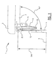
Figures 1 and2 are schematic side views of a legrest according to the invention, in which the legrest is shown to be pivoted through an angle of 90° (figure 1 ) and through an angle of 150° (figure 2 ) with respect to the seat; -
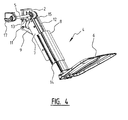
Figures 3 ,4 and5 show various views of the legrest offigures 1 and2 . -
Figures 1 and2 show part of a wheelchair 1, depicting diagrammatically aframework 2, aseat 3 mounted thereon and alegrest 4 connected to theframework 2. The legrest in question is a so-called "central"legrest 4, wherein the legs of a wheelchair user are supported by one legrest situated in a centre longitudinal plane of the wheelchair 1, close to a front edge of theframework 2 and extending downward to within a short distance from the road surface. - The
legrest 4 is connected to theframework 2 so as to be pivotable about apivot pin 5. In accordance with the invention, thelegrest 4 can be pivoted manually in a stepless manner between a downward position, in which afootrest 6 connected to the legrest 4 (seefigures 3 ,4 and5 ) is automatically moved towards thepivot pin 5, and an upward position, in which thefootrest 6 is automatically moved in a direction away from thepivot pin 5. Infigure 1 , thelegrest 4 is pivoted about thepivot pin 5 through an angle of 90° with respect to theseat 3, while infigure 2 thelegrest 4 is pivoted about thepivot pin 5 through an angle of 150° with respect to theseat 3. As a result of automatic movement of thefootrest 6 in the longitudinal direction of thelegrest 4, when thelegrest 4 is manually pivoted, the effective length of thelegrest 4 is infinitely variable between approximately 26.6 cm (figure 1 at a pivoting angle of 90°) and approximately 41.8 cm (figure 2 at a pivoting angle of 1500). By virtue thereof, the feet of a wheelchair user are always optimally supported in any pivoted position of thelegrest 4. - In
figures 3 and4 , thelegrest 4 vanfigures 1 and2 is shown, diagrammatically and in perspective, in an oblique rear view (figure 3 ) and in an oblique front view (figure 4 ), whilefigure 5 is a side view of thelegrest 4 shown infigures 3 en 4. As shown infigures 3 ,4 en 5, thelegrest 4 is composed of afirst portion 7 which is connected to theframework 2 so as to be pivotable about thepivot pin 5, as well as of asecond portion 8 to which thefootrest 6 is mounted. As will be explained at a later stage, the second portion is slidable with respect to the first portion in the longitudinal direction thereof. With reference tofigures 3 ,4 and5 , anarm 9 is provided which is connected to aroller 10 at one end and to theframework 2 at its other end so as to be pivotable about apivot pin 11. Furthermore, there is provided a belt 12(seefigures 1 ,2 and4 ) which is connected at one end to a securingpin 13 on theframework 2, and at its other end to a securingpin 14 on theportion 8 of thelegrest 4. Thebelt 12 runs from thesecuring pin 13 over theroller 10 and over anext roller 15, along theportions legrest 4, to the securingpin 14. - With reference to
figures 1 through 5 , the operation of thelegrest 4 is as follows. By manually pivoting thelegrest 4 about thepivot pin 5 in a stepless manner from a downward position (figure 1 ) to an upward position (figure 2 ), the arm is automatically pivoted about thepivot pin 11 from a position facing away from theframework 2 to a position facing the framework 2 (seefigures 1 and2 ). In this process, theroller 10 is automatically moved upwards in aguideway 16 of the first portion 7(in a direction towards the framework 2). As a result, and seen from theroller 15 to the securingpin 14, the belt is automatically pulled out and thesecond portion 8 is automatically slid downward in the longitudinal direction of thefirst portion 7. Since thefootrest 6 is mounted to thesecond portion 8, thefootrest 6 is also automatically moved downward. The opposite occurs by manually pivoting thelegrest 4 about thepivot pin 5 in a stepless manner from an upward position (figure 2 ) to a downward position (figure 1 ). That is to say, thearm 9 is automatically pivoted about thepivot pin 11 from a position facing theframework 2 to a position facing away from theframework 2. In this process theroller 10 is automatically moved downwards(in a direction away from the framework 2). As a result, (seen from theroller 15 to the securing pin 14) thebelt 12 is automatically pulled out and thesecond portion 8 is automatically slid upward in the longitudinal direction of thefirst portion 7. As a result, thefootrest 6 is also automatically moved upward. - The
legrest 4 can be manually locked in and unlocked from positions between the respective downward and upward positions, to which end use is made of a locking/unlockingdevice 17. - The invention is not limited to the embodiments represented hereinabove, but it also extends to other preferred variants that fall within the scope of the appended claims. For example, it will be clear to the person skilled in the art that the
belt 12 may be connected to thearm 9 or to the roller 10 (instead of to the framework 2) with its other end.
Claims (8)
- A wheelchair comprising at least three wheels, a framework, a seat and a backrest, wherein the wheelchair further comprises a legrest connected to the framework, and wherein the legrest comprises a footrest, characterized in that the legrest is connected to the framework so as to be pivotable about a pivot pin, wherein the legrest can be pivoted manually in a stepless manner between a downward position, in which the footrest is automatically moved towards the pivot pin, and an upward position, in which the footrest is automatically moved in a direction away from the pivot pin.
- A wheelchair according to claim 1, wherein the legrest can be manually locked in and unlocked from positions between the downward position and the upward position.
- A wheelchair according to claim 1 or 2, wherein the legrest comprises a first portion which is connected to the framework so as to be pivotable about the pivot pin, and a second portion comprising the footrest, which second portion is slidably connected to the first portion between a pulled-out position, in which the legrest is pivoted to the upward position, and a pushed-in position, in which the legrest is pivoted to the downward position.
- A wheelchair according to claim 3, wherein the wheelchair comprises a flexible element which is connected at one end to the second portion of the legrest, and which flexible element is adjustable for length between a first position, in which the second portion is pulled-out, and a second position, in which the second portion is pushed-in.
- A wheelchair according to claim 4, wherein the flexible element can be pulled in and pulled out between the first, pulled-out position, and the second, pulled-in position.
- A wheelchair according to claim 5, wherein the flexible element can be pulled in and pulled out over at least one roller.
- A wheelchair according to claim 6, wherein the roller can be moved in the longitudinal direction of the first portion of the legrest in a guideway thereof.
- A wheelchair according to claim 7, wherein the wheelchair comprises an arm which is connected to the roller at one end and which is pivotally connected to the framework at the other end, and wherein the arm is pivotable between a position facing the framework, in which position the flexible element is pulled out and the second portion of the legrest is pulled out, and a position facing away from the framework, in which position the flexible element is pulled in and the second portion of the legrest is pushed in.
Applications Claiming Priority (1)
| Application Number | Priority Date | Filing Date | Title |
|---|---|---|---|
| NL2005469A NL2005469C2 (en) | 2010-10-06 | 2010-10-06 | WHEELCHAIR. |
Publications (1)
| Publication Number | Publication Date |
|---|---|
| EP2438896A1 true EP2438896A1 (en) | 2012-04-11 |
Family
ID=43921375
Family Applications (1)
| Application Number | Title | Priority Date | Filing Date |
|---|---|---|---|
| EP11184146A Withdrawn EP2438896A1 (en) | 2010-10-06 | 2011-10-06 | Wheelchair |
Country Status (2)
| Country | Link |
|---|---|
| EP (1) | EP2438896A1 (en) |
| NL (1) | NL2005469C2 (en) |
Cited By (4)
| Publication number | Priority date | Publication date | Assignee | Title |
|---|---|---|---|---|
| DE102017210397A1 (en) * | 2017-06-21 | 2018-12-27 | Karma Medical Products Co., Ltd. | SEAT DEVICE |
| WO2023126089A1 (en) * | 2021-12-29 | 2023-07-06 | New Live Ingenierie | Telescopic inclinable footrest device for a motorised wheelchair |
| JP2024048173A (en) * | 2022-09-27 | 2024-04-08 | 本田技研工業株式会社 | vehicle |
| EP4474277A1 (en) * | 2023-06-05 | 2024-12-11 | Acro Aircraft Seating Limited | Footrest |
Citations (6)
| Publication number | Priority date | Publication date | Assignee | Title |
|---|---|---|---|---|
| GB1416698A (en) * | 1971-12-02 | 1975-12-03 | Landstingens Inkopscentral | Chair having leg and foot supporting means |
| GB2089204A (en) * | 1980-11-15 | 1982-06-23 | Meyra Krankenfahrzeug | Leg support for a wheelchair |
| DE10109233C1 (en) * | 2001-02-26 | 2002-08-29 | Meyra Wilhelm Meyer Gmbh & Co | wheelchair |
| EP1510193A1 (en) * | 2003-08-29 | 2005-03-02 | Revab B.V. | Wheelchair provided with legrest and calfrest |
| EP1522297A2 (en) * | 2003-10-08 | 2005-04-13 | Pride Mobility Products, Corporation | Extendable and retractable leg rest |
| EP2735292A1 (en) * | 2010-09-30 | 2014-05-28 | Permobil AB | Wheelchair legrest assembly |
-
2010
- 2010-10-06 NL NL2005469A patent/NL2005469C2/en not_active IP Right Cessation
-
2011
- 2011-10-06 EP EP11184146A patent/EP2438896A1/en not_active Withdrawn
Patent Citations (6)
| Publication number | Priority date | Publication date | Assignee | Title |
|---|---|---|---|---|
| GB1416698A (en) * | 1971-12-02 | 1975-12-03 | Landstingens Inkopscentral | Chair having leg and foot supporting means |
| GB2089204A (en) * | 1980-11-15 | 1982-06-23 | Meyra Krankenfahrzeug | Leg support for a wheelchair |
| DE10109233C1 (en) * | 2001-02-26 | 2002-08-29 | Meyra Wilhelm Meyer Gmbh & Co | wheelchair |
| EP1510193A1 (en) * | 2003-08-29 | 2005-03-02 | Revab B.V. | Wheelchair provided with legrest and calfrest |
| EP1522297A2 (en) * | 2003-10-08 | 2005-04-13 | Pride Mobility Products, Corporation | Extendable and retractable leg rest |
| EP2735292A1 (en) * | 2010-09-30 | 2014-05-28 | Permobil AB | Wheelchair legrest assembly |
Cited By (7)
| Publication number | Priority date | Publication date | Assignee | Title |
|---|---|---|---|---|
| DE102017210397A1 (en) * | 2017-06-21 | 2018-12-27 | Karma Medical Products Co., Ltd. | SEAT DEVICE |
| DE102017210397B4 (en) | 2017-06-21 | 2019-03-14 | Karma Medical Products Co., Ltd. | SEAT DEVICE |
| WO2023126089A1 (en) * | 2021-12-29 | 2023-07-06 | New Live Ingenierie | Telescopic inclinable footrest device for a motorised wheelchair |
| WO2023126090A1 (en) * | 2021-12-29 | 2023-07-06 | New Live Ingenierie | Inclinable leg-rest device for wheelchair |
| JP2024048173A (en) * | 2022-09-27 | 2024-04-08 | 本田技研工業株式会社 | vehicle |
| EP4474277A1 (en) * | 2023-06-05 | 2024-12-11 | Acro Aircraft Seating Limited | Footrest |
| GB2631019A (en) * | 2023-06-05 | 2024-12-18 | Acro Aircraft Seating Ltd | Footrest |
Also Published As
| Publication number | Publication date |
|---|---|
| NL2005469C2 (en) | 2012-04-11 |
Similar Documents
| Publication | Publication Date | Title |
|---|---|---|
| US11109682B2 (en) | Folding chair, folding recliner and folding chair frame thereof | |
| CN102481219B (en) | bed and wheelchair | |
| RU2396891C1 (en) | Folding armchair | |
| US7373679B2 (en) | Adjustable mobility assistance device | |
| RU2387435C2 (en) | Wheelchair with vertical seat installation | |
| RU2642036C2 (en) | Articulated bed with adjusted waist and head position | |
| EP1133940B1 (en) | Extensible footrest, particularly for armchairs, sofas and the like | |
| KR101962511B1 (en) | Articulating bed with flexible mattress support | |
| US20060267389A1 (en) | Height-adjustable work chair | |
| JP7411628B2 (en) | Push-up mechanism and chair | |
| US8262163B2 (en) | Upholstered recliner chair with an adjustable backrest padding | |
| US20210068544A1 (en) | Chair Assembly | |
| US8474915B2 (en) | Adjustable ergonomic chair | |
| US20110121625A1 (en) | Lift chair | |
| WO2012033857A1 (en) | Height adjustment mechanism for a massage table | |
| US6839918B1 (en) | Collapsible wheel chair with displaceable seat panels | |
| EP2438896A1 (en) | Wheelchair | |
| US7703854B2 (en) | Lounge chair with adjustable arm rests | |
| US4455050A (en) | Clot preventing chair and attachments | |
| US7222920B1 (en) | Adjustable chair | |
| US4227742A (en) | Multi-position, retractable leg rest for a wheelchair | |
| US7585019B2 (en) | Seat reclining mechanism for power wheelchair | |
| US7644460B2 (en) | Device and method for relieving back pain | |
| CN105960181A (en) | Extendable seating and/or reclining furniture items, especially chairs, armchairs, sofas or chaise longues | |
| CN108125434A (en) | A kind of chair |
Legal Events
| Date | Code | Title | Description |
|---|---|---|---|
| AK | Designated contracting states |
Kind code of ref document: A1 Designated state(s): AL AT BE BG CH CY CZ DE DK EE ES FI FR GB GR HR HU IE IS IT LI LT LU LV MC MK MT NL NO PL PT RO RS SE SI SK SM TR |
|
| AX | Request for extension of the european patent |
Extension state: BA ME |
|
| PUAI | Public reference made under article 153(3) epc to a published international application that has entered the european phase |
Free format text: ORIGINAL CODE: 0009012 |
|
| 17P | Request for examination filed |
Effective date: 20121011 |
|
| 17Q | First examination report despatched |
Effective date: 20150616 |
|
| STAA | Information on the status of an ep patent application or granted ep patent |
Free format text: STATUS: THE APPLICATION IS DEEMED TO BE WITHDRAWN |
|
| 18D | Application deemed to be withdrawn |
Effective date: 20151027 |