EP2438973A1 - Séparateur destiné à la séparation de matières solides, notamment à partir de liquides hautement visqueux - Google Patents
Séparateur destiné à la séparation de matières solides, notamment à partir de liquides hautement visqueux Download PDFInfo
- Publication number
- EP2438973A1 EP2438973A1 EP11008091A EP11008091A EP2438973A1 EP 2438973 A1 EP2438973 A1 EP 2438973A1 EP 11008091 A EP11008091 A EP 11008091A EP 11008091 A EP11008091 A EP 11008091A EP 2438973 A1 EP2438973 A1 EP 2438973A1
- Authority
- EP
- European Patent Office
- Prior art keywords
- filter
- core element
- sliding
- sliding elements
- product
- Prior art date
- Legal status (The legal status is an assumption and is not a legal conclusion. Google has not performed a legal analysis and makes no representation as to the accuracy of the status listed.)
- Withdrawn
Links
- 239000007788 liquid Substances 0.000 title claims description 22
- 239000007787 solid Substances 0.000 title claims description 19
- 238000007790 scraping Methods 0.000 claims description 5
- 239000002184 metal Substances 0.000 claims description 2
- 238000007599 discharging Methods 0.000 claims 2
- 230000005855 radiation Effects 0.000 claims 1
- 239000000047 product Substances 0.000 description 54
- 238000000926 separation method Methods 0.000 description 33
- 239000002245 particle Substances 0.000 description 18
- 239000012065 filter cake Substances 0.000 description 9
- 239000011295 pitch Substances 0.000 description 7
- 238000004140 cleaning Methods 0.000 description 5
- 230000008719 thickening Effects 0.000 description 5
- 230000033001 locomotion Effects 0.000 description 4
- 238000011161 development Methods 0.000 description 3
- 230000018109 developmental process Effects 0.000 description 3
- 238000009434 installation Methods 0.000 description 3
- XLYOFNOQVPJJNP-UHFFFAOYSA-N water Substances O XLYOFNOQVPJJNP-UHFFFAOYSA-N 0.000 description 3
- 230000004323 axial length Effects 0.000 description 2
- 238000011109 contamination Methods 0.000 description 2
- 230000007423 decrease Effects 0.000 description 2
- 230000001419 dependent effect Effects 0.000 description 2
- 239000000463 material Substances 0.000 description 2
- 239000000203 mixture Substances 0.000 description 2
- 230000000750 progressive effect Effects 0.000 description 2
- 239000010802 sludge Substances 0.000 description 2
- 239000002351 wastewater Substances 0.000 description 2
- 241001674044 Blattodea Species 0.000 description 1
- 238000005452 bending Methods 0.000 description 1
- 230000001680 brushing effect Effects 0.000 description 1
- 238000006243 chemical reaction Methods 0.000 description 1
- 239000007795 chemical reaction product Substances 0.000 description 1
- 230000001427 coherent effect Effects 0.000 description 1
- 238000010276 construction Methods 0.000 description 1
- 230000003247 decreasing effect Effects 0.000 description 1
- 230000006866 deterioration Effects 0.000 description 1
- 238000005516 engineering process Methods 0.000 description 1
- 239000000706 filtrate Substances 0.000 description 1
- 238000001914 filtration Methods 0.000 description 1
- 230000010006 flight Effects 0.000 description 1
- 230000005484 gravity Effects 0.000 description 1
- 238000004519 manufacturing process Methods 0.000 description 1
- 238000005192 partition Methods 0.000 description 1
- 230000036316 preload Effects 0.000 description 1
- 230000002028 premature Effects 0.000 description 1
- 235000014059 processed cheese Nutrition 0.000 description 1
- 239000012264 purified product Substances 0.000 description 1
- 239000010865 sewage Substances 0.000 description 1
- 239000007858 starting material Substances 0.000 description 1
Images


Classifications
-
- B—PERFORMING OPERATIONS; TRANSPORTING
- B01—PHYSICAL OR CHEMICAL PROCESSES OR APPARATUS IN GENERAL
- B01D—SEPARATION
- B01D29/00—Filters with filtering elements stationary during filtration, e.g. pressure or suction filters, not covered by groups B01D24/00 - B01D27/00; Filtering elements therefor
- B01D29/11—Filters with filtering elements stationary during filtration, e.g. pressure or suction filters, not covered by groups B01D24/00 - B01D27/00; Filtering elements therefor with bag, cage, hose, tube, sleeve or like filtering elements
- B01D29/117—Filters with filtering elements stationary during filtration, e.g. pressure or suction filters, not covered by groups B01D24/00 - B01D27/00; Filtering elements therefor with bag, cage, hose, tube, sleeve or like filtering elements arranged for outward flow filtration
- B01D29/118—Filters with filtering elements stationary during filtration, e.g. pressure or suction filters, not covered by groups B01D24/00 - B01D27/00; Filtering elements therefor with bag, cage, hose, tube, sleeve or like filtering elements arranged for outward flow filtration open-ended
-
- B—PERFORMING OPERATIONS; TRANSPORTING
- B01—PHYSICAL OR CHEMICAL PROCESSES OR APPARATUS IN GENERAL
- B01D—SEPARATION
- B01D29/00—Filters with filtering elements stationary during filtration, e.g. pressure or suction filters, not covered by groups B01D24/00 - B01D27/00; Filtering elements therefor
- B01D29/62—Regenerating the filter material in the filter
- B01D29/64—Regenerating the filter material in the filter by scrapers, brushes, nozzles, or the like, acting on the cake side of the filtering element
- B01D29/6469—Regenerating the filter material in the filter by scrapers, brushes, nozzles, or the like, acting on the cake side of the filtering element scrapers
- B01D29/6476—Regenerating the filter material in the filter by scrapers, brushes, nozzles, or the like, acting on the cake side of the filtering element scrapers with a rotary movement with respect to the filtering element
-
- B—PERFORMING OPERATIONS; TRANSPORTING
- B30—PRESSES
- B30B—PRESSES IN GENERAL
- B30B9/00—Presses specially adapted for particular purposes
- B30B9/02—Presses specially adapted for particular purposes for squeezing-out liquid from liquid-containing material, e.g. juice from fruits, oil from oil-containing material
- B30B9/12—Presses specially adapted for particular purposes for squeezing-out liquid from liquid-containing material, e.g. juice from fruits, oil from oil-containing material using pressing worms or screws co-operating with a permeable casing
- B30B9/121—Screw constructions
Definitions
- the invention relates to a separator for the separation of solids from in particular highly viscous liquids, according to the preamble of claim 1 or 3.
- the patent DE 34 20 18 shows a continuously operating filter press with a plurality of cylindrical filter elements, in the interior of each a rotatable Schrautaenplanetaryl or spiral is arranged.
- the product to be filtered is thus guided by means of the spiral from top to bottom axially along the filter surface and separated part of the solids contained therein.
- the separation product is precipitated as a filter cake.
- Disadvantage is the low separation efficiency, since the spirals are continuous and uninterrupted and therefore too much good product is eliminated together with the separation product from the filter press.
- the filter cake on the filter surface is very advantageously divided into several separate sector-shaped partial surfaces, which can be removed very easily, without special blower with the aid of the scraper of the filter surface.
- disadvantage is that only a single scraper on each side of the filter surface is provided, which of course brings a significant loss of separation efficiency with it, since the filter cake builds up constantly where just the scraper is not working.
- the scraped off by the scraper filter cake falls uncontrollably back into the liquid to be purified, so that it is only concentrated in total, but not with a gradual or constant increase in the solids concentration towards the outlet, resulting in a further reduction of the separation efficiency.
- the DE 39 27 707 A1 discloses a filter centrifuge comprising a cylindrical drum rotatably mounted within a centrifugal housing, whose jacket is perforated like a sieve and covered with a filter.
- An axially parallel paring knife which can be swiveled into a working position just in front of the filter surface and can be advanced over the entire height of the drum, is followed by a mechanical scraper, which is pressed resiliently against the surface of the filter.
- two rows of scraper blades may be oblique to the direction of rotation of the drum.
- the filter cake separated by the two rows of scraper flakes falls uncontrollably back into the liquid to be purified, so that it is only concentrated overall, but not with a gradual or constant increase in the solids concentration towards the outlet , which leads to a reduction in the separation efficiency.
- Another embodiment provides a kind of disc harrow whose discs are inclined to the direction of the drum, with the aforementioned disadvantages.
- Yet another embodiment provides a resilient spiral as a scraper, but has the disadvantage that the spiral is continuous and uninterrupted and therefore too much good product is eliminated together with the separation product from the filter centrifuge, so that the separation efficiency is reduced.
- the device of DE 198 52 119 C1 It can be used in sewage treatment plants and is used to separate waste water from wastewater laden with solids, especially on ships.
- the solution consists in that a separation device has a hollow shaft, at the ends in the direction of the lower plenum a, the hollow shaft inside appropriately trained, rotatable screw connects, which is guided over the screw flights in a support bearing the partition, and the hollow shaft circumferentially brushing which are enclosed by a Feinsiebzylinder, wherein either the hollow shaft rotatable and the Feinsiebzylinder are fixed and vice versa, and the screw conveyor is connected to either the rotatable hollow shaft or the rotary fine screen cylinder, and the upper plenum via openings, the interior of the hollow shaft Disadvantage is the low separation efficiency, since the plurality of tightly packed spiral brushes act almost as a continuous and continuous spiral and therefore from de m dirty water is filtered out too little clean water before the dirty water with a slightly higher concentration of dirt is excreted from the device again
- WO 2010/070112 A1 in processed cheese making generally discloses the basic principle of a ring filter having a core member rotating therein and having scrapers on its outer periphery which move along the inner circumference of the filter surface.
- the disadvantage is that the scrapers scraping along the inner circumference of the filter surface, ie the so-called rake angle between the scraper and the vertical normal to the filter surface is negative, wherein the Schabewinkel between scraper and filter surface is greater than or equal to 90 °. This scraping forces the smaller solids to be separated into the holes of the filter, resulting in premature filter interlock and decreased pump power.
- the larger solids to be separated are not divided into smaller parts and discharged downwards, but remain for too long on the surface of the filter in the area of the scraper, so that this too leads to an early filter interlock and decrease the pump power, but also to an increased driving power of the rotary motor for the core element. Overall, thus the separation efficiency is reduced.
- this increase in the separation efficiency should take place in a shorter separation time, and the separation device should not be more costly than in the prior art.
- the present invention differs on the one hand from the DE 10 2008 063 972 A1 respectively.
- WO 2010/070112 A1 in that in the operating state, the sliding elements with the tangential of the filter inner wall form a cutting angle between 0 ° and 90 °, and with the vertical normal to the filter inner wall a positive Abtragewinkel.
- the scrapers form at the nearest DE 10 2008 063 972 A1 or WO 20101070112 A1 with the tangential of the filter inner wall a Schabewinkel greater than 90 °, and with the vertical normal to the filter inner wall a negative Abtragewinkel.
- the present invention further differs from the DE 10 2008 063 972 A1 respectively.
- WO 2010/070112 A1 in that a special promotion of the highly viscous liquid to be filtered by the special arrangement of the sliding elements takes place, because they are arranged approximately helically, so as to achieve a forced flow of the highly viscous liquid to be filtered in the direction of the discharge opening for the separation product.
- the sliding elements are thus arranged one behind the other along the longitudinal axis of the shell of the core element on at least one imaginary helical line and have between them a distance in the axial and / or circumferential direction of the core element through which liquid to be purified can flow.
- adjacent sliding elements overlap in the circumferential direction of the core element.
- the advantage here is that thus a small spiral flow of the liquid to be cleaned is generated in the direction of the outlet and the dirt removed by the filter inner wall by the sliding dirt particles are transported quite quickly from sliding element to sliding element in the direction of the outlet and only small amounts thereof back into the liquid to be cleaned and back to the filter.
- the liquid to be purified flows mainly in the direction of the filter and only slightly helical towards the outlet, so that always first on the filter, a separation of the solids from the liquid before these solids with the low spiral flow and depending Depending on the installation position, it may also be conveyed in the direction of the outlet on the same and / or the adjacent spiral due to gravity, in particular from the sliding element to the next axially spaced sliding element.
- the essence of the invention lies in the special Abreln Trentstechnik in which a multi-start helical coil is arranged on a cylindrical or conical core of a cleaning device and are arranged in the region of this helix perpendicular thereto and spaced apart sliding plastic, which are elastically resilient in the bending direction Put on the inner wall of the filter and stroke in the thrust direction on the filter inner wall, so as to allow a separation of the good product from the bad product. It is done so a cleaning of the filter inner wall by cutting the particles in / on the holes and further transport towards the drain. Separation takes place during the transport to the outflow, through which good products pass through the holes in the direction of the secondary side again and again, thus thickening the product on the primary side.
- the particles that do not go completely through the holes are cut off by the sliding elements in the form of plastic segments.
- the sliding elements lie against the filter inner wall via a defined preload, which is generated by the arrangement of Gleitelementhalterung on the core element, by the residual stress of the Gleitelernentmatehals.
- WO 20101070112 A1 do that over an ellipse that jams like a wedge between the scraper core and the filter inner wall. Disadvantage: Very high load from the filter element due to the forces generated by the wedge.
- the sliding elements with clearance angle about 20 °, wedge angle about 90 ° of the present invention cut after a certain period of operation, since they re-sharpen themselves and the negative rake angle changes with the resharpening, so it becomes positive.
- the arrangement of the sliding element according to the invention is seen in the 3D image in 2 dimensions different.
- the sliding element according to the invention is angular.
- the spiral scraper is an approximately 180 ° Ronde / semicircle with retaining tabs and slots that the plastic rests better on the filter wall.
- WO 2010/070112 A1 does not describe the contour of the sliding elements referred to therein as "slats", these are telescoping ellipses.
- the present invention does not work with a relatively small volume annulus but requires a relatively large volume annulus.
- a rotational direction is set and thereby the positions and orientations of the plastic segments result, which means that a core element is designed for left or right-handed rotation. During production, the core element always turns in one direction only.
- the direction of rotation of the present invention is not relevant because it can also be installed mirror-inverted (upside down).
- the present invention thickens the product and separates the particles larger than the hole size of the filter.
- WO 2010/070112 A1 has no thickening or separating.
- WO 2010/070112 A1 are thicker. 112 and 3mm possible depending on the product
- the sliding elements according to the invention are firmly clamped in the core element or clipped there in a quick release system.
- WO 2010/070112 A1 lie loose in an elliptical slot, with no attachment and no clipping or the like, and the sliding elements fall out of the filter interior during installation and removal very easy.
- the present invention does not use flow rates.
- the core element carrying the sliding elements preferably has an outer diameter of 80 mm and an axial length of about 550 mm, but may also have other dimensions.
- the plurality of Gleitelementhalterieux and mounted thereon sliding elements are also distributed to the core element in the form of a 2-threaded thread with a pitch of 50 mm.
- the position of the Gleitelementhalterieux to the axis of the core member is preferably about 45 °.
- Each sliding element is offset by 10 mm in the direction of the longitudinal axis of the core element to the adjacent sliding element.
- the Gleitelementhalter Is applied (in particular welded) on the core element, that the Gleitelementhalter to the tangent of the outer shell of the core element occupies about 10 °.
- a 2-threaded thread is a 2-threaded thread.
- the Gleitelementhalterept are rotated 45 ° to the central axis and are 40mm long.
- a 1,2,3,4 ?? common thread would work the same, so that all single and multiple threads are claimed.
- a 2-threaded thread since in this arrangement about 50 pieces of sliding elements in a corridor and thus at two courses 100 pieces of sliding elements can be distributed.
- the offset is necessary to pass the cut particles that accumulate on the sliding elements from one slider to another.
- the sliding elements are thus arranged overlapping on the slope. If the offset is 10 mm and e.g. 8 sliding elements in one turn, the pitch would be 80 mm. If the offset is 6 mm and 8 sliding elements in one turn, the pitch would be 48 mm. A distortion of 48 mm on the preferred 50 mm pitch results from the conversion of diameter and scale. It does not matter which slope is actually used. The offset is thus the pitch per slider.
- the filter element may be cylindrical or conical.
- the hole size of the filter element is between 30 and 400 microns, the hole pattern and the shape of the apertures does not matter.
- the sliding elements have an elastically resilient bias in the installed state in the filter.
- the sliding elements are screwed to the core element or clamped or clipped there.
- the separator according to the invention can be operated in any position, standing with inlet above and outlet below or vice versa or even lying or even obliquely with its longitudinal axis at an angle to the horizontal.
- the product to be processed must be pumpable, whereby the contact pressure of the pump is determined by the type, size and amount of contamination as well as the viscosity of the product to be processed.
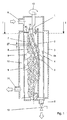
- FIG. 1 the separator according to the invention is shown in longitudinal section for a first embodiment, which has a hollow cylindrical stirnitig open filter element 4 with jacket perforations in the micron range in the interior 10 of a hollow cylindrical front side, in the interior 7 in turn a hollow cylindrical core element 2 is added, which on a drive shaft 1 by means of an electric motor, not shown in the clockwise direction 13 is driven.
- Gleitelementhaltem 8 On the outer jacket of the rotatable core element 2, a plurality of Gleitelementhaltem 8 is now housed in a special arrangement, which will be described in more detail below, in each case a sliding element 9, 9a, 9b made of plastic is added to these Gleitelementhaltern 8.
- an inlet 6 for the product to be cleaned is provided in the housing 3, which then flows on the primary side into the interior 7 of the core element 2.
- the product to be cleaned is filtered through the plurality of sliding elements 9 on the one hand through the plurality of openings in the micron range in the filter element 4 as a purified product and flows out of the output 11 for good product.
- the unwanted solids in the product to be cleaned from the inner wall 4 a of the filter element 4 are scraped and crushed, as well as spirally down towards output 5 and drain valve 12 promoted, due to the spiral arrangement of the sliding elements 9 on the shell of the core element. 2
- adjacent sliding elements 9 have a distance 27 from each other, wherein the sliding elements 9 of an imaginary spiral 14, 15 but can overlap circumferentially.
- the concentration of unwanted solids in the interior 10 of the housing 3 decreases from top to bottom, i. from the inlet 6 to the outlet 5 strongly progressive, wherein at the bottom of the housing 3, the highest solids concentration prevails.
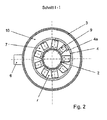
- FIG. 2 is a radial cross section through the separator after FIG. 1 shown along the arrows 1-1.
- FIG. 3 It schematically shows only the core element 2 with the sliding element holders 8 and the sliding elements 9 fastened thereon. It can be seen that two imaginary spirals 14, 15 axially displaced from one another by 25 mm are present on the shell on which the sliding element holders 8 with sliding elements 9 are located. This results in a pitch of 50 mm for each imaginary spiral 14, 15 and an axial offset of about 10 mm for adjacent Gleitelementhalter 8 with sliding elements 9 on one of the spirals 14, 15th
- Gleitelementhalter 8 Per revolution of the imaginary spirals 14, 15 8 piece Gleitelementhalter 8 are each arranged with a sliding element 9 evenly distributed over the circumference, so that there is a circumferential angular distance of 45 ° between the Gleitelementhaltem 8 and sliding elements 9.
- the Gleitelementhalter 8 and sliding elements 9 on the first imaginary spiral 14 are also offset to the Gleitelementhaltem 8 and sliding elements 9 of the second imaginary spiral 15 by a circumferential angular distance of 22.5 °.
- FIG. 4 shows the development of the cylinder of the core element 2 of FIG. 3 from which, in turn, the pitches of 50 mm for the two imaginary spirals 14, 15 emerge, but also that the width axis 16 of each Gleitelementhalters 8 and the longitudinal axes 17 of each slider 9 are rotated by 45 ° to the longitudinal axis of the core element 2.
- the contact surface 18 of the sliding elements 9, which run on the inner circumferential surface of the filter 4 also chamfered by 45 ° to the longitudinal axes 17 of the sliding element 9, so that the entire end face 26 can contact the filter 4.
- FIG. 5 schematically represents the angular deflection of the Gleitelementhalters 8 and the sliding member 9 from the tangential 19 of the core member 2 of 10 ° in the expanded state of the filter element 4.
- Clearance angle 22 is the angle between the tangential 20 of the filter element 4 and the radially outer longitudinal surface 24 of the slider 9.
- the wedge angle 29 is the angle of the wedge, the forms the cutting or scraping edge 18 of the sliding element 9, which lies here between the radially outer longitudinal surface 24 of the sliding element 9 and the front end surface 26 of the sliding element 9.
- the rake angle 23 of the slider 9 is defined as 90 ° (i.e., the angle of the normal 21 to the tangent 20) minus the angle of intersection 28, which is positive at “cutting” and negative at "cockroaching".
- a sliding member 9b which has a wedge angle 29 of 90 °, so that the rake angle or Abtragewinkel 23 of the sliding element 9 is negative and is at minus 45 °, if the clearance angle 22 is for example 45 °, so that the intersection angle 28th at 135 °.
- the clearance angle 22 is in FIG. 7 about 25 °, the wedge angle 29 about 30 °, therefore, the cutting angle 28 is here about 55 °, as is the positive chip / Abtragewinkel 23 at + 35 °. So here is a cutting sliding element 9a.
- FIGS. 6 and 7 with respect to the angular relationships of the sliding elements 8 apply to both embodiments according to the Figures 1-5 and FIGS. 8 and 9, which will be described below.
- FIGS. 8 and 9 the separator according to the invention is the Figures 1-7 shown in an alternative embodiment, wherein the angular arrangements of the sliding element 9 of the FIGS. 6 and 7 but identical in both embodiments.
- the sliding element holders 8 are made of two mutually parallel, a small mutual distance of e.g. 2 cm slipper holder spirals 34 e.g. formed of metal wire, which are applied to V-shaped brackets 30, which in turn are welded onto the outer jacket of the core element 2.
- the Gleitelementhalter spirals 34 are continuously interrupted or just interrupted by short sections.
- the slide element holders 8 include slide element holder hooks 31 spaced apart from e.g. 2 cm are welded to the upper Gleitelementhalter-spiral 34 on the outer surface of the core member 2 and in which the sliding elements 9 can be hung or clipped with eyelets 32.
- the Gleitelementhalter spirals 34 are welded to the free ends of the legs of the V-shaped bracket 30, which in turn are welded to the connection point of the two legs on the outer surface of the core element 2.
- the sliding elements 9 are further arranged along at least one imaginary helical line 14 lying one behind the other on the shell of the core element 2 and have between them a distance 27 in the axial and / or circumferential direction of the core element 2, through which liquid to be purified can flow.
- the sliding elements 9 are formed on one or more sliding element spiral bands 33 in one piece or cohesively.
- a 360 ° sliding element spiral band 33 is provided per approx. 20 cm axial length of the core element 2.
- the sliding element spiral bands 33 of the sliding elements 9 are then inserted between the two sliding element holder spirals 34, the upper receiving lugs 32 of the sliding element holder spirals 34 are positively hooked into the sliding element holder hooks 31, and the sliding element spiral tapes 33 are frictionally pressed down, so that the entire sliding element spiral bands 33 are elastically clamped and fixed in position between the two sliding element holder spirals 34.
- the hooks 31 on the core element 2 and eyelets 32 in the holder 8 can of course also be interchanged with each other, so that the hooks 31 can be provided on the holder 8 and the eyelets 32 on the core element 2.
- Advantages of this second embodiment are that only a few slider spiral bands 33 are present, which are simple and quick to assemble and disassemble by simply clamping and clipping into the Gleitelementhalter 8.
- the abutment surfaces between the slider spiral tapes 33 and the slider holder spirals 34 are reduced, and further, the slider spiral tapes 33 are elastically resilient on the slider holder spirals 34, so that cleaning can be performed less frequently, easily, and quickly.
Landscapes
- Chemical & Material Sciences (AREA)
- Chemical Kinetics & Catalysis (AREA)
- Engineering & Computer Science (AREA)
- Mechanical Engineering (AREA)
- Filtration Of Liquid (AREA)
Applications Claiming Priority (1)
| Application Number | Priority Date | Filing Date | Title |
|---|---|---|---|
| DE102010048028A DE102010048028A1 (de) | 2010-10-09 | 2010-10-09 | Separator zur Abtrennung von Feststoffen aus insbesondere hochviskosen Flüssigkeiten |
Publications (1)
| Publication Number | Publication Date |
|---|---|
| EP2438973A1 true EP2438973A1 (fr) | 2012-04-11 |
Family
ID=45023477
Family Applications (1)
| Application Number | Title | Priority Date | Filing Date |
|---|---|---|---|
| EP11008091A Withdrawn EP2438973A1 (fr) | 2010-10-09 | 2011-10-06 | Séparateur destiné à la séparation de matières solides, notamment à partir de liquides hautement visqueux |
Country Status (2)
| Country | Link |
|---|---|
| EP (1) | EP2438973A1 (fr) |
| DE (2) | DE102010048028A1 (fr) |
Cited By (2)
| Publication number | Priority date | Publication date | Assignee | Title |
|---|---|---|---|---|
| CN105829057A (zh) * | 2013-10-04 | 2016-08-03 | 奥地利埃瑞玛再生工程机械设备有限公司 | 过滤器装置 |
| WO2021019494A1 (fr) * | 2019-08-01 | 2021-02-04 | Zvi Livni | Appareil de filtration autonettoyant pour échangeurs de chaleur à plaques |
Families Citing this family (2)
| Publication number | Priority date | Publication date | Assignee | Title |
|---|---|---|---|---|
| AT514439B1 (de) * | 2013-10-04 | 2015-01-15 | Erema | Filtervorrichtung |
| CN107670362A (zh) * | 2017-10-20 | 2018-02-09 | 新乡市华航航空液压设备有限公司 | 一种高纳污容量结构的滤芯 |
Citations (11)
| Publication number | Priority date | Publication date | Assignee | Title |
|---|---|---|---|---|
| DE342018C (de) | 1918-08-02 | 1921-10-26 | Plauson S Forschungsinstitut G | Kontinuierlich arbeitende Filterpresse |
| US2553567A (en) * | 1945-12-05 | 1951-05-22 | Joseph F Fette | Filter |
| US3762563A (en) * | 1971-02-23 | 1973-10-02 | P Petersen | Cylindrical rotary strainer |
| EP0312354A2 (fr) * | 1987-10-16 | 1989-04-19 | Cellier Corporation | Filtre de boue |
| DE3809372A1 (de) | 1988-03-19 | 1989-09-28 | Kloeckner Humboldt Deutz Ag | Filter |
| DE3927707A1 (de) | 1988-08-25 | 1990-03-01 | Ciba Geigy Ag | Filterzentrifuge |
| JPH10272309A (ja) * | 1997-03-31 | 1998-10-13 | Muramoto Kensetsu Kk | 廃水処理装置およびその濾過装置 |
| DE19852119C1 (de) | 1998-11-12 | 2000-07-27 | Martin Systems Ag | Vorrichtung zum Abscheiden von Schmutzwasser |
| WO2005098341A1 (fr) * | 2004-04-05 | 2005-10-20 | Heco Filtration A/S | Procede et unite de filtrage pour realiser un filtrage dans des echangeurs thermiques |
| AT413497B (de) * | 2004-10-25 | 2006-03-15 | Erema | Vorrichtung zum kontinuierlichen filtern von fliessfähigen massen, die feststoffteilchen enthalten |
| WO2010070112A1 (fr) | 2008-12-19 | 2010-06-24 | Hochland Ag | Filtre destiné à être utilisé dans le traitement de produits alimentaires |
-
2010
- 2010-10-09 DE DE102010048028A patent/DE102010048028A1/de not_active Withdrawn
-
2011
- 2011-09-22 DE DE202011105998U patent/DE202011105998U1/de not_active Expired - Lifetime
- 2011-10-06 EP EP11008091A patent/EP2438973A1/fr not_active Withdrawn
Patent Citations (12)
| Publication number | Priority date | Publication date | Assignee | Title |
|---|---|---|---|---|
| DE342018C (de) | 1918-08-02 | 1921-10-26 | Plauson S Forschungsinstitut G | Kontinuierlich arbeitende Filterpresse |
| US2553567A (en) * | 1945-12-05 | 1951-05-22 | Joseph F Fette | Filter |
| US3762563A (en) * | 1971-02-23 | 1973-10-02 | P Petersen | Cylindrical rotary strainer |
| EP0312354A2 (fr) * | 1987-10-16 | 1989-04-19 | Cellier Corporation | Filtre de boue |
| DE3809372A1 (de) | 1988-03-19 | 1989-09-28 | Kloeckner Humboldt Deutz Ag | Filter |
| DE3927707A1 (de) | 1988-08-25 | 1990-03-01 | Ciba Geigy Ag | Filterzentrifuge |
| JPH10272309A (ja) * | 1997-03-31 | 1998-10-13 | Muramoto Kensetsu Kk | 廃水処理装置およびその濾過装置 |
| DE19852119C1 (de) | 1998-11-12 | 2000-07-27 | Martin Systems Ag | Vorrichtung zum Abscheiden von Schmutzwasser |
| WO2005098341A1 (fr) * | 2004-04-05 | 2005-10-20 | Heco Filtration A/S | Procede et unite de filtrage pour realiser un filtrage dans des echangeurs thermiques |
| AT413497B (de) * | 2004-10-25 | 2006-03-15 | Erema | Vorrichtung zum kontinuierlichen filtern von fliessfähigen massen, die feststoffteilchen enthalten |
| WO2010070112A1 (fr) | 2008-12-19 | 2010-06-24 | Hochland Ag | Filtre destiné à être utilisé dans le traitement de produits alimentaires |
| DE102008063972A1 (de) | 2008-12-19 | 2010-07-01 | Hochland Ag | Filter zum Einsatz in der Schmelzkäseherstellung |
Cited By (3)
| Publication number | Priority date | Publication date | Assignee | Title |
|---|---|---|---|---|
| CN105829057A (zh) * | 2013-10-04 | 2016-08-03 | 奥地利埃瑞玛再生工程机械设备有限公司 | 过滤器装置 |
| WO2021019494A1 (fr) * | 2019-08-01 | 2021-02-04 | Zvi Livni | Appareil de filtration autonettoyant pour échangeurs de chaleur à plaques |
| US20220268537A1 (en) * | 2019-08-01 | 2022-08-25 | Zvi Livni | Self cleaning filtering apparatus for plate heat exchangers |
Also Published As
| Publication number | Publication date |
|---|---|
| DE202011105998U1 (de) | 2011-11-03 |
| DE102010048028A1 (de) | 2012-04-12 |
Similar Documents
| Publication | Publication Date | Title |
|---|---|---|
| DE69304281T2 (de) | Gerät zum trennen von feststoffen und flüssigkeiten | |
| DE69123601T2 (de) | Spindelpresse | |
| EP2155353B1 (fr) | Séparateur à vis à pression | |
| EP2326493B1 (fr) | Filtre-presse à vis sans fin | |
| EP2375888B1 (fr) | Filtre destiné à être utilisé dans le traitement de produits alimentaires | |
| EP0040425A2 (fr) | Dispositif pour évacuer des matériaux flottants et débris d'un égout, notamment d'une installation d'épuration | |
| EP0908569A1 (fr) | Dispositif de tamisage pour eaux usées dans une canalisation | |
| AT413497B (de) | Vorrichtung zum kontinuierlichen filtern von fliessfähigen massen, die feststoffteilchen enthalten | |
| EP2438973A1 (fr) | Séparateur destiné à la séparation de matières solides, notamment à partir de liquides hautement visqueux | |
| DE3122131A1 (de) | Vorrichtung zur entnahme und entwaesserung von feststoffen aus fluessigkeiten, insbesondere aus gerinnen von klaeranlagen | |
| EP2433692A1 (fr) | Dispositif pour le tamisage et l'enlèvement de matière à partir d'un liquide coulant dans un canal | |
| WO2007128467A1 (fr) | Réacteur à empilement de plaques filtrantes | |
| DE19718502A1 (de) | Einrichtung zur Schlammentwässerung | |
| EP3579976B1 (fr) | Dispositif de broyage | |
| AT395325B (de) | Vorrichtung zum auftrennen einer zellulosefaserbrei-suspension | |
| EP3150558B1 (fr) | Procédé du nettoyage des eaux de lavage usées provenant d'une installation de lavage des véhicules et installation de lavage des véhicules | |
| EP1305098B1 (fr) | Dispositif d'extraction permettant l'extraction de liquide a partir de corps solides, et son utilisation | |
| EP0736370A2 (fr) | Appareil de déshydratation de matériaux | |
| EP0465840B1 (fr) | Dispositif de filtration, notamment pour la séparation de grosses particules d'une suspension de lubrifiant et leur utilisation | |
| EP0623712A2 (fr) | Dispositif pour extraire des matériaux séparables d'un liquide | |
| DE4006970A1 (de) | Vorrichtung zur reinigung von abwasser | |
| DE9205674U1 (de) | Gerät für die mechanische Reinigung von Flüssigkeiten in Gerinnen oder in Behältern | |
| EP0972553B1 (fr) | Dispositif de separation pour l emploi dans la fabrication des plaquettes de circuits imprimés | |
| DE9100126U1 (de) | Vorrichtung zum Entfernen von Rechen- und/oder Siebgut aus einem Gerinne strömender Flüssigkeit | |
| DE102009007131A1 (de) | Filtervorrichtung |
Legal Events
| Date | Code | Title | Description |
|---|---|---|---|
| AK | Designated contracting states |
Kind code of ref document: A1 Designated state(s): AL AT BE BG CH CY CZ DE DK EE ES FI FR GB GR HR HU IE IS IT LI LT LU LV MC MK MT NL NO PL PT RO RS SE SI SK SM TR |
|
| AX | Request for extension of the european patent |
Extension state: BA ME |
|
| PUAI | Public reference made under article 153(3) epc to a published international application that has entered the european phase |
Free format text: ORIGINAL CODE: 0009012 |
|
| 17P | Request for examination filed |
Effective date: 20120605 |
|
| 17Q | First examination report despatched |
Effective date: 20130408 |
|
| TPAC | Observations filed by third parties |
Free format text: ORIGINAL CODE: EPIDOSNTIPA |
|
| TPAB | Information related to observations by third parties deleted |
Free format text: ORIGINAL CODE: EPIDOSDTIPA |
|
| STAA | Information on the status of an ep patent application or granted ep patent |
Free format text: STATUS: THE APPLICATION HAS BEEN WITHDRAWN |
|
| 18W | Application withdrawn |
Effective date: 20130904 |