EP2444936A2 - Disparitätseinschätzungssystem, Vorrichtung und Verfahren zur Einschätzung der durchgehenden Disparität eines Videos mit mehreren Ansichten - Google Patents
Disparitätseinschätzungssystem, Vorrichtung und Verfahren zur Einschätzung der durchgehenden Disparität eines Videos mit mehreren Ansichten Download PDFInfo
- Publication number
- EP2444936A2 EP2444936A2 EP11185725A EP11185725A EP2444936A2 EP 2444936 A2 EP2444936 A2 EP 2444936A2 EP 11185725 A EP11185725 A EP 11185725A EP 11185725 A EP11185725 A EP 11185725A EP 2444936 A2 EP2444936 A2 EP 2444936A2
- Authority
- EP
- European Patent Office
- Prior art keywords
- disparity
- respect
- energy function
- energy
- term
- Prior art date
- Legal status (The legal status is an assumption and is not a legal conclusion. Google has not performed a legal analysis and makes no representation as to the accuracy of the status listed.)
- Withdrawn
Links
Images


Classifications
-
- G—PHYSICS
- G06—COMPUTING OR CALCULATING; COUNTING
- G06T—IMAGE DATA PROCESSING OR GENERATION, IN GENERAL
- G06T7/00—Image analysis
- G06T7/50—Depth or shape recovery
- G06T7/55—Depth or shape recovery from multiple images
- G06T7/593—Depth or shape recovery from multiple images from stereo images
-
- H—ELECTRICITY
- H04—ELECTRIC COMMUNICATION TECHNIQUE
- H04N—PICTORIAL COMMUNICATION, e.g. TELEVISION
- H04N13/00—Stereoscopic video systems; Multi-view video systems; Details thereof
- H04N13/20—Image signal generators
- H04N13/282—Image signal generators for generating image signals corresponding to three or more geometrical viewpoints, e.g. multi-view systems
-
- G—PHYSICS
- G06—COMPUTING OR CALCULATING; COUNTING
- G06T—IMAGE DATA PROCESSING OR GENERATION, IN GENERAL
- G06T2207/00—Indexing scheme for image analysis or image enhancement
- G06T2207/10—Image acquisition modality
- G06T2207/10016—Video; Image sequence
- G06T2207/10021—Stereoscopic video; Stereoscopic image sequence
-
- G—PHYSICS
- G06—COMPUTING OR CALCULATING; COUNTING
- G06T—IMAGE DATA PROCESSING OR GENERATION, IN GENERAL
- G06T2207/00—Indexing scheme for image analysis or image enhancement
- G06T2207/10—Image acquisition modality
- G06T2207/10024—Color image
-
- G—PHYSICS
- G06—COMPUTING OR CALCULATING; COUNTING
- G06T—IMAGE DATA PROCESSING OR GENERATION, IN GENERAL
- G06T2207/00—Indexing scheme for image analysis or image enhancement
- G06T2207/20—Special algorithmic details
- G06T2207/20072—Graph-based image processing
Definitions
- the invention relates to a disparity estimation system, to a disparity estimation method, and to a computer program for performing such a method.
- Example embodiments of the following description relate to an apparatus and method of generating a video signal for minimizing crosstalk between a luminance signal and a chrominance signal.
- a three-dimensional (3D) image In general, to display a three-dimensional (3D) image, several viewpoints of two-dimensional (2D) images are used. For a multi-view display or a free-viewpoint television (TV), a super multi-viewpoint image may be used.
- an apparatus for acquiring a number of viewpoints of an image may be expensive, and thus, it may take a relatively long time for the apparatus to reach the general public.
- An image of all viewpoints may not be acquired to generate a multi-viewpoint image.
- images with respect to other viewpoints may be synthesized using an interpolation or an extrapolation process and through analyzing previously acquired images.
- 3D information indicating a scene structure
- a 3D scene structure may be expressed using a depth based on a reference viewpoint. For example, a disparity corresponding to a difference due to viewpoints may occur on each viewpoint image.
- the 3D scene structure may be expressed using the disparity between the reference viewpoint and a corresponding viewpoint. In this instance, the disparity and the depth may be used interchangeably.
- the depth In a computer vision process, the depth may be found using a stereo matching process when a plurality of images is provided.
- a disparity estimation system including a disparity estimation unit to estimate a disparity through a process of optimizing an energy with respect to a disparity assignment using an energy function including a temporal smoothness term.
- the temporal smoothness term constrains a difference in the disparity with respect to pixels present at the same location at the same point in time between proximate frames with respect to inputted images.
- the temporal smoothness term may be calculated with respect to the pixels based on a sum of values where each of the values is a minimum value between an absolute value of the difference and a predetermined constant value.
- the energy function may include the temporal smoothness term with respect to a region where a motion of an object does not occur in the inputted image.
- the region where the motion of the object does not occur in the inputted image may include a region where a color difference between the proximate frames is less than a predetermined threshold value.
- Each term included in the energy function may be calculated with respect to the disparity assignment using a Markov random field.
- the process of optimizing the energy may include a process of optimizing the energy with respect to the disparity assignment using a graph cut.
- the graph cut may be performed using a graph where an edge is connected between pixels placed at the same position among pixels of a graph with respect to a previous frame and pixels of a graph with respect to a current frame.
- the graph cut may be performed by introducing a constraint with respect to a temporal smoothness to an edge connected to a source or a sink on a graph.
- the energy function may further include a spatial smoothness term constraining the difference in the disparity with respect to neighboring pixels, and a data term constraining a color difference between viewpoints.
- the disparity estimation unit may estimate a disparity through a process of optimizing an energy with respect to the disparity assignment using an energy function including the data term and the spatial smoothness term. Further, with respect to a second frame and the subsequent frame, the disparity estimation unit may fix the disparity of the previous frame and may estimate a disparity through a process of optimizing an energy with respect to the disparity assignment using an energy function including the data term, the spatial smoothness term, and the temporal smoothness term.
- a disparity estimation method including estimating a disparity through a process of optimizing an energy with respect to a disparity assignment using an energy function including a temporal smoothness term.
- the temporal smoothness term constrains a difference in the disparity with respect to pixels present at the same location at the same point in time between proximate frames with respect to inputted images.
- the flickering effect of a screen may be reduced.
- a disparity map may be generated using only a previous frame during the rendering process, a disparity may be immediately calculated to render the new frame.
- the temporal smoothness term may be calculated with respect to the pixels based on a sum of values where each of the values is a minimum value between an absolute value of the difference and a predetermined constant value.
- the energy function may include the temporal smoothness term with respect to a region where a motion of an object does not occur in the inputted image.
- the region where the motion of the object does not occur in the inputted image may include a region where a color difference between the proximate frames is less than a predetermined value.
- each term included in the energy function may be calculated with respect to the disparity assignment using a Markov random field.
- the process of optimizing the energy may comprise a process of optimizing the energy with respect to the disparity assignment using a graph cut.
- the graph cut may be performed using a graph where an edge is connected between pixels placed at the same position among pixels of a graph with respect to a previous frame and pixels of a graph with respect to a current frame.
- the graph cut may be performed by adding a constraint with respect to a temporal smoothness to an edge connected to a source or a sink on a graph.
- the energy function may further include a spatial smoothness term constraining the difference in the disparity with respect to neighboring pixels, and a data term constraining a color difference between viewpoints.
- the method may further comprise estimating a disparity, with respect to a first frame, through a process of optimizing an energy involving the disparity assignment using an energy function including the data term and the spatial smoothness term, and fixing the disparity, with respect to a second frame and a subsequent frame, of the previous frame and estimates a disparity through a process of optimizing an energy with respect to the disparity assignment using an energy function including the data term, the spatial smoothness term, and the temporal smoothness term.
- a disparity estimation apparatus including an image acquisition unit to acquire a plurality of image of a previous frame, disparity maps with respect to each of the plural images, and a plurality of images of a current frame; an energy function setting unit to set an energy function; and a disparity estimation unit to estimate a disparity through a process of optimizing energy with respect to a disparity assignment using the energy function set by the energy function setting unit.
- the energy function setting unit may classifie an energy function into a region including a motion of an object and a region excluding the motion of the object, wherein the region excluding the motion of the object may include a region where a color difference between proximate frames is less than a predetermined threshold value.
- the energy function setting unit may set an energy function differently for a first frame and a subsequent fame.
- the disparity estimation unit may usess a graph cut to optimize the energy with respect to the disparity assignment.
- FIG. 1 illustrates a configuration of a spatiotemporally consistent disparity estimation system 100 according to example embodiments.
- FIG. 1 describes a processor 110 for estimating a spatiotemporally consistent disparity.
- the processor 110 may receive an input of N images of a current frame 120, N images of a previous frame 130, and N disparity maps of the previous frame 140, and may output N disparity maps of the current frame 150.
- FIG. 1 illustrates a configuration of a spatiotemporally consistent disparity estimation system 100 according to example embodiments.
- FIG. 1 describes a processor 110 for estimating
- the consistent disparity may be quantitatively expressed.
- a spatial consistency and a temporal consistency are described below.
- the spatial consistency may be obtained by causing neighboring pixels within a frame to have disparity values that are as similar as possible.
- a spatial smoothness may be enforced.
- FIG. 2 illustrates an example of a portion of a disparity map according to example embodiments.
- a picture 200 illustrates the portion of the disparity map
- a relatively large rectangle 210 is composed of nine relatively small rectangles, each of the nine relatively small rectangles correspond to a single pixel.
- the relatively large rectangle 210 includes eight relatively small rectangles surrounding a relatively small rectangle disposed in the center. Arrows may indicate pixels proximate to a pixel corresponding to the relatively small rectangle disposed in the center.
- a top pixel, a left pixel, and a bottom pixel based on a center pixel may have continuity with respect to the center pixel
- a right pixel may have discontinuity with respect to the center pixel.
- the discontinuity may be preserved in a case of enforcing the spatial smoothness.
- pixels having 1 as a Manhattan distance may be defined as pixels proximate to a corresponding pixel.
- each pixel may have four neighboring pixels.
- ⁇ is assumed to be an assigned disparity
- a spatial smoothness corresponding to a condition for causing neighboring pixels to have disparity values that are as similar as possible may be expressed by the following Equation 1.
- E spatial f ⁇ p ⁇ q ⁇ N V p ⁇ q f p , f q
- N may correspond to a subset of a set ⁇ p , q ⁇
- P may indicate a set with respect to all pixels of the entire viewpoints in the same frame.
- V may indicate a more robustified L 1 distance, and may be expressed by Equation 2 shown below.
- An L 1 distance may indicate a case where m is 1 in a Minkowski distance L m , and may correspond to the above Manhattan distance.
- V l 1 ⁇ l 2 min ⁇ l 1 - l 2 ⁇ K
- l 1 may indicate a disparity of a first pixel
- l 2 may indicate a disparity of a second pixel
- K may indicate a constant number that may be predetermined to be similar to an experimental value, and the discontinuity may be preserved using K.
- a L 2 distance robustified by V may be used as necessary.
- the robustified L 2 distance may be obtained by calculating a maximum value between a distance value and a predetermined K as the above Equation 2.
- a weight of a calculated value may be constrained for a significantly large distance value, that is, for a distance value greater than or equal to a predetermined value.
- FIG. 3 illustrates an example of a portion of a disparity map of temporally proximate frames according to example embodiments.
- a first picture 310 illustrates a portion of a disparity map with respect to a frame at time t-1
- a second picture 320 describes a portion of a disparity map with respect to a frame at time t.
- an arrow 330 indicates pixels placed at the same position on the first picture 310 and the second picture 320.
- a temporal smoothness may be enforced so that pixels places at the same position may have a disparity value that is as similar as possible.
- the temporal smoothness may be performed between interframes instead of intraframes.
- the temporal smoothness may be defined as an interaction between the frame at time t-1 and the frame at time t at the same viewpoint.
- the temporal smoothness may be defined between a left viewpoint of a fifth frame and a left viewpoint of a sixth frame.
- the temporal smoothness may be defined as the following Equation 3.
- E temporal f ⁇ p ⁇ q ⁇ N V p ⁇ q f p , f q
- N may correspond to a subset of a set ⁇ p , q ⁇
- P p may indicate a set of all pixels with respect to the frame at time t-1 at n viewpoint
- P p may indicate a set of all pixels with respect to the frame at time t at n viewpoint.
- V may be expressed by the above Equation 2.
- Equation 5 E data f + E spatial f + E temporal f
- f may indicate an assigned disparity, that is, x 1 ,..., x n shown in Equation 4.
- E data a color consistency between viewpoints with respect to a predetermined disparity may be calculated, and the disparity may be determined in a state where a smoothness is not considered.
- a weight may be added to the temporal smoothness and a spatial smoothness depending on conditions. For example, by multiplying each of E spatial and E temporal by a constant term, a ratio may be adjusted.
- the temporal smoothness may be modified to be various types.
- the temporal smoothness may be considered only with respect to a region excluding a motion of an object occurring on an image between proximate frames on the image.
- Th may indicate a predetermined threshold value
- C may indicate a value indicating a color.
- the above condition allows the temporal smoothness to be considered only for a case where a difference in values indicating colors at the same viewpoint of proximate frames is within a predetermined range.
- E temporal corresponding to a temporal smoothness term may not be included in the energy function for a case where the difference in values indicating colors exceeds the predetermined range.
- the arrow above C indicates that C corresponds to a vector instead of a scalar value. Equation 5 and Equation 6 may be diversely applied, for example, to a linear model, to a Potts model, and the like.
- FIG. 4 illustrates a configuration of a temporally expanded graph according to example embodiments.
- a cut may indicate a partition of vertexes of a graph in a subset without two common elements.
- a cut-set of the cut may indicate a set of edges of end points present in different subsets of the above partition.
- the edge may intersect with a cut.
- a size or a weight of the cut may indicate a number of edges intersecting with the cut.
- the size or the weight of the cut may be defined as a sum of weights of the edges intersecting with the cut.
- a left graph 410 corresponds to a graph at time t-1, and indicates nine pixels, a single source, and a single sink.
- a right graph 420 corresponds to a graph at time t, and indicates nine pixels, a single source, and a single sink.
- an edge may be connected between a plurality of pixels and the source, between the plurality of pixels and the sink, and between the plurality of pixels.
- a solid line arrow may indicate that nodes are connected by the edge on the graph, and a dotted line arrow may indicate that the nodes are omitted.
- An existing graph cut may use a single graph such as the left graph 410 or the right graph 420.
- a graph temporally expanded for a temporal smoothness may connect an edge between pixels placed at corresponding positions on the left graph 410 and the right graph 420, and a global optimization may be collaboratively performed using the graph cut.
- a single graph may be configured instead of a graph connection connecting an edge between pixels, and a smoothness constraint may be added to an edge connected to the source or the sink.
- energy may be expressed by a weight on an edge connected to the source or the sink.
- a temporal interaction includes left-left interaction, center-center interaction, and right-right interaction. The temporal interaction may be expressed by the energy, and may be generated in a graph form.
- an embodiment may perform a three-viewpoint disparity estimation considering only a spatial smoothness without considering a temporal smoothness. Thereafter, from a second frame, a disparity map without a flickering effect may be generated by fixing a disparity of a previous frame, and calculating only a disparity of a current frame, while considering the temporal smoothness. Since the disparity map may be generated using only the previous frame during a rendering, a disparity may be promptly calculated in response to an input of a new frame, enabling a prompt rendering.
- FIG. 5 illustrates a configuration of a disparity estimation system 500 according to example embodiments.
- the disparity estimation system 500 may include an image acquisition unit 510, an energy function setting unit 520, and a disparity estimation unit 530.
- the image acquisition unit 510 may acquire N images of a previous frame, disparity maps with respect to each of the N images, and N images of a current frame. A plurality of images with respect to a plurality of viewpoints may be inputted for each frame. The image acquisition unit 510 may further acquire a plurality of images with respect to the previous frame, a plurality of disparity maps generated in the previous frame, and a plurality of images with respect to the current frame.
- the additional acquisition is for considering a temporal consistency in addition to a spatial consistency, and a temporally consistent disparity map may be generated through a temporal smoothness.
- the energy function setting unit 520 may set an energy function.
- the energy function may be classified into a region including a motion of an object and a region excluding the motion of the object. Further, the energy may be set differently depending on the region.
- the region excluding the motion of the object may include a region where a color difference between proximate frames is less than a predetermined threshold value.
- the energy function setting unit 520 may set the energy function to include the temporal smoothness term with respect to a region where the color difference between proximate frames is less than the predetermined threshold value.
- the energy function setting unit 520 may set the energy function to exclude the temporal smoothness term with respect to a region where the color difference is greater than or equal to the predetermined threshold value.
- the energy function setting unit 520 may set the energy function to exclude the temporal smoothness term with respect to the region including the motion of the object.
- the energy function may be set differently between a first frame and a frame after the first frame.
- the energy function setting unit 520 may set the energy function to exclude the temporal smoothness term with respect to the first frame.
- the energy function setting unit 520 may set the energy function to include the temporal smoothness term with respect to the second frame and the subsequent frame, since the temporal smoothness term may be defined using both a current frame and a previous frame, and the previous frame of the first frame may not exist.
- the energy function setting unit 520 may set the energy function to satisfy the above conditions.
- the disparity estimation unit 530 may estimate a disparity through a process of optimizing energy with respect to a disparity assignment using the energy function. Further, the energy function may be set by the energy function setting unit 520. For example, the disparity estimation unit 530 may use the energy function including the temporal smoothness term with respect to a second or subsequent frame, and with respect to the region excluding the motion of the object in the image of the frame.
- the temporal smoothness term may constrain a difference in the disparity with respect to pixels present at the same location at the same point in time between proximate frames of the inputted images.
- the temporal smoothness term may be calculated using Equation 4 based on a sum of values where each of the values is a minimum value between an absolute value of the difference and a predetermined constant value, with respect to pixels present at the same location at the same point in time between proximate frames.
- the energy term may include a spatial smoothness term constraining a difference in the disparity with respect to neighboring pixels, a data term constraining a color difference between viewpoints, and the temporal smoothness term.
- Each term included in the energy function may be calculated with respect to the disparity assignment using the Markov random field as shown in Equation 4.
- the disparity estimation unit 530 may use a graph cut to optimize the energy with respect to the disparity assignment.
- the graph cut may be performed using a graph where an edge is connected between pixels placed at the same position among pixels of a graph with respect to the previous frame and pixels of a graph with respect to a current frame.
- a single graph may be configured without connecting graphs of proximate frames, and the graph cut is performed by adding a constraint with respect to the temporal smoothness to an edge connected to a source or a sink on the graph.
- the disparity estimation unit 530 may estimate the disparity through a process of optimizing an energy with respect to the disparity assignment using an energy function including the data term and the spatial smoothness term.
- the disparity estimation unit 530 may fix the disparity of the previous frame, and may estimate the disparity through a process of optimizing an energy with respect to the disparity assignment using an energy function including the data term, the spatial smoothness term, and the temporal smoothness term.
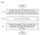
- FIG. 6 illustrates a flowchart illustrating a disparity estimation method according to example embodiments.
- the disparity estimation method according to example embodiments may be performed with reference to the disparity estimation system 500 illustrated in FIG. 5 .
- the disparity estimation method will be described with reference to FIG. 6 by describing a process where each operation is performed by the disparity estimation system 500.
- the disparity estimation system 500 may acquire N images of a previous frame, disparity maps with respect to each of the N images, and N images of a current frame. A plurality of images with respect to a plurality of viewpoints may be inputted for each frame. The disparity estimation system 500 may further acquire a plurality of images with respect to the previous frame, a plurality of disparity maps generated in the previous frame, and a plurality of images with respect to the current frame.
- the additional acquisition is for considering a temporal consistency in addition to a spatial consistency, and a temporally consistent disparity map may be generated through a temporal smoothness.
- the disparity estimation system 500 may set an energy function.
- the energy function may be classified into a region including a motion of an object and a region excluding the motion of the object. Further, the energy function may be set differently depending on the region.
- the region excluding the motion of the object may include a region where a color difference between proximate frames is less than a predetermined threshold value.
- the disparity estimation system 500 may set the energy function to include the temporal smoothness term with respect to a region where the color difference between proximate frames is less than the predetermined threshold value.
- the disparity estimation system 500 may set the energy function to exclude the temporal smoothness term with respect to a region where the color difference is greater than or equal to the predetermined threshold value. For example, in a case of a boundary region of an active object, a boundary may crack due to the temporal smoothness, and thus, the disparity estimation system 500 may set the energy function to exclude the temporal smoothness term with respect to the region including the motion of the object.
- the energy function may be set differently for a first frame and a subsequent frame.
- the disparity estimation system 500 may set the energy function to exclude the temporal smoothness term with respect to the first frame, and may set the energy function to include the temporal smoothness term with respect to the second frame and the subsequent frame, since the temporal smoothness term may be defined using both of a current frame and a previous frame, and the previous frame of the first frame may not exist.
- the disparity estimation system 500 may set the energy function satisfying the above conditions.
- the disparity estimation system 500 may estimate a disparity through a process of optimizing energy with respect to a disparity assignment using the energy function.
- the disparity estimation system 500 may estimate the disparity through the process of optimizing energy with respect to the disparity assignment using the energy function set in operation 620.
- the disparity estimation system 500 may use the energy function including the temporal smoothness term with respect to the frame after the first frame, and with respect to the region excluding the motion of the object in an image of a frame.
- the temporal smoothness term may constrain a difference in the disparity with respect to pixels present at the same location at the same point in time between proximate frames with respect to inputted images.
- the temporal smoothness term may be calculated as Equation 4 based on a sum of values where each of the values is a minimum value between an absolute value of the difference in the disparity and a predetermined constant value, with respect to pixels present at the same location at the same point in time between proximate frames.
- an energy term may include a spatial smoothness term constraining the difference in the disparity with respect to neighboring pixels, a data term constraining a color difference between viewpoints, and the temporal smoothness term.
- Each term included in the energy function may be calculated with respect to the disparity assignment using the Markov random field as shown in Equation 4.
- the disparity estimation system 500 may use a graph cut to optimize the energy with respect to the disparity assignment.
- the graph cut may be performed using a graph where an edge is connected between pixels placed at the same position among pixels of a graph with respect to the previous frame and pixels of a graph with respect to a current frame.
- a single graph may be configured without connecting graphs of proximate frames, and the graph cut is performed by adding a constraint with respect to the temporal smoothness to an edge connected to a source or a sink on the single graph.
- the disparity estimation system 500 may estimate the disparity through a process of optimizing an energy with respect to the disparity assignment using an energy function including the data term and the spatial smoothness term.
- the disparity estimation system 500 may fix the disparity of the previous frame, and may estimate the disparity through a process of optimizing an energy with respect to the disparity assignment using an energy function including the data term, the spatial smoothness term, and the temporal smoothness term.
- a flickering effect of a screen may be reduced. Since a disparity map may be generated using only a previous frame during a rendering, a disparity may be promptly calculated in response to an input of a new frame, enabling a prompt rendering.
- the disparity estimation method may be recorded in non-transitory computer-readable media including program instructions to implement various operations embodied by a computer.
- the media may also include, alone or in combination with the program instructions, data files, data structures, and the like.
- Examples of non-transitory computer-readable media include magnetic media such as hard disks, floppy disks, and magnetic tape; optical media such as CD ROM disks and DVDs; magneto-optical media such as optical disks; and hardware devices that are specially configured to store and perform program instructions, such as read-only memory (ROM), random access memory (RAM), flash memory, and the like.
- Examples of the magnetic recording apparatus include a hard disk device (HDD), a flexible disk (FD), and a magnetic tape (MT).
- optical disk examples include a DVD (Digital Versatile Disc), a DVD-RAM, a CD-ROM (Compact Disc - Read Only Memory), and a CD-R (Recordable)/RW.
- program instructions include both machine code, such as produced by a compiler, and files containing higher level code that may be executed by the computer using an interpreter.
- the described hardware devices may be configured to act as one or more software modules in order to perform the operations of the above-described embodiments, or vice versa.
Landscapes
- Engineering & Computer Science (AREA)
- Computer Vision & Pattern Recognition (AREA)
- Physics & Mathematics (AREA)
- General Physics & Mathematics (AREA)
- Theoretical Computer Science (AREA)
- Multimedia (AREA)
- Signal Processing (AREA)
- Image Analysis (AREA)
- Image Processing (AREA)
- Compression Or Coding Systems Of Tv Signals (AREA)
- Testing, Inspecting, Measuring Of Stereoscopic Televisions And Televisions (AREA)
Applications Claiming Priority (1)
| Application Number | Priority Date | Filing Date | Title |
|---|---|---|---|
| KR1020100102927A KR101669840B1 (ko) | 2010-10-21 | 2010-10-21 | 다시점 비디오로부터 일관성 있는 변이를 추정하는 변이 추정 시스템 및 방법 |
Publications (2)
| Publication Number | Publication Date |
|---|---|
| EP2444936A2 true EP2444936A2 (de) | 2012-04-25 |
| EP2444936A3 EP2444936A3 (de) | 2013-08-21 |
Family
ID=44910135
Family Applications (1)
| Application Number | Title | Priority Date | Filing Date |
|---|---|---|---|
| EP11185725.6A Withdrawn EP2444936A3 (de) | 2010-10-21 | 2011-10-19 | Disparitätseinschätzungssystem, Vorrichtung und Verfahren zur Einschätzung der durchgehenden Disparität eines Videos mit mehreren Ansichten |
Country Status (3)
| Country | Link |
|---|---|
| US (1) | US20120098932A1 (de) |
| EP (1) | EP2444936A3 (de) |
| KR (1) | KR101669840B1 (de) |
Cited By (3)
| Publication number | Priority date | Publication date | Assignee | Title |
|---|---|---|---|---|
| JP2014064835A (ja) * | 2012-09-27 | 2014-04-17 | Fujifilm Corp | 画像処理装置および方法並びにプログラム |
| EP2869571A3 (de) * | 2013-10-31 | 2015-07-08 | Samsung Electronics Co., Ltd. | Mehrfach-Bildanzeigevorrichtung und Steuerungsverfahren dafür |
| WO2015190327A1 (en) * | 2014-06-12 | 2015-12-17 | Toyota Jidosha Kabushiki Kaisha | Disparity image generating device, disparity image generating method, and image |
Families Citing this family (11)
| Publication number | Priority date | Publication date | Assignee | Title |
|---|---|---|---|---|
| US9113043B1 (en) * | 2011-10-24 | 2015-08-18 | Disney Enterprises, Inc. | Multi-perspective stereoscopy from light fields |
| US9165401B1 (en) | 2011-10-24 | 2015-10-20 | Disney Enterprises, Inc. | Multi-perspective stereoscopy from light fields |
| JP2015146526A (ja) * | 2014-02-03 | 2015-08-13 | ソニー株式会社 | 画像処理装置および方法、並びにプログラム |
| EP3016076A1 (de) | 2014-10-31 | 2016-05-04 | Thomson Licensing | Verfahren und Vorrichtung zur Entfernung von Ausreißern aus einer Hauptansicht einer Szene während der 3D-Szenen-Rekonstruktion |
| US9769453B2 (en) | 2015-02-13 | 2017-09-19 | Nokia Technologies Oy | Flicker reduction in 3D imaging |
| KR102415505B1 (ko) * | 2015-12-14 | 2022-07-01 | 삼성전자주식회사 | 스테레오 영상 매칭 방법 및 장치 |
| WO2017143550A1 (en) * | 2016-02-25 | 2017-08-31 | SZ DJI Technology Co., Ltd. | Imaging system and method |
| CN107689060A (zh) * | 2016-08-03 | 2018-02-13 | 北京三星通信技术研究有限公司 | 目标对象的视觉处理方法、装置及基于视觉处理的设备 |
| CN108510536B (zh) * | 2017-02-28 | 2021-09-21 | 富士通株式会社 | 多视点图像的深度估计方法和深度估计设备 |
| CN109242901B (zh) * | 2017-07-11 | 2021-10-22 | 深圳市道通智能航空技术股份有限公司 | 应用于三维相机的图像校准方法和装置 |
| US10803606B2 (en) * | 2018-07-19 | 2020-10-13 | National Taiwan University | Temporally consistent belief propagation system and method |
Family Cites Families (7)
| Publication number | Priority date | Publication date | Assignee | Title |
|---|---|---|---|---|
| US6744923B1 (en) * | 1999-08-30 | 2004-06-01 | Cornell Research Foundation, Inc. | System and method for fast approximate energy minimization via graph cuts |
| US7778328B2 (en) * | 2003-08-07 | 2010-08-17 | Sony Corporation | Semantics-based motion estimation for multi-view video coding |
| KR100800660B1 (ko) * | 2006-09-21 | 2008-02-01 | 삼성전자주식회사 | 파노라마 영상 촬영 장치 및 방법 |
| CN101933335B (zh) * | 2008-01-29 | 2012-09-05 | 汤姆森特许公司 | 将二维图像数据转换为立体图像数据的方法和系统 |
| WO2009145749A1 (en) * | 2008-05-28 | 2009-12-03 | Thomson Licensing | System and method for depth extraction of images with forward and backward depth prediction |
| US20110080466A1 (en) * | 2009-10-07 | 2011-04-07 | Spatial View Inc. | Automated processing of aligned and non-aligned images for creating two-view and multi-view stereoscopic 3d images |
| US8432434B2 (en) * | 2011-07-08 | 2013-04-30 | Mitsubishi Electric Research Laboratories, Inc. | Camera and method for focus based depth reconstruction of dynamic scenes |
-
2010
- 2010-10-21 KR KR1020100102927A patent/KR101669840B1/ko not_active Expired - Fee Related
-
2011
- 2011-10-19 EP EP11185725.6A patent/EP2444936A3/de not_active Withdrawn
- 2011-10-21 US US13/278,891 patent/US20120098932A1/en not_active Abandoned
Non-Patent Citations (1)
| Title |
|---|
| None |
Cited By (4)
| Publication number | Priority date | Publication date | Assignee | Title |
|---|---|---|---|---|
| JP2014064835A (ja) * | 2012-09-27 | 2014-04-17 | Fujifilm Corp | 画像処理装置および方法並びにプログラム |
| EP2869571A3 (de) * | 2013-10-31 | 2015-07-08 | Samsung Electronics Co., Ltd. | Mehrfach-Bildanzeigevorrichtung und Steuerungsverfahren dafür |
| US9105133B2 (en) | 2013-10-31 | 2015-08-11 | Samsung Electronics Co., Ltd. | Multi view image display apparatus and control method thereof |
| WO2015190327A1 (en) * | 2014-06-12 | 2015-12-17 | Toyota Jidosha Kabushiki Kaisha | Disparity image generating device, disparity image generating method, and image |
Also Published As
| Publication number | Publication date |
|---|---|
| US20120098932A1 (en) | 2012-04-26 |
| EP2444936A3 (de) | 2013-08-21 |
| KR101669840B1 (ko) | 2016-10-28 |
| KR20120041464A (ko) | 2012-05-02 |
Similar Documents
| Publication | Publication Date | Title |
|---|---|---|
| EP2444936A2 (de) | Disparitätseinschätzungssystem, Vorrichtung und Verfahren zur Einschätzung der durchgehenden Disparität eines Videos mit mehreren Ansichten | |
| US9582928B2 (en) | Multi-view rendering apparatus and method using background pixel expansion and background-first patch matching | |
| EP2608148B1 (de) | Verfahren und Vorrichtung zur Erzeugung einer Mehrfachansicht | |
| JP4644669B2 (ja) | マルチビュー画像の生成 | |
| JP5425897B2 (ja) | 前方及び後方の深度予測を伴う、画像の深度抽出のシステム及び方法 | |
| US8553972B2 (en) | Apparatus, method and computer-readable medium generating depth map | |
| US8073292B2 (en) | Directional hole filling in images | |
| US9007435B2 (en) | Real-time depth-aware image enhancement system | |
| US9117295B2 (en) | Refinement of depth maps by fusion of multiple estimates | |
| KR101502362B1 (ko) | 영상처리 장치 및 방법 | |
| US9159154B2 (en) | Image processing method and apparatus for generating disparity value | |
| EP2169619A2 (de) | Umwandlungsverfahren und -vorrichtung mit Tiefenkartenerzeugung | |
| US8803947B2 (en) | Apparatus and method for generating extrapolated view | |
| US8441521B2 (en) | Method and apparatus for determining view of stereoscopic image for stereo synchronization | |
| US8634675B2 (en) | Apparatus and method for generating extrapolated view based on image resizing | |
| CN102077246A (zh) | 利用运动补偿进行图像的深度提取的系统和方法 | |
| JP2011504262A (ja) | 領域ベースのフィルタリングを使用する奥行マップ抽出のためのシステムおよび方法 | |
| US20120050283A1 (en) | Rendering apparatus and method for generating multi-views | |
| KR101249236B1 (ko) | 깊이 인식 | |
| JP4892113B2 (ja) | 画像処理方法及び装置 | |
| US20120044244A1 (en) | Method for Image Processing and an Apparatus Thereof | |
| US8879872B2 (en) | Method and apparatus for restoring resolution of multi-view image | |
| KR101626679B1 (ko) | 2d 영상으로부터 입체 영상을 생성하는 방법 및 이를 기록한 기록 매체 |
Legal Events
| Date | Code | Title | Description |
|---|---|---|---|
| AK | Designated contracting states |
Kind code of ref document: A2 Designated state(s): AL AT BE BG CH CY CZ DE DK EE ES FI FR GB GR HR HU IE IS IT LI LT LU LV MC MK MT NL NO PL PT RO RS SE SI SK SM TR |
|
| AX | Request for extension of the european patent |
Extension state: BA ME |
|
| PUAI | Public reference made under article 153(3) epc to a published international application that has entered the european phase |
Free format text: ORIGINAL CODE: 0009012 |
|
| RAP1 | Party data changed (applicant data changed or rights of an application transferred) |
Owner name: SAMSUNG ELECTRONICS CO., LTD. |
|
| PUAL | Search report despatched |
Free format text: ORIGINAL CODE: 0009013 |
|
| RIC1 | Information provided on ipc code assigned before grant |
Ipc: G06T 7/00 20060101AFI20130709BHEP |
|
| AK | Designated contracting states |
Kind code of ref document: A3 Designated state(s): AL AT BE BG CH CY CZ DE DK EE ES FI FR GB GR HR HU IE IS IT LI LT LU LV MC MK MT NL NO PL PT RO RS SE SI SK SM TR |
|
| AX | Request for extension of the european patent |
Extension state: BA ME |
|
| 17P | Request for examination filed |
Effective date: 20140204 |
|
| RBV | Designated contracting states (corrected) |
Designated state(s): AL AT BE BG CH CY CZ DE DK EE ES FI FR GB GR HR HU IE IS IT LI LT LU LV MC MK MT NL NO PL PT RO RS SE SI SK SM TR |
|
| 17Q | First examination report despatched |
Effective date: 20170213 |
|
| STAA | Information on the status of an ep patent application or granted ep patent |
Free format text: STATUS: THE APPLICATION IS DEEMED TO BE WITHDRAWN |
|
| 18D | Application deemed to be withdrawn |
Effective date: 20180501 |