EP2452760B1 - Profiliermaschine sowei Kupplungsständer für eine solche Maschine - Google Patents
Profiliermaschine sowei Kupplungsständer für eine solche Maschine Download PDFInfo
- Publication number
- EP2452760B1 EP2452760B1 EP20100014654 EP10014654A EP2452760B1 EP 2452760 B1 EP2452760 B1 EP 2452760B1 EP 20100014654 EP20100014654 EP 20100014654 EP 10014654 A EP10014654 A EP 10014654A EP 2452760 B1 EP2452760 B1 EP 2452760B1
- Authority
- EP
- European Patent Office
- Prior art keywords
- coupling
- profiling machine
- counterparts
- stands
- working
- Prior art date
- Legal status (The legal status is an assumption and is not a legal conclusion. Google has not performed a legal analysis and makes no representation as to the accuracy of the status listed.)
- Not-in-force
Links
- 238000010168 coupling process Methods 0.000 title claims description 195
- 230000008878 coupling Effects 0.000 title claims description 192
- 238000005859 coupling reaction Methods 0.000 title claims description 192
- 238000000034 method Methods 0.000 claims description 7
- 239000002184 metal Substances 0.000 claims description 6
- 230000005540 biological transmission Effects 0.000 description 7
- 238000003780 insertion Methods 0.000 description 4
- 230000037431 insertion Effects 0.000 description 4
- 238000006073 displacement reaction Methods 0.000 description 2
- 241001295925 Gegenes Species 0.000 description 1
- 230000002411 adverse Effects 0.000 description 1
- 230000006835 compression Effects 0.000 description 1
- 238000007906 compression Methods 0.000 description 1
- 238000010276 construction Methods 0.000 description 1
- 238000011161 development Methods 0.000 description 1
- 230000018109 developmental process Effects 0.000 description 1
- 238000009434 installation Methods 0.000 description 1
- 238000004519 manufacturing process Methods 0.000 description 1
- 238000003825 pressing Methods 0.000 description 1
- 238000005096 rolling process Methods 0.000 description 1
- 210000002023 somite Anatomy 0.000 description 1
Images

Classifications
-
- B—PERFORMING OPERATIONS; TRANSPORTING
- B21—MECHANICAL METAL-WORKING WITHOUT ESSENTIALLY REMOVING MATERIAL; PUNCHING METAL
- B21D—WORKING OR PROCESSING OF SHEET METAL OR METAL TUBES, RODS OR PROFILES WITHOUT ESSENTIALLY REMOVING MATERIAL; PUNCHING METAL
- B21D5/00—Bending sheet metal along straight lines, e.g. to form simple curves
- B21D5/06—Bending sheet metal along straight lines, e.g. to form simple curves by drawing procedure making use of dies or forming-rollers, e.g. making profiles
- B21D5/08—Bending sheet metal along straight lines, e.g. to form simple curves by drawing procedure making use of dies or forming-rollers, e.g. making profiles making use of forming-rollers
Definitions
- the invention relates to a coupling stand for a profiling machine for longitudinally forming a metal strip or initial profile in a profile or tube by means of a plurality of Rollumformtechnikmaschineen according to the preamble of claim 1, and a profiling machine with such coupling stands and a corresponding method.
- At least part of the roll forming tools of a profiling machine of the present type is combined to form a plurality of tool groups arranged one behind the other in the working direction, each of which is held in a frame and forms a forming station with it. At least a part of the rolling forming tools arranged in a forming station is seated on work shafts mounted in the frame, which are provided with coupling elements leading out laterally from the stand.
- clutch stand are arranged, on the one hand have coupling counterparts to the coupling elements of the working shafts and on the other hand connections for a drive system of the profiling to transmit torque from the drive system to the working shafts.
- the coupling elements of the working shafts are usually made of coupling pins or sleeves, while the coupling stand is equipped with sleeves or pins which engage positively in the coupling pins or sleeves of the working shafts.
- the torque transmission is usually carried out by means of variable length propeller shafts.
- Profiling machines are able to produce virtually endless profiles or tubes of various cross-sectional shapes from a metal strip or an output profile.
- a multiplicity of roll forming tools are used for this purpose, which are grouped together in typically 20 to 30 forming stations arranged in line one behind the other. If a different profile shape is to be produced on one and the same profiling machine, a multiplicity of roll forming tools must accordingly be exchanged.
- a coupling stand is provided in a profiling machine of the type described above between the forming stations and the drive system, which can engage and disengage the working shafts, so that the roll forming tools together with their working shafts can be exchanged as a unit, without having to move the framework relative to the machine base or with respect to a framework support plate.
- An exchange of the roll forming tools without subsequent lengthy adjustments, especially in the axis parallel to the working waves direction, is possible by the previous uncoupling of the drive system. This saves time when converting a Profiliermaschine to another profile shape and thus reduces adverse production stoppages.
- a profiling machine of the present type is in the EP 0 365 976 B1 described.
- laterally movable clutch stand together move away from the forming rollers to release the working shafts. After replacing them, the coupling stands are again almost to their engaged initial position to the forming stations moved up and determined the possibly changed installation height of the working shafts. Then the coupling counterparts are moved vertically on the coupling uprights to adjust their height to the height of the respective working shaft.
- the clutch stands are further moved together to the forming stations to bring the coupling elements and the coupling counterparts into engagement, whereby the coupling process is terminated.
- a gear block of the drive system is moved with the coupling stands, or the changing distance between the coupling stands and the drive system is compensated by variable length drive shafts.
- the present invention seeks to provide improved coupling stand available to further improve a profiling machine of the type described above with regard to their flexibility, and to propose such an improved profiling machine and a corresponding method.
- the coupling stands are no longer displaceable only as a whole towards and away from the working shafts, but the coupling counterparts for the working shafts of the stands with their associated drive system connections are seated individually or in groups on separate coupling sections of the coupling stands according to the invention , These coupling sections are independently movable from each other. In this case, alla Kupplungsabsuhnitte can be moved separately be. However, if only two coupling sections are involved, it may be implemented so that one coupling section is movable independently of the remainder of the coupling stand while the other coupling section is moved together with the remainder of the coupling stand; In this case, the clutch stand as a whole, as was the case in the prior art, would be movable.
- the coupling stand may comprise a stationary support member having two or more coupling sections mounted movably thereon so that ultimately only the coupling sections move to couple or uncouple individual working shafts while the support member the coupling stand is arranged stationary relative to the associated frame and carries guides and the drives for the movable coupling sections.
- the Ankuppelvorgang took place so far, for example, in the prior art after the EP 0 365 976 B1 as described above by axial nesting of the coupling elements and the coupling counterparts on the working shafts or on the coupling stanchions, so that they then interlock and can transmit a torque.
- the coupling counterparts are in turn connected to the drive system.
- the overload protection by the pneumatic drive of the coupling sections not only replaces the previous overload protection by resilient coupling elements and coupling counterparts when coupling, but also provides in the opposite direction, ie when uncoupling, an overload protection.
- the coupling elements and the coupling counterparts can often not be separated from each other, since they are braced against each other in the direction of rotation.
- the existing by the pneumatic drive overload protection prevents this, that the coupling stand or the coupling section pulls obliquely, because about the coupling elements and coupling counterparts do not come apart.
- the pneumatic drive brings only a resilient bias on the clutch stand, so that it moves only when the coupling elements and the coupling counterparts separate from each other, for example by a short reversing of the drive system or by a manually applied vibration.
- the coupling stand of the profiling machine according to the invention are provided with vertical drive devices for changing the height of the coupling counterparts, these vertical drive devices are preferably also pneumatic actuators.
- the vertical drive devices can be used to adjust the vertical position of the coupling counterparts in the coupling stand to approximately changed vertical positions of the working shafts, for example when the roll forming tools of the forming station have been replaced.
- the coupling counterparts and / or the coupling elements are each end provided with insertion aids, in particular with conically shaped end pieces.
- the coupling elements are designed as coupling sleeves, and the coupling counterparts as coupling sleeves which can be positively inserted into these sleeves, this can be realized in this way; that the coupling pins are provided at the end with a cylindrical end piece whose outer circumference is smaller than the outer circumference of the form-locking elements of the coupling pin, and in that the coupling sleeves are provided at the end with a conically shaped insertion section.
- the present invention is preferably further developed such that the coupling counterpart and the associated connection for the drive system sitting in a bearing in the coupling portion which is spring-loaded slightly orthogonal to the working shaft axis movable; It can therefore be moved horizontally by a millimeter against a spring force, for example, to bring the coupling element of the respective working shaft with the coupling counterpart of the coupling stand exactly in alignment.
- the spring-loaded displaceability of the bearing in the coupling sections greatly facilitates the coupling process.
- FIGS. 1 and 2 show in a schematic cross section and a perspective view of the same part of an inventively designed profiling, namely a forming station 1 with an upper working shaft 2 and a lower working shaft 3, which serve for receiving and storing (not shown here) Rollumformwerkmaschineen.
- the two working waves 2, 3 are mounted vertically displaceable in a frame 4.
- the framework 4 is fixedly attached to a (not shown) machine frame.
- the working shafts 2, 3 can be vertically adjusted in the frame 4 in order to adapt to different Rollumformwerkmaschinemaschinee can.
- a transmission block 9 of a drive system is arranged on a gear carrier 10, from which a torque is to be transmitted to the working shafts 2, 3. This is done via two propeller shafts 15, which connect the gear block 9 with the working shafts 2, 3 torsionally rigid.
- a coupling stand 11 is arranged, with the aid of the propeller shafts 15, and thus the transmission block 9 of the drive system, coupled to the working shafts 2, 3 of the forming station 1 or decoupled from them can be without having to move the gear block 9 or the frame 4.
- the working shafts 2, 3 run out towards the gear block beyond the framework 4 into coupling elements 13, of which in the present illustration only the lower coupling element 13 is visible, and which are designed here as coupling pins.
- the coupling stand 11 has two coupling sections, an upper coupling section 5 and a lower coupling section 6, each in a bearing housing 14 to the frame 4 towards a (not visible here) coupling counterpart 12, namely a coupling sleeve for the coupling element 13, and on the opposite Side, the transmission block 9 through, in each case one, designed as a telescopically length-adjustable propeller shaft 15 formed connection for the transmission block 9.
- the torque from the transmission block 9 is thus transmitted via the propeller shafts 15 and the coupling counterparts 12 designed as a coupling sleeve, which are mounted in the bearing housing 14, on the coupling elements 13 designed as a coupling pin and thus on the working shafts 2, 3.
- the upper working shaft 2 of the present embodiment is coupled to the transmission block 9 and thus to the drive system of the profiling machine, while the lower working shaft 3 is uncoupled.
- This movement of the two coupling sections 5 and 6 is effected by an upper 16 and a lower pneumatic cylinder 17, the piston rods 18, the respective coupling sections 5, 6 move, and supported on height-adjustable on the support member 7 mounted support plates 19.
- sliding rails 20, 21 are provided which are slidably held in corresponding receptacles of the support plates 19.
- the mounted in the bearing housing 14 coupling counterparts 12 can move within the bearing housing 14 by about 1 - 2 mm in an orthogonal to the axes of the working shafts 2, 3, so that a small offset of the working shaft axis to the coupling counterpart 12 horizontally and / or vertically compensated can be and the engagement process is still possible. If the coupling elements 13 and / or the coupling counterparts 12 are provided with corresponding insertion bevels, the evasive movement of the coupling counterpart 12 in the bearing housing 14 can take place automatically.
- the flexibility of a profiling machine is significantly increased, and the preferred embodiments of the invention simplify and accelerate coupling and uncoupling operations, facilitating and thus supporting the use of increased flexibility.
Landscapes
- Engineering & Computer Science (AREA)
- Mechanical Engineering (AREA)
- Bending Of Plates, Rods, And Pipes (AREA)
- Automatic Assembly (AREA)
Description
- Die Erfindung betrifft einen Kupplungsständer für eine Profiliermaschine zum Längsumformen eines Metallbandes oder Ausgangsprofils in ein Profil oder Rohr mittels einer Mehrzahl von Rollumformwerkzeugen nach dem Oberbegriff des Anspruchs 1, sowie eine Profiliermaschine mit solchen Kupplungsständern und ein entsprechendes Verfahren.
- Zumindest ein Teil der Rollumformwerkzeuge einer Profiliermaschine der vorliegenden Art ist zu mehreren, in Arbeitsrichtung hintereinander angeordneten Werkzeuggruppen zusammengefasst, die jeweils in einem Gerüst gehalten sind und mit diesem jeweils eine Umformstation bilden. Wenigstens ein Teil der in einer Umformstation angeordneten Rollumformwerkzeuge sitzt auf im Gerüst gelagerten Arbeitswellen, die mit seitlich aus dem Gerüst herausführenden Kupplungselementen versehen sind. Neben den Gerüsten sind Kupplungsständer angeordnet, die einerseits Kupplungsgegenstücke zu den Kupplungselementen der Arbeitswellen und andererseits Anschlüsse für ein Antriebssystem der Profiliermaschine aufweisen, um ein Drehmoment vom Antriebssystem auf die Arbeitswellen zu übertragen. Die Kupplungselemente der Arbeitswellen bestehen üblicherweise aus Kupplungszapfen oder Hülsen, während der Kupplungsständer mit Hülsen bzw. Zapfen ausgestattet ist, die formschlüssig in die Kupplungszapfen bzw. -hülsen der Arbeitswellen eingreifen.
- Um bei solchen Profiliermaschinen die Arbeitswellen der Umformstationen vom Antriebssystem abkuppeln oder an dieses ankuppeln zu können, ist es im Stand der Technik bekannt, dass die Kupplungsständer zu den Gerüsten hin oder von diesen weg bewegbar ausgebildet werden, so dass die Kupplungselemente der Arbeitswellen und die Kupplungsgegenstücke am Kupplungsständer wahlweise in Eingriff kommen oder aus ihrem Eingriff herausgenommen werden. Im Falle von Kupplungszapfen und Hülsen ist hierzu eine axiale Verschiebung nötig.
- Zwischen dem Antriebssystem der Profiliermaschine und den Kupplungsständern erfolgt die Drehmomentübertragung üblicherweise mittels längenveränderlicher Gelenkwellen.
- Profiliermaschinen sind in der Lage, aus einem Metallband oder einem Ausgangsprofil quasi endlos Profile oder Rohre unterschiedlichster Querschnittsformen zu fertigen. Je nach Profilform kommen hierfür eine Vielzahl von Rollumformwerkzeugen zum Einsatz, die in typischerweise 20 bis 30 in Linie hintereinander angeordneten Umformstationen gruppenweise zusammengefasst sind. Wenn auf ein und derselben Profiliermaschine nun eine andere Profilform produziert werden soll, muss dementsprechend eine Vielzahl von Rollumformwerkzeugen ausgewechselt werden. Um hierfür nicht die Gerüste der einzelnen Umformstationen in der Maschine demontieren zu müssen, ist bei einer Profiliermaschine der oben beschriebenen Art zwischen den Umformstationen und dem Antriebssystem jeweils ein Kupplungsständer vorgesehen, der die Arbeitswellen ein- und auskuppeln kann, so dass die Rollformwerkzeuge mitsamt ihren Arbeitswellen als Baueinheit ausgetauscht werden können, und zwar ohne das Gerüst gegenüber dem Maschinenuntergestell oder gegenüber einer Gerüst-Trägerplatte verschieben zu müssen. Ein Austausch der Rollformwerkzeuge ohne anschließende langwierige Justierarbeiten, insbesondere in zu den Arbeitswellen achsparalleler Richtung, ist durch das vorherige Abkuppeln des Antriebssystems möglich. Dies spart Zeit beim Umrüsten einer Profiliermaschine auf eine andere Profilform und vermindert damit nachteilige Produktionsstillstände.
- Eine Profiliermaschine der vorliegenden Art ist in der
EP 0 365 976 B1 beschrieben. Um die dort gestellte Aufgabe zu lösen, Rollumformwerkzeug-Paare in den Umformstationen schnell und vollautomatisch auswechseln zu können, so dass die Stillstandzeit der Profiliermaschine auf ein Minimum begrenzt wird und dennoch nacheinander Profile unterschiedlichster Querschnitte hergestellt werden können, wurde dort vorgeschlagen, seitlich bewegbare Kupplungsständer gemeinsam von den Umformrollen weg zu verschieben, um die Arbeitswellen freizugeben. Nach dem Auswechseln derselben werden die Kupplungsständer wieder bis fast an ihre eingekuppelte Ausgangsstellung an die Umformstationen herangefahren und die gegebenenfalls veränderte Einbauhöhe der Arbeitswellen ermittelt. Sodann werden die Kupplungsgegenstücke auf den Kupplungsständern vertikal verfahren, um deren Höhe auf die Höhe der jeweiligen Arbeitswelle anzupassen. Danach werden die Kupplungsständer weiter gemeinsam an die Umformstationen herangefahren, um die Kupplungselemente und die Kupplungsgegenstücke in Eingriff zu bringen, wodurch der Ankuppelvorgang beendet wird. Hierbei wird entweder ein Getriebeblock des Antriebssystems mit den Kupplungsständern mitbewegt, oder der sich verändernde Abstand zwischen den Kupplungsständern und dem Antriebssystem wird von längenveränderlichen Gelenkwellen ausgeglichen. - Insbesondere in Erprobungsphasen einer Profiliermaschine ist es nun oft wünschenswert, einzelne Umformstationen antriebslos zu stellen, was im Stand der Technik allerdings nur dadurch erzielt werden kann, dass die Kupplungsgegenstücke in den entsprechenden Kupplungsständern durch Leerhülsen ersetzt werden, die kein Drehmoment auf die Arbeitswellen übertragen.
- Ausgehend von diesem Stand der Technik liegt der vorliegenden Erfindung die Aufgabe zugrunde, verbesserte Kupplungsständer zur Verfügung zu stellen, um eine Profiliermaschine der oben beschriebenen Art hinsichtlich ihrer Flexibilität weiter zu verbessern, sowie eine so verbesserte Profiliermaschine und ein entsprechendes Verfahren vorzuschlagen.
- Gelöst ist diese Aufgabe durch einen Kupplungsständer mit den Merkmalen des Anspruchs 1, eine Profiliermaschine mit den Merkmalen des Anspruchs 2 sowie durch ein Verfahren mit den Merkmalen des Anspruchs 11. Bevorzugte Weiterbildungen der Erfindung finden sich in den Ansprüchen 3 bis 10, sowie 12.
- Gemäß der vorliegenden Erfindung sind die Kupplungsständer demnach nicht mehr nur als Ganzes zu den Arbeitswellen hin und von diesen weg verschiebbar, sondern die Kupplungsgegenstücke für die Arbeitswellen der Gerüste mit den diesen zugeordneten Anschlüssen für das Antriebssystem sitzen einzeln oder in Gruppen auf separaten Kupplungsabschnitten der erfindungsgemäßen Kupplungsständer, wobei diese Kupplungsahschnitte unabhängig Voneinander bewegbar sind. Hierbei Können alla Kupplungsabsuhnitte separat bewegbar sein. Wenn es sich lediglich um zwei Kupplungsabschnitte handelt, kann dies jedoch auch so umgesetzt werden, dass ein Kupplungsabschnitt unabhängig vom Rest des Kupplungsständers bewegbar ist, während der andere Kupplungsabschnitt zusammen mit dem Rest des Kupplungsständers bewegt wird; in diesem Fall wäre der Kupplungsständer als Ganzes, wie dies auch im Stand der Technik der Fall war, bewegbar. Im ersteren Fall, und dies ist im Rahmen der vorliegenden Erfindung bevorzugt, kann allerdings der Kupplungsständer ein ortsfestes Tragelement mit zwei oder mehr daran beweglich angebrachten Kupplungsabschnitten umfassen, so dass sich letztendlich nur die Kupplungsabschnitte bewegen, um einzelne Arbeitswellen anzukuppeln oder abzukuppeln, während das Tragelement des Kupplungsständers gegenüber dem zugeordneten Gerüst ortsfest angeordnet ist und Führungen sowie die Antriebe für die bewegbaren Kupplungsabschnitte trägt.
- Selbstverständlich können im Rahmen der vorliegenden Erfindung alle Kupplungsabschnitte eines Kupplungsständers gemeinsam zu den Arbeitswellen hin und von diesen weg bewegt werden, so dass sich eine Arbeitsweise ergibt, wie sie aus dem Stand der Technik bekannt ist. Im Rahmen der vorliegenden Erfindung ist es aber eben auch möglich, nur einzelne Arbeitswellen anzukuppeln oder ausgewählte Arbeitswellen abgekuppelt zu lassen oder nur diejenigen Arbeitswellen anzukuppeln, die für einen bestimmten Vorgang angetrieben werden sollen. Dies erhöht die Flexibilität der Profiliermaschine enorm.
- Nach einer besonders bevorzugten Weiterbildung der vorliegenden Erfindung werden die beweglichen Kupplungsabschnitte der Kupplungsständer mittels pneumatischer Antriebe bewegt, die vorzugsweise im wesentlichen aus mindestens einer pneumatisch betriebenen Kolben-Zylinder-Einheit und einer Führungseinrichtung pro beweglichem Kupplungsabschnitt bestehen. Dies bringt mehrere Vorteile mit sich:
- Pneumatische Antriebe sind kostengünstig sowie unaufwändig einzeln ansteuerbar. Ein pneumatischer Antrieb der Kupplungsabschnitte hat daneben den weiteren großen Vorteil, dass er federnde Eigenschaften besitzt und somit bereits mit einem integrierten Überlastschutz versehen ist. Soweit also beim Ankuppeln einer Arbeitswelle deren Kupplungselement relativ zum Kupplungsgegenstück am Kupplungsabschnitt in Drehrichtung versetzt ist, die Formschluss herstellenden Teile dieser Kupplungselemente also nicht fluchten, bleibt der Kupplungsabschnitt und dessen pneumatischer Antrieb stehen. Es ist nicht zu befürchten, dass der Kupplungsständer durch den pneumatischen Antrieb beschädigt wird, wenn ein Eingreifen der Kupplungselemente und der Kupplungsgegenstücke nicht möglich ist; vielmehr erzeugt der pneumatische Antrieb dann lediglich eine Federkraft auf den Kupplungsabschnitt, der ihn elastisch gegen das Gerüst der Umformstation vorspannt, so dass er sich weiter bewegt, sobald die Kupplungselemente und Kupplungsgegenstücke durch Betätigen des Antriebssystems fluchtend aufeinander zu liegen kommen und einrücken. Hierdurch erübrigen sich die im Stand der Technik bislang notwendig gewesenen, aufwändigen Überlastsicherungen:
- Der Ankuppelvorgang erfolgte bislang beispielsweise im Stand der Technik nach der
EP 0 365 976 B1 wie eingangs beschrieben durch axiales Ineinanderstecken der Kupplungselemente und der Kupplungsgegenstücke an den Arbeitswellen bzw. an den Kupplungsständern, so dass diese dann ineinandergreifen und ein Drehmoment übertragen können. Nach dem Austausch der Arbeitswellen ist jedoch nicht gewährleistet, dass deren Kupplungselemente sich in einer Rotationswinkelstellung befinden, in der sie in einen in Rotationsrichtung formschlüssigen Eingriff mit den Kupplungsgegenstücken der Kupplungsständer gelangen können, wobei die Kupplungsgegenstücke ihrerseits mit dem Antriebssystem verbunden sind. Treffen jedoch bei der axialen Verschiebung der Kupplungsständer die Kupplungselemente und die Kupplungsgegenstücke in einer Rotationswinkelstellung aufeinander, in der sie nicht ineinandergreifen können, führt dies zu einer Störung im Ankuppelvorgang und schlimmstenfalls zu einem Verziehen des Kupplungsständers. In derEP 0 365 976 B1 wurde daher vorgeschlagen, entweder die Kupplungselemente oder die Kupplungsgegenstücke an den Arbeitswellen bzw. den Kupplungsständer federbelastet axial nachgiebig auszubilden, so dass sie bei einem in Drehrichtung versetzten Aufeinandertreffen axial nachgeben können, ohne eine Störung des Einkuppelvorgangs zu verursachen. Beim Anlaufen des Antriebssystems oder durch ein kurzes Betätigen desselben verändern sich die Rotationswinkelstellungen der Kupplungselemente und der Gegenstücke zueinander, so dass in demjenigen Zeitpunkt, in dem ein Formschluss möglich ist, die Federkraft des federbelasteten Elements für ein Einrücken desselben in den Formschluss sorgt und der Ankuppelvorgang damit abgeschlossen ist. - Der Überlastschutz durch den erfindungsgemäßen pneumatischen Antrieb der Kupplungsabschnitte ersetzt jedoch nicht nur die bisherige Überlastsicherung durch federnde Kupplungselemente und Kupplungsgegenstücke beim Ankuppeln, sondern bietet darüber hinaus auch in der umgekehrten Richtung, also beim Abkuppeln, einen Überlastschutz. Insbesondere dann, wenn Umformstationen vom Antriebssystem abgekuppelt werden sollen, in denen sich ein Band bzw. Profil befindet, können die Kupplungselemente und die Kupplungsgegenstücke oft nicht voneinander gelöst werden, da sie in Rotationsrichtung gegeneinander verspannt sind. Der durch den pneumatischen Antrieb vorhandene Überlastschutz verhindert hierbei, dass der Kupplungsständer oder der Kupplungsabschnitt schief zieht, weil sich etwa die Kupplungselemente und Kupplungsgegenstücke nicht voneinander lösen. Denn auch in diesem Fall bringt der pneumatische Antrieb lediglich eine federnde Vorspannung auf den Kupplungsständer auf, so dass dieser sich erst dann bewegt, wenn sich die Kupplungselemente und die Kupplungsgegenstücke voneinander lösen, beispielsweise durch kurzes Reversieren des Antriebssystems oder auch durch eine manuell aufgebrachte Erschütterung.
- Weitere Vorteile ergeben sich, wenn die Kupplungsständer der erfindungsgemäßen Profiliermaschine mit Vertikal-Antriebsvorrichtungen zur Höhenveränderung der Kupplungsgegenstücke versehen sind, wobei diese Vertikal-Antriebsvorrichtungen vorzugsweise ebenfalls pneumatische Antriebe sind. Die Vertikal-Antriebsvorrichtungen können dazu verwendet werden, die vertikale Position der Kupplungsgegenstücke im Kupplungsständer auf etwa veränderte vertikale Positionen der Arbeitswellen anzupassen, beispielsweise wenn die Rollformwerkzeuge der Umformstation ausgewechselt worden sind.
- Soweit die Vertikal-Antriebsvorrichtungen zum Ausführen einer oszillierenden Auf- und Abbewegung der Kupplungsgegenstücke geeignet sind, ergibt sich nochmals eine erhebliche Verbesserung der erfindungsgemäßen Profiliermaschine gegenüber dem bisherigen Stand der Technik. Denn so kann das Ankuppeln unter Ausnutzung der überlastschützenden Eigenschaften des erfindungsgemäßen pneumatischen Antriebs ohne eine aufwändige Höhenjustierung der Kupplungsgegenstücke zu den Kupplungselementen der Arbeitswellen erfolgen. Vielmehr sorgt eine kleine oszillierende Auf- und Abbewegung der Kupplungsgegenstücke im Kupplungsständer beim Ankuppeln dafür, dass diese mit den jeweiligen Kupplungselementen der Arbeitswellen auch dann in Eingriff gelangen, wenn die Höhenjustierung zuvor nur grob erfolgte. Auch beim Abkuppeln kann eine solche geringfügige oszillierende Bewegung vorteilhaft sein, da sich hierdurch die Kupplungselemente und die Kupplungsgegenstücke leichter voneinander lösen.
- Für ein noch leichteres Ankuppeln kann insbesondere die oszillierende Auf- und Abbewegung der Kupplungsgegenstücke noch dadurch unterstützt werden, dass die Kupplungsgegenstücke und/oder die Kupplungselemente jeweils endseitig mit Einführhilfen versehen sind, insbesondere mit konisch geformten Endstücken. Wenn beispielsweise die Kupplungselemente, wie an sich üblich, als Kupplungshülsen, und die Kupplungsgegenstücke als in diese Hülsen formschlüssig einsteckbare Kupplungszapfen ausgebildet sind, kann dies derart realisiert werden; dass die Kupplungszapfen endseitig mit einem zylindrischen Endstück versehen sind, dessen Außenumfang kleiner ist als der Außenumfang der Formschluss bildenden Elemente des Kupplungszapfens, sowie dadurch, dass die Kupplungshülsen endseitig mit einem konisch geformten Einführabschnitt versehen sind.
- Aufgrund der hohen, in einer Profiliermaschine herrschenden Kräfte kommt es vor, dass sich Arbeitswellen zwischen zwei Ankuppelvorgängen orthogonal zu ihrer Achse, also horizontal und/oder vertikal geringfügig verstellen, beispielsweise zwischen einem Ankuppeln mit und einem Ankuppeln ohne in der Umformstation formstation eingelegtem Metallband, so dass die entsprechenden Kupplungselemente nicht mehr hundertprozentig mit den Kupplungsgegenstücken auf den Kupplungsabschnitten der Kupplungsständer fluchten. Dies erschwert naturgemäß das Einkuppeln. Für diesen Fall ist die vorliegende Erfindung bevorzugt solcherart weitergebildet, dass das Kupplungsgegenstück und der diesem zugeordnete Anschluss für das Antriebssystem in einem Lager im Kupplungsabschnitt sitzen, das federbelastet geringfügig orthogonal zur Arbeitswellenachse bewegbar ist; es kann also gegen eine Federkraft beispielsweise horizontal um einen Millimeter verschoben werden, um das Kupplungselement der betreffenden Arbeitswelle mit dem Kupplungsgegenstück des Kupplungsständers exakt in Flucht zu bringen. Insbesondere im Zusammenhang mit konisch geformten Endstücken der Kupplungselemente und Kupplungsgegenstücke, die Einführschrägen bilden, ist die federbelastete Verschiebbarkeit der Lagerung in den Kupplungsabschnitten eine große Erleichterung für den Kupplungsvorgang.
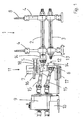
- Ein Ausführungsbeispiel für eine erfindungsgemäße Profiliermaschine mit einem erfindungsgemäßen Kupplungsständer ist im folgenden anhand der beigefügten Zeichnungen näher beschrieben und erläutert. Es zeigen:
- Figur 1
- eine schematische Darstellung eines Querschnitts einer Profiliermaschine mit einer Ansicht auf eine Umformstation, in teilweise angekuppeltem und teilweise abgekuppeltem Zustand;
- Figur 2
- eine perspektivische Darstellung des Ensembles aus Figur 1
- Die
Figuren 1 und2 zeigen in einem schematischen Querschnitt bzw. einer perspektivischen Ansicht denselben Teil einer erfindungsgemäß ausgestalteten Profiliermaschine, und zwar eine Umformstation 1 mit einer oberen Arbeitswelle 2 und einer unteren Arbeitswelle 3, die zur Aufnahme und zur Lagerung von (hier nicht dargestellten) Rollumformwerkzeugen dienen. Die beiden Arbeitswellen 2, 3 sind in einem Gerüst 4 vertikal verschiebbar gelagert. Das Gerüst 4 ist ortsfest an einem (nicht dargestellten) Maschinengestell befestigt. Mittels einer Höhenverstellung 8 können die Arbeitswellen 2, 3 im Gerüst 4 vertikal vertstellt werden, um sie an unterschiedliche Rollumformwerkzeuge anpassen zu können. - In etwa in Flucht mit den Achsen der Arbeitswellen 2, 3, ist auf einem Getriebeträger 10 ein Getriebeblock 9 eines Antriebssystems angeordnet, von dem ein Drehmoment auf die Arbeitswellen 2, 3 übertragen werden soll. Dies erfolgt über zwei Gelenkwellen 15, die den Getriebeblock 9 mit den Arbeitswellen 2, 3 torsionssteif verbinden.
- Zwischen dem Getriebeblock 9 mit seinen Gelenkwellen 15 und dem Gerüst 4 der Umformstation 1 ist ein Kupplungsständer 11 angeordnet, mit dessen Hilfe die Gelenkwellen 15, und damit der Getriebeblock 9 des Antriebssystems, an die Arbeitswellen 2, 3 der Umformstation 1 angekuppelt oder von diesen abgekuppelt werden kann, ohne den Getriebeblock 9 oder das Gerüst 4 bewegen zu müssen.
- Zu diesem Zweck laufen die Arbeitswellen 2, 3 zum Getriebeblock hin über das Gerüst 4 hinaus in Kupplungselemente 13 aus, von denen in der vorliegenden Darstellung nur das untere Kupplungselement 13 sichtbar ist, und die hier als Kupplungszapfen ausgebildet sind. Der Kupplungsständer 11 weist zwei Kupplungsabschnitte, einen oberen Kupplungsabschnitt 5 und einen unteren Kupplungsabschnitt 6 auf, die jeweils in einem Lagergehäuse 14 zum Gerüst 4 hin ein (hier nicht sichtbares) Kupplungsgegenstück 12, und zwar eine Kupplungshülse für das Kupplungselement 13, sowie auf der entgegengesetzten Seite, zum Getriebeblock 9 hin, jeweils einen, als teleskopartig längenverstellbare Gelenkwelle 15 ausgebildeten Anschluss für den Getriebeblock 9 tragen. Das Drehmoment vom Getriebeblock 9 wird also über die Gelenkwellen 15 und die als Kupplungshülse ausgebildeten Kupplungsgegenstücke 12, die im Lagergehäuse 14 gelagert sind, auf die als Kupplungszapfen ausgebildeten Kupplungselemente 13 und somit auf die Arbeitswellen 2, 3 übertragen.
- In der in den
Figuren 1 und2 dargestellten Situation ist die obere Arbeitswelle 2 des vorliegenden Ausführungsbeispiels an den Getriebeblock 9 und somit an das Antriebssystem der Profiliermaschine angekuppelt, während die untere Arbeitswelle 3 abgekuppelt ist. Der Aufbau des Kupplungsständers 11 mit einem oberen Kupplungsabschnitt 5 und einem unteren Kupplungsabschnitt 6, die beide jeweils zum Gerüst 4 hin oder von diesem weg bewegbar an einem ortsfesten Tragelement 7 angebracht sind, macht dies problemlos möglich, denn so können die Kupplungsgegenstücke 12 des Kupplungsständers jeweils separat wahlweise mit den Kupplungselementen 13 der Arbeitswellen 2, 3 in Eingriff gebracht oder aus diesem Eingriff genommen werden, einfach indem der jeweilige Kupplungsabschnitt 5, 6 zum Gerüst 4 hin bewegt oder von diesem weg bewegt wird. - Diese Bewegung der beiden Kupplungsabschnitte 5 und 6 wird durch einen oberen 16 und einen unteren Pneumatikzylinder 17 bewirkt, deren Kolbenstangen 18 die jeweiligen Kupplungsabschnitte 5, 6 bewegen, und die sich an höhenveränderlich am Trägerelement 7 angebrachten Trägerplatten 19 abstützen. Zur Führung der beweglichen Kupplungsabschnitte 5, 6 sind Gleitschienen 20, 21 vorgesehen, die gleitend in entsprechenden Aufnahmen der Trägerplatten 19 gehalten sind.
- Die im Lagergehäuse 14 gelagerten Kupplungsgegenstücke 12 können sich innerhalb der Lagergehäuse 14 um ca. 1 - 2 mm in einer zu den Achsen der Arbeitswellen 2, 3 orthogonalen Ebene bewegen, so dass ein geringer Versatz der Arbeitswellenachse zum Kupplungsgegenstück 12 horizontal und/oder vertikal ausgeglichen werden kann und der Einkuppelvorgang dennoch möglich ist. Wenn die Kupplungselemente 13 und/oder die Kupplungsgegenstücke 12 mit entsprechenden Einführschrägen versehen sind, kann die Ausweichbewegung des Kupplungsgegenstücks 12 im Lagergehäuse 14 selbsttätig erfolgen.
- Um dennoch ein Zentrieren des Kupplungsgegenstücks 12 im Lagergehäuse 14 sicherzustellen, sind Druckfedern 22 vorgesehen, mit deren Hilfe das Kupplungsgegenstück 12 vorgespannt ist und nur gegen eine Federkraft aus der Mittellage im Lagergehäuse 14 heraus bewegt werden kann. Die Beweglichkeit des Kupplungsgegenstücks 12 im Lagergehäuse 14 hat gegenüber einer starren Lagerung also keinerlei Nachteile.
- Mit der vorliegenden Erfindung wird also die Flexibilität einer Profiliermaschine signifikant erhöht, und die bevorzugten Weiterbildungen der Erfindung vereinfachen und beschleunigen Ankuppel- und Abkuppelvorgänge, was die Nutzung der erhöhten Flexibilität erleichtert und so unterstützt.
Claims (12)
- Kupplungsständer für eine Profiliermaschine zum Längs-Umformen eines Metallbandes oder Ausgangsprofils in ein Profil oder Rohr mittels einer Mehrzahl von Rollumformwerkzeugen,
dadurch gekennzeichnet,
dass er mindestens zwei Kupplungsabschnitte (5, 6) aufweist, die jeweils mindestens ein Kupplungsgegenstück (12) und den diesem zugeordneten Anschluss (15) für das Antriebssystem (9) der Profiliermaschine tragen, wobei mindestens ein Kupplungsabschnitt (5) separat beweglich ist, um mindestens eine Arbeitswelle (2) unabhängig von den anderen Arbeitswellen (3) eines Gerüsts (4) der Profiliermaschine an das Antriebssystem (9) anzukuppeln oder von diesem abzukuppeln. - Profiliermaschine zum Längs-Umformen eines Metallbandes oder Ausgangsprofils in ein Profil oder Rohr mittels einer Mehrzahl von Rollumformwerkzeugen,- wobei zumindest ein Teil der Rollumformwerkzeuge zu mehreren, in Arbeitsrichtung hintereinander angeordneten Werkzeuggruppen zusammengefasst ist, die jeweils in einem Gerüst (4) gehalten sind und mit diesem jeweils eine Umformstation (1) bilden,- wobei zumindest ein Teil der in einer Umformstation (1) angeordneten Rollumformwerkzeuge auf im Gerüst (4) gelagerten Arbeitswellen (2, 3) sitzt, die mit seitlich aus dem Gerüst (4) herausführenden Kupplungselementen (13) versehen sind,- wobei neben den Gerüsten (4) Kupplungsständer (11) angeordnet sind, die einerseits Kupplungsgegenstücke (12) zu den Kupplungselementen (13) der Arbeitswellen (2, 3) und andererseits Anschlüsse (15) für ein Antriebssystem (9) der Profiliermaschine aufweisen, um ein Drehmoment vom Antriebssystem (9) auf die Arbeitswellen (2, 3) zu übertragen,- und wobei die Kupplungsständer (11) zum Ankuppeln und Abkuppeln der Arbeitswellen (2, 3) vom und an das Antriebssystem (9) zumindest abschnittsweise in einer Bewegungsrichtung, die zu den Gerüsten (4) hin und von diesen weg gerichtet ist, beweglich ausgebildet sind, um die Kupplungsgegenstücke (12) mit den Kupplungselementen (13) der Arbeitswellen (2, 3) in Eingriff zu bringen oder aus dem Eingriff herauszunehmen, dadurch gekennzeichnet,- dass sie Kupplungsständer (11) gemäß Anspruch 1 aufweist.
- Profiliermaschine nach Anspruch 2,
dadurch gekennzeichnet,
dass die beweglichen Kupplungsabschnitte (5, 6) der Kupplungsständer (11) mittels pneumatischer Antriebe (16, 17) bewegbar sind. - Profiliermaschine nach Anspruch 3,
dadurch gekennzeichnet,
dass die pneumatischen Antriebe im wesentlichen aus mindestens einer pneumatisch betriebenen Kolben-Zylinder-Einheit (16, 17) und einer Führungseinrichtung (20, 21) für die Kupplungsabschnitte (5, 6) bestehen. - Profiliermaschine nach mindestens einem der Ansprüche 2 bis 4,
dadurch gekennzeichnet,
dass die Kupplungsständer (11) aus einem ortsfesten Tragelement (7) und mindestens zwei daran beweglich angebrachten Kupplungsabschnitten (5, 6) zusammengesetzt sind. - Profiliermaschine nach mindestens einem der Ansprüche 2 bis 5,
dadurch gekennzeichnet,
dass die Kupplungsständer (11) mit Vertikal-Antriebsvorrichtungen zur Höhenveränderung der Kupplungsabschnitte (5, 6) versehen sind. - Profiliermaschine nach Anspruch 6,
dadurch gekennzeichnet,
dass die Vertikal-Antriebsvorrichtungen zum Ausführen einer oszillierenden Auf- und Abbewegung der Kupplungsabschnitte (5, 6) geeignet sind. - Profiliermaschine nach Anspruch 7,
dadurch gekennzeichnet,
dass die Kupplungselemente (13) und/oder die Kupplungsgegenstücke (12) mit Einführhilfen versehen sind. - Profiliermaschine nach Anspruch 8,
dadurch gekennzeichnet,
dass die Kupplungselemente (13) und/oder die Kupplungsgegenstücke (12) mit konisch geformten Endstücken versehen sind. - Profiliermaschine nach einem der Ansprüche 8 oder 9,
dadurch gekennzeichnet,
dass die Einführhilfen eine Lagerung (14) des Kupplungsgegenstücks (12) umfassen, die federbelastet (22) orthogonal zur Achse der anzukuppelnden Arbeitswelle (2, 3) nachgiebig ausgebildet ist. - Verfahren zum Längs-Umformen eines Metallbandes oder Ausgangsprofils in ein Profil oder Rohr mittels einer Profiliermaschine nach mindestens einem der Ansprüche 2 bis 10, wobei deren Kupplungsständer (11) abschnittsweise (5, 6) zu den Gerüsten (4) hin und von diesen weg bewegt werden, um einzelne Arbeitswellen (2) oder Gruppen von Arbeitswellen vom Antriebssystem (9) abzukuppeln oder an dieses anzukuppeln.
- Verfahren nach Anspruch 11,
dadurch gekennzeichnet,
dass Kupplungsständer (11) mit Vertikal-Antriebsvorrichtungen zur Höhenveränderung der Kupplungsgegenstücke (12) verwendet werden, und dass der Kupplungsständer (11) einer an das Antriebssystem (9) anzukuppelnden Umformstation (1) mindestens eines der Kupplungsgegenstücke (12) oszillierend auf- und abbewegt, während dieses zum Gerüst (4) hin bewegt wird, um den Ankuppelvorgang durchzuführen.
Priority Applications (3)
| Application Number | Priority Date | Filing Date | Title |
|---|---|---|---|
| EP20100014654 EP2452760B1 (de) | 2010-11-16 | 2010-11-16 | Profiliermaschine sowei Kupplungsständer für eine solche Maschine |
| DK10014654T DK2452760T3 (da) | 2010-11-16 | 2010-11-16 | Profileringsmaskine og koblingsstander til en sådan maskine |
| ES10014654T ES2403077T3 (es) | 2010-11-16 | 2010-11-16 | Máquina perfiladora y soporte de acoplamiento para una máquina de este tipo |
Applications Claiming Priority (1)
| Application Number | Priority Date | Filing Date | Title |
|---|---|---|---|
| EP20100014654 EP2452760B1 (de) | 2010-11-16 | 2010-11-16 | Profiliermaschine sowei Kupplungsständer für eine solche Maschine |
Publications (2)
| Publication Number | Publication Date |
|---|---|
| EP2452760A1 EP2452760A1 (de) | 2012-05-16 |
| EP2452760B1 true EP2452760B1 (de) | 2013-02-20 |
Family
ID=45443217
Family Applications (1)
| Application Number | Title | Priority Date | Filing Date |
|---|---|---|---|
| EP20100014654 Not-in-force EP2452760B1 (de) | 2010-11-16 | 2010-11-16 | Profiliermaschine sowei Kupplungsständer für eine solche Maschine |
Country Status (3)
| Country | Link |
|---|---|
| EP (1) | EP2452760B1 (de) |
| DK (1) | DK2452760T3 (de) |
| ES (1) | ES2403077T3 (de) |
Cited By (2)
| Publication number | Priority date | Publication date | Assignee | Title |
|---|---|---|---|---|
| WO2015085340A2 (de) | 2013-12-10 | 2015-06-18 | Asmag-Holding Gmbh | Antriebssystem sowie damit ausgerüstete profilieranlage |
| EP3311932A1 (de) | 2016-10-21 | 2018-04-25 | DREISTERN GmbH & Co.KG | Profiliermaschine und kuppelvorrichtung für eine solche sowie ankuppelverfahren |
Families Citing this family (1)
| Publication number | Priority date | Publication date | Assignee | Title |
|---|---|---|---|---|
| DE102022120537B3 (de) | 2022-08-15 | 2023-11-30 | PROFILMETALL-Engineering GmbH | Kuppelvorrichtung und Rollformanlage |
Family Cites Families (3)
| Publication number | Priority date | Publication date | Assignee | Title |
|---|---|---|---|---|
| DE2732233C2 (de) * | 1977-07-16 | 1983-04-21 | Maschinen- Und Werkzeugbau Gmbh, 4600 Dortmund | Profiliermaschine |
| DE3836286A1 (de) | 1988-10-25 | 1990-04-26 | Krueckels Gerhard | Profiliermaschine |
| JP3362072B2 (ja) * | 1993-09-27 | 2003-01-07 | 株式会社中田製作所 | 冷間ロール成形機の駆動軸連結装置 |
-
2010
- 2010-11-16 ES ES10014654T patent/ES2403077T3/es active Active
- 2010-11-16 EP EP20100014654 patent/EP2452760B1/de not_active Not-in-force
- 2010-11-16 DK DK10014654T patent/DK2452760T3/da active
Cited By (3)
| Publication number | Priority date | Publication date | Assignee | Title |
|---|---|---|---|---|
| WO2015085340A2 (de) | 2013-12-10 | 2015-06-18 | Asmag-Holding Gmbh | Antriebssystem sowie damit ausgerüstete profilieranlage |
| WO2015085340A3 (de) * | 2013-12-10 | 2015-08-06 | Asmag-Holding Gmbh | Antriebssystem sowie damit ausgerüstete profilieranlage |
| EP3311932A1 (de) | 2016-10-21 | 2018-04-25 | DREISTERN GmbH & Co.KG | Profiliermaschine und kuppelvorrichtung für eine solche sowie ankuppelverfahren |
Also Published As
| Publication number | Publication date |
|---|---|
| DK2452760T3 (da) | 2013-05-06 |
| EP2452760A1 (de) | 2012-05-16 |
| ES2403077T3 (es) | 2013-05-14 |
Similar Documents
| Publication | Publication Date | Title |
|---|---|---|
| EP3268144B1 (de) | Richtmaschine und verfahren zum wechseln von richtrollenelementen | |
| EP2450115A2 (de) | Walzwerk, Walzgerüst sowie Verfahren zum Wechsel von Walzgerüsten in einem Walzwerk | |
| AT515177B1 (de) | Antriebssystem sowie damit ausgerüstete Profilieranlage | |
| EP0685276B1 (de) | Umsetzvorrichtung in einer Umformmaschine, insbesondere einer Transferpresse | |
| EP2452760B1 (de) | Profiliermaschine sowei Kupplungsständer für eine solche Maschine | |
| EP1849535B1 (de) | Walzgerüst | |
| EP0323607B1 (de) | Langschmiedemaschine zum Schmieden von runden oder scharfkantigen Stangen | |
| EP0365976B1 (de) | Profiliermaschine | |
| DE2243534A1 (de) | Biegevorrichtung | |
| DE10015285C2 (de) | Walzstraße zum Walzen von metallischen Rohren, Stäben oder Drähten | |
| EP2781294B1 (de) | Schweißmaschine, insbesondere Gitterschweißmaschine, mit wenigstens zwei versetzbaren Schweißvorrichtungen | |
| EP3311932B1 (de) | Profiliermaschine und kuppelvorrichtung für eine solche sowie ankuppelverfahren | |
| DE967373C (de) | Vertikalwalzengeruest | |
| DE2732233C2 (de) | Profiliermaschine | |
| EP2251110A1 (de) | Profiliermaschine | |
| DE102014212732B4 (de) | Verfahren und Anstauchvorrichtung zum Herstellen von abgesetzten Werkstücken, wie Wellen oder Stäbe | |
| EP2251112B1 (de) | Profiliermachine und Verfahren zum Längs-Umformen eines Metallbandes oder Ausgangsprofil in ein Profil oder Rohr | |
| EP0568854A2 (de) | Verfahren und Schnellkupplung zum mechanischen Verbinden eines Schleppers mit einer landwirtschaftlichen Arbeitsmaschine | |
| EP3448594B1 (de) | Transferpresse mit einem c-förmigen stössel | |
| EP4324573B1 (de) | Kuppelvorrichtung und rollformanlage | |
| WO2023116967A1 (de) | Drei-achs-transfersystem einer transferpresse | |
| DE2503284C3 (de) | Walzendrehbank | |
| DE60022731T2 (de) | Blechbiegevorrichtung | |
| EP2251111A1 (de) | Profiliermaschine und Verfahren zum Längs-Umformen eines Metallbandes oder Ausgangsprofils in ein Profil oder Rohr | |
| EP2308611B1 (de) | Vorrichtung zum Biegen länglicher Werkstücke |
Legal Events
| Date | Code | Title | Description |
|---|---|---|---|
| PUAI | Public reference made under article 153(3) epc to a published international application that has entered the european phase |
Free format text: ORIGINAL CODE: 0009012 |
|
| AK | Designated contracting states |
Kind code of ref document: A1 Designated state(s): AL AT BE BG CH CY CZ DE DK EE ES FI FR GB GR HR HU IE IS IT LI LT LU LV MC MK MT NL NO PL PT RO RS SE SI SK SM TR |
|
| AX | Request for extension of the european patent |
Extension state: BA ME |
|
| 17P | Request for examination filed |
Effective date: 20120702 |
|
| RIC1 | Information provided on ipc code assigned before grant |
Ipc: B21B 35/14 20060101ALI20120719BHEP Ipc: B21B 31/10 20060101ALI20120719BHEP Ipc: B21D 5/08 20060101AFI20120719BHEP |
|
| GRAP | Despatch of communication of intention to grant a patent |
Free format text: ORIGINAL CODE: EPIDOSNIGR1 |
|
| GRAS | Grant fee paid |
Free format text: ORIGINAL CODE: EPIDOSNIGR3 |
|
| GRAA | (expected) grant |
Free format text: ORIGINAL CODE: 0009210 |
|
| AK | Designated contracting states |
Kind code of ref document: B1 Designated state(s): AL AT BE BG CH CY CZ DE DK EE ES FI FR GB GR HR HU IE IS IT LI LT LU LV MC MK MT NL NO PL PT RO RS SE SI SK SM TR |
|
| REG | Reference to a national code |
Ref country code: GB Ref legal event code: FG4D Free format text: NOT ENGLISH |
|
| REG | Reference to a national code |
Ref country code: CH Ref legal event code: EP |
|
| REG | Reference to a national code |
Ref country code: AT Ref legal event code: REF Ref document number: 597308 Country of ref document: AT Kind code of ref document: T Effective date: 20130315 |
|
| REG | Reference to a national code |
Ref country code: IE Ref legal event code: FG4D Free format text: LANGUAGE OF EP DOCUMENT: GERMAN |
|
| REG | Reference to a national code |
Ref country code: DE Ref legal event code: R096 Ref document number: 502010002340 Country of ref document: DE Effective date: 20130418 |
|
| REG | Reference to a national code |
Ref country code: DK Ref legal event code: T3 |
|
| REG | Reference to a national code |
Ref country code: SE Ref legal event code: TRGR |
|
| REG | Reference to a national code |
Ref country code: ES Ref legal event code: FG2A Ref document number: 2403077 Country of ref document: ES Kind code of ref document: T3 Effective date: 20130514 |
|
| REG | Reference to a national code |
Ref country code: NL Ref legal event code: T3 |
|
| REG | Reference to a national code |
Ref country code: LT Ref legal event code: MG4D |
|
| PG25 | Lapsed in a contracting state [announced via postgrant information from national office to epo] |
Ref country code: NO Free format text: LAPSE BECAUSE OF FAILURE TO SUBMIT A TRANSLATION OF THE DESCRIPTION OR TO PAY THE FEE WITHIN THE PRESCRIBED TIME-LIMIT Effective date: 20130520 Ref country code: LT Free format text: LAPSE BECAUSE OF FAILURE TO SUBMIT A TRANSLATION OF THE DESCRIPTION OR TO PAY THE FEE WITHIN THE PRESCRIBED TIME-LIMIT Effective date: 20130220 Ref country code: IS Free format text: LAPSE BECAUSE OF FAILURE TO SUBMIT A TRANSLATION OF THE DESCRIPTION OR TO PAY THE FEE WITHIN THE PRESCRIBED TIME-LIMIT Effective date: 20130620 Ref country code: BG Free format text: LAPSE BECAUSE OF FAILURE TO SUBMIT A TRANSLATION OF THE DESCRIPTION OR TO PAY THE FEE WITHIN THE PRESCRIBED TIME-LIMIT Effective date: 20130520 |
|
| PG25 | Lapsed in a contracting state [announced via postgrant information from national office to epo] |
Ref country code: PL Free format text: LAPSE BECAUSE OF FAILURE TO SUBMIT A TRANSLATION OF THE DESCRIPTION OR TO PAY THE FEE WITHIN THE PRESCRIBED TIME-LIMIT Effective date: 20130220 Ref country code: LV Free format text: LAPSE BECAUSE OF FAILURE TO SUBMIT A TRANSLATION OF THE DESCRIPTION OR TO PAY THE FEE WITHIN THE PRESCRIBED TIME-LIMIT Effective date: 20130220 Ref country code: PT Free format text: LAPSE BECAUSE OF FAILURE TO SUBMIT A TRANSLATION OF THE DESCRIPTION OR TO PAY THE FEE WITHIN THE PRESCRIBED TIME-LIMIT Effective date: 20130620 Ref country code: SI Free format text: LAPSE BECAUSE OF FAILURE TO SUBMIT A TRANSLATION OF THE DESCRIPTION OR TO PAY THE FEE WITHIN THE PRESCRIBED TIME-LIMIT Effective date: 20130220 Ref country code: GR Free format text: LAPSE BECAUSE OF FAILURE TO SUBMIT A TRANSLATION OF THE DESCRIPTION OR TO PAY THE FEE WITHIN THE PRESCRIBED TIME-LIMIT Effective date: 20130521 Ref country code: FI Free format text: LAPSE BECAUSE OF FAILURE TO SUBMIT A TRANSLATION OF THE DESCRIPTION OR TO PAY THE FEE WITHIN THE PRESCRIBED TIME-LIMIT Effective date: 20130220 |
|
| PG25 | Lapsed in a contracting state [announced via postgrant information from national office to epo] |
Ref country code: HR Free format text: LAPSE BECAUSE OF FAILURE TO SUBMIT A TRANSLATION OF THE DESCRIPTION OR TO PAY THE FEE WITHIN THE PRESCRIBED TIME-LIMIT Effective date: 20130220 Ref country code: RS Free format text: LAPSE BECAUSE OF FAILURE TO SUBMIT A TRANSLATION OF THE DESCRIPTION OR TO PAY THE FEE WITHIN THE PRESCRIBED TIME-LIMIT Effective date: 20130220 |
|
| PG25 | Lapsed in a contracting state [announced via postgrant information from national office to epo] |
Ref country code: RO Free format text: LAPSE BECAUSE OF FAILURE TO SUBMIT A TRANSLATION OF THE DESCRIPTION OR TO PAY THE FEE WITHIN THE PRESCRIBED TIME-LIMIT Effective date: 20130220 Ref country code: SK Free format text: LAPSE BECAUSE OF FAILURE TO SUBMIT A TRANSLATION OF THE DESCRIPTION OR TO PAY THE FEE WITHIN THE PRESCRIBED TIME-LIMIT Effective date: 20130220 Ref country code: CZ Free format text: LAPSE BECAUSE OF FAILURE TO SUBMIT A TRANSLATION OF THE DESCRIPTION OR TO PAY THE FEE WITHIN THE PRESCRIBED TIME-LIMIT Effective date: 20130220 Ref country code: EE Free format text: LAPSE BECAUSE OF FAILURE TO SUBMIT A TRANSLATION OF THE DESCRIPTION OR TO PAY THE FEE WITHIN THE PRESCRIBED TIME-LIMIT Effective date: 20130220 |
|
| PLBE | No opposition filed within time limit |
Free format text: ORIGINAL CODE: 0009261 |
|
| STAA | Information on the status of an ep patent application or granted ep patent |
Free format text: STATUS: NO OPPOSITION FILED WITHIN TIME LIMIT |
|
| PGFP | Annual fee paid to national office [announced via postgrant information from national office to epo] |
Ref country code: DK Payment date: 20131122 Year of fee payment: 4 |
|
| 26N | No opposition filed |
Effective date: 20131121 |
|
| PGFP | Annual fee paid to national office [announced via postgrant information from national office to epo] |
Ref country code: SE Payment date: 20131122 Year of fee payment: 4 Ref country code: FR Payment date: 20131119 Year of fee payment: 4 |
|
| PGFP | Annual fee paid to national office [announced via postgrant information from national office to epo] |
Ref country code: ES Payment date: 20131120 Year of fee payment: 4 Ref country code: BE Payment date: 20131121 Year of fee payment: 4 Ref country code: TR Payment date: 20131108 Year of fee payment: 4 Ref country code: IT Payment date: 20131130 Year of fee payment: 4 |
|
| REG | Reference to a national code |
Ref country code: DE Ref legal event code: R097 Ref document number: 502010002340 Country of ref document: DE Effective date: 20131121 |
|
| PG25 | Lapsed in a contracting state [announced via postgrant information from national office to epo] |
Ref country code: MC Free format text: LAPSE BECAUSE OF FAILURE TO SUBMIT A TRANSLATION OF THE DESCRIPTION OR TO PAY THE FEE WITHIN THE PRESCRIBED TIME-LIMIT Effective date: 20130220 |
|
| REG | Reference to a national code |
Ref country code: IE Ref legal event code: MM4A |
|
| PG25 | Lapsed in a contracting state [announced via postgrant information from national office to epo] |
Ref country code: IE Free format text: LAPSE BECAUSE OF NON-PAYMENT OF DUE FEES Effective date: 20131116 |
|
| PG25 | Lapsed in a contracting state [announced via postgrant information from national office to epo] |
Ref country code: SM Free format text: LAPSE BECAUSE OF FAILURE TO SUBMIT A TRANSLATION OF THE DESCRIPTION OR TO PAY THE FEE WITHIN THE PRESCRIBED TIME-LIMIT Effective date: 20130220 |
|
| REG | Reference to a national code |
Ref country code: DK Ref legal event code: EBP Effective date: 20141130 |
|
| PG25 | Lapsed in a contracting state [announced via postgrant information from national office to epo] |
Ref country code: BE Free format text: LAPSE BECAUSE OF NON-PAYMENT OF DUE FEES Effective date: 20141130 Ref country code: CY Free format text: LAPSE BECAUSE OF FAILURE TO SUBMIT A TRANSLATION OF THE DESCRIPTION OR TO PAY THE FEE WITHIN THE PRESCRIBED TIME-LIMIT Effective date: 20130220 |
|
| REG | Reference to a national code |
Ref country code: SE Ref legal event code: EUG Ref country code: CH Ref legal event code: PL |
|
| GBPC | Gb: european patent ceased through non-payment of renewal fee |
Effective date: 20141116 |
|
| PG25 | Lapsed in a contracting state [announced via postgrant information from national office to epo] |
Ref country code: LU Free format text: LAPSE BECAUSE OF NON-PAYMENT OF DUE FEES Effective date: 20131116 Ref country code: HU Free format text: LAPSE BECAUSE OF FAILURE TO SUBMIT A TRANSLATION OF THE DESCRIPTION OR TO PAY THE FEE WITHIN THE PRESCRIBED TIME-LIMIT; INVALID AB INITIO Effective date: 20101116 Ref country code: SE Free format text: LAPSE BECAUSE OF NON-PAYMENT OF DUE FEES Effective date: 20141117 Ref country code: MK Free format text: LAPSE BECAUSE OF FAILURE TO SUBMIT A TRANSLATION OF THE DESCRIPTION OR TO PAY THE FEE WITHIN THE PRESCRIBED TIME-LIMIT Effective date: 20130220 Ref country code: CH Free format text: LAPSE BECAUSE OF NON-PAYMENT OF DUE FEES Effective date: 20141130 Ref country code: LI Free format text: LAPSE BECAUSE OF NON-PAYMENT OF DUE FEES Effective date: 20141130 |
|
| REG | Reference to a national code |
Ref country code: FR Ref legal event code: ST Effective date: 20150731 |
|
| PG25 | Lapsed in a contracting state [announced via postgrant information from national office to epo] |
Ref country code: MT Free format text: LAPSE BECAUSE OF FAILURE TO SUBMIT A TRANSLATION OF THE DESCRIPTION OR TO PAY THE FEE WITHIN THE PRESCRIBED TIME-LIMIT Effective date: 20130220 |
|
| PG25 | Lapsed in a contracting state [announced via postgrant information from national office to epo] |
Ref country code: DK Free format text: LAPSE BECAUSE OF NON-PAYMENT OF DUE FEES Effective date: 20141130 Ref country code: GB Free format text: LAPSE BECAUSE OF NON-PAYMENT OF DUE FEES Effective date: 20141116 |
|
| PG25 | Lapsed in a contracting state [announced via postgrant information from national office to epo] |
Ref country code: FR Free format text: LAPSE BECAUSE OF NON-PAYMENT OF DUE FEES Effective date: 20141201 |
|
| REG | Reference to a national code |
Ref country code: ES Ref legal event code: FD2A Effective date: 20151229 |
|
| PG25 | Lapsed in a contracting state [announced via postgrant information from national office to epo] |
Ref country code: IT Free format text: LAPSE BECAUSE OF NON-PAYMENT OF DUE FEES Effective date: 20141116 |
|
| PG25 | Lapsed in a contracting state [announced via postgrant information from national office to epo] |
Ref country code: ES Free format text: LAPSE BECAUSE OF NON-PAYMENT OF DUE FEES Effective date: 20141117 |
|
| PG25 | Lapsed in a contracting state [announced via postgrant information from national office to epo] |
Ref country code: TR Free format text: LAPSE BECAUSE OF NON-PAYMENT OF DUE FEES Effective date: 20141116 |
|
| PG25 | Lapsed in a contracting state [announced via postgrant information from national office to epo] |
Ref country code: AL Free format text: LAPSE BECAUSE OF FAILURE TO SUBMIT A TRANSLATION OF THE DESCRIPTION OR TO PAY THE FEE WITHIN THE PRESCRIBED TIME-LIMIT Effective date: 20130220 |
|
| PGFP | Annual fee paid to national office [announced via postgrant information from national office to epo] |
Ref country code: NL Payment date: 20221118 Year of fee payment: 13 Ref country code: DE Payment date: 20221115 Year of fee payment: 13 Ref country code: AT Payment date: 20221117 Year of fee payment: 13 |
|
| REG | Reference to a national code |
Ref country code: DE Ref legal event code: R119 Ref document number: 502010002340 Country of ref document: DE |
|
| REG | Reference to a national code |
Ref country code: NL Ref legal event code: MM Effective date: 20231201 |
|
| REG | Reference to a national code |
Ref country code: AT Ref legal event code: MM01 Ref document number: 597308 Country of ref document: AT Kind code of ref document: T Effective date: 20231116 |
|
| PG25 | Lapsed in a contracting state [announced via postgrant information from national office to epo] |
Ref country code: AT Free format text: LAPSE BECAUSE OF NON-PAYMENT OF DUE FEES Effective date: 20231116 |
|
| PG25 | Lapsed in a contracting state [announced via postgrant information from national office to epo] |
Ref country code: AT Free format text: LAPSE BECAUSE OF NON-PAYMENT OF DUE FEES Effective date: 20231116 |
|
| PG25 | Lapsed in a contracting state [announced via postgrant information from national office to epo] |
Ref country code: NL Free format text: LAPSE BECAUSE OF NON-PAYMENT OF DUE FEES Effective date: 20231201 |
|
| PG25 | Lapsed in a contracting state [announced via postgrant information from national office to epo] |
Ref country code: NL Free format text: LAPSE BECAUSE OF NON-PAYMENT OF DUE FEES Effective date: 20231201 |
|
| PG25 | Lapsed in a contracting state [announced via postgrant information from national office to epo] |
Ref country code: DE Free format text: LAPSE BECAUSE OF NON-PAYMENT OF DUE FEES Effective date: 20240601 |
|
| PG25 | Lapsed in a contracting state [announced via postgrant information from national office to epo] |
Ref country code: DE Free format text: LAPSE BECAUSE OF NON-PAYMENT OF DUE FEES Effective date: 20240601 |