EP2453087A1 - Chassis structure having cover retaining mechanism - Google Patents
Chassis structure having cover retaining mechanism Download PDFInfo
- Publication number
- EP2453087A1 EP2453087A1 EP10191309A EP10191309A EP2453087A1 EP 2453087 A1 EP2453087 A1 EP 2453087A1 EP 10191309 A EP10191309 A EP 10191309A EP 10191309 A EP10191309 A EP 10191309A EP 2453087 A1 EP2453087 A1 EP 2453087A1
- Authority
- EP
- European Patent Office
- Prior art keywords
- cover
- frame body
- chassis structure
- receiving space
- locking function
- Prior art date
- Legal status (The legal status is an assumption and is not a legal conclusion. Google has not performed a legal analysis and makes no representation as to the accuracy of the status listed.)
- Withdrawn
Links
- 230000007246 mechanism Effects 0.000 title description 3
- 238000010586 diagram Methods 0.000 description 9
- 230000008901 benefit Effects 0.000 description 3
- 238000000034 method Methods 0.000 description 3
- 238000012986 modification Methods 0.000 description 3
- 230000004048 modification Effects 0.000 description 3
- 230000008569 process Effects 0.000 description 3
- XEEYBQQBJWHFJM-UHFFFAOYSA-N Iron Chemical compound [Fe] XEEYBQQBJWHFJM-UHFFFAOYSA-N 0.000 description 2
- XAGFODPZIPBFFR-UHFFFAOYSA-N aluminium Chemical compound [Al] XAGFODPZIPBFFR-UHFFFAOYSA-N 0.000 description 1
- 229910052782 aluminium Inorganic materials 0.000 description 1
- 238000000605 extraction Methods 0.000 description 1
- 230000005484 gravity Effects 0.000 description 1
- 229910052742 iron Inorganic materials 0.000 description 1
- 230000005389 magnetism Effects 0.000 description 1
- 230000035699 permeability Effects 0.000 description 1
Images





Classifications
-
- E—FIXED CONSTRUCTIONS
- E05—LOCKS; KEYS; WINDOW OR DOOR FITTINGS; SAFES
- E05D—HINGES OR SUSPENSION DEVICES FOR DOORS, WINDOWS OR WINGS
- E05D15/00—Suspension arrangements for wings
- E05D15/06—Suspension arrangements for wings for wings sliding horizontally more or less in their own plane
- E05D15/0621—Details, e.g. suspension or supporting guides
- E05D15/0626—Details, e.g. suspension or supporting guides for wings suspended at the top
- E05D15/0652—Tracks
-
- E—FIXED CONSTRUCTIONS
- E05—LOCKS; KEYS; WINDOW OR DOOR FITTINGS; SAFES
- E05D—HINGES OR SUSPENSION DEVICES FOR DOORS, WINDOWS OR WINGS
- E05D1/00—Pinless hinges; Substitutes for hinges
- E05D1/04—Pinless hinges; Substitutes for hinges with guide members shaped as circular arcs
-
- E—FIXED CONSTRUCTIONS
- E05—LOCKS; KEYS; WINDOW OR DOOR FITTINGS; SAFES
- E05D—HINGES OR SUSPENSION DEVICES FOR DOORS, WINDOWS OR WINGS
- E05D1/00—Pinless hinges; Substitutes for hinges
- E05D1/06—Pinless hinges; Substitutes for hinges consisting of two easily-separable parts
-
- E—FIXED CONSTRUCTIONS
- E05—LOCKS; KEYS; WINDOW OR DOOR FITTINGS; SAFES
- E05D—HINGES OR SUSPENSION DEVICES FOR DOORS, WINDOWS OR WINGS
- E05D11/00—Additional features or accessories of hinges
- E05D11/10—Devices for preventing movement between relatively-movable hinge parts
- E05D11/1014—Devices for preventing movement between relatively-movable hinge parts for maintaining the hinge in only one position, e.g. closed
-
- E—FIXED CONSTRUCTIONS
- E05—LOCKS; KEYS; WINDOW OR DOOR FITTINGS; SAFES
- E05F—DEVICES FOR MOVING WINGS INTO OPEN OR CLOSED POSITION; CHECKS FOR WINGS; WING FITTINGS NOT OTHERWISE PROVIDED FOR, CONCERNED WITH THE FUNCTIONING OF THE WING
- E05F15/00—Power-operated mechanisms for wings
- E05F15/60—Power-operated mechanisms for wings using electrical actuators
- E05F15/603—Power-operated mechanisms for wings using electrical actuators using rotary electromotors
- E05F15/632—Power-operated mechanisms for wings using electrical actuators using rotary electromotors for horizontally-sliding wings
-
- E—FIXED CONSTRUCTIONS
- E05—LOCKS; KEYS; WINDOW OR DOOR FITTINGS; SAFES
- E05F—DEVICES FOR MOVING WINGS INTO OPEN OR CLOSED POSITION; CHECKS FOR WINGS; WING FITTINGS NOT OTHERWISE PROVIDED FOR, CONCERNED WITH THE FUNCTIONING OF THE WING
- E05F15/00—Power-operated mechanisms for wings
- E05F15/60—Power-operated mechanisms for wings using electrical actuators
- E05F15/603—Power-operated mechanisms for wings using electrical actuators using rotary electromotors
- E05F15/632—Power-operated mechanisms for wings using electrical actuators using rotary electromotors for horizontally-sliding wings
- E05F15/643—Power-operated mechanisms for wings using electrical actuators using rotary electromotors for horizontally-sliding wings operated by flexible elongated pulling elements, e.g. belts, chains or cables
-
- E—FIXED CONSTRUCTIONS
- E05—LOCKS; KEYS; WINDOW OR DOOR FITTINGS; SAFES
- E05Y—INDEXING SCHEME ASSOCIATED WITH SUBCLASSES E05D AND E05F, RELATING TO CONSTRUCTION ELEMENTS, ELECTRIC CONTROL, POWER SUPPLY, POWER SIGNAL OR TRANSMISSION, USER INTERFACES, MOUNTING OR COUPLING, DETAILS, ACCESSORIES, AUXILIARY OPERATIONS NOT OTHERWISE PROVIDED FOR, APPLICATION THEREOF
- E05Y2201/00—Constructional elements; Accessories therefor
- E05Y2201/10—Covers; Housings
- E05Y2201/11—Covers
-
- E—FIXED CONSTRUCTIONS
- E05—LOCKS; KEYS; WINDOW OR DOOR FITTINGS; SAFES
- E05Y—INDEXING SCHEME ASSOCIATED WITH SUBCLASSES E05D AND E05F, RELATING TO CONSTRUCTION ELEMENTS, ELECTRIC CONTROL, POWER SUPPLY, POWER SIGNAL OR TRANSMISSION, USER INTERFACES, MOUNTING OR COUPLING, DETAILS, ACCESSORIES, AUXILIARY OPERATIONS NOT OTHERWISE PROVIDED FOR, APPLICATION THEREOF
- E05Y2600/00—Mounting or coupling arrangements for elements provided for in this subclass
- E05Y2600/10—Adjustable
-
- E—FIXED CONSTRUCTIONS
- E05—LOCKS; KEYS; WINDOW OR DOOR FITTINGS; SAFES
- E05Y—INDEXING SCHEME ASSOCIATED WITH SUBCLASSES E05D AND E05F, RELATING TO CONSTRUCTION ELEMENTS, ELECTRIC CONTROL, POWER SUPPLY, POWER SIGNAL OR TRANSMISSION, USER INTERFACES, MOUNTING OR COUPLING, DETAILS, ACCESSORIES, AUXILIARY OPERATIONS NOT OTHERWISE PROVIDED FOR, APPLICATION THEREOF
- E05Y2600/00—Mounting or coupling arrangements for elements provided for in this subclass
- E05Y2600/60—Mounting or coupling members; Accessories therefor
-
- E—FIXED CONSTRUCTIONS
- E05—LOCKS; KEYS; WINDOW OR DOOR FITTINGS; SAFES
- E05Y—INDEXING SCHEME ASSOCIATED WITH SUBCLASSES E05D AND E05F, RELATING TO CONSTRUCTION ELEMENTS, ELECTRIC CONTROL, POWER SUPPLY, POWER SIGNAL OR TRANSMISSION, USER INTERFACES, MOUNTING OR COUPLING, DETAILS, ACCESSORIES, AUXILIARY OPERATIONS NOT OTHERWISE PROVIDED FOR, APPLICATION THEREOF
- E05Y2600/00—Mounting or coupling arrangements for elements provided for in this subclass
- E05Y2600/60—Mounting or coupling members; Accessories therefor
- E05Y2600/626—Plates or brackets
-
- E—FIXED CONSTRUCTIONS
- E05—LOCKS; KEYS; WINDOW OR DOOR FITTINGS; SAFES
- E05Y—INDEXING SCHEME ASSOCIATED WITH SUBCLASSES E05D AND E05F, RELATING TO CONSTRUCTION ELEMENTS, ELECTRIC CONTROL, POWER SUPPLY, POWER SIGNAL OR TRANSMISSION, USER INTERFACES, MOUNTING OR COUPLING, DETAILS, ACCESSORIES, AUXILIARY OPERATIONS NOT OTHERWISE PROVIDED FOR, APPLICATION THEREOF
- E05Y2800/00—Details, accessories and auxiliary operations not otherwise provided for
- E05Y2800/26—Form or shape
- E05Y2800/27—Profiles; Strips
-
- E—FIXED CONSTRUCTIONS
- E05—LOCKS; KEYS; WINDOW OR DOOR FITTINGS; SAFES
- E05Y—INDEXING SCHEME ASSOCIATED WITH SUBCLASSES E05D AND E05F, RELATING TO CONSTRUCTION ELEMENTS, ELECTRIC CONTROL, POWER SUPPLY, POWER SIGNAL OR TRANSMISSION, USER INTERFACES, MOUNTING OR COUPLING, DETAILS, ACCESSORIES, AUXILIARY OPERATIONS NOT OTHERWISE PROVIDED FOR, APPLICATION THEREOF
- E05Y2800/00—Details, accessories and auxiliary operations not otherwise provided for
- E05Y2800/26—Form or shape
- E05Y2800/29—Form or shape forming a unitary piece with another element
-
- E—FIXED CONSTRUCTIONS
- E05—LOCKS; KEYS; WINDOW OR DOOR FITTINGS; SAFES
- E05Y—INDEXING SCHEME ASSOCIATED WITH SUBCLASSES E05D AND E05F, RELATING TO CONSTRUCTION ELEMENTS, ELECTRIC CONTROL, POWER SUPPLY, POWER SIGNAL OR TRANSMISSION, USER INTERFACES, MOUNTING OR COUPLING, DETAILS, ACCESSORIES, AUXILIARY OPERATIONS NOT OTHERWISE PROVIDED FOR, APPLICATION THEREOF
- E05Y2800/00—Details, accessories and auxiliary operations not otherwise provided for
- E05Y2800/74—Specific positions
- E05Y2800/742—Specific positions abnormal
-
- E—FIXED CONSTRUCTIONS
- E05—LOCKS; KEYS; WINDOW OR DOOR FITTINGS; SAFES
- E05Y—INDEXING SCHEME ASSOCIATED WITH SUBCLASSES E05D AND E05F, RELATING TO CONSTRUCTION ELEMENTS, ELECTRIC CONTROL, POWER SUPPLY, POWER SIGNAL OR TRANSMISSION, USER INTERFACES, MOUNTING OR COUPLING, DETAILS, ACCESSORIES, AUXILIARY OPERATIONS NOT OTHERWISE PROVIDED FOR, APPLICATION THEREOF
- E05Y2900/00—Application of doors, windows, wings or fittings thereof
- E05Y2900/10—Application of doors, windows, wings or fittings thereof for buildings or parts thereof
- E05Y2900/13—Type of wing
- E05Y2900/132—Doors
Definitions
- the instant disclosure relates to an automatic door frame, more particularly to a chassis structure of an automatic door having a cover retaining structure.
- Fig.11 illustrates the pictorial drawing of the receiving space created by the support frame and frame body.
- the support frame 4 is fixed on the frame body 2.
- the screw S locates in the setting groove 211 of the fixing track 21 and partially goes through the fixing track 21 as well as goes through the combination end part 42 assembled with the support frame 4 and frame body 2.
- the nut H screws with the prominent part P of the screw S together to support the combination end part 42. Therefore, the combination of the fixing track 21 and the combination end part 42 of the support frame 4 could be created and further secure the support frame 4 on the frame body 2.
Landscapes
- Engineering & Computer Science (AREA)
- Mechanical Engineering (AREA)
- Power-Operated Mechanisms For Wings (AREA)
Abstract
A chassis structure with cover locking function applies on the auto sliding door including a frame body (2) and a cover (3). A receiving space (6) locates on the frame body (2). The inner wall of the receiving space (6) forms an engaging member (61). The cover (3) combined with the frame body (2) for opening and closing the chassis structure. The cover (3) has pivoting member (302) and the support frame (4) assembles on the frame bar. While the cover (3) is opening to a certain position, the hooking member (301) of the cover (3) would go into the receiving space (6) of the frame body (2) and the aforementioned engaging member (61) would fix the hooking member (301) of the cover (3) for locking the cover at the certain position. While the cover at closing position, the hooking member (301) of the cover is away the engaging member (61) of the frame body and the pivoting member (302) catches the fulcrum member (62).
Description
- The instant disclosure relates to an automatic door frame, more particularly to a chassis structure of an automatic door having a cover retaining structure.
-
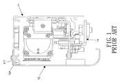
FIG. 1 andFIG.2 illustrate a chassis structure applied on the auto sliding door comprising aframe body 11, acover 12, adrive motor 13 and a plurality ofspreaders 14. Theframe body 11 has areceiving space 111. Thecover 12 could be opening or closing theframe body 11. Oneend part 121 of thecover 12 locating in thereceiving space 111 is able to move in thereceiving space 111 while doing opening and closing process. Thedrive motor 13 locates in theframe body 11 and thespreaders 14 could install on theframe body 11 as slide moving components. The plurality of spreaders is used to fix the door slides. - In general, the aforementioned chassis structure is installed on the ceiling or the height on the wall. Thus, when the device inside the chassis structure is damaged or broken, technicians have to work at height position and then to lift the cover for maintaining the device. However, there is no locking mechanism in the inner wall between the
receiving space 111 and theend part 121 of thecover 12 to fix thecover 12 at certain location while thecover 12 is opening. Due to the gravity, thecover 12 would fall down to close theframe body 11 and would bring inconvenience and hurt to the technicians as well as damage to the device. - In accordance with aspects of the present invention, while the cover of the chassis structure with locking function is opening, the locking mechanism could fix the cover at certain location to prevent the cover falling down to close the frame body.
- In order to achieve the aforementioned objectives, the current invention provides a chassis structure with cover locking function applied on the auto sliding door which comprises a frame body and a cover.
- The frame body having a receiving space which has an engaging member on at least one wall of it and a fulcrum member on a wall of it. The cover combines to the frame body for opening and closing the chassis structure. An end part of the cover forms a hooking member and pivoting member corresponding to the receiving space of the frame body.
- While the cover is opening to a certain position, the hooking member of the cover would go into the receiving space of the frame body and the aforementioned engaging member would fix the hooking member of the cover for locking the cover at the certain position. When the cover is at the closing position, the hooking member of the cover is away from the engaging member of the frame body and the pivoting member of the cover rests on the fulcrum member.
- The current invention has following benefits. The cover could be fixed at a certain opening position since the hooking member of the cover catches the engaging member on the wall of the receiving space. Due to the hooking member of the cover hooking the engaging member on the wall of the receiving space, the cover would not fall down to close the frame body and would not bring inconvenience and hurt to the technicians as well as damage to the device.
- The foregoing aspects and many of the attendant advantages of this invention will become more readily appreciated as the same becomes better understood by reference to the following detailed description, when taken in conjunction with the accompany drawings, wherein like reference numerals refer to like parts throughout the various views unless otherwise specified.
-
Fig.1 illustrates the plan diagram of the chassis structure of conventional auto sliding door which shows the cover is in closing status. -
Fig.2 illustrates the plan diagram of the chassis structure of conventional auto sliding door which shows the cover is in opening status. -
Fig.3 illustrates the pictorial drawing of the current invention. -
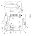
Fig.4 illustrates the plan diagram of the current invention which shows the cover in closing status. -
Fig.5 illustrates the plan diagram of the current invention which shows the process of cover gradually opening. -
Fig.6 illustrates the plan diagram of the current invention which shows the process of cover gradually opening. -
Fig.7 illustrates the plan diagram which shows the cover shifts at the certain position. -
Fig.8 illustrates a better embodiment which shows the pivoting member working with the engaging member. -
Fig.9 illustrates the pictorial drawing of receiving space design of another better embodiment of current invention. -
Fig.10 illustrates the plan combination diagram ofFig.9 . -
Fig.11 illustrates the pictorial drawing of the receiving space created by the support frame and frame body. -
Fig.12 illustrates the plan combination diagram ofFig.11 . -
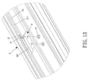
Fig.13 illustrates the pictorial exploded drawing of the piece frame screwed on the frame body. -
Fig.14 illustrates the plan combination diagram ofFig. 13 . - As shown in
Fig.3 andFig.4 , the current invention provides a chassis structure with cover locking function which is applied on the auto sliding door comprising aframe body 2, acover 3, asupport frame 4 andattraction button 5. - The
frame body 2,cover 3 andsupport frame 3 are formed by shaped aluminum extraction. Theframe body 2 has areceiving space 6 on an end part. In a better embodiment of current invention, the quantity of the receiving space could be one or multiple. Theengaging member 61 forms on the at least one wall of thereceiving space 6. Afulcrum member 62 is installed on the wall of thereceiving space 6. In a better embodiment, as shown in the Figure, theengaging member 61 is aprotrusion 611 extending from the wall of thereceiving space 6. Besides, the inner wall of theframe body 2 could stretch out to be afixing rack 21. Thefixing rack 21 would form as asetting groove 211. Furthermore, theframe body 2 has adrive motor 7 andspreaders 8 installed inward. Thespreaders 8 could slide on theframe body 2. Thedrive motor 7 is used to drive thespreaders 8 slide on theframe body 2. Themotor 7 and thespreaders 8 are connected with a belt and thespreaders 8 assemble to the door slide which is not shown in the figure. - An end part of the
cover 3 forms a hookingmember 301 and a pivotingmember 302. Thecover 3 has abase portion 31 and the extension part of the base portion is bended to form abent portion 32. The aforementioned hookingmember 301 and the pivotingmember 302 are formed by the extension of the end part of thebase portion 31. In addition, the inner wall of thecover 3 forms at least oneslot 33. Theslot 33 could be formed by the extension of the inner wall of thebase portion 31 andside wall film 32. - The
support frame 4 could be a strip-like shape and length of thesupport frame 4 is approximate or equal to length of theframe body 2. The number of thesupport frame 4 could also be two or three above. The current invention takes three as the example. The support frame could form thesetting slot 41. - The quantity of the
attraction button 5 corresponds to the quantity of theaforementioned support frame 4. Eachattraction button 5 has an attractingcomponent 51 and an attractedcomponent 52. The number of the attractingcomponent 51 and the attractedcomponent 52 are installed according to the requirement. - The attracting
component 51 could be a magnet which has magnetism and the attractedcomponent 52 could be a piece of iron which has permeability. Thus, the attractingcomponent 51 is able to attract the attractedcomponent 52. Moreover, the attractedcomponent 52 could also be a magnetic so that the two components could attract each other while the two of the magnetic pole are opposite. The attractingcomponent 51 and the attractedcomponent 52 of theattraction button 5 are installed at corresponding position on thesupport frame 4 and thecover 3, in which the attractingcomponent 51 could be installed on thesupport frame 4, and the attractedcomponent 52 is installed on inside of thecover 3. The positions of the two corresponding components could be switched each other. Moreover, the attractingcomponent 51 or the attractedcomponent 52 could be installed in theslot 33. The attractingcomponent 51 or the attractedcomponent 52 could be correspondingly installed in thesetting slot 41. - In a better embodiment, the
support frame 4 is fixed on theframe body 2. Please refer toFig.11 andFig.12 , the screw S locates in the settinggroove 211 of the fixingtrack 21 and partially goes through the fixingtrack 21 as well as goes through the combination endpart 42 assembled with thesupport frame 4 andframe body 2. Then, the nut H screws with the prominent part P of the screw S together to support the combination endpart 42. Therefore, the combination of the fixingtrack 21 and the combination endpart 42 of thesupport frame 4 could be created and further secure thesupport frame 4 on theframe body 2. - The
cover 3 would be able to combine to theframe body 2 due to opening and closing. The end part of thecover 3 having hookingmember 301 and pivotingmember 302 is corresponding to the receivingspace 6 on theframe body 2. The end part is able to go into and get out from the receivingspace 6 while taking opening and closing actions. As shown inFig.4 , while thecover 3 is at the closing position, the hookingmember 301 is away from the engagingmember 61 of the receivingspace 6 of theframe body 2 and the pivotingmember 302 catches thefulcrum member 62 to prevent thecover 3 from loosing out theframe body 2. Meanwhile, the attractingcomponent 51 of theattraction 5 would be able to attract the attractedcomponent 52 for locking thecover 3 at the closing position. - As shown in the
Fig.5 to Fig.7 , while thecover 3 is gradually lifted, the attractingcomponent 51 and attractedcomponent 52 would be gradually separated. The hookingmember 301 would also gradually go into the receivingspace 6 at the same time. When thecover 3 reaches certain position, the engagingmember 61 in the receivingspace 6 would stock the hookingmember 301 of thecover 3 for locking thecover 3 at certain position. In current embodiment, sinceprotrusion 611 of the engagingmember 61 stocks the hookingmember 301 and uses the touching point of thefulcrum member 62 and thebase portion 31 of thecover 3 as a fulcrum so that thecover 3 could be locked at certain position. - In addition, in current embodiment, the receiving
space 6 on theframe body 2 is formed by an end part of the frame body and part of theend part 42 of thesupport frame 4. The aforementioned engagingmember 61 is formed by the extension of the frame body. Thefulcrum member 62 locates on the wall of the receivingspace 6 formed from thesupport frame 4 which has advantages of saving the cost of theframe body 2. - As shown in
Fig.8 , in another better embodiment, while thecover 3 reaches certain position, the engaging member 61' in the receivingspace 6, a projection 611' of the wall of the receivingspace 6, would stock the hookingmember 301 of thecover 3 for locking thecover 3 at certain position. In current embodiment, since projection 611' of the engaging member 61' stocks the hookingmember 301 and uses the contacting point of thefulcrum member 62 and thebase portion 31 of thecover 3 as a fulcrum, so that thecover 3 could be locked at certain position. - The design of the
aforementioned receiving space 6, in another better embodiment as shown in theFig.9 andFig.10 , the receiving space 6' is formed by the extension of an end part of theframe body 2. - Please refer to
Fig.3 ,Fig.13 andFig.14 , the current invention could further includes multiple supportingpiece 9. The number of the supporting pieces is according the requirement such as 2, 3 or 4 more. The supportingpiece 9 combines with theframe body 2 and create the receivingspace 6 with theframe body 2. The supporting piece is physically screwed by screw S' into thegroove 211 of the fixingtrack 21 and partially goes out the fixingtrack 21. Then, the nut H' screws with the prominent part P' of the screw S' together to stock an end part of the supportingpiece 9. Therefore, one end of the supportingpiece 9 could be fixed on theframe body 2 and the other end of the supportingpiece 9 would create the receivingspace 6 with theframe body 2. - According to the aforementioned description, in the current invention, the cover could be fixed at a certain opening position since the hooking member of the cover catches the engaging member on the wall of the receiving space. Due to the hooking member of the cover hooking the engaging member on the wall of the receiving space, the cover would not fall down to close the frame body and would not bring inconvenience and hurt to the technicians as well as damage to the device.
- Furthermore, in the conventional chassis structure, the cover would stably fix on the frame body while screw screwing through the cover to fix on the frame body. However, this will not only bring inconvenience to technicians but also has relative unattractive appearance of the chassis structure. Therefore, the current invention with attraction device which provides an attracting component and an attracted component so that the two components could attract each other.
- Some modifications of these examples, as well as other possibilities will, on reading or having read this description, or having comprehended these examples, will occur to those skilled in the art. Such modifications and variations are comprehended within this invention as described here and claimed below. The description above illustrates only a relative few specific embodiments and examples of the invention. The invention, indeed, does include various modifications and variations made to the structures and operations described herein, which still fall within the scope of the invention as defined in the following claims.
Claims (11)
- A chassis structure with cover locking function applied on the auto sliding door, comprising:a frame body having an engaging member arranged and a fulcrum member, wherein the inner surface between the engaging member and the fulcrum member defining a receiving space;a cover pivotally coupled to the frame body selectable between an open and a closed configuration, wherein one side of the cover includes a pivoting member pivotable about the fulcrum member of the frame body and a hooking member engage-able with the engaging member of the frame body;wherein while in the open configuration, the hooking member of the cover extends into the receiving space of the frame body and the hooking member engages the engaging member of the frame body,wherein while in the closed configuration, the hooking member of the cover disengages the engaging member of the frame body and the pivoting member hangs on the fulcrum member.
- The chassis structure with cover locking function of claim 1, wherein comprises a support frame and an attraction device, the support frame installed on the frame body, the attraction device having attracting component and attracted component, the attracting component and attracted component separately locate at corresponding position on the support frame or the cover, wherein the attracting component and attracted component of the attraction device are away from each other while the cover is at opening position, the attracting component of the attraction device attracts the corresponding attracted component to fix the cover at the closing position.
- The chassis structure with cover locking function of claim 1 or claim 2, wherein the engaging member is a projection of the wall of the receiving space to stock the pivoting member of the cover while the cover is opening at a certain position.
- The chassis structure with cover locking function of claim 1 or claim 2, wherein the engaging member is a protrusion of the wall of the receiving space to stock the pivoting member of the cover while the cover is opening at a certain position.
- The chassis structure with cover locking function of claim 2, wherein the receiving space locating at the frame body is formed by an end part and part of the assembling end part of the support frame and the frame body.
- The chassis structure with cover locking function of claim 5, wherein the frame body has multiple supporting pieces, the supporting pieces and the frame body create the aforementioned receiving space together.
- The chassis structure with cover locking function of claim 6, wherein the fixing rack protrudes from the inner wall of the frame body, the fixing rack and an end part of the supporting piece combined together with screw and nut screwing each other.
- The chassis structure with cover locking function of claim 2, the inner wall of the cover forms a slot, the support frame forms a setting slot, the attracting component or the attracted component could be selectively installed in the slot of the cover, and the attracting component or the attracted component could be correspondingly installed in the setting slot of the support frame.
- The chassis structure with cover locking function of claim 1 or claim 2, wherein a drive motor and a spreader are in the frame body, the spreader could slide move on the frame body and the drive motor drive the spreader for slide moving on the frame body.
- The chassis structure with cover locking function of claim 1 or claim 2, wherein the receiving space is formed by one extension end part of the frame body.
- The chassis structure with cover locking function of claim 2, wherein the fixing rack protrudes from the inner wall of the frame body, the assembling end part of the support frame and the frame body combines to the fixing rack with screw and nut screwing each other.
Priority Applications (1)
| Application Number | Priority Date | Filing Date | Title |
|---|---|---|---|
| EP10191309A EP2453087A1 (en) | 2010-11-16 | 2010-11-16 | Chassis structure having cover retaining mechanism |
Applications Claiming Priority (1)
| Application Number | Priority Date | Filing Date | Title |
|---|---|---|---|
| EP10191309A EP2453087A1 (en) | 2010-11-16 | 2010-11-16 | Chassis structure having cover retaining mechanism |
Publications (1)
| Publication Number | Publication Date |
|---|---|
| EP2453087A1 true EP2453087A1 (en) | 2012-05-16 |
Family
ID=43858409
Family Applications (1)
| Application Number | Title | Priority Date | Filing Date |
|---|---|---|---|
| EP10191309A Withdrawn EP2453087A1 (en) | 2010-11-16 | 2010-11-16 | Chassis structure having cover retaining mechanism |
Country Status (1)
| Country | Link |
|---|---|
| EP (1) | EP2453087A1 (en) |
Cited By (6)
| Publication number | Priority date | Publication date | Assignee | Title |
|---|---|---|---|---|
| EP3020903A1 (en) * | 2014-11-14 | 2016-05-18 | DORMA Deutschland GmbH | Cover fastener |
| JP2016138365A (en) * | 2015-01-26 | 2016-08-04 | 積水ハウス株式会社 | Wall structure |
| JP2016138366A (en) * | 2015-01-26 | 2016-08-04 | 積水ハウス株式会社 | Wall structure |
| WO2019201606A1 (en) * | 2018-04-17 | 2019-10-24 | Grass Gmbh | Device for moving a furniture part and piece of furniture |
| IT202300024654A1 (en) * | 2023-11-21 | 2025-05-21 | Face S R L | PROTECTIVE CASING FOR AT LEAST PART OF THE AUTOMATION OF AN AUTOMATIC DOOR. |
| WO2025233123A1 (en) * | 2024-05-06 | 2025-11-13 | Assa Abloy Entrance Systems Ab | A cover for a horizontal drive compartment for a sliding door with a top side and a method of opening the cover |
Citations (2)
| Publication number | Priority date | Publication date | Assignee | Title |
|---|---|---|---|---|
| US20050150168A1 (en) * | 2004-01-09 | 2005-07-14 | Overhead Door Corporation | Sliding door |
| FR2936005A1 (en) * | 2008-09-16 | 2010-03-19 | Fermod | Sliding door system for opening and closing clean room, has fixation units comprising openings fixed to rail such that longitudinal axis of rail is slantingly extended along partial level plane parallel to ground |
-
2010
- 2010-11-16 EP EP10191309A patent/EP2453087A1/en not_active Withdrawn
Patent Citations (2)
| Publication number | Priority date | Publication date | Assignee | Title |
|---|---|---|---|---|
| US20050150168A1 (en) * | 2004-01-09 | 2005-07-14 | Overhead Door Corporation | Sliding door |
| FR2936005A1 (en) * | 2008-09-16 | 2010-03-19 | Fermod | Sliding door system for opening and closing clean room, has fixation units comprising openings fixed to rail such that longitudinal axis of rail is slantingly extended along partial level plane parallel to ground |
Cited By (8)
| Publication number | Priority date | Publication date | Assignee | Title |
|---|---|---|---|---|
| EP3020903A1 (en) * | 2014-11-14 | 2016-05-18 | DORMA Deutschland GmbH | Cover fastener |
| EP3020903B1 (en) | 2014-11-14 | 2021-11-10 | dormakaba Deutschland GmbH | Cover fastener |
| JP2016138365A (en) * | 2015-01-26 | 2016-08-04 | 積水ハウス株式会社 | Wall structure |
| JP2016138366A (en) * | 2015-01-26 | 2016-08-04 | 積水ハウス株式会社 | Wall structure |
| WO2019201606A1 (en) * | 2018-04-17 | 2019-10-24 | Grass Gmbh | Device for moving a furniture part and piece of furniture |
| IT202300024654A1 (en) * | 2023-11-21 | 2025-05-21 | Face S R L | PROTECTIVE CASING FOR AT LEAST PART OF THE AUTOMATION OF AN AUTOMATIC DOOR. |
| EP4560101A1 (en) * | 2023-11-21 | 2025-05-28 | Face S.r.l. | Protection casing for at least part of the automation of an automatic door |
| WO2025233123A1 (en) * | 2024-05-06 | 2025-11-13 | Assa Abloy Entrance Systems Ab | A cover for a horizontal drive compartment for a sliding door with a top side and a method of opening the cover |
Similar Documents
| Publication | Publication Date | Title |
|---|---|---|
| EP2453087A1 (en) | Chassis structure having cover retaining mechanism | |
| US20120325999A1 (en) | Multi-orientation support | |
| CN111911762A (en) | Load support and have cloud platform of this load support | |
| US20070046159A1 (en) | Motion control bracket with integrated motion control device | |
| US20150185790A1 (en) | Expansion card chassis assembly | |
| US10820734B1 (en) | Positioning structure of curtain rod | |
| US20180242736A1 (en) | Bracket for drawer slide | |
| KR20170002548A (en) | Screwless three piece vertical electronic device | |
| US10349541B2 (en) | Device for the tool-free mounting of modules on a top-hat rail and for the destruction-free, tool-free unmounting of the same | |
| TWI417032B (en) | Fixing mechanism for fixing components | |
| US20060279184A1 (en) | Computer enclosure with connecting device | |
| US8444233B2 (en) | Electronic device with a resilient bracket | |
| US20150349442A1 (en) | Electrical connector assembly with locking member | |
| US20110199761A1 (en) | Light fixture | |
| US8496304B2 (en) | Electronic device enclosure | |
| JP6911781B2 (en) | Shelf board supports and shelves | |
| JP2016122514A (en) | Light source unit and lighting apparatus | |
| US8247691B2 (en) | Connecting member | |
| TWI478654B (en) | Mounting apparatus for sliding rail | |
| CN106660489B (en) | console assembly | |
| US8833759B2 (en) | Printer with re-positionable paper output tray | |
| CN107956983A (en) | Bracket device | |
| US9247808B1 (en) | Hingable support shelf | |
| US10064306B2 (en) | Bracket and equipment rack | |
| JP2011006921A (en) | Mounting structure of entrance panel |
Legal Events
| Date | Code | Title | Description |
|---|---|---|---|
| PUAI | Public reference made under article 153(3) epc to a published international application that has entered the european phase |
Free format text: ORIGINAL CODE: 0009012 |
|
| AK | Designated contracting states |
Kind code of ref document: A1 Designated state(s): AL AT BE BG CH CY CZ DE DK EE ES FI FR GB GR HR HU IE IS IT LI LT LU LV MC MK MT NL NO PL PT RO RS SE SI SK SM TR |
|
| AX | Request for extension of the european patent |
Extension state: BA ME |
|
| STAA | Information on the status of an ep patent application or granted ep patent |
Free format text: STATUS: THE APPLICATION IS DEEMED TO BE WITHDRAWN |
|
| 18D | Application deemed to be withdrawn |
Effective date: 20121117 |