EP2455540A1 - A steamer head for a garment steamer - Google Patents
A steamer head for a garment steamer Download PDFInfo
- Publication number
- EP2455540A1 EP2455540A1 EP10191618A EP10191618A EP2455540A1 EP 2455540 A1 EP2455540 A1 EP 2455540A1 EP 10191618 A EP10191618 A EP 10191618A EP 10191618 A EP10191618 A EP 10191618A EP 2455540 A1 EP2455540 A1 EP 2455540A1
- Authority
- EP
- European Patent Office
- Prior art keywords
- steam
- fabric
- garment
- steamer
- air
- Prior art date
- Legal status (The legal status is an assumption and is not a legal conclusion. Google has not performed a legal analysis and makes no representation as to the accuracy of the status listed.)
- Withdrawn
Links
Images



Classifications
-
- D—TEXTILES; PAPER
- D06—TREATMENT OF TEXTILES OR THE LIKE; LAUNDERING; FLEXIBLE MATERIALS NOT OTHERWISE PROVIDED FOR
- D06F—LAUNDERING, DRYING, IRONING, PRESSING OR FOLDING TEXTILE ARTICLES
- D06F73/00—Apparatus for smoothing or removing creases from garments or other textile articles by formers, cores, stretchers, or internal frames, with the application of heat or steam
-
- D—TEXTILES; PAPER
- D06—TREATMENT OF TEXTILES OR THE LIKE; LAUNDERING; FLEXIBLE MATERIALS NOT OTHERWISE PROVIDED FOR
- D06F—LAUNDERING, DRYING, IRONING, PRESSING OR FOLDING TEXTILE ARTICLES
- D06F87/00—Apparatus for moistening or otherwise conditioning the article to be ironed or pressed
Definitions
- the present invention relates to a steamer head for a garment steamer. Furthermore, the present invention also relates to a garment steamer comprising a steamer head and a method of removing creases from a garment using a garment steamer.
- Apparatus for removing creases from the fabric of a garment are commonly known.
- Such apparatus generally comprise an ironing board with an upper surface on which a garment is placed, and an iron with a heated sole plate which is pressed against the garment on the upper surface of the ironing board.
- the use of heat generated by the heated sole plate together with pressure applied by the iron removes creases in the fabric.
- irons are also known to include steam generating means and a plurality of steam holes formed in the heated sole plate through which steam is expelled against the fabric of a garment. Moisture from the steam is used to relax the fabric fibres, while heat from the heated plate raises the fabric material to its glass transition temperature and subsequently dries it to retain its flatness. Therefore, a combined use of heat, moisture and pressure is applied to the fabric to remove the creases formed therein.
- an iron which comprises a heated sole plate with a plurality of steam outlet holes formed in a circular arrangement in the sole plate.
- a plurality of air vent holes are formed in a circular arrangement around the plurality of steam outlet holes, and a vacuum pump means is formed in the iron to suck air through the air vent holes.
- known irons also require a heat control to regulate the temperature of the heated sole plate to account for different types of fabric. Dependent on the type of fabric the iron will either not remove creases if the heat control is set too low, or bum the fabric of the garment if the heat control is set to be too high.
- known irons also rely on the pressure applied by the heated sole plate against an ironing board, to remove creases. Furthermore, as irons require a heated sole plate to remove creases from a fabric, the heated sole plate can cause scorching and/or burning of the fabric if the heated sole plate is left in one position on the fabric.
- Garment steamers are known for steaming garments to remove creases from a fabric material of a garment through the use of heat and moisture.
- a garment steamer generally comprises a steam generating unit and a steamer head connected to the steam generating unit by a steam hose through which steam is conveyed to the steamer head.
- the steamer head is provided with a steam outlet to discharge steam onto the fabric being treated.
- the garment is hung on a hanger during treatment by the steamer and the user stretches the garment with one hand while the steamer head is manipulated over the garment with the other hand.
- conventional garment steamers have the problem that the flow of steam from the steamer head urges the garment away from the steamer head when the steamer head is positioned against the garment.
- a steamer head for a garment steamer comprising a main body with a front end, a steam outlet and an air inlet formed in the front end, and air suction means for drawing air through the air inlet so that a fabric of a garment disposed proximate the front end is drawn against the front end by the air suction means and steam is applied to the fabric of a garment through the steam outlet.
- the front end of the main body comprises first and second surfaces, the steam outlet being formed in the first surface and the air inlet being formed in the second surface, so that the fabric is drawn against the second surface and steam is applied to the fabric at the first surface.
- the second surface may extend from an edge of the first surface.
- the first and second surfaces together form a convex surface.
- the steamer head further comprises a handle configured to orientate the front end of the main body so that the fabric of a garment is drawn against the air inlet prior to passing proximate to the steam outlet when the front end of the main body is drawn along the fabric of a garment.
- the handle may extend from an opposing end of the main body to the front end, and the handle extends at an angle to the first surface of the front end.
- the steamer head further comprises an air passageway formed in the main body which extends between the air inlet and an air outlet, the air suction means being disposed in the air passageway.
- the steamer head further comprises a steam inlet through which steam is supplied to the main body and a steam passageway through which steam flows from the steam inlet to the steam outlet.
- the steamer head comprises a water supply inlet through which water is supplied to the main body and a heating means configured to form steam from water introduced through the water supply inlet.
- the steam outlet comprises an array of steam holes.
- the air inlet comprises an array of air holes.
- the steamer head may further comprise a filter disposed at the air inlet to prevent the ingress of loose fibres from a fabric of a garment into the air suction means.
- a garment steamer comprising a steamer head.
- the garment steamer may further comprise a steam generation unit, wherein the steam inlet of the steamer head is connected to the steam generation unit by a flexible pipe.
- a method of removing creases from a fabric of a garment using a steamer head of a garment steamer comprising a front end with a steam outlet and an air inlet, and an air suction means for drawing air through the air inlet, the method comprising the steps of sucking the fabric against the front end and moving the steamer head along the fabric so that fabric drawn against the air inlet at the front end is subsequently positioned against the steam outlet so that steam is imparted on said fabric.
- a steamer head 1 for a garment steamer is shown.
- the steamer head 1 forms a nozzle which comprises a main body 2 with a handle 3 extending there from.
- a flexible hose 4 extends from the handle 3 at a distal end 5 to the main body 2.
- the flexible hose 4 extends between the steamer head 1 and a steam generation unit, acting as a steam generating means, so that steam generated in the steam generation unit flows along the flexible hose 4 and is provided to the steamer head 1 along the flexible hose 4, as will be explained in detail hereinafter.
- the main body 2 and the handle 3 are integrally formed and comprise a housing 7.
- the main body 2 of the steamer head 1 has a front end 8 and a rear end 9.
- the handle 3 extends from the rear end 9 of the main body 2, and the front end 8 of the main body 2 has a first surface 10 and a second surface 12.
- the housing 7 is formed from a heat resistant moulded plastic.
- the first surface 10 is disposed at an upper end of the front end 8, and has a planar face 13 with a peripheral edge 14 extending there around.
- a plurality of steam holes 15 are formed through the first surface 10 to act as a steam outlet 11.
- the steam holes 15 communicate the planar face 13 with a steam channel 21 formed in the housing 7.
- the steam channel 21 extends between the steam outlet 11 at the front end 8 of the housing 7 and a steam inlet 16 at the distal end 5 of the handle 3.
- the flexible hose 4 is releasably mounted to the steam inlet 16 to provide steam to the steamer head 1, and the steam channel 21 extending between the steam inlet 16 and the steam outlet 11 defines a steam passageway along which steam flows.
- Each steam hole 15 comprises an elongate recess 17 with a base 18 and an aperture 19 formed in the base 18 which extends to the steam channel 21. Therefore, the steam holes 15 communicate the steam channel 21 with the first surface 10 of the housing 7.
- an array of steam holes 15 form the steam outlet 11 in the present embodiment, it will be appreciated that the steam outlet may be a single outlet.
- the second surface 12 is disposed at a lower end of the front end 8 and extends from a lower part of the first surface 10.
- the second surface 12 has a planar face 20. Side edges 22 of the second surface 12 converge from an upper edge 23 of the second surface to a lower edge 24.
- the planar face 20 of the second surface 12 extends parallel to, or is angled slightly away from, the planar face 13 of the first surface 10.
- the second surface 12 is angled away from the first surface 10, it will be appreciated that the first and second surfaces 10, 12 may together form a planar surface. Alternatively, the first and second surfaces 10, 12 may together form a convex surface extending from an upper edge of the first surface to a lower edge 24 of the second surface 12. Furthermore, it will be appreciated that the first and second surfaces 10, 12 may have a convex cross-section between their side edges.
- An advantage of the above arrangements is to aid the drawing of fabric of a garment across the surface of the first and second surfaces 10, 12. For example, the fabric of a garment may snag on the steamer head if a concave surface is provided.
- An air inlet 25 is formed through the planar face 20 of the second surface 12 and extends substantially across the planar face 20 between the side edges 22, and the upper and lower edges 23, 24.
- the air inlet 25 has a grill 27 extending across its opening which forms a number of apertures 26.
- the air inlet 25 communicates the second surface 12 of the main body 2 with an air channel 28 formed in the main body 2.
- the air channel 28 is formed in the main body 2 below the steam channel 21, and extends from the air inlet 25 at the front end 8 of the main body 2 to an air outlet 29 formed at the rear end 9 of the main body 2.
- the air outlet 29 comprises an outlet grill 30 formed in the rear end 9 of the main body 2, below the handle 3.
- the air channel 28 forms an air passageway through which air sucked in through the air inlet 25 flows to and out of the air outlet 29, as will become apparent hereinafter.
- An axial fan 32 acting as an air suction means, is disposed in the air channel 28 to draw air through the air inlet 25 into the air channel 28 and exhaust it through the air outlet 29. Therefore, a suction effect is generated at the air inlet 25 to cause a low pressure at the second surface 12.
- the fan 32 is driven by an electric motor (not shown) and powered by a battery (not shown) disposed in the housing 7, or by mains power means connected by an electric cable (not shown) which extends along the flexible hose 4.
- the air suction means is an axial fan in the present embodiment, it will be appreciated that alternative air suction means may be used to draw air in through the air inlet 25, for example, a centrifugal fan.
- a deflector plate 33 is disposed between the air outlet 29 and the handle 3 to deflect air exhausted out of the air outlet 29 away from a user's hand when they are holding the handle 3.
- the handle 3 extends at an angle downwardly from the main body 2, such that it extends at an acute angle to the planar face 13 of the first surface 10.
- Operation buttons are mounted to the handle 3 or main body 2 to actuate the steam generating means and the air suction means so as to cause the flow of steam out of the steam outlet 11 and the flow of air into the air inlet 25.
- the flow of steam through the steam passageway and the flow of air through the air passageway may be operated independently or concurrently.
- a filter (not shown) is fitted over the air inlet to prevent the ingress of loose fibres from the fabric of a garment or other detritus from being drawn into the fan 32.
- a user holds the steamer head 1 by the handle 3 with the front end 8 of the main body 2 extending away from the user's body.
- the arrangement of the handle 3 and main body 2, with the handle 3 extending downwardly at an angle away from the main body 2 means that in a correct holding position the first surface 10 at the front end 8 of the main body 2 is positioned above the second surface 12 at the front end 8, such that the steam outlet 11 is disposed above the air inlet 25.
- the steamer head 1 is fluidly connected to the steam generation unit by the flexible hose 4.
- the user hangs the garment from a garment hanger, such that the fabric of the garment hangs from the garment hanger in a vertical orientation and locates the steamer head 1 against the fabric.
- the garment may be arranged and supported in other orientations.
- the user actuates the steam generating means and the vacuum pump means by operating the operation buttons.
- steam generated by the steam generation unit is supplied to the steam inlet 16 at the distal end 5 of the steamer head handle 3 via the flexible hose 4.
- the steam then flows along the steam channel 21 to the steam outlet 11 and flows out of the plurality of steam holes 15 towards the fabric disposed proximate thereto.
- the fan 32 is operated to create a flow of air in the air passageway 28, such that air is sucked in through the air inlet 25, drawn through the air channel 28 and exhausted through the air outlet 29. Therefore, a low pressure is created at the air inlet 25 and the fabric of the garment is drawn against the second surface 12. As the fabric of the garment is drawn towards the air inlet 25, the fabric is held against the first surface 10 at the front end 8 of the main body 2. Steam expressed from the steam outlet 11 is therefore expelled from the steam outlet 11, directly against the fabric and is forced through the fabric or between the fabric and the first surface 10. Furthermore, as the air inlet 25 is formed on a different surface to the steam outlet 11, the steam is not drawn into the air inlet 25 and does not travel along the air passageway 28 to the air outlet 29.
- An advantage of this arrangement is that steam-laden air does not pass through the fan 32 and is not exhausted towards the user.
- air outlet 29 is disposed away from the air inlet 25, and so air is not exhausted back towards the fabric of a garment and does not urge the fabric away from the front end 8 of the steamer head.
- the user then draws the steamer head along the fabric in a downwardly acting motion in the direction of the second surface 12 of the main body front end 8, so that the air inlet 25 is drawn across the fabric prior to the steam outlet 11 being drawn across the fabric.
- the steamer head 1 As the steamer head 1 is drawn in a downwardly acting motion, with a section of the fabric being drawn against the air inlet 25, the fabric is tensioned between a garment hanger on which the garment is hung and the second surface 12 of the main body 2. Therefore, the section of fabric opposing the steam outlet 11 is in tension as steam is applied to it, which enhances the ability of the steamer head to remove creases from the fabric of a garment.
- the steamer head 1 is drawn downwardly so that the fabric is positioned against the air inlet 25 prior to the fabric being positioned against the steam outlet 11, the steam expelled from the steam outlet 11 is not drawn into the air inlet 25 and so steam-laden air is not exhausted towards a user.
- the grill 27 extending across the air inlet 25 acts to prevent a garment drawn onto the second surface 12 from being drawn into the air passageway 28, and also ensures a uniform flow of air at the air inlet 25 and through the air passageway 28.
- An advantage of the above arrangement, wherein the air inlet comprises a single inlet area, as opposed to a plurality of smaller air inlets spaced apart from each other, is that the suction effect created is enhanced, which ensures that the fabric is drawn against the main body of the steamer head and is not urged away by the flow of steam from the steam outlet.
- a further advantage of the above described steamer head is that the steamer head does not require a heated surface against which the fabric lies to remove creases from the fabric, and so there is no requirement for a heated sole plate which may cause scorching or burning of the fabric.
- the air inlet 25 is positioned at a lower end of the front end 8 and the steam outlet 11 is positioned at an upper end of the front end 8, above the air inlet 25, it will be appreciated that another air inlet may also be disposed above the steam outlet. In this arrangement the steam outlet will be disposed between the two air inlets, which will provide additional suction to draw the fabric of a garment against the front end of the steamer head.
- FIG. 4 Another embodiment of the steamer head is shown in Figure 4 .
- This embodiment of the invention is generally the same as the first embodiment described above, and so a detailed description will be omitted herein. Furthermore, components and features corresponding to components and features described in the foregoing embodiments will retain the same reference numerals.
- an air outlet 40 is disposed at the distal end 5 of the handle 3 to the main body 2. Therefore, the air passageway extends from the air inlet 25 formed at the front end 8 of the main body 2 in the housing 7 and extends along the length of the handle 3 to the air outlet 40. Therefore, when a user holds the handle 3 of the steamer head 1, air exhausted from the air outlet 40 is exhausted behind the user's hand.
- the steamer head comprises a water inlet which is fluidly connected to a water supply hose.
- the water inlet communicates with a fluid passageway which extends in the housing of the steamer head, between the water inlet and the steam outlet.
- a heating means in the form of a heating element is disposed in the fluid passageway. As water supplied to the fluid passageway flows along the fluid passageway to the steam outlet the water comes into contact with and is heated by the heating means and turned into steam. Therefore, the steam flows out of the steam outlet.
Landscapes
- Engineering & Computer Science (AREA)
- Textile Engineering (AREA)
- Treatment Of Fiber Materials (AREA)
- Professional, Industrial, Or Sporting Protective Garments (AREA)
Abstract
The present invention relates to a steamer head for a garment steamer. The steamer head comprises a main body (2) with a front end (8), a steam outlet (11) and an air inlet (25) formed in the front end (8), and air suction means (32) for drawing air through the air inlet (25). Therefore, a fabric of a garment disposed proximate the front end (8) is drawn against the front end (8) by the air suction means (32) and steam is applied to the fabric of the garment through the steam outlet (11). The present invention also relates to a garment steamer comprising a steamer head and a method of removing creases from a garment using a garment steamer.
Description
- The present invention relates to a steamer head for a garment steamer. Furthermore, the present invention also relates to a garment steamer comprising a steamer head and a method of removing creases from a garment using a garment steamer.
- Apparatus for removing creases from the fabric of a garment are commonly known. Such apparatus generally comprise an ironing board with an upper surface on which a garment is placed, and an iron with a heated sole plate which is pressed against the garment on the upper surface of the ironing board. The use of heat generated by the heated sole plate together with pressure applied by the iron removes creases in the fabric. To further aid the removal of creases, irons are also known to include steam generating means and a plurality of steam holes formed in the heated sole plate through which steam is expelled against the fabric of a garment. Moisture from the steam is used to relax the fabric fibres, while heat from the heated plate raises the fabric material to its glass transition temperature and subsequently dries it to retain its flatness. Therefore, a combined use of heat, moisture and pressure is applied to the fabric to remove the creases formed therein.
- However, a disadvantage of the above arrangement is that ironing boards are cumbersome to set-up and store, and take up a large amount of working space during use.
- An attempt to deal with the abovementioned problems with conventional irons and ironing boards is known from
US 2004/0084433 A1 . In this document an iron is known which comprises a heated sole plate with a plurality of steam outlet holes formed in a circular arrangement in the sole plate. A plurality of air vent holes are formed in a circular arrangement around the plurality of steam outlet holes, and a vacuum pump means is formed in the iron to suck air through the air vent holes. When the fabric of a garment is positioned against the heated sole plate, the vacuum pump means is operated so that a low pressure is generated at the sole plate and so the fabric is drawn against the heated sole plate. - However a problem with the iron disclosed in this document, and other known irons, is that the heated sole plate, heating means for heating the heated plate and the steam generating means for producing steam are all enclosed in the main body of the iron. Therefore, the main body of the iron is heavy, difficult to manoeuvre and cannot be held by a user for any considerable length of time without resting the iron on an ironing board or an other surface. Additionally, irons must be of a sufficient size to include a water tank and water delivery system. Therefore, the mobility of a known iron is restricted due to the size and weight of the iron. Another problem with the iron in
US 2004/0084433 A1 is that the flow of steam and air through the steam outlet holes urges the fabric of a garment away from the heated sole plate and so reduces the effectiveness of the iron. - Known irons also require a heat control to regulate the temperature of the heated sole plate to account for different types of fabric. Dependent on the type of fabric the iron will either not remove creases if the heat control is set too low, or bum the fabric of the garment if the heat control is set to be too high. In addition, known irons also rely on the pressure applied by the heated sole plate against an ironing board, to remove creases. Furthermore, as irons require a heated sole plate to remove creases from a fabric, the heated sole plate can cause scorching and/or burning of the fabric if the heated sole plate is left in one position on the fabric.
- Garment steamers are known for steaming garments to remove creases from a fabric material of a garment through the use of heat and moisture. Such a garment steamer generally comprises a steam generating unit and a steamer head connected to the steam generating unit by a steam hose through which steam is conveyed to the steamer head. The steamer head is provided with a steam outlet to discharge steam onto the fabric being treated. Typically, the garment is hung on a hanger during treatment by the steamer and the user stretches the garment with one hand while the steamer head is manipulated over the garment with the other hand. However, conventional garment steamers have the problem that the flow of steam from the steamer head urges the garment away from the steamer head when the steamer head is positioned against the garment.
- In an attempt to solve the above problems with conventional steamers, a user needs to hold the garment against the steamer head. However, this requires a two handed operation and the user's hand is positioned in the way of the steamer head and so may be scolded by the steam exhausted from the steamer head. Protective gloves and pads are known for supporting the garment from behind while the steamer head is pressed and moved across the garment to aid the removal of creases and to help prevent injury to a user. A further disadvantage is that it is difficult to manipulate the garment which is hung on the hanger to avoid unintended folds and creases and to keep the garment steady during the treatment.
- Therefore, it is an object of the invention to provide a steamer head for a garment steamer which substantially alleviates or overcomes the problems mentioned above.
- According to the present invention, there is provided a steamer head for a garment steamer comprising a main body with a front end, a steam outlet and an air inlet formed in the front end, and air suction means for drawing air through the air inlet so that a fabric of a garment disposed proximate the front end is drawn against the front end by the air suction means and steam is applied to the fabric of a garment through the steam outlet.
- Preferably, the front end of the main body comprises first and second surfaces, the steam outlet being formed in the first surface and the air inlet being formed in the second surface, so that the fabric is drawn against the second surface and steam is applied to the fabric at the first surface.
- The second surface may extend from an edge of the first surface.
- The first and second surfaces together form a convex surface.
- Conveniently, the steamer head further comprises a handle configured to orientate the front end of the main body so that the fabric of a garment is drawn against the air inlet prior to passing proximate to the steam outlet when the front end of the main body is drawn along the fabric of a garment.
- The handle may extend from an opposing end of the main body to the front end, and the handle extends at an angle to the first surface of the front end.
- Preferably, the steamer head further comprises an air passageway formed in the main body which extends between the air inlet and an air outlet, the air suction means being disposed in the air passageway.
- In one embodiment, the steamer head further comprises a steam inlet through which steam is supplied to the main body and a steam passageway through which steam flows from the steam inlet to the steam outlet.
- In another embodiment, the steamer head comprises a water supply inlet through which water is supplied to the main body and a heating means configured to form steam from water introduced through the water supply inlet.
- Preferably, the steam outlet comprises an array of steam holes.
- Conveniently, the air inlet comprises an array of air holes.
- The steamer head may further comprise a filter disposed at the air inlet to prevent the ingress of loose fibres from a fabric of a garment into the air suction means.
- According to another aspect of the invention, there is provided a garment steamer comprising a steamer head.
- The garment steamer may further comprise a steam generation unit, wherein the steam inlet of the steamer head is connected to the steam generation unit by a flexible pipe.
- According to another aspect of the invention, there is provided a method of removing creases from a fabric of a garment using a steamer head of a garment steamer, the steamer head comprising a front end with a steam outlet and an air inlet, and an air suction means for drawing air through the air inlet, the method comprising the steps of sucking the fabric against the front end and moving the steamer head along the fabric so that fabric drawn against the air inlet at the front end is subsequently positioned against the steam outlet so that steam is imparted on said fabric.
- Preferred embodiments of the invention will now be described, by way of example only, with reference to the accompanying drawings, in which:
-
Figure 1 shows a perspective view of an a steamer head for a garment steamer; -
Figure 2 shows a perspective view from below of the steamer head shown inFigure 1 ; -
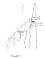
Figure 3 shows a side view of the steamer head shown inFigure 1 , located against a garment; and -
Figure 4 shows a side view of a steamer head according to another embodiment of the invention. - Referring now to
Figures 1 to 3 , a steamer head 1 for a garment steamer is shown. The steamer head 1 forms a nozzle which comprises amain body 2 with ahandle 3 extending there from. Aflexible hose 4 extends from thehandle 3 at adistal end 5 to themain body 2. Theflexible hose 4 extends between the steamer head 1 and a steam generation unit, acting as a steam generating means, so that steam generated in the steam generation unit flows along theflexible hose 4 and is provided to the steamer head 1 along theflexible hose 4, as will be explained in detail hereinafter. - The
main body 2 and thehandle 3 are integrally formed and comprise ahousing 7. Themain body 2 of the steamer head 1 has afront end 8 and arear end 9. Thehandle 3 extends from therear end 9 of themain body 2, and thefront end 8 of themain body 2 has afirst surface 10 and asecond surface 12. In the present embodiment, thehousing 7 is formed from a heat resistant moulded plastic. - The
first surface 10 is disposed at an upper end of thefront end 8, and has aplanar face 13 with aperipheral edge 14 extending there around. A plurality of steam holes 15 are formed through thefirst surface 10 to act as asteam outlet 11. The steam holes 15 communicate theplanar face 13 with asteam channel 21 formed in thehousing 7. Thesteam channel 21 extends between thesteam outlet 11 at thefront end 8 of thehousing 7 and asteam inlet 16 at thedistal end 5 of thehandle 3. - The
flexible hose 4 is releasably mounted to thesteam inlet 16 to provide steam to the steamer head 1, and thesteam channel 21 extending between thesteam inlet 16 and thesteam outlet 11 defines a steam passageway along which steam flows. Eachsteam hole 15 comprises anelongate recess 17 with abase 18 and anaperture 19 formed in the base 18 which extends to thesteam channel 21. Therefore, the steam holes 15 communicate thesteam channel 21 with thefirst surface 10 of thehousing 7. Although an array of steam holes 15 form thesteam outlet 11 in the present embodiment, it will be appreciated that the steam outlet may be a single outlet. - The
second surface 12 is disposed at a lower end of thefront end 8 and extends from a lower part of thefirst surface 10. Thesecond surface 12 has aplanar face 20. Side edges 22 of thesecond surface 12 converge from anupper edge 23 of the second surface to a lower edge 24. Theplanar face 20 of thesecond surface 12 extends parallel to, or is angled slightly away from, theplanar face 13 of thefirst surface 10. An advantage of the above arrangement is that theair inlet 25 is in line with the intended direction of movement of the steamer head. - Although in the present embodiment the
second surface 12 is angled away from thefirst surface 10, it will be appreciated that the first andsecond surfaces second surfaces second surface 12. Furthermore, it will be appreciated that the first andsecond surfaces second surfaces - An
air inlet 25 is formed through theplanar face 20 of thesecond surface 12 and extends substantially across theplanar face 20 between the side edges 22, and the upper andlower edges 23, 24. Theair inlet 25 has agrill 27 extending across its opening which forms a number ofapertures 26. - The
air inlet 25 communicates thesecond surface 12 of themain body 2 with anair channel 28 formed in themain body 2. Theair channel 28 is formed in themain body 2 below thesteam channel 21, and extends from theair inlet 25 at thefront end 8 of themain body 2 to anair outlet 29 formed at therear end 9 of themain body 2. Theair outlet 29 comprises anoutlet grill 30 formed in therear end 9 of themain body 2, below thehandle 3. Theair channel 28 forms an air passageway through which air sucked in through theair inlet 25 flows to and out of theair outlet 29, as will become apparent hereinafter. - An axial fan 32, acting as an air suction means, is disposed in the
air channel 28 to draw air through theair inlet 25 into theair channel 28 and exhaust it through theair outlet 29. Therefore, a suction effect is generated at theair inlet 25 to cause a low pressure at thesecond surface 12. The fan 32 is driven by an electric motor (not shown) and powered by a battery (not shown) disposed in thehousing 7, or by mains power means connected by an electric cable (not shown) which extends along theflexible hose 4. Although the air suction means is an axial fan in the present embodiment, it will be appreciated that alternative air suction means may be used to draw air in through theair inlet 25, for example, a centrifugal fan. - A
deflector plate 33 is disposed between theair outlet 29 and thehandle 3 to deflect air exhausted out of theair outlet 29 away from a user's hand when they are holding thehandle 3. Thehandle 3 extends at an angle downwardly from themain body 2, such that it extends at an acute angle to theplanar face 13 of thefirst surface 10. - Operation buttons (not shown) are mounted to the
handle 3 ormain body 2 to actuate the steam generating means and the air suction means so as to cause the flow of steam out of thesteam outlet 11 and the flow of air into theair inlet 25. The flow of steam through the steam passageway and the flow of air through the air passageway may be operated independently or concurrently. - A filter (not shown) is fitted over the air inlet to prevent the ingress of loose fibres from the fabric of a garment or other detritus from being drawn into the fan 32.
- Operation of the garment steamer according to the above exemplary embodiment will now be described with reference to
Figures 1 to 3 . - A user holds the steamer head 1 by the
handle 3 with thefront end 8 of themain body 2 extending away from the user's body. The arrangement of thehandle 3 andmain body 2, with thehandle 3 extending downwardly at an angle away from themain body 2 means that in a correct holding position thefirst surface 10 at thefront end 8 of themain body 2 is positioned above thesecond surface 12 at thefront end 8, such that thesteam outlet 11 is disposed above theair inlet 25. The steamer head 1 is fluidly connected to the steam generation unit by theflexible hose 4. - To remove creases from the fabric of a garment, the user hangs the garment from a garment hanger, such that the fabric of the garment hangs from the garment hanger in a vertical orientation and locates the steamer head 1 against the fabric. However, it will be appreciated that the garment may be arranged and supported in other orientations.
- Once the steamer head 1 is positioned against the fabric, the user actuates the steam generating means and the vacuum pump means by operating the operation buttons. Upon operation, steam generated by the steam generation unit is supplied to the
steam inlet 16 at thedistal end 5 of the steamer head handle 3 via theflexible hose 4. The steam then flows along thesteam channel 21 to thesteam outlet 11 and flows out of the plurality of steam holes 15 towards the fabric disposed proximate thereto. - The fan 32 is operated to create a flow of air in the
air passageway 28, such that air is sucked in through theair inlet 25, drawn through theair channel 28 and exhausted through theair outlet 29. Therefore, a low pressure is created at theair inlet 25 and the fabric of the garment is drawn against thesecond surface 12. As the fabric of the garment is drawn towards theair inlet 25, the fabric is held against thefirst surface 10 at thefront end 8 of themain body 2. Steam expressed from thesteam outlet 11 is therefore expelled from thesteam outlet 11, directly against the fabric and is forced through the fabric or between the fabric and thefirst surface 10. Furthermore, as theair inlet 25 is formed on a different surface to thesteam outlet 11, the steam is not drawn into theair inlet 25 and does not travel along theair passageway 28 to theair outlet 29. An advantage of this arrangement is that steam-laden air does not pass through the fan 32 and is not exhausted towards the user. In addition, as theair outlet 29 is disposed away from theair inlet 25, and so air is not exhausted back towards the fabric of a garment and does not urge the fabric away from thefront end 8 of the steamer head. - The user then draws the steamer head along the fabric in a downwardly acting motion in the direction of the
second surface 12 of the main bodyfront end 8, so that theair inlet 25 is drawn across the fabric prior to thesteam outlet 11 being drawn across the fabric. - As the steamer head 1 is drawn in a downwardly acting motion, with a section of the fabric being drawn against the
air inlet 25, the fabric is tensioned between a garment hanger on which the garment is hung and thesecond surface 12 of themain body 2. Therefore, the section of fabric opposing thesteam outlet 11 is in tension as steam is applied to it, which enhances the ability of the steamer head to remove creases from the fabric of a garment. In addition, as the steamer head 1 is drawn downwardly so that the fabric is positioned against theair inlet 25 prior to the fabric being positioned against thesteam outlet 11, the steam expelled from thesteam outlet 11 is not drawn into theair inlet 25 and so steam-laden air is not exhausted towards a user. - It will be appreciated that, even if a small portion of steam is sucked into the
air passageway 28, the steam-laden air is directed away from the user by thedeflector plate 33 extending between theair outlet 29 and thehandle 3. - Once the
steam outlet 11 formed in thefirst surface 10 of the main bodyfront end 8 passes over the fabric, the fabric dries due to the heat imparted on it by the steam. Thegrill 27 extending across theair inlet 25 acts to prevent a garment drawn onto thesecond surface 12 from being drawn into theair passageway 28, and also ensures a uniform flow of air at theair inlet 25 and through theair passageway 28. - An advantage of the above arrangement, wherein the air inlet comprises a single inlet area, as opposed to a plurality of smaller air inlets spaced apart from each other, is that the suction effect created is enhanced, which ensures that the fabric is drawn against the main body of the steamer head and is not urged away by the flow of steam from the steam outlet.
- A further advantage of the above described steamer head is that the steamer head does not require a heated surface against which the fabric lies to remove creases from the fabric, and so there is no requirement for a heated sole plate which may cause scorching or burning of the fabric.
- Although in the above arrangements the
air inlet 25 is positioned at a lower end of thefront end 8 and thesteam outlet 11 is positioned at an upper end of thefront end 8, above theair inlet 25, it will be appreciated that another air inlet may also be disposed above the steam outlet. In this arrangement the steam outlet will be disposed between the two air inlets, which will provide additional suction to draw the fabric of a garment against the front end of the steamer head. - Another embodiment of the steamer head is shown in
Figure 4 . This embodiment of the invention is generally the same as the first embodiment described above, and so a detailed description will be omitted herein. Furthermore, components and features corresponding to components and features described in the foregoing embodiments will retain the same reference numerals. However, in this embodiment anair outlet 40 is disposed at thedistal end 5 of thehandle 3 to themain body 2. Therefore, the air passageway extends from theair inlet 25 formed at thefront end 8 of themain body 2 in thehousing 7 and extends along the length of thehandle 3 to theair outlet 40. Therefore, when a user holds thehandle 3 of the steamer head 1, air exhausted from theair outlet 40 is exhausted behind the user's hand. - Although in the above described embodiments of a steamer head for a garment steamer steam is provided to the steamer head through a steam inlet, and the steam is generated in the steam generation unit, it will be appreciated that steam may be provided to the steam outlet in an alternative manner. In a further embodiment of a steamer head for a garment steamer, the steamer head comprises a water inlet which is fluidly connected to a water supply hose. The water inlet communicates with a fluid passageway which extends in the housing of the steamer head, between the water inlet and the steam outlet. A heating means in the form of a heating element is disposed in the fluid passageway. As water supplied to the fluid passageway flows along the fluid passageway to the steam outlet the water comes into contact with and is heated by the heating means and turned into steam. Therefore, the steam flows out of the steam outlet.
- Although claims have been formulated in this application to particular combinations of features, it should be understood that the scope of the disclosure of the present invention also includes any novel features or any novel combinations of features disclosed herein either explicitly or implicitly or any generalization thereof, whether or not it relates to the same invention as presently claims in any claim and whether or not it mitigates any or all of the same technical problems as does the parent invention. The applicants hereby give notice that new claims may be formulated to such features and/or combinations of features during the prosecution of the present application or of any further application derived there from.
Claims (15)
- A steamer head for a garment steamer comprising a main body (2) with a front end (8), a steam outlet (11) and an air inlet (25) formed in the front end (8), and air suction means (32) for drawing air through the air inlet (25) so that a fabric of a garment disposed proximate the front end (8) is drawn against the front end (8) by the air suction means (32) and steam is applied to the fabric of a garment through the steam outlet (11).
- A steamer head according to claim 1, wherein the front end (8) of the main body (2) comprises first and second surfaces (10, 12), the steam outlet (11) being formed in the first surface (10) and the air inlet (25) being formed in the second surface (12), so that the fabric is drawn against the second surface (12) and steam is applied to the fabric at the first surface (10).
- A steamer head according to claim 2, wherein the second surface (12) extends from an edge of the first surface (10).
- A steamer head according to claim 2 or claim 3, wherein the first and second surfaces (10, 12) together form a convex surface.
- A steamer head according to any of claims 2 to 4, further comprising a handle (3) configured to orientate the front end (8) of the main body (2) so that the fabric of a garment is drawn against the air inlet (25) prior to passing proximate to the steam outlet (11) when the front end (8) of the main body (2) is drawn along the fabric of a garment.
- A steamer head according to claim 5, wherein the handle (3) extends from an opposing end (9) of the main body (2) to the front end (8), and the handle (3) extends at an angle to the first surface (10) of the front end (8).
- A steamer head according to any preceding claim, further comprising an air passageway (28) formed in the main body (2) which extends between the air inlet (25) and an air outlet (29), the air suction means (32) being disposed in the air passageway (28).
- A steamer head according to any preceding claim, further comprising a steam inlet (16) through which steam is supplied to the main body (2) and a steam passageway (21) through which steam flows from the steam inlet (16) to the steam outlet (11).
- A steamer head according to any of claims 1 to 8, further comprising a water supply inlet through which water is supplied to the main body (2) and a heating means configured to form steam from water introduced through the water supply inlet.
- A steamer head according to any preceding claim, wherein the steam outlet (11) comprises an array of steam holes (15).
- A steamer head according to any preceding claim, wherein the air inlet (25) comprises an array of apertures (26).
- A steamer head according to any preceding claim, further comprising a filter disposed at the air inlet (25) to prevent the ingress of loose fibres from a fabric of a garment into the air suction means (32).
- A garment steamer comprising a steamer head according to claim 1.
- A garment steamer according to claim 13, further comprising a steam generation unit, wherein the steam inlet (16) of the steamer head is connected to the steam generation unit by a flexible pipe (4).
- A method of removing creases from a fabric of a garment using a steamer head of a garment steamer, the steamer head comprising a front end (8) with a steam outlet (11) and an air inlet (25), and an air suction means (32) for drawing air through the air inlet (25), the method comprising the steps of sucking the fabric against the front end (8) and moving the steamer head along the fabric so that fabric drawn against the air inlet (25) at the front end (8) is subsequently positioned against the steam outlet (11) so that steam is imparted on said fabric.
Priority Applications (9)
| Application Number | Priority Date | Filing Date | Title |
|---|---|---|---|
| EP10191618A EP2455540A1 (en) | 2010-11-18 | 2010-11-18 | A steamer head for a garment steamer |
| CN201110377271.5A CN102535134B (en) | 2010-11-18 | 2011-11-14 | Steam for garment steamer is permed |
| CN2011204677573U CN202380310U (en) | 2010-11-18 | 2011-11-14 | Steam ironing head for garment steamers |
| RU2013127582/12A RU2575422C2 (en) | 2010-11-18 | 2011-11-15 | Head of steamer for garment |
| BR112013012199-8A BR112013012199A2 (en) | 2010-11-18 | 2011-11-15 | steamer head for clothes steamer, clothes steamer and method of removing creases from a garment fabric using a steamer steamer head |
| EP11799318.8A EP2640888B1 (en) | 2010-11-18 | 2011-11-15 | A steamer head for a garment steamer |
| PCT/IB2011/055087 WO2012066473A2 (en) | 2010-11-18 | 2011-11-15 | A steamer head for a garment steamer |
| PL11799318T PL2640888T3 (en) | 2010-11-18 | 2011-11-15 | A steamer head for a garment steamer |
| US13/883,772 US8806786B2 (en) | 2010-11-18 | 2011-11-15 | Steamer head for a garment steamer |
Applications Claiming Priority (1)
| Application Number | Priority Date | Filing Date | Title |
|---|---|---|---|
| EP10191618A EP2455540A1 (en) | 2010-11-18 | 2010-11-18 | A steamer head for a garment steamer |
Publications (1)
| Publication Number | Publication Date |
|---|---|
| EP2455540A1 true EP2455540A1 (en) | 2012-05-23 |
Family
ID=43903076
Family Applications (2)
| Application Number | Title | Priority Date | Filing Date |
|---|---|---|---|
| EP10191618A Withdrawn EP2455540A1 (en) | 2010-11-18 | 2010-11-18 | A steamer head for a garment steamer |
| EP11799318.8A Active EP2640888B1 (en) | 2010-11-18 | 2011-11-15 | A steamer head for a garment steamer |
Family Applications After (1)
| Application Number | Title | Priority Date | Filing Date |
|---|---|---|---|
| EP11799318.8A Active EP2640888B1 (en) | 2010-11-18 | 2011-11-15 | A steamer head for a garment steamer |
Country Status (6)
| Country | Link |
|---|---|
| US (1) | US8806786B2 (en) |
| EP (2) | EP2455540A1 (en) |
| CN (2) | CN102535134B (en) |
| BR (1) | BR112013012199A2 (en) |
| PL (1) | PL2640888T3 (en) |
| WO (1) | WO2012066473A2 (en) |
Cited By (10)
| Publication number | Priority date | Publication date | Assignee | Title |
|---|---|---|---|---|
| CN104018330A (en) * | 2014-06-23 | 2014-09-03 | 湖州石淙印染有限公司 | Adsorption type hanging ironing machine |
| WO2015103600A1 (en) * | 2014-01-06 | 2015-07-09 | Techtronic Floor Care Technology Limited | Portable garment steamer |
| US20170089003A1 (en) * | 2014-05-13 | 2017-03-30 | Koninklijke Philips N.V. | Steaming device component with reduced condensation |
| CN107356087A (en) * | 2017-08-28 | 2017-11-17 | 桐乡风腾专利运营有限公司 | A device for drying workers in mobile phone holders for automobiles |
| EP4105378A1 (en) * | 2021-06-16 | 2022-12-21 | Seb S.A. | Portable crease removal device comprising a handle containing a steam conduit |
| EP4061994A4 (en) * | 2019-11-21 | 2023-11-22 | Conair LLC | Fabric steamer |
| USD1052204S1 (en) * | 2023-08-08 | 2024-11-19 | Yangping Zhong | Garment steamer |
| USD1069284S1 (en) * | 2023-05-25 | 2025-04-01 | Yangping Zhong | Garment steamer |
| USD1069283S1 (en) * | 2023-05-10 | 2025-04-01 | Yangping Zhong | Garment steamer |
| USD1073223S1 (en) * | 2023-04-17 | 2025-04-29 | Calor | Handheld steamer |
Families Citing this family (28)
| Publication number | Priority date | Publication date | Assignee | Title |
|---|---|---|---|---|
| EP2455540A1 (en) * | 2010-11-18 | 2012-05-23 | Koninklijke Philips Electronics N.V. | A steamer head for a garment steamer |
| US9074314B2 (en) * | 2011-11-08 | 2015-07-07 | Yunfeng Zhang | Clothing steam ironing apparatus |
| US9765473B2 (en) * | 2012-05-03 | 2017-09-19 | Aktiebolaget Electrolux | Appliance for treating a textile and method for treating a textile |
| EP2961880B1 (en) * | 2013-04-30 | 2017-06-14 | Koninklijke Philips N.V. | A hand-held steamer head |
| RU2662209C2 (en) | 2013-08-26 | 2018-07-24 | Конинклейке Филипс Н.В. | Hand-held steamer head |
| WO2017068279A1 (en) * | 2015-10-23 | 2017-04-27 | Seb S.A. | Steam-smoothing apparatus including a base connected to a smoothing head via a pipe |
| US10376119B2 (en) * | 2015-12-16 | 2019-08-13 | Midea Group Co., Ltd. | Steam cleaner |
| RU2742898C2 (en) * | 2016-11-01 | 2021-02-11 | Конинклейке Филипс Н.В. | Stain removal device |
| CN106758084B (en) * | 2016-12-07 | 2019-07-16 | 广州视源电子科技股份有限公司 | Clothing material identification method and system |
| CN107012673A (en) * | 2017-04-28 | 2017-08-04 | 苏州市海朋电子商务有限公司 | Support for Garment Steamer Machine |
| WO2019030028A1 (en) * | 2017-08-07 | 2019-02-14 | Koninklijke Philips N.V. | Stain removal device using bleach chemical solution and heat generation |
| CN109402996A (en) * | 2017-08-18 | 2019-03-01 | 美的集团股份有限公司 | Laundry care perms and with its laundry care device |
| USD838066S1 (en) * | 2017-08-29 | 2019-01-08 | Yuqin Peng | Garment steamer |
| KR102090331B1 (en) * | 2019-12-26 | 2020-03-17 | 김대웅 | fabric adsorbed radio steam iron |
| USD955072S1 (en) * | 2020-02-07 | 2022-06-14 | Steamery Ab | Steam iron |
| FR3108340B1 (en) * | 2020-03-19 | 2022-04-29 | Seb Sa | Steam steamer equipped with two independent steam distribution circuits |
| USD946837S1 (en) * | 2020-08-04 | 2022-03-22 | Fine Dragon Technology Limited | Steamer |
| CN115233428B (en) * | 2021-04-25 | 2025-08-01 | 广州奕至家居科技有限公司 | Water path structure of handheld ironing device with adsorption function and handheld ironing device |
| CN115233427A (en) * | 2021-04-25 | 2022-10-25 | 广州奕至家居科技有限公司 | Hand-held ironing machine |
| FR3137397B1 (en) * | 2022-07-04 | 2024-07-19 | Seb Sa | Steaming device |
| FR3137394B1 (en) * | 2022-07-04 | 2024-05-24 | Seb Sa | Steaming device |
| CN116716716A (en) * | 2023-06-30 | 2023-09-08 | 月立集团有限公司 | A suction steam brush |
| CN118531612A (en) | 2024-06-21 | 2024-08-23 | 宁波凯波集团有限公司 | Steam irons, handheld irons and garment steamers |
| CN222771169U (en) | 2024-06-21 | 2025-04-18 | 宁波凯波集团有限公司 | Steam ironing head with detachable suction device, handheld iron and hanging iron |
| FR3164486A1 (en) * | 2024-07-11 | 2026-01-16 | Seb S.A. | Garment steamer |
| WO2026012720A1 (en) * | 2024-07-11 | 2026-01-15 | Seb S.A. | Garment-steaming apparatus |
| FR3164487A1 (en) * | 2024-07-11 | 2026-01-16 | Seb S.A. | Garment steamer |
| KR102877456B1 (en) * | 2025-04-30 | 2025-10-28 | 주식회사 언리얼리 | Vacuum hybrid ironing device |
Citations (4)
| Publication number | Priority date | Publication date | Assignee | Title |
|---|---|---|---|---|
| GB1287298A (en) * | 1969-10-29 | 1972-08-31 | Alexander Ives | Improvements in clothes pressing apparatus |
| EP0200807A1 (en) * | 1984-06-14 | 1986-11-12 | Re Chin Zai | Combined vacuum cleaner and steam iron |
| EP0493348A1 (en) * | 1990-12-20 | 1992-07-01 | MACPI S.p.A. PRESSING DIVISION | Steaming and suction brush for finishing ironed cloth articles |
| WO2002070811A2 (en) * | 2001-03-07 | 2002-09-12 | Jonathan Ezinwa Nwabueze | Improvements in domestic irons |
Family Cites Families (16)
| Publication number | Priority date | Publication date | Assignee | Title |
|---|---|---|---|---|
| GB993866A (en) | 1961-05-15 | 1965-06-02 | Wichita Prec Tool Co Inc | Garment finishing machine having pleat clamp |
| US3262146A (en) * | 1964-09-08 | 1966-07-26 | Fred E Hays | Steam-vacuum generator for rug and upholstery cleaning |
| US3706146A (en) * | 1971-03-29 | 1972-12-19 | Bishop Freeman Co | Hand iron |
| US3721026A (en) * | 1971-08-02 | 1973-03-20 | Nat Appliance Ind Inc | Apparatus for dry cleaning and pressing |
| US4196340A (en) | 1978-03-09 | 1980-04-01 | General Electric Company | Electrolytic steam iron having means to minimize moisture condensation on the soleplate |
| US4583260A (en) * | 1984-06-14 | 1986-04-22 | Re Chin Zai | Combined vacuum cleaner and steam iron |
| US5819364A (en) * | 1992-09-09 | 1998-10-13 | Pentalpha Enterprises, Ltd. | Detachable handle accessory for a portable steam vacuum cleaner |
| US5341541A (en) * | 1992-09-09 | 1994-08-30 | Sham John C K | Portable steam vacuum cleaner |
| CA2123740C (en) * | 1993-05-19 | 2002-12-17 | Hee-Gwon Chae | Electric vacuum cleaner |
| CH690396A5 (en) * | 1994-10-17 | 2000-08-31 | Thomas Robert Metall Elektro | Vacuum cleaner with water reservoir provided in cleaner housing |
| US7752705B2 (en) * | 1997-08-13 | 2010-07-13 | Bissell Homecare, Inc. | Extraction cleaning with heating |
| US6571421B1 (en) * | 2000-10-03 | 2003-06-03 | John Chun Kuen Sham | Vacuum cleaner and steamer apparatus |
| DE10211879A1 (en) | 2001-03-30 | 2002-10-10 | Vorwerk Co Interholding | Iron for steam ironing device incorporates sliding operating switch for suction/blower unit of ironing device |
| US6934995B2 (en) * | 2002-06-19 | 2005-08-30 | Black & Decker Inc. | Hand held steam vacuum with single switch operation |
| GB2456764A (en) | 2008-01-22 | 2009-07-29 | Pervez Akhter | Steam circulating iron |
| EP2455540A1 (en) * | 2010-11-18 | 2012-05-23 | Koninklijke Philips Electronics N.V. | A steamer head for a garment steamer |
-
2010
- 2010-11-18 EP EP10191618A patent/EP2455540A1/en not_active Withdrawn
-
2011
- 2011-11-14 CN CN201110377271.5A patent/CN102535134B/en active Active
- 2011-11-14 CN CN2011204677573U patent/CN202380310U/en not_active Expired - Lifetime
- 2011-11-15 WO PCT/IB2011/055087 patent/WO2012066473A2/en not_active Ceased
- 2011-11-15 EP EP11799318.8A patent/EP2640888B1/en active Active
- 2011-11-15 PL PL11799318T patent/PL2640888T3/en unknown
- 2011-11-15 US US13/883,772 patent/US8806786B2/en active Active
- 2011-11-15 BR BR112013012199-8A patent/BR112013012199A2/en not_active Application Discontinuation
Patent Citations (5)
| Publication number | Priority date | Publication date | Assignee | Title |
|---|---|---|---|---|
| GB1287298A (en) * | 1969-10-29 | 1972-08-31 | Alexander Ives | Improvements in clothes pressing apparatus |
| EP0200807A1 (en) * | 1984-06-14 | 1986-11-12 | Re Chin Zai | Combined vacuum cleaner and steam iron |
| EP0493348A1 (en) * | 1990-12-20 | 1992-07-01 | MACPI S.p.A. PRESSING DIVISION | Steaming and suction brush for finishing ironed cloth articles |
| WO2002070811A2 (en) * | 2001-03-07 | 2002-09-12 | Jonathan Ezinwa Nwabueze | Improvements in domestic irons |
| US20040084433A1 (en) | 2001-03-07 | 2004-05-06 | Field Nicola Jane | Domestic irons |
Cited By (15)
| Publication number | Priority date | Publication date | Assignee | Title |
|---|---|---|---|---|
| CN105980623B (en) * | 2014-01-06 | 2018-12-18 | 创科地板护理技术有限公司 | Portable Garment Steamer |
| WO2015103600A1 (en) * | 2014-01-06 | 2015-07-09 | Techtronic Floor Care Technology Limited | Portable garment steamer |
| US10214852B2 (en) | 2014-01-06 | 2019-02-26 | Techtronic Floor Care Technology Limited | Portable garment steamer |
| CN105980623A (en) * | 2014-01-06 | 2016-09-28 | 创科地板护理技术有限公司 | Portable garment steamer |
| US20170089003A1 (en) * | 2014-05-13 | 2017-03-30 | Koninklijke Philips N.V. | Steaming device component with reduced condensation |
| CN104018330A (en) * | 2014-06-23 | 2014-09-03 | 湖州石淙印染有限公司 | Adsorption type hanging ironing machine |
| CN104018330B (en) * | 2014-06-23 | 2016-08-17 | 刘骏 | A kind of adsorption-type Garment Steamer Machine |
| CN107356087A (en) * | 2017-08-28 | 2017-11-17 | 桐乡风腾专利运营有限公司 | A device for drying workers in mobile phone holders for automobiles |
| EP4061994A4 (en) * | 2019-11-21 | 2023-11-22 | Conair LLC | Fabric steamer |
| EP4105378A1 (en) * | 2021-06-16 | 2022-12-21 | Seb S.A. | Portable crease removal device comprising a handle containing a steam conduit |
| FR3124200A1 (en) * | 2021-06-16 | 2022-12-23 | Seb S.A. | portable steamer comprising a handle enclosing a steam conduit |
| USD1073223S1 (en) * | 2023-04-17 | 2025-04-29 | Calor | Handheld steamer |
| USD1069283S1 (en) * | 2023-05-10 | 2025-04-01 | Yangping Zhong | Garment steamer |
| USD1069284S1 (en) * | 2023-05-25 | 2025-04-01 | Yangping Zhong | Garment steamer |
| USD1052204S1 (en) * | 2023-08-08 | 2024-11-19 | Yangping Zhong | Garment steamer |
Also Published As
| Publication number | Publication date |
|---|---|
| WO2012066473A3 (en) | 2012-07-26 |
| EP2640888A2 (en) | 2013-09-25 |
| RU2013127582A (en) | 2014-12-27 |
| CN102535134B (en) | 2016-07-13 |
| PL2640888T3 (en) | 2017-11-30 |
| CN202380310U (en) | 2012-08-15 |
| EP2640888B1 (en) | 2017-06-07 |
| BR112013012199A2 (en) | 2020-09-01 |
| WO2012066473A2 (en) | 2012-05-24 |
| CN102535134A (en) | 2012-07-04 |
| US20130219758A1 (en) | 2013-08-29 |
| US8806786B2 (en) | 2014-08-19 |
Similar Documents
| Publication | Publication Date | Title |
|---|---|---|
| EP2640888B1 (en) | A steamer head for a garment steamer | |
| EP3221505B1 (en) | A stand garment steamer | |
| US9567705B2 (en) | Hand-held steamer head | |
| EP2597192B1 (en) | Steam clothes ironing machine | |
| KR20250028457A (en) | Wrinkle removal ironing device | |
| US20200291568A1 (en) | Steam iron with independent air suction system | |
| CN119403973A (en) | Ironing device | |
| KR20230125140A (en) | Fabric treating apparatus | |
| CN115298387B (en) | Steam ironing appliance with two independent steam distribution circuits | |
| CN106835657B (en) | Ironing method and ironing device | |
| KR20040063896A (en) | An ironing board | |
| EP2844795B1 (en) | Appliance for treating a textile and method of treating a textile | |
| US20040084433A1 (en) | Domestic irons | |
| JP6474692B2 (en) | Steamer | |
| RU2575422C2 (en) | Head of steamer for garment | |
| CN115335566B (en) | Steam ironing appliance provided with at least one suction orifice | |
| CN115315554B (en) | Steam ironing appliance with tilted ironing head | |
| CN121321376A (en) | Ironing equipment | |
| CN222648406U (en) | Steam ironing head, handheld ironing device and garment steamer | |
| KR20250028478A (en) | Wrinkle removal ironing device | |
| EP4667646A1 (en) | Steam ironing head, hand-held ironing machine and garment steamer | |
| KR20100012768U (en) | A iron board | |
| CN121321375A (en) | Ironing equipment | |
| CN121321377A (en) | Ironing equipment | |
| AU2002238702A1 (en) | Improvements in domestic irons |
Legal Events
| Date | Code | Title | Description |
|---|---|---|---|
| PUAI | Public reference made under article 153(3) epc to a published international application that has entered the european phase |
Free format text: ORIGINAL CODE: 0009012 |
|
| AK | Designated contracting states |
Kind code of ref document: A1 Designated state(s): AL AT BE BG CH CY CZ DE DK EE ES FI FR GB GR HR HU IE IS IT LI LT LU LV MC MK MT NL NO PL PT RO RS SE SI SK SM TR |
|
| AX | Request for extension of the european patent |
Extension state: BA ME |
|
| STAA | Information on the status of an ep patent application or granted ep patent |
Free format text: STATUS: THE APPLICATION IS DEEMED TO BE WITHDRAWN |
|
| 18D | Application deemed to be withdrawn |
Effective date: 20121124 |