EP2458694A1 - Terminal assembly and method for connecting an electric wire to a terminal element - Google Patents
Terminal assembly and method for connecting an electric wire to a terminal element Download PDFInfo
- Publication number
- EP2458694A1 EP2458694A1 EP10192412A EP10192412A EP2458694A1 EP 2458694 A1 EP2458694 A1 EP 2458694A1 EP 10192412 A EP10192412 A EP 10192412A EP 10192412 A EP10192412 A EP 10192412A EP 2458694 A1 EP2458694 A1 EP 2458694A1
- Authority
- EP
- European Patent Office
- Prior art keywords
- contact opening
- wire
- joining section
- terminal
- terminal assembly
- Prior art date
- Legal status (The legal status is an assumption and is not a legal conclusion. Google has not performed a legal analysis and makes no representation as to the accuracy of the status listed.)
- Granted
Links
Images



Classifications
-
- H—ELECTRICITY
- H01—ELECTRIC ELEMENTS
- H01R—ELECTRICALLY-CONDUCTIVE CONNECTIONS; STRUCTURAL ASSOCIATIONS OF A PLURALITY OF MUTUALLY-INSULATED ELECTRICAL CONNECTING ELEMENTS; COUPLING DEVICES; CURRENT COLLECTORS
- H01R4/00—Electrically-conductive connections between two or more conductive members in direct contact, i.e. touching one another; Means for effecting or maintaining such contact; Electrically-conductive connections having two or more spaced connecting locations for conductors and using contact members penetrating insulation
- H01R4/10—Electrically-conductive connections between two or more conductive members in direct contact, i.e. touching one another; Means for effecting or maintaining such contact; Electrically-conductive connections having two or more spaced connecting locations for conductors and using contact members penetrating insulation effected solely by twisting, wrapping, bending, crimping, or other permanent deformation
- H01R4/18—Electrically-conductive connections between two or more conductive members in direct contact, i.e. touching one another; Means for effecting or maintaining such contact; Electrically-conductive connections having two or more spaced connecting locations for conductors and using contact members penetrating insulation effected solely by twisting, wrapping, bending, crimping, or other permanent deformation by crimping
- H01R4/183—Electrically-conductive connections between two or more conductive members in direct contact, i.e. touching one another; Means for effecting or maintaining such contact; Electrically-conductive connections having two or more spaced connecting locations for conductors and using contact members penetrating insulation effected solely by twisting, wrapping, bending, crimping, or other permanent deformation by crimping for cylindrical elongated bodies, e.g. cables having circular cross-section
-
- H—ELECTRICITY
- H01—ELECTRIC ELEMENTS
- H01R—ELECTRICALLY-CONDUCTIVE CONNECTIONS; STRUCTURAL ASSOCIATIONS OF A PLURALITY OF MUTUALLY-INSULATED ELECTRICAL CONNECTING ELEMENTS; COUPLING DEVICES; CURRENT COLLECTORS
- H01R4/00—Electrically-conductive connections between two or more conductive members in direct contact, i.e. touching one another; Means for effecting or maintaining such contact; Electrically-conductive connections having two or more spaced connecting locations for conductors and using contact members penetrating insulation
- H01R4/10—Electrically-conductive connections between two or more conductive members in direct contact, i.e. touching one another; Means for effecting or maintaining such contact; Electrically-conductive connections having two or more spaced connecting locations for conductors and using contact members penetrating insulation effected solely by twisting, wrapping, bending, crimping, or other permanent deformation
-
- H—ELECTRICITY
- H01—ELECTRIC ELEMENTS
- H01R—ELECTRICALLY-CONDUCTIVE CONNECTIONS; STRUCTURAL ASSOCIATIONS OF A PLURALITY OF MUTUALLY-INSULATED ELECTRICAL CONNECTING ELEMENTS; COUPLING DEVICES; CURRENT COLLECTORS
- H01R43/00—Apparatus or processes specially adapted for manufacturing, assembling, maintaining, or repairing of line connectors or current collectors or for joining electric conductors
- H01R43/04—Apparatus or processes specially adapted for manufacturing, assembling, maintaining, or repairing of line connectors or current collectors or for joining electric conductors for forming connections by deformation, e.g. crimping tool
-
- H—ELECTRICITY
- H05—ELECTRIC TECHNIQUES NOT OTHERWISE PROVIDED FOR
- H05K—PRINTED CIRCUITS; CASINGS OR CONSTRUCTIONAL DETAILS OF ELECTRIC APPARATUS; MANUFACTURE OF ASSEMBLAGES OF ELECTRICAL COMPONENTS
- H05K1/00—Printed circuits
- H05K1/02—Details
- H05K1/11—Printed elements for providing electric connections to or between printed circuits
- H05K1/117—Pads along the edge of rigid circuit boards, e.g. for pluggable connectors
-
- H—ELECTRICITY
- H05—ELECTRIC TECHNIQUES NOT OTHERWISE PROVIDED FOR
- H05K—PRINTED CIRCUITS; CASINGS OR CONSTRUCTIONAL DETAILS OF ELECTRIC APPARATUS; MANUFACTURE OF ASSEMBLAGES OF ELECTRICAL COMPONENTS
- H05K3/00—Apparatus or processes for manufacturing printed circuits
- H05K3/30—Assembling printed circuits with electric components, e.g. with resistors
- H05K3/32—Assembling printed circuits with electric components, e.g. with resistors electrically connecting electric components or wires to printed circuits
- H05K3/325—Assembling printed circuits with electric components, e.g. with resistors electrically connecting electric components or wires to printed circuits by abutting or pinching; Mechanical auxiliary parts therefor
-
- H—ELECTRICITY
- H05—ELECTRIC TECHNIQUES NOT OTHERWISE PROVIDED FOR
- H05K—PRINTED CIRCUITS; CASINGS OR CONSTRUCTIONAL DETAILS OF ELECTRIC APPARATUS; MANUFACTURE OF ASSEMBLAGES OF ELECTRICAL COMPONENTS
- H05K2201/00—Indexing scheme relating to printed circuits covered by H05K1/00
- H05K2201/09—Shape and layout
- H05K2201/09209—Shape and layout details of conductors
- H05K2201/09654—Shape and layout details of conductors covering at least two types of conductors provided for in H05K2201/09218 - H05K2201/095
- H05K2201/09745—Recess in conductor, e.g. in pad or in metallic substrate
-
- H—ELECTRICITY
- H05—ELECTRIC TECHNIQUES NOT OTHERWISE PROVIDED FOR
- H05K—PRINTED CIRCUITS; CASINGS OR CONSTRUCTIONAL DETAILS OF ELECTRIC APPARATUS; MANUFACTURE OF ASSEMBLAGES OF ELECTRICAL COMPONENTS
- H05K2201/00—Indexing scheme relating to printed circuits covered by H05K1/00
- H05K2201/10—Details of components or other objects attached to or integrated in a printed circuit board
- H05K2201/10227—Other objects, e.g. metallic pieces
- H05K2201/10287—Metal wires as connectors or conductors
-
- Y—GENERAL TAGGING OF NEW TECHNOLOGICAL DEVELOPMENTS; GENERAL TAGGING OF CROSS-SECTIONAL TECHNOLOGIES SPANNING OVER SEVERAL SECTIONS OF THE IPC; TECHNICAL SUBJECTS COVERED BY FORMER USPC CROSS-REFERENCE ART COLLECTIONS [XRACs] AND DIGESTS
- Y10—TECHNICAL SUBJECTS COVERED BY FORMER USPC
- Y10T—TECHNICAL SUBJECTS COVERED BY FORMER US CLASSIFICATION
- Y10T29/00—Metal working
- Y10T29/49—Method of mechanical manufacture
- Y10T29/49002—Electrical device making
- Y10T29/49117—Conductor or circuit manufacturing
- Y10T29/49174—Assembling terminal to elongated conductor
-
- Y—GENERAL TAGGING OF NEW TECHNOLOGICAL DEVELOPMENTS; GENERAL TAGGING OF CROSS-SECTIONAL TECHNOLOGIES SPANNING OVER SEVERAL SECTIONS OF THE IPC; TECHNICAL SUBJECTS COVERED BY FORMER USPC CROSS-REFERENCE ART COLLECTIONS [XRACs] AND DIGESTS
- Y10—TECHNICAL SUBJECTS COVERED BY FORMER USPC
- Y10T—TECHNICAL SUBJECTS COVERED BY FORMER US CLASSIFICATION
- Y10T29/00—Metal working
- Y10T29/49—Method of mechanical manufacture
- Y10T29/49002—Electrical device making
- Y10T29/49117—Conductor or circuit manufacturing
- Y10T29/49174—Assembling terminal to elongated conductor
- Y10T29/49181—Assembling terminal to elongated conductor by deforming
Definitions
- the present invention relates to a method for mechanically and electrically connecting an electric wire to a terminal element.
- the present invention further relates to a terminal assembly comprising a terminal element, and at least one electric wire that is mechanically and electrically connected to the terminal element.
- the present invention further relates to a method for producing an electrical device comprising the method for mechanically and electrically connecting an electric wire to a terminal element according to the present invention, as well as an electrical device comprising a terminal assembly according to the present invention.
- an electric wire or cable is mechanically and electrically connected to a terminal element or connector.
- One way for mechanically and electrically connecting the wire to the terminal element that is used in consumer assemblies and is common for printed circuit board terminals is to solder the wire to the terminal element.
- soldering technology is difficult to automate. Further, stacking different wires to one terminal, such as a connector of a PCB, is limited due to the pitch required for keeping the adjacent soldering positions apart from each other. A soldering connection may also be problematic in respect of the connection's mechanical stability and reliability, in particular when the terminal assembly is subjected to rough environmental conditions, e.g. in consumer devices such as USB charger cables.
- Crimped connectors are commonly provided with corresponding piercing tines that are used as penetration connectors for contacting the electric conductors, such as flexible flat cables or flexible printed circuit boards.
- a crimp connector has to be specifically designed with piercing tines or other specific protrusions that are plastically deformed during the crimping process for mechanically fixing the wire to the connector. Further, the electric connection may be troublesome to achieve in crimped connectors. This makes automation of crimp connectors difficult, and the specific design of said connectors raises their costs.
- the object of the present invention is to provide an improved terminal assembly and an improved method for mechanically and electrically connecting an electric wire to the terminal element, that is cheap and simple, is easy to automate, and at the same time, provides a stable and reliable connection.
- the initially mentioned method solves the above problem by comprising the steps of arranging a connecting portion of the electric wire substantially parallel to an entrance surface of a contact opening; and contacting the joining section of the connecting portion with the contact opening by plastically deforming the lateral cut of the joining section.
- a terminal element in the sense of the present invention refers to the part which forms the portion to which a wire is to be contacted.
- Preferred examples of a terminal element are a terminal contact, a printed circuit board, a conductive foil and similar devices to which a wire can be contacted.
- a terminal element can therefore be any device which can be connected with a wire in the sense of the present invention.
- the method step of contacting the joining section of the connecting portion with the contact opening is preferably achieved by a pressing step, i.e. by pressing the wire into the contact opening.
- a pressing step i.e. by pressing the wire into the contact opening.
- any deforming step suitable to achieve the plastic deformation may be used according to the claimed invention.
- the terminal assembly solves the above defined problem in that the terminal assembly comprises a terminal element having at least one contact opening, and at least one electric wire that is mechanically and electrically connected to the contact opening, wherein a connecting portion of the electric wire that is located outside the contact opening runs substantially parallel to an entrance surface of the contact opening, and wherein a joining section of the connecting portion is plastically deformed into and thereby non-positively connected to the contact opening.
- the contact opening can be elongated in the direction of the electrical wire.
- the connecting portion of the electric wire can be arranged substantially parallel to the entrance surface of the contact opening and also parallel to the longitudinal direction of the contact opening prior to contacting.
- the joining section of the connection portion that is the part of the connection portion that is in alignment with the elongated contact opening is increased.
- the contact area between the joining section and the contact opening can be increased. This improves the non-positive connection between the wire and the terminal element.
- the contact opening can be provided with at least one undercut.
- the undercut can be designed as at least one protrusion protruding into the contact opening and/or at least one cavity forming a dent widening the contact opening.
- the joining section of the terminal assembly can be plastically deformed into a form fit connection with the undercut. This further improves the mechanical and electrical connection of the wire with the terminal element.
- the undercut may be arranged in the direction that is parallel to the entrance surface of the contact opening. Thereby a positive joint against displacing the joining section relative to the contact opening in the plane of the surface entrance can be formed. Alternatively and/or additionally, the undercut may be in the direction perpendicular to the entrance surface securing the joining section in the contact opening against moving the joining section out of the contact opening.
- the elongated contact opening can be designed as a channel or groove having a substantially rectangular surface entrance.
- a channel or groove can be easily aligned with the joining section of the electrical wire.
- such channel can be easily designed with an undercut, for example a channel having protrusions extending from the side walls of the channel into the channel or a groove having indentations that section-wise widen the channel.
- An undercut that is formed in the direction perpendicular to the surface entrance can be formed by, e.g. widening the channel in the direction from the entrance opening to the bottom, e.g. in the form of a dovetail.
- the contact opening may be formed as a through-hole extending from the entrance surface on one side of the terminal element to an exit surface on another side of the terminal element.
- an elongated contact opening may thus form an aperture in the form of a slot.
- Such aperture or through-hole is easy to manufacture, e.g. by punching, because one does not have to take care of the depth of the opening.
- a through-hole can improve the non-positive or force-fit connection with an additional form-fit or positive joint since the joining section, that is made of a malleable material deformed upon contacting, can be plastically deformed such that the joining section extends through the through-hole and is formed into a stopper overlaying the entrance surface and the exit surface on both sides of the terminal element.
- the stopper can be arranged outside the surface opening adjacent to the entrance surface and can be designed such that it extends at least section-wise over the entrance surface. Thereby the stopper can be brought into abutment with the portion of the terminal element surrounding the contact opening in the direction perpendicular to the entrance surface and the exit surface.
- the stopper may be formed for example by widening a portion of the joining section that remains outside the contact opening. The widening may be performed for example by flattening the joining section in the form of a rivet head, forming a flaring, a flange or bulge extending over the circumference of the entrance/exit surface.
- the volume of the wire in the joining section is greater than the volume of the contact opening.
- the joining section When contacting, e.g. pressing the joining section into the contact opening, the joining section substantially fills up the contact opening. Thereby, the contact area of the force-fit connection is maximized as the entire part of the joining section that is in parallel with the contact opening can be plastically deformed into the contact opening.
- the joining section may be pressed into the contact opening in an insertion direction that runs substantially perpendicular to the entrance surface of the contact opening.
- the strain applied to the terminal element in the area of the contact opening can be reduced and most of the pressure applied during contacting can be transformed into the plastic deformation of the malleable joining section of the wire.
- a deformation tool or unit can be used, such as a tool having a first deformation element, e.g. a die pressing the joining section in the insertion direction into the contact opening and a second deformation element, e.g. a further die or anvil that is arranged at the exit of the through-hole.
- the joining section can be plastically deformed by pressing it in the insertion direction into the contact opening, filling up the contact opening and flattening or widening the portion of the joining section swelling out of the exit opening and the portion of the joining section that remained outside the entrance of the contact opening into stoppers overlaying the entrance and the exit surface.
- a form-fit can be provided at the entrance and at the exit of the through-hole.
- the wire to be mechanically and electrically connected to the terminal element can be a solid wire, a stranded wire or a magnet wire.
- an arbitrary wire can be used.
- flat wires with the necessary volume may be used.
- the insulation coating of the wire can be removed in the joining section during contacting the joining section with the contact opening in a further embodiment.
- the removal of the insulation coating may be achieved, e.g. by designing the entrance opening such that the insulation coating is scraped off the lead upon the plastic deformation. Such scraping off is for example automatically achieved when the width of the lead or the conductor of the wire in the joining section is smaller than the width of the entrance surface.
- the above described terminal assembly can be used in a method for producing an electric device and can be a component of an electric device, such as a USB cable, of the present invention.
- the above described method of the invention can be part of a method for producing an electric device according to the present invention.
- the method for producing the electric device can comprise method of forming the terminal assembly of the present invention first. Thereafter, at least one terminal assembly can be plased in or can be arranged at the housing of the device.
- the wires of the the terminal assembly can be twisted, bundled, foiled and/or braided.
- the terminal element 3 of the embodiment shown in Fig. 1 has generally a plate-like structure having a connecting part 4 and a wire attachment or contact portion 5.
- the terminal element according to this embodiment refers to what is generally known as a terminal connector 3.
- the terminal element 3 will be referred to as a terminal 3.
- the terminal 3 of the embodiment has the form of a T-shaped plate, whereby the rectangularly formed contact portion 5 passes into the middle of the connecting part 4 so that the contact portion 5 forms the base and the connecting part 4 forms the cross bar of the T-shaped terminal plate 3 according to the embodiment of Fig. 1 .
- the connecting part 4 is provided with two attachment holes 6.
- the attachment holes 6 are designed as through-holes for inserting a bolt or a screw as fastening means for fastening the terminal 3 to an electric apparatus (not shown).
- the terminal 3 of the embodiment shown in Fig. 1 is made of a material that conducts electricity so that once the electric wire 2 is joined with the contact portion 5 of the terminal 3, the connecting part 4 is electrically connected to the wire 2.
- the contact opening 7 is provided.
- the contact opening 7 is elongated in the longitudinal direction L of the terminal 3.
- the wire 2 is principally aligned with the longitudinal direction L of the terminal 3, in which longitudinal direction L the contact opening 7 is also elongated.
- the connecting portion 8 of the wire 2 is aligned parallel to the entrance surface 9 of the contact opening 7, which entrance surface 9 is arranged at the upper side 10 of the terminal 3.
- the connecting portion 8 of the wire 2 namely the longitudinal axis I of the wire 2 is aligned with the longitudinal direction L of the terminal 3 and the elongated contact opening 7.
- the contact opening 7 is designed as the through-hole 7', extending from the entrance surface 9 at the upper side 10 of the contact portion 5 up to the exit surface 11 at the lower side 12 of the contact portion 5. Due to the elongated shape of the contact opening 7, the through-hole 7' is designed as a slot 7" extending along the longitudinal direction L. The lateral sides 13 of the slot 7" are provided with an undercut 14.
- the undercut 14 is formed as a cavity 15 forming a dent, in which the width w taken along the width direction W of the contact opening 7 and the terminal 3 is widened.
- the undercut 14 could be designed by protrusions (not shown) extending from the lateral sides 13 of the slot 7" into the contact opening 7 thereby reducing the width w of the slot 7" at the position of the undercuts 14.
- the wire 2 of the embodiment of Fig. 1 comprises a solid conductor or lead 16 that is covered on the outside with an insulating coating 17 insulating the conductor 16 against the outside.
- the connecting portion 8 of the wire 2 is located at one end of the wire 2.
- the insulating coating 17 of the wire 2 is removed in the embodiment shown in Fig. 1 so that the blank conductor 16 is exposed and can be mechanically and electrically connected to the contact opening 7, as described in the following by example with reference to the first embodiment of the terminal assembly according to Figs. 1 to 3 .
- the joining section 18 of the connecting portion 8 is contacted with the contact opening 7.
- the joining section 18 is plastically deformed by pressing it into the contact opening 7, in an insertion or press direction I that is substantially perpendicular to the entrance surface 9 and the upper side 10 of the contact portion 5 as well as perpendicular to the longitudinal axis I of the aligned wire 2.
- the joining section 18 enters through the entrance surface 9 into the contact opening 7.
- the lateral cut 19 of the joining section 18 is plastically deformed since the width w of the contact opening 7 of the entrance surface 9 is smaller than the width w the diameter d of the conductor 16.
- the joining section 18 is force-fitted into the contact opening 7 by contacting the joining section 18 with the contact opening 7.
- the lead 16 in the joining section 18 has to be provided with sufficient material to allow plastic deformation achieving a non-positive connection due to plastic deformation of the wire 2.
- the terminal assembly 1 of the first embodiment in the assembled state is shown in Figs. 2 and 3 .
- the joining section 18, that is that part of the connecting portion 8 of the wire 2 that is aligned with the contact opening 17 and is plastically deformed forming the connection between the wire 2 and the terminal 3 substantially fills up the complete slot 7" that forms a contact opening 7 in the first embodiment.
- the contact area between the deformed joining section 18 and the contact opening 7 is maximized thereby maximizing the force-fit connection between the wire 2 and the contact opening 7.
- the contacting step of plastically deforming the joining section 18, in the shown embodiment, the step of pressing the conductor 16 into the contact opening 7 to form the joining section 18 can, for example, be conducted by using a deformation or pressing tool (not shown).
- the pressing tool may comprise a deformation unit (not shown) with a substantially flat surface that presses the connecting portion 8 in the insertion direction I against the contact portion 5 of the terminal 3 having the contact opening 7.
- the joining section 18 of the wire 2 that is aligned with a contact opening 7 is deformed such that the malleable lead 16 is pressed into the contact opening 7, and through the complete contact opening 7 from its entrance surface 9 to its exit surface 11.
- a counter-deformation unit (not shown) is pressed against the insertion direction I from the lower side 12 of the contact portion 5 against the part of the joining section 18 that swells out of the exit surface 11.
- the lateral cut 19 of the joining section 18 is deformed thereby contacting the joining section 18 with the contact opening 7.
- the part 18a of the joining section 18 that is situated in the contact opening 7 after the contacting step forms the non-positive connection of the wire 2 with the terminal 3 that ensures the mechanical and electrical assembling of the terminal assembly 1.
- the volume of the joining section 18 is greater than the volume of the contact opening 7, a part of the joining section 18 remains outside the contact opening 7 at the upper side 10, which part did not enter the contact opening 7. Another part of the joining section 18 that swelled out of the exit surface 11 is also located outside the contact opening 7 on the lower side 12.
- the portion at the upper side 10 forms a stopper 20 that seals and overlays the entrance surface 9 of the contact opening 7.
- the stopper 20 on the upper side 10 has the shape of a flat plate and extends, in the width direction W and against the width direction W over the lateral sides 13 of the slot 7', thereby forming a form-fit connection of the joining section 18, securing the wire 2 in the insertion direction I in the contact opening 7.
- a similar stopper 20a is formed at the lower side 12 of the contact portion 5.
- This stopper 20a overlays the exit surface 11 in a similar manner as the stopper 20 overlayers the entrance surface 9 of the upper side 10.
- the stopper 20a secures the joining section 18 in a form-fit manner in the contact opening 7 against in the direction opposite to the insertion direction I.
- the lower stopper 20a has not a substantially planar shape but is rather formed with two bulges 21 and 21'.
- One of each bulge 21, 21' extends over one of the lateral sides 13 at the exit surface 11 of the contact opening 7.
- the two bulges 21, 21' meet approximately in the middle of the exit surface 11, so that the stopper 20a at the lower side 12 is provided with a central groove 22.
- the secure form-fit can be formed even with a minimum amount of material of the joining section 18 swelling out of the exit surface 11 because less material is required in the channel 22 and nearly all the swelling out material can be deformed and pressed in and against the width direction W forming the two bulges 21 and 21'.
- Figs. 4A and 4B The second embodiment of the terminal assembly 1 is shown in Figs. 4A and 4B.
- Fig. 4A illustrates the terminal assembly 1 comprising the wire 2 and the terminal element 3 in the pre-assembled state.
- the assembled state, wherein the wire 2 is contacted to the contact portion 5 of the terminal element 3 can be seen in Fig. 4B .
- the terminal assembly 1 of the second embodiment principally corresponds to the terminal assembly 1 of the first embodiment shown in Figs. 1 to 3 .
- the connecting portion 5 of the second embodiment is at the free end 24, facing away from the connecting portion 4, provided with a crimp barrel 25.
- the crimp barrel 25 is designed, in the pre-assembled state shown in Fig. 4A , by a pair of crimping pieces 26 arranged in a portion having a substantially U-shaped section.
- the two crimping pieces 26 form a recess 27, in which the wire 2, having the insulating coating 17 can be introduced when assembling the terminal assembly 1. After insertion of the wire 2 in the recess 27, the crimping pieces 26 are bent with their free ends towards each other embracing and fixing the wire 2 in the recess 27.
- an additional joint can be formed between the wire 2 and the terminal element 3. Said additional joint will take up the main load if someone pulls at the wire 2, thereby reducing the tensions at the connection between the joining section 18 and the opening 7.
- Figs. 5A and 5B illustrate a third embodiment of the terminal assembly 1 having a wire or cable 2 and a terminal element 3.
- Fig. 5A shows the terminal assembly 1 of the third embodiment in the pre-assembled state.
- Fig. 5B displays the terminal assembly 1 of the third embodiment in the assembled state, where the wire 2 is mechanically and electrically connected to the terminal element 3.
- the terminal element 3 of the third embodiment is identical to the terminal element 3 of the first embodiment shown in Figs. 1 to 3 .
- the terminal assembly 1 of the third embodiment comprises a magnet wire 2'.
- the magnet wire 2' is a wire conductor 16, usually of copper or aluminium, that is covered with a thin insulation 17.
- the thin insulation 17 of the magnet wire 2' covers the complete lead 16 so that in the pre-assembled state shown in Fig. 5A , the connecting portion 8 is also provided with an insulating coating 17, contrary to the wire 2 of the first embodiment.
- the insulating coating 17 of the wire 2' is removed in the joining section 18 during the step of contacting the joining section 18 with the contact opening 7. Since the diameter d of the magnet wire 2' is larger than the width w of the slot 7' forming the contact opening 7 of the terminal 3, the insulating coating 17 is removed from the lead 16 in the joining section 18 upon plastically deforming the lateral cut 19 of the joining section 18 when contacting said joining section 18 with the terminal 3.
- the fourth embodiment of the terminal assembly 1, that is shown in Figs. 6A (pre-assembled state) and 6B (assembled state) comprises a terminal element 3 that is principally identical to the terminal element 3 of the first and third embodiment.
- the wire 2 of the terminal assembly 1 is a solid wire 2 similar to the wire 2 of the first embodiment.
- the insulating coating 17 of the wire 2 in the fourth embodiment extends onto the connecting portion 8 and principally covers the complete lead 16.
- the terminal 3 of the fourth embodiment of Figs. 6A and 6B removes the insulation coating 17 in the joining section 18 of the wire 2 upon connecting said joining section 18 with the contact opening 7 of the contact portion 5 of the terminal 3.
- the edge 28 surrounding the entrance surface 9 at the upper side 10 of the contact portion 5 functions, upon pressing the wire 2 in the insertion direction I against the terminal 3, as a blade that removes the insulation coating 17 in the joining section 18 so that only the lead 16 of the joining section 18 is pressed into the contact opening 7.
- a terminal element 3 having a contact opening that is provided with an undercut 14, such as the cavities 15 shown in Fig. 5A has the additional benefit of keeping the insulation at the upper side 10 of the terminal 3 connoted with the cutted insulation at the lower side 12. This avoids pollution in the deformation or pressing tool due to release of the cut insulation into the tool. Further, the insulation remains for the wire 2 on both sides 10 and 12 of the terminal element 3 even in the joining section 18, where the electrical contact is made between the joining section 18 and the contact opening 7.
- Figs. 7A and 7B show a fifth embodiment of a terminal assembly 1, wherein the pre-assembled state is shown in Fig. 7A and Fig. 7B depicts the assembled state.
- the terminal element 3 of the fifth embodiment is principally identical to the terminal element 3 of the first embodiment. Furthermore, the wire 2" of the fifth embodiment principally corresponds to the wire 2 of the first embodiment, wherein insulating coating 17 is removed in the connecting portion 8 so that a blank lead 16 is exposed to the outside.
- the wire 2" of the fifth embodiment is a stranded wire that is composed of a bundle of smaller wires making up the conductor.
- Fig. 8 is a schematic representation of a cross-sectional view in the width direction w at a position corresponding to the sectional line A'-A' of Fig. 2 , through the contact opening 7 of a terminal assembly 1 in the assembled state.
- the contact opening 7 in the contact portion 5 of the terminal 3 differs from the contact opening 7 of the previous embodiments in that it is not designed as a through-hole 7'. Rather, the contact opening 7 of the embodiment shown in Fig. 8 is designed as a contact groove or a contact channel 7"' that can be only entered via the entrance surface 9, exposed at the upper side 10 of the contact portion 5.
- the shape of the entrance surface 9 may be similar to the shape of the entrance 9 in the previous embodiments and can be designed elongated.
- the width w of the contact channel 7"' from one lateral side 13 to the other lateral side 13, increases up to the bottom 29 of the channel 7"'. That is, the channel 7"' principally has a shape of a dovetail, as can be seen in Fig. 8 .
- the lateral sides 13 of the contact channel 7"' are inclined with respect to the plane defined by the insertion direction I and the longitudinal direction L.
- the undercut 14 formed by the inclined lateral walls 13 forms a form-fit connection with the joining section 18 securing the part of the joining section 18 that is located in the contact channel 7"' against removal out of the channel 7"' against the insertion direction I.
- the stopper 20 on the upper side 10 of the contact portion 5 that overlayers the entrance surface 9 is formed with a curved surface having, in the cross-sectional view, the form of a rivet head, rather than a flat, plate-like shape as in the embodiment of Fig. 1 .
- a seventh embodiment of the terminal assembly is shown.
- the wire 2 of the seventh embodiment is generally the same as the wire 2 used in the first embodiment of Figs. 1 to 3 , namely a solid wire 2 having an insulating coating 17 that is removed in the connecting portion 8, where the conductor 16 is exposed to the outside.
- the terminal element 3 in the seventh embodiment is a printed circuit board 30 having arranged on contact side 31 thereof, a series of spaced apart contact openings 7.
- the contact opening 7 of the PCB 30 is designed as contact channel 7"'.
- the contact channels 7 of the seventh embodiment have the constant width w from the surface entrance 9 up to the bottom 28.
- the joining section 18 Upon contacting the connecting portion 8 of the wire 2 to the contact opening 7 of the PCB 30, the joining section 18 is pressed into the contact opening 7 forming a force-fit connection with the contact opening 7.
- the joining section 18 is filling up the complete channel 7 and the excess portion of the joining section 18 that remains outside the opening 7 is flattened into a stopper 20, whose shape principally corresponds to the stopper 20 located at the upper side 10 of the first embodiment shown in Fig. 1 .
Landscapes
- Engineering & Computer Science (AREA)
- Microelectronics & Electronic Packaging (AREA)
- Manufacturing & Machinery (AREA)
- Metallurgy (AREA)
- Connections Effected By Soldering, Adhesion, Or Permanent Deformation (AREA)
- Manufacturing Of Electrical Connectors (AREA)
- Connections By Means Of Piercing Elements, Nuts, Or Screws (AREA)
Abstract
Description
- The present invention relates to a method for mechanically and electrically connecting an electric wire to a terminal element. The present invention further relates to a terminal assembly comprising a terminal element, and at least one electric wire that is mechanically and electrically connected to the terminal element.
- The present invention further relates to a method for producing an electrical device comprising the method for mechanically and electrically connecting an electric wire to a terminal element according to the present invention, as well as an electrical device comprising a terminal assembly according to the present invention.
- In electric components and electrical devices, such as connectors, USB cables and the like, an electric wire or cable is mechanically and electrically connected to a terminal element or connector. One way for mechanically and electrically connecting the wire to the terminal element that is used in consumer assemblies and is common for printed circuit board terminals is to solder the wire to the terminal element.
- However, soldering technology is difficult to automate. Further, stacking different wires to one terminal, such as a connector of a PCB, is limited due to the pitch required for keeping the adjacent soldering positions apart from each other. A soldering connection may also be problematic in respect of the connection's mechanical stability and reliability, in particular when the terminal assembly is subjected to rough environmental conditions, e.g. in consumer devices such as USB charger cables.
- Reliable types of connection for the terminal assembly are crimped connectors. Crimped connectors are commonly provided with corresponding piercing tines that are used as penetration connectors for contacting the electric conductors, such as flexible flat cables or flexible printed circuit boards.
- However, a crimp connector has to be specifically designed with piercing tines or other specific protrusions that are plastically deformed during the crimping process for mechanically fixing the wire to the connector. Further, the electric connection may be troublesome to achieve in crimped connectors. This makes automation of crimp connectors difficult, and the specific design of said connectors raises their costs.
- In view of the above, the object of the present invention is to provide an improved terminal assembly and an improved method for mechanically and electrically connecting an electric wire to the terminal element, that is cheap and simple, is easy to automate, and at the same time, provides a stable and reliable connection.
- The initially mentioned method solves the above problem by comprising the steps of arranging a connecting portion of the electric wire substantially parallel to an entrance surface of a contact opening; and contacting the joining section of the connecting portion with the contact opening by plastically deforming the lateral cut of the joining section.
- A terminal element in the sense of the present invention refers to the part which forms the portion to which a wire is to be contacted. Preferred examples of a terminal element are a terminal contact, a printed circuit board, a conductive foil and similar devices to which a wire can be contacted. A terminal element can therefore be any device which can be connected with a wire in the sense of the present invention.
- The method step of contacting the joining section of the connecting portion with the contact opening is preferably achieved by a pressing step, i.e. by pressing the wire into the contact opening. However, any deforming step suitable to achieve the plastic deformation may be used according to the claimed invention.
- The terminal assembly, as initially mentioned, solves the above defined problem in that the terminal assembly comprises a terminal element having at least one contact opening, and at least one electric wire that is mechanically and electrically connected to the contact opening, wherein a connecting portion of the electric wire that is located outside the contact opening runs substantially parallel to an entrance surface of the contact opening, and wherein a joining section of the connecting portion is plastically deformed into and thereby non-positively connected to the contact opening.
- By arranging the electric wire parallel with the contact opening and then connecting a portion of the wire, namely the joining section with the contact opening, e.g. by pressing the joining section into the contact opening, a mechanically and electrically secure connection can be provided between the electric wire and the terminal element, namely between the joining section of the wire and the contact opening of the terminal element. This way of providing a secure connection is easy to automate and good to control. The plastic deformation of the joining section provides for a reliable non-positive connection with the contact opening. No specific design of the terminal element is required for the connection since the joining section of the wire is plastically deformed. Hence, a simple terminal element can be provided at low cost because no special connecting elements are necessary. Finally, stacking various electrical wires at a low pitch on one terminal element is possible, because the pitch is only limited by the distance at which adjacent contact openings can be produced in the terminal element.
- The solution according to the invention may be combined in any way with the following advantageous embodiments of the present invention respectively and further improved.
- In a first embodiment of the terminal assembly, the contact opening can be elongated in the direction of the electrical wire. In the method for mechanically and electrically connecting the wire to the terminal element, the connecting portion of the electric wire can be arranged substantially parallel to the entrance surface of the contact opening and also parallel to the longitudinal direction of the contact opening prior to contacting. Upon contacting, the joining section of the connection portion, that is the part of the connection portion that is in alignment with the elongated contact opening is increased. Thereby the contact area between the joining section and the contact opening can be increased. This improves the non-positive connection between the wire and the terminal element.
- To further improve the connection between the wire and the terminal element, in a further embodiment of the terminal assembly, the contact opening can be provided with at least one undercut. The undercut can be designed as at least one protrusion protruding into the contact opening and/or at least one cavity forming a dent widening the contact opening. In providing the contact opening of the terminal element with an undercut, the joining section of the terminal assembly can be plastically deformed into a form fit connection with the undercut. This further improves the mechanical and electrical connection of the wire with the terminal element. The undercut may be arranged in the direction that is parallel to the entrance surface of the contact opening. Thereby a positive joint against displacing the joining section relative to the contact opening in the plane of the surface entrance can be formed. Alternatively and/or additionally, the undercut may be in the direction perpendicular to the entrance surface securing the joining section in the contact opening against moving the joining section out of the contact opening.
- In a further embodiment, the elongated contact opening can be designed as a channel or groove having a substantially rectangular surface entrance. A channel or groove can be easily aligned with the joining section of the electrical wire. Also, such channel can be easily designed with an undercut, for example a channel having protrusions extending from the side walls of the channel into the channel or a groove having indentations that section-wise widen the channel. An undercut that is formed in the direction perpendicular to the surface entrance can be formed by, e.g. widening the channel in the direction from the entrance opening to the bottom, e.g. in the form of a dovetail.
- In further embodiment, the contact opening may be formed as a through-hole extending from the entrance surface on one side of the terminal element to an exit surface on another side of the terminal element. For example, an elongated contact opening may thus form an aperture in the form of a slot. Such aperture or through-hole is easy to manufacture, e.g. by punching, because one does not have to take care of the depth of the opening.
- Furthermore, a through-hole can improve the non-positive or force-fit connection with an additional form-fit or positive joint since the joining section, that is made of a malleable material deformed upon contacting, can be plastically deformed such that the joining section extends through the through-hole and is formed into a stopper overlaying the entrance surface and the exit surface on both sides of the terminal element. The stopper can be arranged outside the surface opening adjacent to the entrance surface and can be designed such that it extends at least section-wise over the entrance surface. Thereby the stopper can be brought into abutment with the portion of the terminal element surrounding the contact opening in the direction perpendicular to the entrance surface and the exit surface. This can be easily achieved when, during contacting, the joining section outside the contact opening is deformed as overlaying the entrance surface. The stopper may be formed for example by widening a portion of the joining section that remains outside the contact opening. The widening may be performed for example by flattening the joining section in the form of a rivet head, forming a flaring, a flange or bulge extending over the circumference of the entrance/exit surface.
- In another embodiment, the volume of the wire in the joining section is greater than the volume of the contact opening. When contacting, e.g. pressing the joining section into the contact opening, the joining section substantially fills up the contact opening. Thereby, the contact area of the force-fit connection is maximized as the entire part of the joining section that is in parallel with the contact opening can be plastically deformed into the contact opening.
- In a further embodiment of the method, for contacting, the joining section may be pressed into the contact opening in an insertion direction that runs substantially perpendicular to the entrance surface of the contact opening. Thereby, the strain applied to the terminal element in the area of the contact opening can be reduced and most of the pressure applied during contacting can be transformed into the plastic deformation of the malleable joining section of the wire. For an embodiment having an aperture or through-hole, a deformation tool or unit can be used, such as a tool having a first deformation element, e.g. a die pressing the joining section in the insertion direction into the contact opening and a second deformation element, e.g. a further die or anvil that is arranged at the exit of the through-hole. Thereby the joining section can be plastically deformed by pressing it in the insertion direction into the contact opening, filling up the contact opening and flattening or widening the portion of the joining section swelling out of the exit opening and the portion of the joining section that remained outside the entrance of the contact opening into stoppers overlaying the entrance and the exit surface. In this way a form-fit can be provided at the entrance and at the exit of the through-hole.
- The wire to be mechanically and electrically connected to the terminal element can be a solid wire, a stranded wire or a magnet wire. As far as the volume of the joining section is greater than the volume of the contact opening, an arbitrary wire can be used. Hence, even flat wires with the necessary volume may be used. Excluded are only flat wires whose cross sectional diameter is too small, that is, wires that do not provide sufficient material to allow plastic deformation to fix the wire into the contact opening. When using a magnet wire or a wire having an insulation coating surrounding the lead or conductor of the wire, the insulation coating of the wire can be removed in the joining section during contacting the joining section with the contact opening in a further embodiment. The removal of the insulation coating may be achieved, e.g. by designing the entrance opening such that the insulation coating is scraped off the lead upon the plastic deformation. Such scraping off is for example automatically achieved when the width of the lead or the conductor of the wire in the joining section is smaller than the width of the entrance surface.
- The above described terminal assembly can be used in a method for producing an electric device and can be a component of an electric device, such as a USB cable, of the present invention. The above described method of the invention can be part of a method for producing an electric device according to the present invention. For example, the method for producing the electric device can comprise method of forming the terminal assembly of the present invention first. Thereafter, at least one terminal assembly can be plased in or can be arranged at the housing of the device. Optionally, the wires of the the terminal assembly can be twisted, bundled, foiled and/or braided.
- The invention is described hereafter by means of example referring to exemplary embodiments with reference to the drawings. The various features of the described embodiments can be combined or omitted independently of one another, as already described above.
- In the drawings:
- Fig. 1:
- is a schematic perspective view of the terminal assembly according to a first embodiment in the pre-assembled state;
- Fig. 2:
- is a schematic perspective view of the terminal assembly of
Fig. 1 in the assembled state; - Fig. 3:
- is a schematic perspective view of section A of
Fig. 2 showing the crosssectional representation at the sectional line A'-A'; - Fig. 4A and 4B:
- are schematic perspective views of a terminal assembly according to a second embodiment in the pre-assembled sate (
Fig. 4A ) and in the assembled state (Fig. 4B ); - Fig. 5A and 5B:
- are schematic perspective views of a terminal assembly according to a third embodiment in the pre-assembled sate (
Fig. 5A ) and in the assembled state (Fig. 5B ); - Fig. 6A and 6B:
- are schematic perspective views of a terminal assembly according to a fourth embodiment in the pre-assembled sate (
Fig. 6A ) and in the assembled state (Fig. 6B ); - Fig. 7A and 7B:
- are schematic perspective views of a terminal assembly according to a fifth embodiment in the pre-assembled state (
Fig. 7A ) and in the assembled state (Fig. 7B ); - Fig. 8:
- is a schematic planar view of a valve of a sixth embodiment of the terminal assembly taken along a cross-sectional line corresponding to a crosssectional line A'-A' of
Fig. 2 ; - Fig. 9:
- is a terminal assembly in a seventh embodiment in the pre-assembled state; and
- Fig. 10A and 10B:
- are schematic perspective views of the terminal assembly of
Fig. 9 in the assembled state, wherein inFig. 10B a part of this terminal assembly is cut off for showing a lateral cut of the terminal assembly corresponding to the cut A'-A' ofFig. 2 . - Hereafter preferred embodiments of the
terminal assembly 1 and methods for electrically and mechanically connecting anelectric wire 2 to theterminal element 3 of saidterminal assembly 1 are described with reference to the drawings. - The
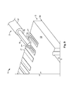
terminal element 3 of the embodiment shown inFig. 1 has generally a plate-like structure having a connecting part 4 and a wire attachment orcontact portion 5. Hence, the terminal element according to this embodiment refers to what is generally known as aterminal connector 3. In the following embodiment, theterminal element 3 will be referred to as aterminal 3. Theterminal 3 of the embodiment has the form of a T-shaped plate, whereby the rectangularly formedcontact portion 5 passes into the middle of the connecting part 4 so that thecontact portion 5 forms the base and the connecting part 4 forms the cross bar of the T-shapedterminal plate 3 according to the embodiment ofFig. 1 . - The connecting part 4 is provided with two attachment holes 6. The attachment holes 6 are designed as through-holes for inserting a bolt or a screw as fastening means for fastening the
terminal 3 to an electric apparatus (not shown). Theterminal 3 of the embodiment shown inFig. 1 is made of a material that conducts electricity so that once theelectric wire 2 is joined with thecontact portion 5 of theterminal 3, the connecting part 4 is electrically connected to thewire 2. - In the
contact portion 5, thecontact opening 7 is provided. Thecontact opening 7 is elongated in the longitudinal direction L of theterminal 3. Thewire 2 is principally aligned with the longitudinal direction L of theterminal 3, in which longitudinal direction L thecontact opening 7 is also elongated. For mechanically and electrically connecting theelectric wire 2 to theterminal 3, at least the connectingportion 8 of thewire 2 is aligned parallel to theentrance surface 9 of thecontact opening 7, whichentrance surface 9 is arranged at theupper side 10 of theterminal 3. Furthermore, the connectingportion 8 of thewire 2, namely the longitudinal axis I of thewire 2 is aligned with the longitudinal direction L of theterminal 3 and theelongated contact opening 7. - In the first embodiment of
Fig. 1 to 3 , thecontact opening 7 is designed as the through-hole 7', extending from theentrance surface 9 at theupper side 10 of thecontact portion 5 up to theexit surface 11 at thelower side 12 of thecontact portion 5. Due to the elongated shape of thecontact opening 7, the through-hole 7' is designed as aslot 7" extending along the longitudinal direction L. The lateral sides 13 of theslot 7" are provided with an undercut 14. In the shown embodiment, the undercut 14 is formed as acavity 15 forming a dent, in which the width w taken along the width direction W of thecontact opening 7 and theterminal 3 is widened. Alternatively, the undercut 14 could be designed by protrusions (not shown) extending from the lateral sides 13 of theslot 7" into thecontact opening 7 thereby reducing the width w of theslot 7" at the position of theundercuts 14. - The
wire 2 of the embodiment ofFig. 1 comprises a solid conductor or lead 16 that is covered on the outside with an insulatingcoating 17 insulating theconductor 16 against the outside. - The connecting
portion 8 of thewire 2 is located at one end of thewire 2. In the connectingportion 8, the insulatingcoating 17 of thewire 2 is removed in the embodiment shown inFig. 1 so that theblank conductor 16 is exposed and can be mechanically and electrically connected to thecontact opening 7, as described in the following by example with reference to the first embodiment of the terminal assembly according toFigs. 1 to 3 . - For mechanically and electrically connecting the
wire 2 to theterminal 3, the joiningsection 18 of the connectingportion 8 is contacted with thecontact opening 7. During the contacting step, the joiningsection 18 is plastically deformed by pressing it into thecontact opening 7, in an insertion or press direction I that is substantially perpendicular to theentrance surface 9 and theupper side 10 of thecontact portion 5 as well as perpendicular to the longitudinal axis I of the alignedwire 2. By pressing in the insertion direction I, the joiningsection 18 enters through theentrance surface 9 into thecontact opening 7. Thereby the lateral cut 19 of the joiningsection 18 is plastically deformed since the width w of thecontact opening 7 of theentrance surface 9 is smaller than the width w the diameter d of theconductor 16. Since theconductor 16 is made from a malleable material, the joiningsection 18 is force-fitted into thecontact opening 7 by contacting the joiningsection 18 with thecontact opening 7. For ensuring a secure non-positive connection between thewire 2 and thecontact opening 7, thelead 16 in the joiningsection 18 has to be provided with sufficient material to allow plastic deformation achieving a non-positive connection due to plastic deformation of thewire 2. - The
terminal assembly 1 of the first embodiment in the assembled state is shown inFigs. 2 and3 . As can be seen inFig. 2 , the joiningsection 18, that is that part of the connectingportion 8 of thewire 2 that is aligned with thecontact opening 17 and is plastically deformed forming the connection between thewire 2 and theterminal 3, substantially fills up thecomplete slot 7" that forms acontact opening 7 in the first embodiment. By filling up thecomplete contact opening 7, the contact area between the deformed joiningsection 18 and thecontact opening 7 is maximized thereby maximizing the force-fit connection between thewire 2 and thecontact opening 7. - The contacting step of plastically deforming the joining
section 18, in the shown embodiment, the step of pressing theconductor 16 into thecontact opening 7 to form the joiningsection 18 can, for example, be conducted by using a deformation or pressing tool (not shown). The pressing tool may comprise a deformation unit (not shown) with a substantially flat surface that presses the connectingportion 8 in the insertion direction I against thecontact portion 5 of theterminal 3 having thecontact opening 7. The joiningsection 18 of thewire 2 that is aligned with acontact opening 7 is deformed such that themalleable lead 16 is pressed into thecontact opening 7, and through thecomplete contact opening 7 from itsentrance surface 9 to itsexit surface 11. After the joiningsection 18 swells out of theexit surface 11, a counter-deformation unit (not shown) is pressed against the insertion direction I from thelower side 12 of thecontact portion 5 against the part of the joiningsection 18 that swells out of theexit surface 11. By compressing the joiningsection 18 from theupper side 11 and from thelower side 12, the lateral cut 19 of the joiningsection 18 is deformed thereby contacting the joiningsection 18 with thecontact opening 7. Thepart 18a of the joiningsection 18 that is situated in thecontact opening 7 after the contacting step forms the non-positive connection of thewire 2 with theterminal 3 that ensures the mechanical and electrical assembling of theterminal assembly 1. Since the volume of the joiningsection 18 is greater than the volume of thecontact opening 7, a part of the joiningsection 18 remains outside thecontact opening 7 at theupper side 10, which part did not enter thecontact opening 7. Another part of the joiningsection 18 that swelled out of theexit surface 11 is also located outside thecontact opening 7 on thelower side 12. - Due to the flat surface of the deformation unit (not shown), pressing the joining
section 18 in the insertion direction I from theupper side 10, the portion at theupper side 10 forms astopper 20 that seals and overlays theentrance surface 9 of thecontact opening 7. Thestopper 20 on theupper side 10 has the shape of a flat plate and extends, in the width direction W and against the width direction W over the lateral sides 13 of the slot 7', thereby forming a form-fit connection of the joiningsection 18, securing thewire 2 in the insertion direction I in thecontact opening 7. - A
similar stopper 20a is formed at thelower side 12 of thecontact portion 5. Thisstopper 20a overlays theexit surface 11 in a similar manner as thestopper 20 overlayers theentrance surface 9 of theupper side 10. Thus, thestopper 20a secures the joiningsection 18 in a form-fit manner in thecontact opening 7 against in the direction opposite to the insertion direction I. - The only difference between the
stopper 20 at theupper side 10 and thestopper 20a at thelower side 12 is that thelower stopper 20a has not a substantially planar shape but is rather formed with twobulges 21 and 21'. One of eachbulge 21, 21' extends over one of thelateral sides 13 at theexit surface 11 of thecontact opening 7. The two bulges 21, 21' meet approximately in the middle of theexit surface 11, so that thestopper 20a at thelower side 12 is provided with acentral groove 22. By forming thestopper 20a with twobulges 20, 20' and a middle channel orgroove 22, the secure form-fit can be formed even with a minimum amount of material of the joiningsection 18 swelling out of theexit surface 11 because less material is required in thechannel 22 and nearly all the swelling out material can be deformed and pressed in and against the width direction W forming the twobulges 21 and 21'. - As can be seen in
Fig. 2 , the remainder of the connectingportion 18 that is not aligned with thecontact opening 7 and therefore does not form the joiningsection 18, is pressed against theupper side 10 of thecontact portion 5 of theterminal 3 forming atransition section 23 that is located between the joiningsection 18 and the remainingwire 2 outside the connecting portion. Since thetransitions section 23 is not pressed into thecontact opening 7, thetransition section 23 is flattened, however, remains higher than thestopper 20 of the joiningsection 18. - In the following, further embodiments of the
terminal assembly 1 are presented. For elements having a similar or identical structure/function as elements of the first embodiment, the same reference signs are used. In the following, only the differences between the further embodiments of theterminal assembly 1 with respect to the first embodiment shown inFigs. 1 to 3 are described. - The second embodiment of the
terminal assembly 1 is shown inFigs. 4A and 4B. Fig. 4A illustrates theterminal assembly 1 comprising thewire 2 and theterminal element 3 in the pre-assembled state. The assembled state, wherein thewire 2 is contacted to thecontact portion 5 of theterminal element 3 can be seen inFig. 4B . - The
terminal assembly 1 of the second embodiment principally corresponds to theterminal assembly 1 of the first embodiment shown inFigs. 1 to 3 . - The only difference is that the connecting
portion 5 of the second embodiment is at thefree end 24, facing away from the connecting portion 4, provided with acrimp barrel 25. Thecrimp barrel 25 is designed, in the pre-assembled state shown inFig. 4A , by a pair of crimpingpieces 26 arranged in a portion having a substantially U-shaped section. The two crimpingpieces 26 form arecess 27, in which thewire 2, having the insulatingcoating 17 can be introduced when assembling theterminal assembly 1. After insertion of thewire 2 in therecess 27, the crimpingpieces 26 are bent with their free ends towards each other embracing and fixing thewire 2 in therecess 27. - By providing the
terminal 3 with a crimpingbarrel 25, an additional joint can be formed between thewire 2 and theterminal element 3. Said additional joint will take up the main load if someone pulls at thewire 2, thereby reducing the tensions at the connection between the joiningsection 18 and theopening 7. -
Figs. 5A and 5B illustrate a third embodiment of theterminal assembly 1 having a wire orcable 2 and aterminal element 3.Fig. 5A shows theterminal assembly 1 of the third embodiment in the pre-assembled state.Fig. 5B displays theterminal assembly 1 of the third embodiment in the assembled state, where thewire 2 is mechanically and electrically connected to theterminal element 3. - The
terminal element 3 of the third embodiment is identical to theterminal element 3 of the first embodiment shown inFigs. 1 to 3 . - Contrary to the
terminal assembly 1 of the first embodiment, theterminal assembly 1 of the third embodiment comprises a magnet wire 2'. The magnet wire 2' is awire conductor 16, usually of copper or aluminium, that is covered with athin insulation 17. Thethin insulation 17 of the magnet wire 2' covers thecomplete lead 16 so that in the pre-assembled state shown inFig. 5A , the connectingportion 8 is also provided with an insulatingcoating 17, contrary to thewire 2 of the first embodiment. - According to the third embodiment of
Figs. 5A and 5B , the insulatingcoating 17 of the wire 2' is removed in the joiningsection 18 during the step of contacting the joiningsection 18 with thecontact opening 7. Since the diameter d of the magnet wire 2' is larger than the width w of the slot 7' forming thecontact opening 7 of theterminal 3, the insulatingcoating 17 is removed from thelead 16 in the joiningsection 18 upon plastically deforming the lateral cut 19 of the joiningsection 18 when contacting said joiningsection 18 with theterminal 3. - As can be seen in
Fig. 5B , only in those sections of the wire 2' that are wider than the width w of the slot 7', theinsulation coating 17 is scraped off and thereby removed, allowing an electrical connection between the lead 16 and theterminal 3. At those sections of the magnet wire 2', that are aligned with thecontact opening 7, and do not extend beyond the lateral sides 13 of the slot 7', theinsulation 17 remain in place as in these sections, theinsulation 17 is not scraped of at theedge 28 of theentrance 9. Therefore, the joiningsection 18 is still isolated at thestoppers upper side 10 and thelower side 12 of theterminal 3. - Finally, it can be seen in
Fig. 5B that the joiningsection 18, upon filing up thecontact opening 7, also fills up thecavities 15 provided at thoselateral sides 13 of theslots 7". Thereby, a further form-fit is provided between the joiningsection 18 and the undercut 14 in thecontact opening 7 which secures the joiningsection 18 against transition of the joiningsection 18 in and against the longitudinal direction L in thecontact opening 7. - The fourth embodiment of the
terminal assembly 1, that is shown inFigs. 6A (pre-assembled state) and 6B (assembled state) comprises aterminal element 3 that is principally identical to theterminal element 3 of the first and third embodiment. Thewire 2 of theterminal assembly 1 is asolid wire 2 similar to thewire 2 of the first embodiment. However, contrary to the first embodiment, the insulatingcoating 17 of thewire 2 in the fourth embodiment extends onto the connectingportion 8 and principally covers thecomplete lead 16. - Similar to an insulation displacement connector, the
terminal 3 of the fourth embodiment ofFigs. 6A and 6B removes theinsulation coating 17 in the joiningsection 18 of thewire 2 upon connecting said joiningsection 18 with thecontact opening 7 of thecontact portion 5 of theterminal 3. Theedge 28 surrounding theentrance surface 9 at theupper side 10 of thecontact portion 5 functions, upon pressing thewire 2 in the insertion direction I against theterminal 3, as a blade that removes theinsulation coating 17 in the joiningsection 18 so that only thelead 16 of the joiningsection 18 is pressed into thecontact opening 7. - In embodiments having a
wire 2 that is provided with an insulatingcoating 17 in the connectingportion 8, aterminal element 3 having a contact opening that is provided with an undercut 14, such as thecavities 15 shown inFig. 5A , has the additional benefit of keeping the insulation at theupper side 10 of theterminal 3 connoted with the cutted insulation at thelower side 12. This avoids pollution in the deformation or pressing tool due to release of the cut insulation into the tool. Further, the insulation remains for thewire 2 on bothsides terminal element 3 even in the joiningsection 18, where the electrical contact is made between the joiningsection 18 and thecontact opening 7. -
Figs. 7A and 7B show a fifth embodiment of aterminal assembly 1, wherein the pre-assembled state is shown inFig. 7A and Fig. 7B depicts the assembled state. - The
terminal element 3 of the fifth embodiment is principally identical to theterminal element 3 of the first embodiment. Furthermore, thewire 2" of the fifth embodiment principally corresponds to thewire 2 of the first embodiment, wherein insulatingcoating 17 is removed in the connectingportion 8 so that ablank lead 16 is exposed to the outside. - In contrast to the
wire 2 of the first embodiment, thewire 2" of the fifth embodiment is a stranded wire that is composed of a bundle of smaller wires making up the conductor. -
Fig. 8 is a schematic representation of a cross-sectional view in the width direction w at a position corresponding to the sectional line A'-A' ofFig. 2 , through thecontact opening 7 of aterminal assembly 1 in the assembled state. As can be seen inFig. 8 , thecontact opening 7 in thecontact portion 5 of theterminal 3 differs from thecontact opening 7 of the previous embodiments in that it is not designed as a through-hole 7'. Rather, thecontact opening 7 of the embodiment shown inFig. 8 is designed as a contact groove or acontact channel 7"' that can be only entered via theentrance surface 9, exposed at theupper side 10 of thecontact portion 5. The shape of theentrance surface 9 may be similar to the shape of theentrance 9 in the previous embodiments and can be designed elongated. - Starting from the
entrance surface 9, the width w of thecontact channel 7"' from onelateral side 13 to the otherlateral side 13, increases up to the bottom 29 of thechannel 7"'. That is, thechannel 7"' principally has a shape of a dovetail, as can be seen inFig. 8 . The lateral sides 13 of thecontact channel 7"' are inclined with respect to the plane defined by the insertion direction I and the longitudinal direction L. Upon filling up thecontact channel 7"' with the joiningsection 18 of thewire 2, the undercut 14 formed by the inclinedlateral walls 13 forms a form-fit connection with the joiningsection 18 securing the part of the joiningsection 18 that is located in thecontact channel 7"' against removal out of thechannel 7"' against the insertion direction I. - Furthermore, the
stopper 20 on theupper side 10 of thecontact portion 5 that overlayers theentrance surface 9 is formed with a curved surface having, in the cross-sectional view, the form of a rivet head, rather than a flat, plate-like shape as in the embodiment ofFig. 1 . - Finally, in
Figs. 9 ,10A and 10B , a seventh embodiment of the terminal assembly is shown. Thewire 2 of the seventh embodiment is generally the same as thewire 2 used in the first embodiment ofFigs. 1 to 3 , namely asolid wire 2 having an insulatingcoating 17 that is removed in the connectingportion 8, where theconductor 16 is exposed to the outside. - The
terminal element 3 in the seventh embodiment is a printedcircuit board 30 having arranged on contact side 31 thereof, a series of spaced apartcontact openings 7. As can be seen, for example, inFig. 10B , thecontact opening 7 of thePCB 30 is designed ascontact channel 7"'. Contrary to thecontact channel 7"' of the sixth embodiment, however, thecontact channels 7 of the seventh embodiment have the constant width w from thesurface entrance 9 up to the bottom 28. - Upon contacting the connecting
portion 8 of thewire 2 to thecontact opening 7 of thePCB 30, the joiningsection 18 is pressed into thecontact opening 7 forming a force-fit connection with thecontact opening 7. The joiningsection 18 is filling up thecomplete channel 7 and the excess portion of the joiningsection 18 that remains outside theopening 7 is flattened into astopper 20, whose shape principally corresponds to thestopper 20 located at theupper side 10 of the first embodiment shown inFig. 1 .
Claims (15)
- Method for mechanically and electrically connecting an electric wire (2) to a terminal element (3) comprising: arranging a connecting portion (8) of the electric wire (2) substantially parallel to an entrance surface (9) of a contact opening (7) of said terminal element (3); and contacting a joining section (18) of the connecting portion (8) with the contact opening (7) by plastically deforming a lateral cut (19) of the joining section (18).
- Method of claim 1, characterized in that the contact opening (7) is elongated, whereby the connecting portion (18) of the electric wire (2) is arranged substantially parallel to the longitudinal direction (L) of the contact opening (7).
- Method of claim 1 or 2, characterized in that the joining section (18) substantially fills up the contact opening (7) during the contacting.
- Method of any one of claims 1 to 3, characterized in that, during contacting, the joining section (18) outside the contact opening (7) is overlaying the entrance surface (9).
- Method of any one of claims 1 to 4, characterized in that, for contacting, the joining section (18) is pressed into the contact opening (7) in an insertion direction (I) that runs substantially perpendicular to the entrance surface (9) of the contact opening (7).
- Method of any one of claims 1 to 5, characterized in that an insulating coating (17) of the wire (2) is removed in the joining section (18) during contacting the joining section (18) with the contact opening (7).
- Terminal assembly (1) comprising a terminal element (3) having at least one contact opening (7), and at least one electric wire (2) that is mechanically and electrically connected to the contact opening (7), wherein a connecting portion (8) of the electric wire (2) that is located outside the contact opening (7) runs substantially parallel to an entrance surface (9) of the contact opening (7), and wherein a joining section (18) of the connecting portion (8) is plastically deformed into and thereby non-positively connected to the contact opening (7).
- Terminal assembly (1) according to claim 7, characterized in that the contact opening (7) is elongated in the direction of the electrical wire (2).
- Terminal assembly (1) according to claim 7 or 8, characterized in that the contact opening (7) is provided with at least one undercut (14).
- Terminal assembly (1) according to anyone of claims 7 to 9, characterized in that the contact opening (7) is formed by a through-hole (7') extending from the entrance surface (9) on one side (10) of the terminal element (3) to an exit surface (11) on another side (12) of the terminal element (3).
- Terminal assembly (1) according to claim 10, characterized in that the joining section (18) extends through the through-hole (7') and is provided with a stopper (20) overlaying the entrance surface (9) at the upper side (10) and a further stopper (20a) overlaying the exit surface (11) on the lower side (12) of the terminal element (3).
- Terminal assembly (1) according to any one of claims 7 to 11, characterized in that the wire (2) is a solid wire (2), a magnet wire (2') or a stranded wire (2").
- Terminal assembly (1) according to any one of claims 7 to 12, characterized in that the volume of the wire (2) in the joining section (18) is greater than the volume of the contact opening (7).
- Method for producing an electrical device comprising the method for mechanically and electrically connecting an electric wire (2) to a terminal element (3) according to anyone of claims 1 to 6.
- Electrical device comprising a terminal assembly (1) according to anyone of claims 7 to 13.
Priority Applications (5)
| Application Number | Priority Date | Filing Date | Title |
|---|---|---|---|
| EP10192412.4A EP2458694B1 (en) | 2010-11-24 | 2010-11-24 | Terminal assembly and method for connecting an electric wire to a terminal element |
| US13/989,353 US20130244511A1 (en) | 2010-11-24 | 2011-11-14 | Terminal assembly and method for connecting an electric wire to a terminal element |
| JP2013540298A JP2014502018A (en) | 2010-11-24 | 2011-11-14 | Method for connecting terminal assembly and electric wire to terminal member |
| CN2011800563434A CN103222131A (en) | 2010-11-24 | 2011-11-14 | Terminal assembly and method for connecting an electric wire to a terminal element |
| PCT/EP2011/070013 WO2012069328A1 (en) | 2010-11-24 | 2011-11-14 | Terminal assembly and method for connecting an electric wire to a terminal element |
Applications Claiming Priority (1)
| Application Number | Priority Date | Filing Date | Title |
|---|---|---|---|
| EP10192412.4A EP2458694B1 (en) | 2010-11-24 | 2010-11-24 | Terminal assembly and method for connecting an electric wire to a terminal element |
Publications (2)
| Publication Number | Publication Date |
|---|---|
| EP2458694A1 true EP2458694A1 (en) | 2012-05-30 |
| EP2458694B1 EP2458694B1 (en) | 2013-06-26 |
Family
ID=43734106
Family Applications (1)
| Application Number | Title | Priority Date | Filing Date |
|---|---|---|---|
| EP10192412.4A Not-in-force EP2458694B1 (en) | 2010-11-24 | 2010-11-24 | Terminal assembly and method for connecting an electric wire to a terminal element |
Country Status (5)
| Country | Link |
|---|---|
| US (1) | US20130244511A1 (en) |
| EP (1) | EP2458694B1 (en) |
| JP (1) | JP2014502018A (en) |
| CN (1) | CN103222131A (en) |
| WO (1) | WO2012069328A1 (en) |
Cited By (1)
| Publication number | Priority date | Publication date | Assignee | Title |
|---|---|---|---|---|
| WO2013167846A1 (en) | 2012-05-11 | 2013-11-14 | Legrand France | Mechanical assembly by means of autogenous riveting |
Families Citing this family (5)
| Publication number | Priority date | Publication date | Assignee | Title |
|---|---|---|---|---|
| US10418771B2 (en) * | 2014-03-18 | 2019-09-17 | Diego FIN | Method and device for applying an electrical terminal to one or more electrical conductors, whether insulated or not, and electrical terminal suitable for this purpose |
| DE102014115393B3 (en) * | 2014-10-22 | 2016-04-07 | Actuator Solutions GmbH | Connecting arrangement with a crimp connector and a fixed in this wire |
| CN104733979B (en) * | 2015-03-13 | 2017-01-11 | 苏州和德精密电子有限公司 | Manufacturing device and method for USB connectors |
| JP6766437B2 (en) * | 2016-05-10 | 2020-10-14 | 株式会社オートネットワーク技術研究所 | Wires with terminals and terminals |
| US20220368052A1 (en) * | 2021-05-12 | 2022-11-17 | Aptiv Technologies Limited | High voltage (hv) terminal frame |
Citations (6)
| Publication number | Priority date | Publication date | Assignee | Title |
|---|---|---|---|---|
| FR1049522A (en) * | 1950-10-21 | 1953-12-30 | Philips Nv | Electrical connection |
| FR1279798A (en) * | 1961-02-01 | 1961-12-22 | Amp Inc | Electrical connection and method for its execution |
| US3355698A (en) * | 1965-04-28 | 1967-11-28 | Amp Inc | Electrical connector |
| GB1505676A (en) * | 1974-04-26 | 1978-03-30 | Amp Inc | Electrical terminals and connectors |
| WO1990001817A1 (en) * | 1988-07-29 | 1990-02-22 | Ab Konstruktions-Bakelit | Contact pin and method for connecting an electric wire to such a pin |
| FR2935550A1 (en) * | 2008-09-03 | 2010-03-05 | Legrand Snc | ELECTRICAL AND MECHANICAL ASSEMBLY OBTAINED BY AUTOGENOUS RIVETTING |
Family Cites Families (2)
| Publication number | Priority date | Publication date | Assignee | Title |
|---|---|---|---|---|
| GB1407311A (en) * | 1972-09-11 | 1975-09-24 | Amp Inc | Electrical connector |
| CN1268042C (en) * | 2001-02-22 | 2006-08-02 | 金马达制造厂有限公司 | Method for crimping thermal protection devices |
-
2010
- 2010-11-24 EP EP10192412.4A patent/EP2458694B1/en not_active Not-in-force
-
2011
- 2011-11-14 WO PCT/EP2011/070013 patent/WO2012069328A1/en not_active Ceased
- 2011-11-14 JP JP2013540298A patent/JP2014502018A/en active Pending
- 2011-11-14 US US13/989,353 patent/US20130244511A1/en not_active Abandoned
- 2011-11-14 CN CN2011800563434A patent/CN103222131A/en active Pending
Patent Citations (6)
| Publication number | Priority date | Publication date | Assignee | Title |
|---|---|---|---|---|
| FR1049522A (en) * | 1950-10-21 | 1953-12-30 | Philips Nv | Electrical connection |
| FR1279798A (en) * | 1961-02-01 | 1961-12-22 | Amp Inc | Electrical connection and method for its execution |
| US3355698A (en) * | 1965-04-28 | 1967-11-28 | Amp Inc | Electrical connector |
| GB1505676A (en) * | 1974-04-26 | 1978-03-30 | Amp Inc | Electrical terminals and connectors |
| WO1990001817A1 (en) * | 1988-07-29 | 1990-02-22 | Ab Konstruktions-Bakelit | Contact pin and method for connecting an electric wire to such a pin |
| FR2935550A1 (en) * | 2008-09-03 | 2010-03-05 | Legrand Snc | ELECTRICAL AND MECHANICAL ASSEMBLY OBTAINED BY AUTOGENOUS RIVETTING |
Cited By (3)
| Publication number | Priority date | Publication date | Assignee | Title |
|---|---|---|---|---|
| WO2013167846A1 (en) | 2012-05-11 | 2013-11-14 | Legrand France | Mechanical assembly by means of autogenous riveting |
| FR2990568A1 (en) * | 2012-05-11 | 2013-11-15 | Legrand France | MECHANICAL ASSEMBLY BY AUTOGENOUS RIVET |
| US10395801B2 (en) | 2012-05-11 | 2019-08-27 | Legrand France | Mechanical assembly by means of autogenous riveting |
Also Published As
| Publication number | Publication date |
|---|---|
| CN103222131A (en) | 2013-07-24 |
| EP2458694B1 (en) | 2013-06-26 |
| WO2012069328A1 (en) | 2012-05-31 |
| US20130244511A1 (en) | 2013-09-19 |
| JP2014502018A (en) | 2014-01-23 |
Similar Documents
| Publication | Publication Date | Title |
|---|---|---|
| EP1921713B1 (en) | Insulation displacement connector assembly and system adapted for surface mounting on printed circuitboard and method of using the same | |
| KR101624065B1 (en) | Connecting structure and connecting method of flat circuit body and terminal | |
| EP2458694B1 (en) | Terminal assembly and method for connecting an electric wire to a terminal element | |
| KR20040007513A (en) | Method and apparatus for using a flat flexible cable connector | |
| EP3425735B1 (en) | Crimp connection terminal and production method therefor | |
| US9083091B1 (en) | Electrical terminal connector for solderless connection of parts to electrical contact holes | |
| EP2159880A1 (en) | A terminal fitting and a wire connected with a terminal fitting | |
| US7316581B2 (en) | Terminal fitting and method of attaching the same | |
| US20190140375A1 (en) | Plug contact | |
| US20080242139A1 (en) | Connector and Line Connecting Method Thereof | |
| CN104904067A (en) | Electric wire with terminal, and method for manufacturing electric wire with terminal | |
| US20140065876A1 (en) | Method and apparatus of manufacturing a cable assembly | |
| US7244139B2 (en) | Electric connector and method for manufacturing the same | |
| US11296440B2 (en) | Electrical terminal for flat flexible cables | |
| JP5146759B2 (en) | Terminal fitting, electric wire with terminal fitting, and manufacturing method of electric wire with terminal fitting | |
| JP4977768B2 (en) | Manufacturing method of multiple types of terminal fittings | |
| JP4102295B2 (en) | Piercing terminal for coaxial cable | |
| JP4247180B2 (en) | Electrical connector | |
| EP1662615A2 (en) | Electric connector | |
| US20220006214A1 (en) | Electrical Terminal For Flat Flexible Cables | |
| JP3852920B2 (en) | Piercing terminal connection structure | |
| JP4844496B2 (en) | Manufacturing method of conductive material and electric junction box for automobile containing conductive material | |
| EP0951095A2 (en) | Electrical connector | |
| JP2008306819A (en) | Conductive material | |
| JP2532536Y2 (en) | Electrical connection structure of branch junction box |
Legal Events
| Date | Code | Title | Description |
|---|---|---|---|
| PUAI | Public reference made under article 153(3) epc to a published international application that has entered the european phase |
Free format text: ORIGINAL CODE: 0009012 |
|
| 17P | Request for examination filed |
Effective date: 20110630 |
|
| AK | Designated contracting states |
Kind code of ref document: A1 Designated state(s): AL AT BE BG CH CY CZ DE DK EE ES FI FR GB GR HR HU IE IS IT LI LT LU LV MC MK MT NL NO PL PT RO RS SE SI SK SM TR |
|
| AX | Request for extension of the european patent |
Extension state: BA ME |
|
| GRAP | Despatch of communication of intention to grant a patent |
Free format text: ORIGINAL CODE: EPIDOSNIGR1 |
|
| REG | Reference to a national code |
Ref country code: DE Ref legal event code: R079 Ref document number: 602010008026 Country of ref document: DE Free format text: PREVIOUS MAIN CLASS: H01R0043040000 Ipc: H01R0004100000 |
|
| GRAP | Despatch of communication of intention to grant a patent |
Free format text: ORIGINAL CODE: EPIDOSNIGR1 |
|
| RIC1 | Information provided on ipc code assigned before grant |
Ipc: H01R 4/10 20060101AFI20130114BHEP Ipc: H05K 3/32 20060101ALI20130114BHEP Ipc: H01R 43/04 20060101ALI20130114BHEP |
|
| GRAS | Grant fee paid |
Free format text: ORIGINAL CODE: EPIDOSNIGR3 |
|
| GRAA | (expected) grant |
Free format text: ORIGINAL CODE: 0009210 |
|
| AK | Designated contracting states |
Kind code of ref document: B1 Designated state(s): AL AT BE BG CH CY CZ DE DK EE ES FI FR GB GR HR HU IE IS IT LI LT LU LV MC MK MT NL NO PL PT RO RS SE SI SK SM TR |
|
| REG | Reference to a national code |
Ref country code: GB Ref legal event code: FG4D |
|
| REG | Reference to a national code |
Ref country code: CH Ref legal event code: EP |
|
| REG | Reference to a national code |
Ref country code: AT Ref legal event code: REF Ref document number: 619052 Country of ref document: AT Kind code of ref document: T Effective date: 20130715 |
|
| REG | Reference to a national code |
Ref country code: IE Ref legal event code: FG4D |
|
| REG | Reference to a national code |
Ref country code: DE Ref legal event code: R096 Ref document number: 602010008026 Country of ref document: DE Effective date: 20130822 |
|
| REG | Reference to a national code |
Ref country code: NL Ref legal event code: T3 |
|
| PG25 | Lapsed in a contracting state [announced via postgrant information from national office to epo] |
Ref country code: FI Free format text: LAPSE BECAUSE OF FAILURE TO SUBMIT A TRANSLATION OF THE DESCRIPTION OR TO PAY THE FEE WITHIN THE PRESCRIBED TIME-LIMIT Effective date: 20130626 Ref country code: SI Free format text: LAPSE BECAUSE OF FAILURE TO SUBMIT A TRANSLATION OF THE DESCRIPTION OR TO PAY THE FEE WITHIN THE PRESCRIBED TIME-LIMIT Effective date: 20130626 Ref country code: GR Free format text: LAPSE BECAUSE OF FAILURE TO SUBMIT A TRANSLATION OF THE DESCRIPTION OR TO PAY THE FEE WITHIN THE PRESCRIBED TIME-LIMIT Effective date: 20130927 Ref country code: SE Free format text: LAPSE BECAUSE OF FAILURE TO SUBMIT A TRANSLATION OF THE DESCRIPTION OR TO PAY THE FEE WITHIN THE PRESCRIBED TIME-LIMIT Effective date: 20130626 Ref country code: LT Free format text: LAPSE BECAUSE OF FAILURE TO SUBMIT A TRANSLATION OF THE DESCRIPTION OR TO PAY THE FEE WITHIN THE PRESCRIBED TIME-LIMIT Effective date: 20130626 Ref country code: NO Free format text: LAPSE BECAUSE OF FAILURE TO SUBMIT A TRANSLATION OF THE DESCRIPTION OR TO PAY THE FEE WITHIN THE PRESCRIBED TIME-LIMIT Effective date: 20130926 |
|
| REG | Reference to a national code |
Ref country code: AT Ref legal event code: MK05 Ref document number: 619052 Country of ref document: AT Kind code of ref document: T Effective date: 20130626 |
|
| REG | Reference to a national code |
Ref country code: LT Ref legal event code: MG4D |
|
| PG25 | Lapsed in a contracting state [announced via postgrant information from national office to epo] |
Ref country code: HR Free format text: LAPSE BECAUSE OF FAILURE TO SUBMIT A TRANSLATION OF THE DESCRIPTION OR TO PAY THE FEE WITHIN THE PRESCRIBED TIME-LIMIT Effective date: 20130626 Ref country code: RS Free format text: LAPSE BECAUSE OF FAILURE TO SUBMIT A TRANSLATION OF THE DESCRIPTION OR TO PAY THE FEE WITHIN THE PRESCRIBED TIME-LIMIT Effective date: 20130626 Ref country code: BG Free format text: LAPSE BECAUSE OF FAILURE TO SUBMIT A TRANSLATION OF THE DESCRIPTION OR TO PAY THE FEE WITHIN THE PRESCRIBED TIME-LIMIT Effective date: 20130926 |
|
| PG25 | Lapsed in a contracting state [announced via postgrant information from national office to epo] |
Ref country code: LV Free format text: LAPSE BECAUSE OF FAILURE TO SUBMIT A TRANSLATION OF THE DESCRIPTION OR TO PAY THE FEE WITHIN THE PRESCRIBED TIME-LIMIT Effective date: 20130626 |
|
| PG25 | Lapsed in a contracting state [announced via postgrant information from national office to epo] |
Ref country code: AT Free format text: LAPSE BECAUSE OF FAILURE TO SUBMIT A TRANSLATION OF THE DESCRIPTION OR TO PAY THE FEE WITHIN THE PRESCRIBED TIME-LIMIT Effective date: 20130626 Ref country code: BE Free format text: LAPSE BECAUSE OF FAILURE TO SUBMIT A TRANSLATION OF THE DESCRIPTION OR TO PAY THE FEE WITHIN THE PRESCRIBED TIME-LIMIT Effective date: 20130626 Ref country code: EE Free format text: LAPSE BECAUSE OF FAILURE TO SUBMIT A TRANSLATION OF THE DESCRIPTION OR TO PAY THE FEE WITHIN THE PRESCRIBED TIME-LIMIT Effective date: 20130626 Ref country code: IS Free format text: LAPSE BECAUSE OF FAILURE TO SUBMIT A TRANSLATION OF THE DESCRIPTION OR TO PAY THE FEE WITHIN THE PRESCRIBED TIME-LIMIT Effective date: 20131026 Ref country code: PT Free format text: LAPSE BECAUSE OF FAILURE TO SUBMIT A TRANSLATION OF THE DESCRIPTION OR TO PAY THE FEE WITHIN THE PRESCRIBED TIME-LIMIT Effective date: 20131028 Ref country code: CZ Free format text: LAPSE BECAUSE OF FAILURE TO SUBMIT A TRANSLATION OF THE DESCRIPTION OR TO PAY THE FEE WITHIN THE PRESCRIBED TIME-LIMIT Effective date: 20130626 Ref country code: CY Free format text: LAPSE BECAUSE OF FAILURE TO SUBMIT A TRANSLATION OF THE DESCRIPTION OR TO PAY THE FEE WITHIN THE PRESCRIBED TIME-LIMIT Effective date: 20130828 Ref country code: SK Free format text: LAPSE BECAUSE OF FAILURE TO SUBMIT A TRANSLATION OF THE DESCRIPTION OR TO PAY THE FEE WITHIN THE PRESCRIBED TIME-LIMIT Effective date: 20130626 |
|
| PG25 | Lapsed in a contracting state [announced via postgrant information from national office to epo] |
Ref country code: RO Free format text: LAPSE BECAUSE OF FAILURE TO SUBMIT A TRANSLATION OF THE DESCRIPTION OR TO PAY THE FEE WITHIN THE PRESCRIBED TIME-LIMIT Effective date: 20130626 Ref country code: ES Free format text: LAPSE BECAUSE OF FAILURE TO SUBMIT A TRANSLATION OF THE DESCRIPTION OR TO PAY THE FEE WITHIN THE PRESCRIBED TIME-LIMIT Effective date: 20131007 Ref country code: PL Free format text: LAPSE BECAUSE OF FAILURE TO SUBMIT A TRANSLATION OF THE DESCRIPTION OR TO PAY THE FEE WITHIN THE PRESCRIBED TIME-LIMIT Effective date: 20130626 |
|
| PG25 | Lapsed in a contracting state [announced via postgrant information from national office to epo] |
Ref country code: CY Free format text: LAPSE BECAUSE OF FAILURE TO SUBMIT A TRANSLATION OF THE DESCRIPTION OR TO PAY THE FEE WITHIN THE PRESCRIBED TIME-LIMIT Effective date: 20130626 |
|
| PG25 | Lapsed in a contracting state [announced via postgrant information from national office to epo] |
Ref country code: DK Free format text: LAPSE BECAUSE OF FAILURE TO SUBMIT A TRANSLATION OF THE DESCRIPTION OR TO PAY THE FEE WITHIN THE PRESCRIBED TIME-LIMIT Effective date: 20130626 |
|
| PLBE | No opposition filed within time limit |
Free format text: ORIGINAL CODE: 0009261 |
|
| STAA | Information on the status of an ep patent application or granted ep patent |
Free format text: STATUS: NO OPPOSITION FILED WITHIN TIME LIMIT |
|
| 26N | No opposition filed |
Effective date: 20140327 |
|
| REG | Reference to a national code |
Ref country code: DE Ref legal event code: R097 Ref document number: 602010008026 Country of ref document: DE Effective date: 20140327 |
|
| PG25 | Lapsed in a contracting state [announced via postgrant information from national office to epo] |
Ref country code: MC Free format text: LAPSE BECAUSE OF FAILURE TO SUBMIT A TRANSLATION OF THE DESCRIPTION OR TO PAY THE FEE WITHIN THE PRESCRIBED TIME-LIMIT Effective date: 20130626 |
|
| REG | Reference to a national code |
Ref country code: IE Ref legal event code: MM4A |
|
| PG25 | Lapsed in a contracting state [announced via postgrant information from national office to epo] |
Ref country code: IE Free format text: LAPSE BECAUSE OF NON-PAYMENT OF DUE FEES Effective date: 20131124 |
|
| PGFP | Annual fee paid to national office [announced via postgrant information from national office to epo] |
Ref country code: FR Payment date: 20141118 Year of fee payment: 5 |
|
| PGFP | Annual fee paid to national office [announced via postgrant information from national office to epo] |
Ref country code: NL Payment date: 20141126 Year of fee payment: 5 |
|
| PGFP | Annual fee paid to national office [announced via postgrant information from national office to epo] |
Ref country code: IT Payment date: 20141124 Year of fee payment: 5 |
|
| PG25 | Lapsed in a contracting state [announced via postgrant information from national office to epo] |
Ref country code: SM Free format text: LAPSE BECAUSE OF FAILURE TO SUBMIT A TRANSLATION OF THE DESCRIPTION OR TO PAY THE FEE WITHIN THE PRESCRIBED TIME-LIMIT Effective date: 20130626 |
|
| PG25 | Lapsed in a contracting state [announced via postgrant information from national office to epo] |
Ref country code: TR Free format text: LAPSE BECAUSE OF FAILURE TO SUBMIT A TRANSLATION OF THE DESCRIPTION OR TO PAY THE FEE WITHIN THE PRESCRIBED TIME-LIMIT Effective date: 20130626 |
|
| REG | Reference to a national code |
Ref country code: CH Ref legal event code: PL |
|
| GBPC | Gb: european patent ceased through non-payment of renewal fee |
Effective date: 20141124 |
|
| PG25 | Lapsed in a contracting state [announced via postgrant information from national office to epo] |
Ref country code: LU Free format text: LAPSE BECAUSE OF NON-PAYMENT OF DUE FEES Effective date: 20131124 Ref country code: CH Free format text: LAPSE BECAUSE OF NON-PAYMENT OF DUE FEES Effective date: 20141130 Ref country code: LI Free format text: LAPSE BECAUSE OF NON-PAYMENT OF DUE FEES Effective date: 20141130 Ref country code: MK Free format text: LAPSE BECAUSE OF FAILURE TO SUBMIT A TRANSLATION OF THE DESCRIPTION OR TO PAY THE FEE WITHIN THE PRESCRIBED TIME-LIMIT Effective date: 20130626 Ref country code: HU Free format text: LAPSE BECAUSE OF FAILURE TO SUBMIT A TRANSLATION OF THE DESCRIPTION OR TO PAY THE FEE WITHIN THE PRESCRIBED TIME-LIMIT; INVALID AB INITIO Effective date: 20101124 |
|
| PG25 | Lapsed in a contracting state [announced via postgrant information from national office to epo] |
Ref country code: MT Free format text: LAPSE BECAUSE OF FAILURE TO SUBMIT A TRANSLATION OF THE DESCRIPTION OR TO PAY THE FEE WITHIN THE PRESCRIBED TIME-LIMIT Effective date: 20130626 |
|
| PG25 | Lapsed in a contracting state [announced via postgrant information from national office to epo] |
Ref country code: GB Free format text: LAPSE BECAUSE OF NON-PAYMENT OF DUE FEES Effective date: 20141124 |
|
| PG25 | Lapsed in a contracting state [announced via postgrant information from national office to epo] |
Ref country code: IT Free format text: LAPSE BECAUSE OF NON-PAYMENT OF DUE FEES Effective date: 20151124 |
|
| REG | Reference to a national code |
Ref country code: NL Ref legal event code: MM Effective date: 20151201 |
|
| REG | Reference to a national code |
Ref country code: FR Ref legal event code: ST Effective date: 20160729 |
|
| PG25 | Lapsed in a contracting state [announced via postgrant information from national office to epo] |
Ref country code: NL Free format text: LAPSE BECAUSE OF NON-PAYMENT OF DUE FEES Effective date: 20151201 |
|
| PG25 | Lapsed in a contracting state [announced via postgrant information from national office to epo] |
Ref country code: FR Free format text: LAPSE BECAUSE OF NON-PAYMENT OF DUE FEES Effective date: 20151130 |
|
| PG25 | Lapsed in a contracting state [announced via postgrant information from national office to epo] |
Ref country code: AL Free format text: LAPSE BECAUSE OF FAILURE TO SUBMIT A TRANSLATION OF THE DESCRIPTION OR TO PAY THE FEE WITHIN THE PRESCRIBED TIME-LIMIT Effective date: 20130626 |
|
| PGFP | Annual fee paid to national office [announced via postgrant information from national office to epo] |
Ref country code: DE Payment date: 20181113 Year of fee payment: 9 |
|
| REG | Reference to a national code |
Ref country code: DE Ref legal event code: R119 Ref document number: 602010008026 Country of ref document: DE |
|
| PG25 | Lapsed in a contracting state [announced via postgrant information from national office to epo] |
Ref country code: DE Free format text: LAPSE BECAUSE OF NON-PAYMENT OF DUE FEES Effective date: 20200603 |