EP2460602A1 - Dispositif d'alimentation en rivets - Google Patents
Dispositif d'alimentation en rivets Download PDFInfo
- Publication number
- EP2460602A1 EP2460602A1 EP11180858A EP11180858A EP2460602A1 EP 2460602 A1 EP2460602 A1 EP 2460602A1 EP 11180858 A EP11180858 A EP 11180858A EP 11180858 A EP11180858 A EP 11180858A EP 2460602 A1 EP2460602 A1 EP 2460602A1
- Authority
- EP
- European Patent Office
- Prior art keywords
- rivet
- downstream
- transfer
- elements
- control unit
- Prior art date
- Legal status (The legal status is an assumption and is not a legal conclusion. Google has not performed a legal analysis and makes no representation as to the accuracy of the status listed.)
- Granted
Links
- 238000000034 method Methods 0.000 claims abstract description 9
- 238000011144 upstream manufacturing Methods 0.000 claims description 10
- 239000012530 fluid Substances 0.000 description 19
- 230000000903 blocking effect Effects 0.000 description 5
- 230000006870 function Effects 0.000 description 3
- 230000000694 effects Effects 0.000 description 2
- 230000007704 transition Effects 0.000 description 2
- 230000006978 adaptation Effects 0.000 description 1
- 238000010276 construction Methods 0.000 description 1
- 230000008878 coupling Effects 0.000 description 1
- 238000010168 coupling process Methods 0.000 description 1
- 238000005859 coupling reaction Methods 0.000 description 1
- 239000000463 material Substances 0.000 description 1
- 230000000149 penetrating effect Effects 0.000 description 1
- 230000035515 penetration Effects 0.000 description 1
- 238000007789 sealing Methods 0.000 description 1
- 238000013022 venting Methods 0.000 description 1
Images


Classifications
-
- B—PERFORMING OPERATIONS; TRANSPORTING
- B21—MECHANICAL METAL-WORKING WITHOUT ESSENTIALLY REMOVING MATERIAL; PUNCHING METAL
- B21J—FORGING; HAMMERING; PRESSING METAL; RIVETING; FORGE FURNACES
- B21J15/00—Riveting
- B21J15/10—Riveting machines
- B21J15/30—Particular elements, e.g. supports; Suspension equipment specially adapted for portable riveters
- B21J15/32—Devices for inserting or holding rivets in position with or without feeding arrangements
Definitions
- the invention relates to a rivet provisioning device for providing rivet elements o.
- a rivet provisioning device for providing rivet elements o.
- the like According to claim 1, an arrangement of at least two Nietr eins wornen according to claim 6 and a method for the operation of such an arrangement according to claim 9.
- Rivet connections have been playing an important role for many years, above all in the aviation industry.
- the automation of riveting applications with regard to the ever-increasing number of aircraft components is becoming increasingly important.
- a known rivet delivery device (EP 1 531 966 B1 ) is equipped with a designed as a cassette rivet storage, which has a number of stacked rivet cassettes. By means of a transfer carriage, which can be moved along the rivet cassettes, rivet elements are transferred from the respective rivet cassette to a rivet outlet.
- a disadvantage of the known rivet provisioning device is the fact that their storage capacity is limited by the maximum stacking height of the rivet cassettes. An extension of the rivet memory is associated with considerable design effort.
- the invention is based on the problem to design the known Nietrgnas issued such and further, that the total available storage capacity is increased by simple structural means.
- the rivet provisioning device also has at least one rivet inlet in addition to the at least one rivet outlet.
- the arrangement according to the proposal is made such that a rivet element provided at a rivet entrance can be passed to a rivet outlet.
- the transfer carriage of the rivet provisioning device is used to implement the passage through the rivet elements. This double use of the transfer carriage leads to a compact and structurally comparatively simple solution.
- Rivet elements 1 stored in the rivet delivery device R are preferably transferred to a rivet control when used as intended, received by the rivet control and transported on to the respective riveting application.
- the rivet preparation device R is preferably equipped with a very special rivet control. An explanation of its preferred embodiment is now prefaced in the sense of a complete presentation.
- the movement control of the rivet elements 1 comprises both an active driving of the rivet elements 1 and a passive locking or releasing the rivet elements 1.
- the rivet control preferably occurs the function of receiving and forwarding rivet elements 1 to, as will be shown.
- the term "motion control" is to be understood far.
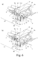
- the Fig. 5 to 7 show a preferred rivet control, here and preferably in the in the Fig. 1 to 4 illustrated rivet delivery device R application finds.
- the rivet control is fundamentally modular and has at least one rivet control unit 2, in this case a total of six rivet control units 2.
- the structure of a rivet control unit 2 can be seen in the illustrations Fig. 6 remove. In the following, in the sense of a clear representation, there is almost all talk of only a single rivet control unit 2. All statements on this rivet control unit 2 apply correspondingly to all other rivet control units 2 of the rivet control system.
- each rivet control unit 2 is equipped with a rivet channel 3, through which the respective rivet elements 1 can be advanced.
- the transport of the rivet elements 1 takes place here and preferably via a fluid flow, which is introduced into the respective section of the rivet channel 3.
- the fluid in the simplest case is air.
- the rivet channel 3 has an input section 3a for receiving rivet elements 1 and an output section 3b.
- the rivet elements 1 accordingly run in the conveying direction 4 from the inlet section 3a to the outlet section 3b and from there to the respective rivet application.
- the rivet control unit 2 of the proposed rivet control has a control shaft 5, which penetrates the rivet channel 3 in a control region 6 between the input section 3a and the output section 3b. It may in principle be provided that the control shaft 5 penetrates only a part of the rivet channel 3. Here and preferably, however, a penetration of the complete Nietkanals 3, more preferably substantially transverse to the Nietkanal longitudinal axis 7, is provided.
- control shaft 5 acts here in the manner of a shut-off valve. Accordingly, the control shaft 5 in the in Fig. 6a illustrated passage position for a rivet 1 and fluid open connection portion 8 between the input portion 3a and the output portion 3b ready.
- Fig. 6b shows that the control shaft 5 in a blocking position substantially blocks the passage of rivet elements 1 and / or fluid between the inlet section 3a and the outlet section 3b.
- the control shaft 5 a in Fig. 6 Nietkanal-Durchgangsbohrung 9 shown, whose cross section substantially corresponds to the cross section of the Nietkanals 3 in the input section 3a and / or in the output section 3b.
- the rivet passage through-hole 9 provides the above-mentioned connecting portion 8 between the input portion 3a and the output portion 3b of the rivet channel 3, or blocks the rivet passage through-hole 9 from penetrating rivet members 1 and / or fluid between the input portion 3a and the output section 3b.
- the function of the rivet control unit 2 is not limited to the pure function of a shut-off valve. Rather, the rivet control unit 2 has a transfer conveyor 10, which serves to convey a rivet element 1 from the inlet section 3a into the outlet section 3b by means of a transfer fluid flow 11 ( Fig. 6a ).
- the transfer conveyor 10 has a plurality of fluid channels 12, which communicate with the inlet section 3a of the rivet channel 3 and over which the transfer fluid flow 11 can be generated.
- the fluid channels 12 are coupled to a corresponding fluid supply 12a.
- the direction of the transfer fluid flow 11 is due to the orientation of the fluid channels 12, which are shown in FIG Fig. 6 results.
- the transfer conveyor 10 in the region of the control shaft 5, at least one vent opening 14 through which at least a portion of the transfer fluid flow 11 flows.
- the control shaft 5 has a series of venting grooves 14 opening into an outlet opening 9a of the rivet passage through-bore 9 ( Fig. 6 . 7 ).
- the rivet control unit 2 is equipped with a transport conveyor 15 for the further transport of a rivet element 1 from the outlet section 3b for riveting application by means of a transport fluid flow 16.
- the transport of the rivet element 1 takes place in the in Fig. 6b ) illustrated constellation.
- control shaft 5 in the blocking position as already indicated provide a different density.
- control shaft 5 is provided with a sealing surface 18, which serves to seal against the housing 19 of the rivet control unit 2.
- Fig. 7 shows that in the illustrated and so far preferred embodiment, several control shafts 5 have been combined to form a common control shaft 21 are. This takes into account the fact that here at least two adjacently arranged rivet control units 2, in total a total of six juxtaposed rivet control units 2, are provided, wherein the control shafts 5 of the rivet control units 2 are each provided by an axial portion of the common control shaft 21.
- the rivet provision device R serves, as already explained, to provide rivet elements 1 or the like. for at least one riveting application.
- Fig. 2 it is indicated that the riveting application is being implemented by an automated riveting tool N.
- Fig. 2 further shows that there are two rivet provisioning devices R connected in series, which will be explained below.
- the rivet provision device R has a rivet storage 24 in which preferably different rivet elements 1 can be stored. Furthermore, the rivet delivery device R has at least one rivet outlet 25, in this case a total of 6 rivet outlets 25.
- the rivet storage 25 is here in the manner of a cassette cabinet equipped with at least two stacked, in particular exchangeable rivet cassettes 26, each having at least one output flange 27 o.
- the like For dispensing rivet elements 1.
- the output flange 27 of the rivet cassette 26 can be designed differently.
- the output flange 27 is designed like a tube, as shown in FIG Fig. 3a ) can be seen.
- a transfer carriage 28 which has a rivet control explained above with here and preferably a plurality of rivet control units 2.
- the rivet control units 2 are each designed for different rivet elements 1, so that, depending on which rivet element 1 is to be transferred, the suitable rivet control unit 2 is used.
- the transfer carriage 28 is as in Fig. 4 shown arranged on a central mounting plate.
- the transfer carriage 28 can be moved along the rivet cassettes 26 in its stacking direction 29.
- a rivet control unit 2 of the rivet control can be aligned with a rivet cassette 26 for transferring a rivet element 1 from the respective rivet cassette 26 to the respective rivet control unit 2.
- each rivet control unit 2 has an input flange 30 for receiving rivet elements 1 assigned to the input section 3a of the rivet channel 3, wherein the rivet-cassette-side output flange 27 and the rivet-control-side input flange 30 are spaced apart by a gap when transferring a rivet element 1.
- FIG. 4 shows in the lower detail view, as the rivet-cassette-side output flange 27 is positioned opposite the rivet control and the local input flanges 30. Since there is always a gap between the rivet cassette-side output flanges 27 and the rivet-control-side input flanges 30, it is sufficient to move the transfer carriage 28 and the rivet controller as a whole in only a single degree of freedom. In order to ensure an error-free transfer, it has proven to be advantageous if the gap is in a range between about 0.2 mm and about 0.6 mm. Particularly preferred here is a gap width of about 0.4 mm.
- the different rivet cassettes 26 preferably store rivet elements 1 of different dimensions at least in part, with the transfer carriage 28 correspondingly having a plurality of rivet control units 2 adapted to the different dimensions.
- the adaptation of the rivet control units 2 relates in the first place to the diameter of the rivet channel 3 and the corresponding connections, as can be seen, for example, from the upper detail illustration in FIG Fig. 4 results.
- the transfer carriage 28 aligns one of the rivet control units 2 with the desired rivet cassette 26, so that the rivet control-side input flange 30 is centered on the rivet cassette side exit flange 27.
- a separating device, not shown, provided in the rivet cassette 26 then releases a single rivet element 1, which passes through the gap between the two flanges 27, 30 and is received by the input section 3a of the rivet control unit 2.
- the transfer conveyor 10 is activated in time, so that the rivet element 1 is drawn into the input section 3a via the above-mentioned Venturi effect and subsequently conveyed into the output section 3b by means of the transfer fluid flow 11.
- the control shaft 21 located up to this point in the passage position is transferred into the blocking position (transition from Fig. 6a on Fig. 6b ).
- the transport conveyor 15 is activated, so that rivet element 1 is transported further by the construction of a pressure wave via the fluid channel through-hole 17 to the riveting tool N via the hose line 20.
- At least one rivet entrance 25a is provided in addition to the rivet outlet 25 and that the arrangement is made such that a rivet element 1 provided at a rivet entrance 25a can be passed to the rivet outlet 25.
- the rivet delivery device R is equipped with an above-mentioned transfer carriage 28, wherein the transfer carriage 28 is moved to pass through a rivet 1 from a rivet 25a to a rivet output 25 in a pass-through position and then a sou ⁇ endes rivet 1 to the transfer carriage 28 can be transferred ,
- the transfer carriage 28 is now used twice, namely on the one hand for the transfer of rivet elements 1 of the rivet cassettes 26 and on the other hand for the transfer of rivet elements 1, which have been provided at the rivet entrance 25a.
- a number of pass-through flanges are provided, which are arranged in a row with the output flanges 27 of the rivet cassettes 26 and do not differ substantially geometrically from these output flanges 27.
- the pass-through flanges are each connected via a hose segment to a rivet entrance 25a, as in FIG Fig. 2 is indicated.
- the input flanges 30 of the rivet control units 2 are aligned with the pass-through flanges, wherein also here preferably a above-mentioned gap between the opposing flanges is provided.
- the transfer procedure is largely identical to the procedure explained above for the transfer of rivet elements 1 from the rivet cassettes 26:
- a rivet 1 from a rivet cassette 26 of in Fig. 2 The riveting tool 1, shown on the left, is provided to the riveting tool N from the desired rivet cassette 26 to the local transfer carriage 28 and transported further in the direction of the local rivet outlet 25.
- the rivet element 1 reaches a transition flange of Fig. 2 on the right, downstream rivet delivery device R, passes the gap there and enters the input section 3a of the respective rivet control unit 2.
- the above-described transfer process is carried out, so that the rivet element 1 is transported on to the riveting tool N as a result.
- a rivet provision device R is "downstream” if its rivet entrance 25a or its rivet inlets 25a are or are connected downstream of the rivet outlet 25 or the rivet outlets 25 of an upstream rivet provisioning device R.
- the definition for an "upstream” rivet delivery device R is also fixed.
- the arrangement can generally be made such that rivet elements 1 are passed through at least one downstream rivet provision device R. It may also be that at least one subordinate rivet delivery device R is at the same time an upstream rivet delivery device R and vice versa.
- Essential according to the third teaching is the fact that, as explained above, a rivet element 1 is transported via a rivet outlet 25 of an upstream rivet delivery device R to the rivet entrance 25a of a downstream rivet delivery device R and passed through at the rivet output 25a in the downstream rivet provision device R.
- the transfer carriage 28 is moved into a pass-through position and the rivet element 1 passing through is transferred to the transfer carriage 28.
Landscapes
- Engineering & Computer Science (AREA)
- Mechanical Engineering (AREA)
- Insertion Pins And Rivets (AREA)
Applications Claiming Priority (1)
| Application Number | Priority Date | Filing Date | Title |
|---|---|---|---|
| DE102010053221A DE102010053221A1 (de) | 2010-12-03 | 2010-12-03 | Nietbereitstellungseinrichtung |
Publications (2)
| Publication Number | Publication Date |
|---|---|
| EP2460602A1 true EP2460602A1 (fr) | 2012-06-06 |
| EP2460602B1 EP2460602B1 (fr) | 2019-03-13 |
Family
ID=45033689
Family Applications (1)
| Application Number | Title | Priority Date | Filing Date |
|---|---|---|---|
| EP11180858.0A Not-in-force EP2460602B1 (fr) | 2010-12-03 | 2011-09-12 | Dispositif d'alimentation en rivets |
Country Status (4)
| Country | Link |
|---|---|
| US (1) | US20120138624A1 (fr) |
| EP (1) | EP2460602B1 (fr) |
| CN (1) | CN102554101B (fr) |
| DE (1) | DE102010053221A1 (fr) |
Cited By (1)
| Publication number | Priority date | Publication date | Assignee | Title |
|---|---|---|---|---|
| EP4382225A1 (fr) * | 2022-12-05 | 2024-06-12 | Airbus Operations GmbH | Système de pose d'élément de fixation |
Families Citing this family (3)
| Publication number | Priority date | Publication date | Assignee | Title |
|---|---|---|---|---|
| DE102013211128A1 (de) * | 2013-06-14 | 2014-12-18 | Bayerische Motoren Werke Aktiengesellschaft | Vorrichtung zur Aufnahme von Fügeelementen sowie Setzvorrichtung dafür |
| CN103537608B (zh) * | 2013-10-15 | 2015-07-01 | 南京航空航天大学 | 多种类铆钉自动输送装置 |
| CN105834344B (zh) * | 2016-06-21 | 2018-08-17 | 南京航空航天大学 | 一种抽屉式送钉机构 |
Citations (2)
| Publication number | Priority date | Publication date | Assignee | Title |
|---|---|---|---|---|
| US5472087A (en) * | 1991-04-30 | 1995-12-05 | Electroimpact, Inc. | Fastener feed system |
| FR2842181A1 (fr) * | 2002-07-12 | 2004-01-16 | F2 C2 System | Dispositif de stockage et de distribution de pieces notamment de rivets |
Family Cites Families (7)
| Publication number | Priority date | Publication date | Assignee | Title |
|---|---|---|---|---|
| JPS60216947A (ja) * | 1984-04-13 | 1985-10-30 | Hitachi Ltd | ブラインドリベツト供給装置 |
| IT1272121B (it) * | 1993-03-22 | 1997-06-11 | Bears Srl | Sistema per la selezione e l'alimentazione automatica di rivetti preorientati per macchine rivettatrici |
| GB9816796D0 (en) * | 1998-08-03 | 1998-09-30 | Henrob Ltd | Improvements in or relating to fastening machines |
| US6688489B2 (en) * | 2001-08-16 | 2004-02-10 | The Boeing Company | Portable automatic fastener delivery system |
| US8325356B2 (en) * | 2006-07-31 | 2012-12-04 | Fujifilm North America Corporation | Method of sending a photograph electronically from a self-service digital photograph processing station to a remote printing facility |
| CN201470808U (zh) * | 2009-07-31 | 2010-05-19 | 奕达造机有限公司 | 铆钉机的送钉装置 |
| CN101829758B (zh) * | 2010-05-07 | 2012-06-13 | 好孩子儿童用品有限公司 | 铆钉机 |
-
2010
- 2010-12-03 DE DE102010053221A patent/DE102010053221A1/de not_active Withdrawn
-
2011
- 2011-09-12 EP EP11180858.0A patent/EP2460602B1/fr not_active Not-in-force
- 2011-11-07 US US13/290,306 patent/US20120138624A1/en not_active Abandoned
- 2011-12-02 CN CN201110403087.3A patent/CN102554101B/zh not_active Expired - Fee Related
Patent Citations (3)
| Publication number | Priority date | Publication date | Assignee | Title |
|---|---|---|---|---|
| US5472087A (en) * | 1991-04-30 | 1995-12-05 | Electroimpact, Inc. | Fastener feed system |
| FR2842181A1 (fr) * | 2002-07-12 | 2004-01-16 | F2 C2 System | Dispositif de stockage et de distribution de pieces notamment de rivets |
| EP1531966B1 (fr) | 2002-07-12 | 2008-11-26 | F2 C2 System | Dispositif de stockage et de distribution de pieces notamment de rivets |
Cited By (1)
| Publication number | Priority date | Publication date | Assignee | Title |
|---|---|---|---|---|
| EP4382225A1 (fr) * | 2022-12-05 | 2024-06-12 | Airbus Operations GmbH | Système de pose d'élément de fixation |
Also Published As
| Publication number | Publication date |
|---|---|
| DE102010053221A1 (de) | 2012-06-06 |
| EP2460602B1 (fr) | 2019-03-13 |
| CN102554101A (zh) | 2012-07-11 |
| US20120138624A1 (en) | 2012-06-07 |
| CN102554101B (zh) | 2016-04-13 |
Similar Documents
| Publication | Publication Date | Title |
|---|---|---|
| EP1024878B1 (fr) | Procede et dispositif pour nettoyer un depoussiereur | |
| EP3682050A1 (fr) | Dispositif de transport pour un dispositif de pliage pour plier des textiles | |
| DE10216221C1 (de) | Flächengreifer | |
| EP3027544A1 (fr) | Point d'accouplement et station d'accouplement pour installation de transport pneumatique servant à transporter du matériau en vrac | |
| EP2460602B1 (fr) | Dispositif d'alimentation en rivets | |
| DE102008014831A1 (de) | Vorrichtung zum Puffern von Gegenständen | |
| EP2460601B1 (fr) | Dispositif d'alimentation en rivets | |
| DE102013104688B4 (de) | Modulares Ventilsystem | |
| DE2253742A1 (de) | Fernsteuerbare vorrichtung fuer eine steuerschiebereinrichtung | |
| DE102014011415A1 (de) | Wechselvorrichtung für Beschichtungsmedien und Beschichtungssystem zum Beschichten von Gegenständen | |
| DE9012050U1 (de) | Vorrichtung zum Transportieren von platinenförmigen Werkstücken beliebiger Form | |
| EP2460600B1 (fr) | Commande de l'alimentation en rivets | |
| EP1251283B1 (fr) | Kit pour fabriquer un dispositif de contrôle fluidique | |
| EP1165407A2 (fr) | Convoyeur pour acheminer de petites pieces jusqu'a une unite de montage a la chaine | |
| DE1751159A1 (de) | Pneumatische Lineareinheit | |
| DE102019201578B4 (de) | Vorrichtung sowie Verfahren jeweils zum Bereitstellen von Verbindungselementen | |
| DE102011084026A1 (de) | Vorrichtung zum Aufbringen von Puder auf Druckbögen | |
| DE102024101061A1 (de) | Elektro-hydrostatische Aktuatoranordnung mit Entlüftung | |
| AT508187B1 (de) | Hydraulikventil | |
| DE1550337C (de) | Anordnung zur Verkettung von Baueinheiten für pneumatische Steuerungen | |
| EP3321061A1 (fr) | Dispositif de changement de filtre destiné à filtrer une matière plastique fondue et procédé de fonctionnement d'un tel dispositif de changement de filtre | |
| DE2509525C3 (de) | Schnellkupplung für Rohrleitungen | |
| EP1283369B1 (fr) | Assemblage de valves de forme plate | |
| EP4321780A1 (fr) | Soupape à tiroir, module comprenant une soupape et installation pour transporter des produits en vrac à soupapes | |
| DE1426501A1 (de) | Schalt-und/oder Steuersystem mit selbsttaetiger Umschaltung auf Ersatzeinheiten im Stoerungsfall |
Legal Events
| Date | Code | Title | Description |
|---|---|---|---|
| PUAI | Public reference made under article 153(3) epc to a published international application that has entered the european phase |
Free format text: ORIGINAL CODE: 0009012 |
|
| AK | Designated contracting states |
Kind code of ref document: A1 Designated state(s): AL AT BE BG CH CY CZ DE DK EE ES FI FR GB GR HR HU IE IS IT LI LT LU LV MC MK MT NL NO PL PT RO RS SE SI SK SM TR |
|
| AX | Request for extension of the european patent |
Extension state: BA ME |
|
| 17P | Request for examination filed |
Effective date: 20121206 |
|
| RAP1 | Party data changed (applicant data changed or rights of an application transferred) |
Owner name: BROETJE-AUTOMATION GMBH |
|
| STAA | Information on the status of an ep patent application or granted ep patent |
Free format text: STATUS: EXAMINATION IS IN PROGRESS |
|
| 17Q | First examination report despatched |
Effective date: 20171109 |
|
| GRAP | Despatch of communication of intention to grant a patent |
Free format text: ORIGINAL CODE: EPIDOSNIGR1 |
|
| STAA | Information on the status of an ep patent application or granted ep patent |
Free format text: STATUS: GRANT OF PATENT IS INTENDED |
|
| INTG | Intention to grant announced |
Effective date: 20180619 |
|
| GRAS | Grant fee paid |
Free format text: ORIGINAL CODE: EPIDOSNIGR3 |
|
| GRAA | (expected) grant |
Free format text: ORIGINAL CODE: 0009210 |
|
| STAA | Information on the status of an ep patent application or granted ep patent |
Free format text: STATUS: THE PATENT HAS BEEN GRANTED |
|
| AK | Designated contracting states |
Kind code of ref document: B1 Designated state(s): AL AT BE BG CH CY CZ DE DK EE ES FI FR GB GR HR HU IE IS IT LI LT LU LV MC MK MT NL NO PL PT RO RS SE SI SK SM TR |
|
| REG | Reference to a national code |
Ref country code: GB Ref legal event code: FG4D Free format text: NOT ENGLISH |
|
| REG | Reference to a national code |
Ref country code: CH Ref legal event code: EP Ref country code: AT Ref legal event code: REF Ref document number: 1107008 Country of ref document: AT Kind code of ref document: T Effective date: 20190315 |
|
| REG | Reference to a national code |
Ref country code: IE Ref legal event code: FG4D Free format text: LANGUAGE OF EP DOCUMENT: GERMAN |
|
| REG | Reference to a national code |
Ref country code: DE Ref legal event code: R096 Ref document number: 502011015470 Country of ref document: DE |
|
| REG | Reference to a national code |
Ref country code: NL Ref legal event code: MP Effective date: 20190313 |
|
| REG | Reference to a national code |
Ref country code: LT Ref legal event code: MG4D |
|
| PG25 | Lapsed in a contracting state [announced via postgrant information from national office to epo] |
Ref country code: SE Free format text: LAPSE BECAUSE OF FAILURE TO SUBMIT A TRANSLATION OF THE DESCRIPTION OR TO PAY THE FEE WITHIN THE PRESCRIBED TIME-LIMIT Effective date: 20190313 Ref country code: FI Free format text: LAPSE BECAUSE OF FAILURE TO SUBMIT A TRANSLATION OF THE DESCRIPTION OR TO PAY THE FEE WITHIN THE PRESCRIBED TIME-LIMIT Effective date: 20190313 Ref country code: NO Free format text: LAPSE BECAUSE OF FAILURE TO SUBMIT A TRANSLATION OF THE DESCRIPTION OR TO PAY THE FEE WITHIN THE PRESCRIBED TIME-LIMIT Effective date: 20190613 Ref country code: LT Free format text: LAPSE BECAUSE OF FAILURE TO SUBMIT A TRANSLATION OF THE DESCRIPTION OR TO PAY THE FEE WITHIN THE PRESCRIBED TIME-LIMIT Effective date: 20190313 |
|
| PG25 | Lapsed in a contracting state [announced via postgrant information from national office to epo] |
Ref country code: NL Free format text: LAPSE BECAUSE OF FAILURE TO SUBMIT A TRANSLATION OF THE DESCRIPTION OR TO PAY THE FEE WITHIN THE PRESCRIBED TIME-LIMIT Effective date: 20190313 Ref country code: RS Free format text: LAPSE BECAUSE OF FAILURE TO SUBMIT A TRANSLATION OF THE DESCRIPTION OR TO PAY THE FEE WITHIN THE PRESCRIBED TIME-LIMIT Effective date: 20190313 Ref country code: HR Free format text: LAPSE BECAUSE OF FAILURE TO SUBMIT A TRANSLATION OF THE DESCRIPTION OR TO PAY THE FEE WITHIN THE PRESCRIBED TIME-LIMIT Effective date: 20190313 Ref country code: GR Free format text: LAPSE BECAUSE OF FAILURE TO SUBMIT A TRANSLATION OF THE DESCRIPTION OR TO PAY THE FEE WITHIN THE PRESCRIBED TIME-LIMIT Effective date: 20190614 Ref country code: LV Free format text: LAPSE BECAUSE OF FAILURE TO SUBMIT A TRANSLATION OF THE DESCRIPTION OR TO PAY THE FEE WITHIN THE PRESCRIBED TIME-LIMIT Effective date: 20190313 Ref country code: BG Free format text: LAPSE BECAUSE OF FAILURE TO SUBMIT A TRANSLATION OF THE DESCRIPTION OR TO PAY THE FEE WITHIN THE PRESCRIBED TIME-LIMIT Effective date: 20190613 |
|
| PG25 | Lapsed in a contracting state [announced via postgrant information from national office to epo] |
Ref country code: PT Free format text: LAPSE BECAUSE OF FAILURE TO SUBMIT A TRANSLATION OF THE DESCRIPTION OR TO PAY THE FEE WITHIN THE PRESCRIBED TIME-LIMIT Effective date: 20190713 Ref country code: ES Free format text: LAPSE BECAUSE OF FAILURE TO SUBMIT A TRANSLATION OF THE DESCRIPTION OR TO PAY THE FEE WITHIN THE PRESCRIBED TIME-LIMIT Effective date: 20190313 Ref country code: AL Free format text: LAPSE BECAUSE OF FAILURE TO SUBMIT A TRANSLATION OF THE DESCRIPTION OR TO PAY THE FEE WITHIN THE PRESCRIBED TIME-LIMIT Effective date: 20190313 Ref country code: CZ Free format text: LAPSE BECAUSE OF FAILURE TO SUBMIT A TRANSLATION OF THE DESCRIPTION OR TO PAY THE FEE WITHIN THE PRESCRIBED TIME-LIMIT Effective date: 20190313 Ref country code: RO Free format text: LAPSE BECAUSE OF FAILURE TO SUBMIT A TRANSLATION OF THE DESCRIPTION OR TO PAY THE FEE WITHIN THE PRESCRIBED TIME-LIMIT Effective date: 20190313 Ref country code: IT Free format text: LAPSE BECAUSE OF FAILURE TO SUBMIT A TRANSLATION OF THE DESCRIPTION OR TO PAY THE FEE WITHIN THE PRESCRIBED TIME-LIMIT Effective date: 20190313 Ref country code: EE Free format text: LAPSE BECAUSE OF FAILURE TO SUBMIT A TRANSLATION OF THE DESCRIPTION OR TO PAY THE FEE WITHIN THE PRESCRIBED TIME-LIMIT Effective date: 20190313 Ref country code: SK Free format text: LAPSE BECAUSE OF FAILURE TO SUBMIT A TRANSLATION OF THE DESCRIPTION OR TO PAY THE FEE WITHIN THE PRESCRIBED TIME-LIMIT Effective date: 20190313 |
|
| PG25 | Lapsed in a contracting state [announced via postgrant information from national office to epo] |
Ref country code: PL Free format text: LAPSE BECAUSE OF FAILURE TO SUBMIT A TRANSLATION OF THE DESCRIPTION OR TO PAY THE FEE WITHIN THE PRESCRIBED TIME-LIMIT Effective date: 20190313 Ref country code: SM Free format text: LAPSE BECAUSE OF FAILURE TO SUBMIT A TRANSLATION OF THE DESCRIPTION OR TO PAY THE FEE WITHIN THE PRESCRIBED TIME-LIMIT Effective date: 20190313 |
|
| REG | Reference to a national code |
Ref country code: DE Ref legal event code: R097 Ref document number: 502011015470 Country of ref document: DE |
|
| PG25 | Lapsed in a contracting state [announced via postgrant information from national office to epo] |
Ref country code: IS Free format text: LAPSE BECAUSE OF FAILURE TO SUBMIT A TRANSLATION OF THE DESCRIPTION OR TO PAY THE FEE WITHIN THE PRESCRIBED TIME-LIMIT Effective date: 20190713 |
|
| PLBE | No opposition filed within time limit |
Free format text: ORIGINAL CODE: 0009261 |
|
| STAA | Information on the status of an ep patent application or granted ep patent |
Free format text: STATUS: NO OPPOSITION FILED WITHIN TIME LIMIT |
|
| PG25 | Lapsed in a contracting state [announced via postgrant information from national office to epo] |
Ref country code: DK Free format text: LAPSE BECAUSE OF FAILURE TO SUBMIT A TRANSLATION OF THE DESCRIPTION OR TO PAY THE FEE WITHIN THE PRESCRIBED TIME-LIMIT Effective date: 20190313 |
|
| 26N | No opposition filed |
Effective date: 20191216 |
|
| PG25 | Lapsed in a contracting state [announced via postgrant information from national office to epo] |
Ref country code: SI Free format text: LAPSE BECAUSE OF FAILURE TO SUBMIT A TRANSLATION OF THE DESCRIPTION OR TO PAY THE FEE WITHIN THE PRESCRIBED TIME-LIMIT Effective date: 20190313 |
|
| PG25 | Lapsed in a contracting state [announced via postgrant information from national office to epo] |
Ref country code: TR Free format text: LAPSE BECAUSE OF FAILURE TO SUBMIT A TRANSLATION OF THE DESCRIPTION OR TO PAY THE FEE WITHIN THE PRESCRIBED TIME-LIMIT Effective date: 20190313 |
|
| PG25 | Lapsed in a contracting state [announced via postgrant information from national office to epo] |
Ref country code: MC Free format text: LAPSE BECAUSE OF FAILURE TO SUBMIT A TRANSLATION OF THE DESCRIPTION OR TO PAY THE FEE WITHIN THE PRESCRIBED TIME-LIMIT Effective date: 20190313 |
|
| REG | Reference to a national code |
Ref country code: CH Ref legal event code: PL |
|
| PG25 | Lapsed in a contracting state [announced via postgrant information from national office to epo] |
Ref country code: CH Free format text: LAPSE BECAUSE OF NON-PAYMENT OF DUE FEES Effective date: 20190930 Ref country code: LI Free format text: LAPSE BECAUSE OF NON-PAYMENT OF DUE FEES Effective date: 20190930 Ref country code: LU Free format text: LAPSE BECAUSE OF NON-PAYMENT OF DUE FEES Effective date: 20190912 Ref country code: IE Free format text: LAPSE BECAUSE OF NON-PAYMENT OF DUE FEES Effective date: 20190912 |
|
| REG | Reference to a national code |
Ref country code: BE Ref legal event code: MM Effective date: 20190930 |
|
| PG25 | Lapsed in a contracting state [announced via postgrant information from national office to epo] |
Ref country code: BE Free format text: LAPSE BECAUSE OF NON-PAYMENT OF DUE FEES Effective date: 20190930 |
|
| GBPC | Gb: european patent ceased through non-payment of renewal fee |
Effective date: 20190912 |
|
| PG25 | Lapsed in a contracting state [announced via postgrant information from national office to epo] |
Ref country code: GB Free format text: LAPSE BECAUSE OF NON-PAYMENT OF DUE FEES Effective date: 20190912 Ref country code: FR Free format text: LAPSE BECAUSE OF NON-PAYMENT OF DUE FEES Effective date: 20190930 |
|
| PGFP | Annual fee paid to national office [announced via postgrant information from national office to epo] |
Ref country code: DE Payment date: 20200921 Year of fee payment: 10 |
|
| REG | Reference to a national code |
Ref country code: AT Ref legal event code: MM01 Ref document number: 1107008 Country of ref document: AT Kind code of ref document: T Effective date: 20190912 |
|
| PG25 | Lapsed in a contracting state [announced via postgrant information from national office to epo] |
Ref country code: AT Free format text: LAPSE BECAUSE OF NON-PAYMENT OF DUE FEES Effective date: 20190912 |
|
| PG25 | Lapsed in a contracting state [announced via postgrant information from national office to epo] |
Ref country code: CY Free format text: LAPSE BECAUSE OF FAILURE TO SUBMIT A TRANSLATION OF THE DESCRIPTION OR TO PAY THE FEE WITHIN THE PRESCRIBED TIME-LIMIT Effective date: 20190313 |
|
| PG25 | Lapsed in a contracting state [announced via postgrant information from national office to epo] |
Ref country code: MT Free format text: LAPSE BECAUSE OF FAILURE TO SUBMIT A TRANSLATION OF THE DESCRIPTION OR TO PAY THE FEE WITHIN THE PRESCRIBED TIME-LIMIT Effective date: 20190313 Ref country code: HU Free format text: LAPSE BECAUSE OF FAILURE TO SUBMIT A TRANSLATION OF THE DESCRIPTION OR TO PAY THE FEE WITHIN THE PRESCRIBED TIME-LIMIT; INVALID AB INITIO Effective date: 20110912 |
|
| REG | Reference to a national code |
Ref country code: DE Ref legal event code: R119 Ref document number: 502011015470 Country of ref document: DE |
|
| PG25 | Lapsed in a contracting state [announced via postgrant information from national office to epo] |
Ref country code: MK Free format text: LAPSE BECAUSE OF FAILURE TO SUBMIT A TRANSLATION OF THE DESCRIPTION OR TO PAY THE FEE WITHIN THE PRESCRIBED TIME-LIMIT Effective date: 20190313 |
|
| PG25 | Lapsed in a contracting state [announced via postgrant information from national office to epo] |
Ref country code: DE Free format text: LAPSE BECAUSE OF NON-PAYMENT OF DUE FEES Effective date: 20220401 |