EP2462422B1 - Dispositif permettant de réaliser des contrôles d'éléments constitutifs ou de matériaux sur des échantillons - Google Patents
Dispositif permettant de réaliser des contrôles d'éléments constitutifs ou de matériaux sur des échantillons Download PDFInfo
- Publication number
- EP2462422B1 EP2462422B1 EP10739472.8A EP10739472A EP2462422B1 EP 2462422 B1 EP2462422 B1 EP 2462422B1 EP 10739472 A EP10739472 A EP 10739472A EP 2462422 B1 EP2462422 B1 EP 2462422B1
- Authority
- EP
- European Patent Office
- Prior art keywords
- force
- rack
- spindle
- sample
- positioner
- Prior art date
- Legal status (The legal status is an assumption and is not a legal conclusion. Google has not performed a legal analysis and makes no representation as to the accuracy of the status listed.)
- Not-in-force
Links
- 239000000463 material Substances 0.000 title claims description 8
- 230000000712 assembly Effects 0.000 claims description 3
- 238000000429 assembly Methods 0.000 claims description 3
- 230000006835 compression Effects 0.000 claims description 3
- 238000012669 compression test Methods 0.000 claims description 3
- 238000009864 tensile test Methods 0.000 claims description 3
- 239000000523 sample Substances 0.000 claims 10
- 238000006073 displacement reaction Methods 0.000 description 5
- 238000005259 measurement Methods 0.000 description 4
- 238000004891 communication Methods 0.000 description 2
- 230000006978 adaptation Effects 0.000 description 1
- 238000010276 construction Methods 0.000 description 1
- 238000010586 diagram Methods 0.000 description 1
- 230000005489 elastic deformation Effects 0.000 description 1
Images




Classifications
-
- G—PHYSICS
- G01—MEASURING; TESTING
- G01N—INVESTIGATING OR ANALYSING MATERIALS BY DETERMINING THEIR CHEMICAL OR PHYSICAL PROPERTIES
- G01N3/00—Investigating strength properties of solid materials by application of mechanical stress
- G01N3/02—Details
- G01N3/04—Chucks
-
- G—PHYSICS
- G01—MEASURING; TESTING
- G01N—INVESTIGATING OR ANALYSING MATERIALS BY DETERMINING THEIR CHEMICAL OR PHYSICAL PROPERTIES
- G01N2203/00—Investigating strength properties of solid materials by application of mechanical stress
- G01N2203/0014—Type of force applied
- G01N2203/0016—Tensile or compressive
-
- G—PHYSICS
- G01—MEASURING; TESTING
- G01N—INVESTIGATING OR ANALYSING MATERIALS BY DETERMINING THEIR CHEMICAL OR PHYSICAL PROPERTIES
- G01N2203/00—Investigating strength properties of solid materials by application of mechanical stress
- G01N2203/02—Details not specific for a particular testing method
- G01N2203/06—Indicating or recording means; Sensing means
- G01N2203/067—Parameter measured for estimating the property
- G01N2203/0676—Force, weight, load, energy, speed or acceleration
-
- G—PHYSICS
- G01—MEASURING; TESTING
- G01N—INVESTIGATING OR ANALYSING MATERIALS BY DETERMINING THEIR CHEMICAL OR PHYSICAL PROPERTIES
- G01N2203/00—Investigating strength properties of solid materials by application of mechanical stress
- G01N2203/02—Details not specific for a particular testing method
- G01N2203/06—Indicating or recording means; Sensing means
- G01N2203/067—Parameter measured for estimating the property
- G01N2203/0682—Spatial dimension, e.g. length, area, angle
Definitions
- the invention relates to a device for performing component and material tests on samples, in particular of compression and tensile tests on springs and elastic components, assemblies and material samples, with two oppositely arranged sample receptacles, between which a force for loading the interposed sample can be generated wherein the one sample receptacle is fixedly arranged on a base frame and the other sample receptacle is arranged on a displaceable adjusting element, furthermore with a travel sensor for detecting the travel of the sample receptacle via a measuring transducer and a force transducer detecting the force applied to the sample.
- EP 1 126 269 a device for dynamic mechanical analysis of samples, the material properties of which are to be determined over a wide frequency range.
- suitable measures are proposed for the construction of the sample holder, the adjusting device and a carrier.
- the JP 5 149851 describes a test arrangement in which the tensile / compressive properties of a sample are determined by measuring the axial displacement of the sample in such a condition that the load on the sample in the axial direction is determined by an axial displacement measuring assembly.
- tilting errors and elastic deformations occur due to the fact that the introduction of force usually takes place outside the test axis, which likewise affects the measuring accuracy.
- the invention has for its object to improve a device of the type mentioned in that measurement errors due to tilting movements by force application outside the scholarach be largely minimized and beyond the device is constructed so that instead of the determination of individual measuring points a continuous force Way diagram can be included.
- the actuator has a hollow drilled, the Wasteaster with a small distance enclosing and standing with the sample receiving force application element in the form of a spindle, rack, a hydraulic or pneumatic cylinder or the like., About the manual or motor force application coaxial or at least almost coaxial with the educafach done.
- the advantage achieved by the invention consists essentially in the fact that tilting moments by acting on the actuator eccentrically acting, the deformation of the sample serving forces are largely avoided, so that the measurement errors occurring thereby are greatly minimized.
- control element is connected via a play-free guide on the base frame. As a result, any resulting lateral forces can be absorbed by this additional guide.
- the invention proposes that the rack is provided with a running in the axial direction of the toothing, in which the force is applied by means of a pinion.
- the actuator is provided in the region of the toothing with a recess for the passage of the pinion.
- the toothing is introduced into the cylindrical lateral surface of the rack.
- the pinion may have an outer contour adapted to the lateral surface of the rack.
- the rack is provided at least in the region of the toothing with an axially extending free cutting, through which a Wegtaster only half encompassing half shell is formed, both cut surfaces are provided with a toothing and engages in each toothing each arranged on a common shaft pinion.
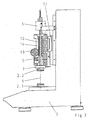
- the apparatus shown in the drawing is used to carry out component and material tests on samples 1, in particular of compression and tensile tests on springs and elastic components, assemblies and material samples.
- the device consists of two oppositely arranged sample receivers 2.1, 2.2, between which a force for loading between these sample holders 2.1, 2.2 arranged sample 1 can be generated.
- the lower of the two sample holders 2.1 is fixedly arranged on a base frame 3, while the other sample holder 2.2 is arranged on a movable adjusting element 4.
- a displacement sensor 5 is provided which is in communication with a displacement sensor 6.
- the upper sample holder 2.2 is in communication with a force transducer 7, which detects the force applied to the sample 1 force.
- the actuator 4 has in the embodiment of the Fig. 1 and 2 a standing with the sample holder 2.2, hollow-drilled spindle 8, which surrounds the displacement sensor 5 with a small distance.
- the manual or motor force application takes place, which takes place here also in consequence of the small distance to the measuring axis 9 coaxially.
- the spindle 8 itself is - as is clear from the Fig. 2 can be seen - attached via a spindle nut 10 in the adjusting element 4 and rotationally driven via a motor 15 via a gear 16.
- the actuator 4, as well as the FIG. 2 can recognize, connected via a play-free guide 11 on the base frame 3.
- FIGS. 3 to 5 show, instead of the spindle 8, a toothed rack provided with a toothing 12 extending in the axial direction can be used.
- this toothing 12 engages a pinion 13, via which the force is introduced into the rack 8.
- This can either - as indicated in the drawing - done by hand or be made by electric motor. Although the introduction of force is somewhat eccentric, it is still almost coaxial.
- the adjusting element 4 is in the region of the toothing, as is made Fig. 3 can be seen, provided with a recess 14 for the passage of the pinion 13.
- the toothing 12 can be introduced into the cylindrical lateral surface of the toothed rack 8, wherein the pinion 13 can have a shape adapted to the surface of the toothed rack 8 for this purpose.
- the rack 8 is provided, at least in the region of the toothing 12, with an axially extending free-cutting, whereby the toothed rack 8 forms a half-shell which only half encompasses the position sensor 5.
- both cut surfaces of the rack 8 are provided with a toothing 12, wherein the cut surfaces approximately in the plane of educaach lie, so that here the force is applied on both sides of the strigfach, but directly in the plane.
- each of the two gearing engages each arranged on a common shaft pinion, whereby the resulting force falls into the scholarachse.
- a pinion with a radial groove it is also possible to use instead a pinion with a radial groove.
Landscapes
- Physics & Mathematics (AREA)
- Health & Medical Sciences (AREA)
- Life Sciences & Earth Sciences (AREA)
- Chemical & Material Sciences (AREA)
- Analytical Chemistry (AREA)
- Biochemistry (AREA)
- General Health & Medical Sciences (AREA)
- General Physics & Mathematics (AREA)
- Immunology (AREA)
- Pathology (AREA)
- Investigating Strength Of Materials By Application Of Mechanical Stress (AREA)
- Transmission Devices (AREA)
Claims (7)
- Dispositif permettant de réaliser des contrôles d'éléments constitutifs et de matériaux sur des échantillons, en particulier des essais de compression et de traction sur des ressorts et des éléments constitutifs, des modules et des échantillons de matériaux élastiques, avec deux logements d'échantillon (2.1, 2.2) disposés l'un en face de l'autre, entre lesquels il est possible de produire une force pour la mise en charge de l'échantillon (1) disposé entre eux, dans lequel un premier logement d'échantillon (2.1) est fixé sur un bâti de base (3) et l'autre logement d'échantillon (2.2) est disposé sur un élément de réglage déplaçable (4), avec en outre un enregistreur de course (6) détectant le chemin parcouru par le logement d'échantillon (2.2) au moyen d'un palpeur de course (5), ainsi qu'avec un enregistreur de force (7) détectant la force appliquée à l'échantillon (1), caractérisé en ce que l'élément de réglage (4) présente un élément d'introduction de force (8) percé axialement, entourant le palpeur de course (5) à faible distance et se trouvant en liaison avec le logement d'échantillon (2.2), qui est réalisé sous la forme d'une broche, d'une crémaillère, d'un cylindre hydraulique ou pneumatique ou analogue, par lequel l'introduction manuelle ou motorisée de force est effectuée coaxialement ou au moins à peu près coaxialement à l'axe d'essai (9).
- Dispositif selon la revendication 1, caractérisé en ce que, dans le cas d'un élément d'introduction de force (8) réalisé sous la forme d'une broche, celle-ci est fixée dans l'élément de réglage (4) au moyen d'un écrou de broche (10).
- Dispositif selon la revendication 1 ou 2, caractérisé en ce que l'élément de réglage (4) est relié au bâti de base (3) au moyen d'une glissière sans jeu (11).
- Dispositif selon l'une quelconque des revendications 1 à 3, caractérisé en ce que, dans le cas où l'élément d'introduction de force (8) est réalisé sous la forme d'une crémaillère avec une denture (12) s'étendant en direction axiale, l'introduction de force est effectuée au moyen d'un pignon (13).
- Dispositif selon la revendication 4, caractérisé en ce que l'élément de réglage (4) est muni, dans la région de la denture (12), d'une découpe (14) pour le passage du pignon (13).
- Dispositif selon la revendication 4 ou 5, caractérisé en ce que la denture (12) est taillée dans la surface latérale cylindrique de la crémaillère (8).
- Dispositif selon la revendication 4 ou 5, caractérisé en ce que la crémaillère (8) est munie, au moins dans la région de la denture (12), d'une découpe libre s'étendant axialement, par laquelle une demi-coquille n'entourant qu'à moitié le palpeur de course (5) est formée, dans lequel les deux faces de coupe sont munies d'une denture (12) et un pignon (13) monté sur un arbre commun engrène respectivement avec chaque denture (12).
Applications Claiming Priority (2)
| Application Number | Priority Date | Filing Date | Title |
|---|---|---|---|
| DE102009036247A DE102009036247A1 (de) | 2009-08-05 | 2009-08-05 | Vorrichtung zur Durchführung von Bauteil- und Werkstoffprüfungen an Proben |
| PCT/DE2010/000681 WO2011015171A2 (fr) | 2009-08-05 | 2010-06-17 | Dispositif permettant de réaliser des contrôles d'éléments constitutifs ou de matériaux sur des échantillons |
Publications (2)
| Publication Number | Publication Date |
|---|---|
| EP2462422A2 EP2462422A2 (fr) | 2012-06-13 |
| EP2462422B1 true EP2462422B1 (fr) | 2013-10-09 |
Family
ID=43430100
Family Applications (1)
| Application Number | Title | Priority Date | Filing Date |
|---|---|---|---|
| EP10739472.8A Not-in-force EP2462422B1 (fr) | 2009-08-05 | 2010-06-17 | Dispositif permettant de réaliser des contrôles d'éléments constitutifs ou de matériaux sur des échantillons |
Country Status (4)
| Country | Link |
|---|---|
| US (1) | US20120192655A1 (fr) |
| EP (1) | EP2462422B1 (fr) |
| DE (1) | DE102009036247A1 (fr) |
| WO (1) | WO2011015171A2 (fr) |
Families Citing this family (8)
| Publication number | Priority date | Publication date | Assignee | Title |
|---|---|---|---|---|
| US9378662B2 (en) * | 2011-08-04 | 2016-06-28 | Ats Holdings Llc | Simplified spine testing device |
| CN103398898A (zh) * | 2013-08-16 | 2013-11-20 | 常熟市苏常工程质量检测有限公司 | 一种抗压力测试设备 |
| DE102015201993A1 (de) | 2015-02-05 | 2016-08-11 | Zwick Gmbh & Co. Kg | Materialprobenhalter mit Ansteuereinheit |
| CN104749031B (zh) * | 2015-04-13 | 2017-05-17 | 武汉理工大学 | 旋转叶片测量夹具及测量方法 |
| CN109827839B (zh) * | 2019-02-14 | 2021-02-09 | 南京航空航天大学 | 陶瓷基复合材料内部纱线力学性能测试装置及测试方法 |
| CN112577892B (zh) * | 2020-12-11 | 2024-03-12 | 中国汽车工程研究院股份有限公司 | 材料摩擦异响试验台齿轮齿条式加载压杆 |
| CN113701969B (zh) * | 2021-10-27 | 2022-02-11 | 海安东洋弹簧有限公司 | 一种钻杆弹簧压缩性能检测设备 |
| CN120467857B (zh) * | 2025-05-26 | 2026-03-10 | 中国矿业大学 | 锚杆或锚索应力实时监测装置及围岩稳定性评估方法 |
Family Cites Families (4)
| Publication number | Priority date | Publication date | Assignee | Title |
|---|---|---|---|---|
| JPH05149851A (ja) * | 1991-11-29 | 1993-06-15 | Toshin Kogyo Kk | 材料試験機 |
| US6539809B1 (en) * | 1999-04-18 | 2003-04-01 | Testing Machines, Inc. | Test apparatus for measuring stresses and strains |
| ATE390625T1 (de) * | 2000-02-03 | 2008-04-15 | Mettler Toledo Ag | Vorrichtung zur dynamischen mechanischen analyse von proben |
| AU2001265372B2 (en) * | 2000-06-06 | 2005-07-07 | Mts Systems Corporation | Statistically rigid and dynamically compliant material testing system |
-
2009
- 2009-08-05 DE DE102009036247A patent/DE102009036247A1/de not_active Withdrawn
-
2010
- 2010-06-17 US US13/387,145 patent/US20120192655A1/en not_active Abandoned
- 2010-06-17 WO PCT/DE2010/000681 patent/WO2011015171A2/fr not_active Ceased
- 2010-06-17 EP EP10739472.8A patent/EP2462422B1/fr not_active Not-in-force
Also Published As
| Publication number | Publication date |
|---|---|
| DE102009036247A1 (de) | 2011-02-10 |
| EP2462422A2 (fr) | 2012-06-13 |
| WO2011015171A2 (fr) | 2011-02-10 |
| US20120192655A1 (en) | 2012-08-02 |
| WO2011015171A3 (fr) | 2011-12-29 |
Similar Documents
| Publication | Publication Date | Title |
|---|---|---|
| EP2462422B1 (fr) | Dispositif permettant de réaliser des contrôles d'éléments constitutifs ou de matériaux sur des échantillons | |
| DE102008050465B4 (de) | Vorrichtung zur Durchführung von Bauteil- und Werkstoffprüfungen an Proben | |
| DE102013007535B3 (de) | Kraft-Messvorrichtung | |
| DE102014200703A1 (de) | Testeinrichtung für flächige Materialien und Testverfahren | |
| DE9014783U1 (de) | Motorgetriebene Presse mit Kraft- und Wegsensoren | |
| EP1980835A1 (fr) | Dispositif pour mesurer la rigidité de flexion | |
| WO2011015170A2 (fr) | Dispositif pour la réalisation d'essais de composants et de matériaux sur des échantillons | |
| EP1126269B1 (fr) | Dispositif pour l'analyse mécanique dynamique d'échantillons | |
| DE2753549C2 (de) | Überlastsicherung für eine Kraftmeßeinrichtung | |
| DE3128537C2 (fr) | ||
| DE3623362C2 (fr) | ||
| WO2003060481A1 (fr) | Dispositif de mesure de force a faible taux de vibrations dans des essais de traction dynamiques rapides sur des echantillons de materiaux | |
| DE4327260C2 (de) | Manuell zu betätigender Härteprüfer | |
| DE102016123122B3 (de) | Haptic-Test-Messvorrichtung und Verfahren zur Ermittlung einer Kraft-Weg-Kurve bei einer Haptic-Test-Messung | |
| DE19751377A1 (de) | Prüfvorrichtung | |
| DE102014107127A1 (de) | Pulverpresse | |
| DE102013003691B4 (de) | Belastungsmaschine | |
| DE20314761U1 (de) | Vorrichtung zur mechanischen Werkstoffprüfung | |
| DE19517215C1 (de) | Mehrkoordinaten-Tastkopf | |
| EP2863172A1 (fr) | Dispositif et procédé destinés à la mesure non destructrice de l'épaisseur de couche d'une mousse en matière synthétique dans un matériau comprenant couche de mousse en matière synthétique disposée sur une couche de peau est accessible au moins sur une section depuis au moins un côté | |
| DE20020909U1 (de) | Vorrichtung zur Durchführung von kraftgesteuerten Ermüdungsversuchen an dünnen Proben | |
| DE2707873C2 (de) | Härteprüfer nach Rockwell | |
| DE19531640C2 (de) | Vorrichtung zur Ermittlung der Bruchfestigkeit von Holz | |
| DE914071C (de) | Verfahren und Vorrichtung zur Bestimmung der Haerte eines Werkstoffes | |
| DE2750461A1 (de) | Wegaufnehmer |
Legal Events
| Date | Code | Title | Description |
|---|---|---|---|
| PUAI | Public reference made under article 153(3) epc to a published international application that has entered the european phase |
Free format text: ORIGINAL CODE: 0009012 |
|
| 17P | Request for examination filed |
Effective date: 20120131 |
|
| AK | Designated contracting states |
Kind code of ref document: A2 Designated state(s): AL AT BE BG CH CY CZ DE DK EE ES FI FR GB GR HR HU IE IS IT LI LT LU LV MC MK MT NL NO PL PT RO SE SI SK SM TR |
|
| DAX | Request for extension of the european patent (deleted) | ||
| 17Q | First examination report despatched |
Effective date: 20121213 |
|
| REG | Reference to a national code |
Ref country code: DE Ref legal event code: R079 Ref document number: 502010005019 Country of ref document: DE Free format text: PREVIOUS MAIN CLASS: G01N0003020000 Ipc: G01N0003040000 |
|
| RIC1 | Information provided on ipc code assigned before grant |
Ipc: G01N 3/04 20060101AFI20130423BHEP |
|
| GRAP | Despatch of communication of intention to grant a patent |
Free format text: ORIGINAL CODE: EPIDOSNIGR1 |
|
| INTG | Intention to grant announced |
Effective date: 20130605 |
|
| GRAS | Grant fee paid |
Free format text: ORIGINAL CODE: EPIDOSNIGR3 |
|
| GRAA | (expected) grant |
Free format text: ORIGINAL CODE: 0009210 |
|
| AK | Designated contracting states |
Kind code of ref document: B1 Designated state(s): AL AT BE BG CH CY CZ DE DK EE ES FI FR GB GR HR HU IE IS IT LI LT LU LV MC MK MT NL NO PL PT RO SE SI SK SM TR |
|
| REG | Reference to a national code |
Ref country code: GB Ref legal event code: FG4D Free format text: NOT ENGLISH |
|
| REG | Reference to a national code |
Ref country code: AT Ref legal event code: REF Ref document number: 635764 Country of ref document: AT Kind code of ref document: T Effective date: 20131015 Ref country code: CH Ref legal event code: EP Ref country code: CH Ref legal event code: NV Representative=s name: ISLER AND PEDRAZZINI AG, CH |
|
| REG | Reference to a national code |
Ref country code: IE Ref legal event code: FG4D Free format text: LANGUAGE OF EP DOCUMENT: GERMAN |
|
| REG | Reference to a national code |
Ref country code: DE Ref legal event code: R096 Ref document number: 502010005019 Country of ref document: DE Effective date: 20131205 |
|
| REG | Reference to a national code |
Ref country code: NL Ref legal event code: VDEP Effective date: 20131009 |
|
| PG25 | Lapsed in a contracting state [announced via postgrant information from national office to epo] |
Ref country code: SI Free format text: LAPSE BECAUSE OF FAILURE TO SUBMIT A TRANSLATION OF THE DESCRIPTION OR TO PAY THE FEE WITHIN THE PRESCRIBED TIME-LIMIT Effective date: 20131009 |
|
| REG | Reference to a national code |
Ref country code: LT Ref legal event code: MG4D |
|
| PG25 | Lapsed in a contracting state [announced via postgrant information from national office to epo] |
Ref country code: NL Free format text: LAPSE BECAUSE OF FAILURE TO SUBMIT A TRANSLATION OF THE DESCRIPTION OR TO PAY THE FEE WITHIN THE PRESCRIBED TIME-LIMIT Effective date: 20131009 Ref country code: HR Free format text: LAPSE BECAUSE OF FAILURE TO SUBMIT A TRANSLATION OF THE DESCRIPTION OR TO PAY THE FEE WITHIN THE PRESCRIBED TIME-LIMIT Effective date: 20131009 Ref country code: LT Free format text: LAPSE BECAUSE OF FAILURE TO SUBMIT A TRANSLATION OF THE DESCRIPTION OR TO PAY THE FEE WITHIN THE PRESCRIBED TIME-LIMIT Effective date: 20131009 Ref country code: SE Free format text: LAPSE BECAUSE OF FAILURE TO SUBMIT A TRANSLATION OF THE DESCRIPTION OR TO PAY THE FEE WITHIN THE PRESCRIBED TIME-LIMIT Effective date: 20131009 Ref country code: FI Free format text: LAPSE BECAUSE OF FAILURE TO SUBMIT A TRANSLATION OF THE DESCRIPTION OR TO PAY THE FEE WITHIN THE PRESCRIBED TIME-LIMIT Effective date: 20131009 Ref country code: IS Free format text: LAPSE BECAUSE OF FAILURE TO SUBMIT A TRANSLATION OF THE DESCRIPTION OR TO PAY THE FEE WITHIN THE PRESCRIBED TIME-LIMIT Effective date: 20140209 Ref country code: NO Free format text: LAPSE BECAUSE OF FAILURE TO SUBMIT A TRANSLATION OF THE DESCRIPTION OR TO PAY THE FEE WITHIN THE PRESCRIBED TIME-LIMIT Effective date: 20140109 |
|
| PG25 | Lapsed in a contracting state [announced via postgrant information from national office to epo] |
Ref country code: CY Free format text: LAPSE BECAUSE OF FAILURE TO SUBMIT A TRANSLATION OF THE DESCRIPTION OR TO PAY THE FEE WITHIN THE PRESCRIBED TIME-LIMIT Effective date: 20131009 Ref country code: ES Free format text: LAPSE BECAUSE OF FAILURE TO SUBMIT A TRANSLATION OF THE DESCRIPTION OR TO PAY THE FEE WITHIN THE PRESCRIBED TIME-LIMIT Effective date: 20131009 Ref country code: LV Free format text: LAPSE BECAUSE OF FAILURE TO SUBMIT A TRANSLATION OF THE DESCRIPTION OR TO PAY THE FEE WITHIN THE PRESCRIBED TIME-LIMIT Effective date: 20131009 Ref country code: PL Free format text: LAPSE BECAUSE OF FAILURE TO SUBMIT A TRANSLATION OF THE DESCRIPTION OR TO PAY THE FEE WITHIN THE PRESCRIBED TIME-LIMIT Effective date: 20131009 |
|
| PG25 | Lapsed in a contracting state [announced via postgrant information from national office to epo] |
Ref country code: PT Free format text: LAPSE BECAUSE OF FAILURE TO SUBMIT A TRANSLATION OF THE DESCRIPTION OR TO PAY THE FEE WITHIN THE PRESCRIBED TIME-LIMIT Effective date: 20140210 |
|
| REG | Reference to a national code |
Ref country code: DE Ref legal event code: R097 Ref document number: 502010005019 Country of ref document: DE |
|
| PG25 | Lapsed in a contracting state [announced via postgrant information from national office to epo] |
Ref country code: EE Free format text: LAPSE BECAUSE OF FAILURE TO SUBMIT A TRANSLATION OF THE DESCRIPTION OR TO PAY THE FEE WITHIN THE PRESCRIBED TIME-LIMIT Effective date: 20131009 |
|
| PLBE | No opposition filed within time limit |
Free format text: ORIGINAL CODE: 0009261 |
|
| STAA | Information on the status of an ep patent application or granted ep patent |
Free format text: STATUS: NO OPPOSITION FILED WITHIN TIME LIMIT |
|
| PG25 | Lapsed in a contracting state [announced via postgrant information from national office to epo] |
Ref country code: CZ Free format text: LAPSE BECAUSE OF FAILURE TO SUBMIT A TRANSLATION OF THE DESCRIPTION OR TO PAY THE FEE WITHIN THE PRESCRIBED TIME-LIMIT Effective date: 20131009 Ref country code: SK Free format text: LAPSE BECAUSE OF FAILURE TO SUBMIT A TRANSLATION OF THE DESCRIPTION OR TO PAY THE FEE WITHIN THE PRESCRIBED TIME-LIMIT Effective date: 20131009 Ref country code: RO Free format text: LAPSE BECAUSE OF FAILURE TO SUBMIT A TRANSLATION OF THE DESCRIPTION OR TO PAY THE FEE WITHIN THE PRESCRIBED TIME-LIMIT Effective date: 20131009 Ref country code: IT Free format text: LAPSE BECAUSE OF FAILURE TO SUBMIT A TRANSLATION OF THE DESCRIPTION OR TO PAY THE FEE WITHIN THE PRESCRIBED TIME-LIMIT Effective date: 20131009 |
|
| 26N | No opposition filed |
Effective date: 20140710 |
|
| PG25 | Lapsed in a contracting state [announced via postgrant information from national office to epo] |
Ref country code: DK Free format text: LAPSE BECAUSE OF FAILURE TO SUBMIT A TRANSLATION OF THE DESCRIPTION OR TO PAY THE FEE WITHIN THE PRESCRIBED TIME-LIMIT Effective date: 20131009 |
|
| REG | Reference to a national code |
Ref country code: DE Ref legal event code: R097 Ref document number: 502010005019 Country of ref document: DE Effective date: 20140710 |
|
| PG25 | Lapsed in a contracting state [announced via postgrant information from national office to epo] |
Ref country code: MC Free format text: LAPSE BECAUSE OF FAILURE TO SUBMIT A TRANSLATION OF THE DESCRIPTION OR TO PAY THE FEE WITHIN THE PRESCRIBED TIME-LIMIT Effective date: 20131009 Ref country code: LU Free format text: LAPSE BECAUSE OF FAILURE TO SUBMIT A TRANSLATION OF THE DESCRIPTION OR TO PAY THE FEE WITHIN THE PRESCRIBED TIME-LIMIT Effective date: 20140617 |
|
| REG | Reference to a national code |
Ref country code: IE Ref legal event code: MM4A |
|
| PG25 | Lapsed in a contracting state [announced via postgrant information from national office to epo] |
Ref country code: IE Free format text: LAPSE BECAUSE OF NON-PAYMENT OF DUE FEES Effective date: 20140617 |
|
| REG | Reference to a national code |
Ref country code: FR Ref legal event code: PLFP Year of fee payment: 7 |
|
| PG25 | Lapsed in a contracting state [announced via postgrant information from national office to epo] |
Ref country code: MT Free format text: LAPSE BECAUSE OF FAILURE TO SUBMIT A TRANSLATION OF THE DESCRIPTION OR TO PAY THE FEE WITHIN THE PRESCRIBED TIME-LIMIT Effective date: 20131009 |
|
| PG25 | Lapsed in a contracting state [announced via postgrant information from national office to epo] |
Ref country code: SM Free format text: LAPSE BECAUSE OF FAILURE TO SUBMIT A TRANSLATION OF THE DESCRIPTION OR TO PAY THE FEE WITHIN THE PRESCRIBED TIME-LIMIT Effective date: 20131009 |
|
| PG25 | Lapsed in a contracting state [announced via postgrant information from national office to epo] |
Ref country code: GR Free format text: LAPSE BECAUSE OF FAILURE TO SUBMIT A TRANSLATION OF THE DESCRIPTION OR TO PAY THE FEE WITHIN THE PRESCRIBED TIME-LIMIT Effective date: 20140110 Ref country code: BG Free format text: LAPSE BECAUSE OF FAILURE TO SUBMIT A TRANSLATION OF THE DESCRIPTION OR TO PAY THE FEE WITHIN THE PRESCRIBED TIME-LIMIT Effective date: 20131009 |
|
| PG25 | Lapsed in a contracting state [announced via postgrant information from national office to epo] |
Ref country code: HU Free format text: LAPSE BECAUSE OF FAILURE TO SUBMIT A TRANSLATION OF THE DESCRIPTION OR TO PAY THE FEE WITHIN THE PRESCRIBED TIME-LIMIT; INVALID AB INITIO Effective date: 20100617 Ref country code: TR Free format text: LAPSE BECAUSE OF FAILURE TO SUBMIT A TRANSLATION OF THE DESCRIPTION OR TO PAY THE FEE WITHIN THE PRESCRIBED TIME-LIMIT Effective date: 20131009 |
|
| REG | Reference to a national code |
Ref country code: FR Ref legal event code: PLFP Year of fee payment: 8 |
|
| REG | Reference to a national code |
Ref country code: FR Ref legal event code: PLFP Year of fee payment: 9 |
|
| PG25 | Lapsed in a contracting state [announced via postgrant information from national office to epo] |
Ref country code: MK Free format text: LAPSE BECAUSE OF FAILURE TO SUBMIT A TRANSLATION OF THE DESCRIPTION OR TO PAY THE FEE WITHIN THE PRESCRIBED TIME-LIMIT Effective date: 20131009 |
|
| PG25 | Lapsed in a contracting state [announced via postgrant information from national office to epo] |
Ref country code: AL Free format text: LAPSE BECAUSE OF FAILURE TO SUBMIT A TRANSLATION OF THE DESCRIPTION OR TO PAY THE FEE WITHIN THE PRESCRIBED TIME-LIMIT Effective date: 20131009 |
|
| PGFP | Annual fee paid to national office [announced via postgrant information from national office to epo] |
Ref country code: BE Payment date: 20190527 Year of fee payment: 10 Ref country code: FR Payment date: 20190410 Year of fee payment: 10 |
|
| PGFP | Annual fee paid to national office [announced via postgrant information from national office to epo] |
Ref country code: CH Payment date: 20190611 Year of fee payment: 10 |
|
| PGFP | Annual fee paid to national office [announced via postgrant information from national office to epo] |
Ref country code: GB Payment date: 20190624 Year of fee payment: 10 Ref country code: AT Payment date: 20190607 Year of fee payment: 10 Ref country code: DE Payment date: 20190816 Year of fee payment: 10 |
|
| REG | Reference to a national code |
Ref country code: DE Ref legal event code: R119 Ref document number: 502010005019 Country of ref document: DE |
|
| REG | Reference to a national code |
Ref country code: CH Ref legal event code: PL |
|
| REG | Reference to a national code |
Ref country code: AT Ref legal event code: MM01 Ref document number: 635764 Country of ref document: AT Kind code of ref document: T Effective date: 20200617 |
|
| GBPC | Gb: european patent ceased through non-payment of renewal fee |
Effective date: 20200617 |
|
| REG | Reference to a national code |
Ref country code: BE Ref legal event code: MM Effective date: 20200630 |
|
| PG25 | Lapsed in a contracting state [announced via postgrant information from national office to epo] |
Ref country code: FR Free format text: LAPSE BECAUSE OF NON-PAYMENT OF DUE FEES Effective date: 20200630 Ref country code: GB Free format text: LAPSE BECAUSE OF NON-PAYMENT OF DUE FEES Effective date: 20200617 Ref country code: LI Free format text: LAPSE BECAUSE OF NON-PAYMENT OF DUE FEES Effective date: 20200630 Ref country code: CH Free format text: LAPSE BECAUSE OF NON-PAYMENT OF DUE FEES Effective date: 20200630 |
|
| PG25 | Lapsed in a contracting state [announced via postgrant information from national office to epo] |
Ref country code: AT Free format text: LAPSE BECAUSE OF NON-PAYMENT OF DUE FEES Effective date: 20200617 Ref country code: BE Free format text: LAPSE BECAUSE OF NON-PAYMENT OF DUE FEES Effective date: 20200630 Ref country code: DE Free format text: LAPSE BECAUSE OF NON-PAYMENT OF DUE FEES Effective date: 20210101 |