EP2464072B1 - Frequenzwiederverwendung in drahtlosen Punkt-zu-Punkt-Kommunikationssystemen - Google Patents
Frequenzwiederverwendung in drahtlosen Punkt-zu-Punkt-Kommunikationssystemen Download PDFInfo
- Publication number
- EP2464072B1 EP2464072B1 EP10194038.5A EP10194038A EP2464072B1 EP 2464072 B1 EP2464072 B1 EP 2464072B1 EP 10194038 A EP10194038 A EP 10194038A EP 2464072 B1 EP2464072 B1 EP 2464072B1
- Authority
- EP
- European Patent Office
- Prior art keywords
- signal
- communication signal
- site
- communication
- modified
- Prior art date
- Legal status (The legal status is an assumption and is not a legal conclusion. Google has not performed a legal analysis and makes no representation as to the accuracy of the status listed.)
- Active
Links
Images


Classifications
-
- H—ELECTRICITY
- H04—ELECTRIC COMMUNICATION TECHNIQUE
- H04L—TRANSMISSION OF DIGITAL INFORMATION, e.g. TELEGRAPHIC COMMUNICATION
- H04L27/00—Modulated-carrier systems
- H04L27/32—Carrier systems characterised by combinations of two or more of the types covered by groups H04L27/02, H04L27/10, H04L27/18 or H04L27/26
- H04L27/34—Amplitude- and phase-modulated carrier systems, e.g. quadrature-amplitude modulated carrier systems
- H04L27/36—Modulator circuits; Transmitter circuits
- H04L27/366—Arrangements for compensating undesirable properties of the transmission path between the modulator and the demodulator
-
- H—ELECTRICITY
- H04—ELECTRIC COMMUNICATION TECHNIQUE
- H04B—TRANSMISSION
- H04B7/00—Radio transmission systems, i.e. using radiation field
- H04B7/02—Diversity systems; Multi-antenna system, i.e. transmission or reception using multiple antennas
- H04B7/04—Diversity systems; Multi-antenna system, i.e. transmission or reception using multiple antennas using two or more spaced independent antennas
- H04B7/0413—MIMO systems
-
- H—ELECTRICITY
- H04—ELECTRIC COMMUNICATION TECHNIQUE
- H04L—TRANSMISSION OF DIGITAL INFORMATION, e.g. TELEGRAPHIC COMMUNICATION
- H04L25/00—Baseband systems
- H04L25/02—Details ; arrangements for supplying electrical power along data transmission lines
- H04L25/03—Shaping networks in transmitter or receiver, e.g. adaptive shaping networks
- H04L25/03006—Arrangements for removing intersymbol interference
- H04L25/03343—Arrangements at the transmitter end
-
- H—ELECTRICITY
- H04—ELECTRIC COMMUNICATION TECHNIQUE
- H04B—TRANSMISSION
- H04B7/00—Radio transmission systems, i.e. using radiation field
- H04B7/02—Diversity systems; Multi-antenna system, i.e. transmission or reception using multiple antennas
- H04B7/04—Diversity systems; Multi-antenna system, i.e. transmission or reception using multiple antennas using two or more spaced independent antennas
- H04B7/06—Diversity systems; Multi-antenna system, i.e. transmission or reception using multiple antennas using two or more spaced independent antennas at the transmitting station
- H04B7/0613—Diversity systems; Multi-antenna system, i.e. transmission or reception using multiple antennas using two or more spaced independent antennas at the transmitting station using simultaneous transmission
- H04B7/0667—Diversity systems; Multi-antenna system, i.e. transmission or reception using multiple antennas using two or more spaced independent antennas at the transmitting station using simultaneous transmission of delayed versions of same signal
- H04B7/0671—Diversity systems; Multi-antenna system, i.e. transmission or reception using multiple antennas using two or more spaced independent antennas at the transmitting station using simultaneous transmission of delayed versions of same signal using different delays between antennas
Definitions
- the present invention in some embodiments thereof, relates to a wireless point-to-point communication system, and, more particularly, but not exclusively, to a single-carrier modulation scheme with a continuous transmission.
- Wireless point-to-point communication systems are deployed all over the world, for example as a backbone of cellular networks and wireless Internet services.
- the wireless point-to-point communication systems usually require a Line-Of-Sight (LOS) and use a regulated frequency band, in order to ensure high availability with little or no interference.
- a required bit-error-rate in such links is typically below 10 -13 .
- Frequency bands used in such regulated communication systems are commonly in the range of 7 GHz to 38 GHz .
- transmission beams are generated using dish antennas which focus the transmission beams, which provide a receiver with a stronger signal and less interference than unfocused transmissions.
- the focused beams cause interference with other wireless links which use the same frequency when the beams are also in a similar direction.
- Figure 1A is a simplified illustration of a tree network 100 scenario in which an aggregation point 110 communicates with two tail sites 115 116 via two communication links 113 114.
- Such a scenario is termed a tree network, in which the tail sites 115 116 are tree "leaves".
- An angular separation 111 between the two tail sites 115 116 is too small for using the same frequency on the two communication links 113 114.
- the interference between the two communication links 113 114 is in both directions, i.e., from the aggregation point 110 to the tail sites 115 116 and from the tail sites 115 116 to the aggregation point 110.
- Frequencies are usually regulated, and obtaining frequencies is very expensive. If no communication frequencies are available, wireless communication cannot be established, and expensive alternatives should be considered, such as, by way of a non-limiting example, laying a land line.
- FIG. 1B is a simplified illustration of a ring network 120 scenario in which the ring network includes several nodes 125 126 127 128 129.
- the nodes 125 126 127 128 129 are connected by communication links 140 141 142 143 144.
- Angular separations 130, 132, and 133 between the communication links 140 144, 141 142, and 142 143 respectively, are too small for using a same frequency on the pairs of communication links 140 144, 141 142, and 142 143 respectively.
- Angular separations 131 and 134 between the communication links 140 141 and 143 144 respectively are close to 180°. At such angles if a same frequency is used on the pairs of communication links, the pairs of communication links 140 141 and 143 144 may interfere. For example, node A 125 may receive both communications via the communication link 140 from node B 126 and interference from the communication link 141 from node C 127.
- Figure 1B depicts a ring with all communication links having potentially problematic angles. Many rings may have some communication links with problematic angles, and some without.
- both the ring network 120 and the tree network 100 with an aggregation point are common scenarios.
- Miao Lu Bo Chen, Xiaolin Hou, Xin Zhang, Dongmei Luo, "A Data Aided Channel Estimation Method Based on CAZAC", IEEE 68th Vehicular Technology Conference, 2008, pp.1 - 5 .
- the present invention in some embodiments thereof, includes a method for interference reduction in accordance with claim 1 and an apparatus for interference reduction in accordance with claim 6.
- Interference between two communication beams from a single aggregation point is affected by the contents of the two communication beams.
- the contents of the two communication channels are known at the aggregation point. Therefore something is optionally done at the aggregation point about the interference, based on knowing the contents.
- aggregation point in all its grammatical forms is used throughout the present specification and claims to mean a location from which two or more communication channels are transmitted.
- the communication links which according to prior art had to use different frequencies, may use the same frequency.
- Using the same frequency also termed frequency re-use, may save significant expense if the alternative was buying an additional frequency, or significant expense and effort, if laying a land line was the alternative.
- the tree-network-with-an-aggregation-point scenario described in the Background section, will be used to demonstrate various features, for purpose of simplifying the description.
- the invention applies to the ring network scenario as well, and to other scenarios in which a node receives and transmits in directions which have a small angular separation.
- What actual angle may be considered to form a small angular separation may depend on desired Signal to Noise Ratio (SNR) at a receiver, and/or on a desired Bit Error Rate (BER).
- SNR Signal to Noise Ratio
- BER Bit Error Rate
- a 16-QAM modulation with an example coding may provide an acceptable BER of 10 -12 at an SNR of 20 dB. If interference is to degrade performance by no more than 0.5 dB, the interference should be at least 10 dB below thermal noise, about 30 dB below a required signal level.
- a desired angular separation depends on an antenna size and carrier frequency, as shown in the following example table.
- the angular separation in the example ranges between 5 degrees and 17.5 degrees.
- Table 1 Carrier frequency ⁇ 15 18 23 28 38 Antenna diameter GHz GHz GHz GHz GHz GHz 1[Ft] 17.5 15.0 12.0 9.0 2[ft] 9.0 9.0 10.0 4.5 5.0
- the required angular separation may reach angles of 60 degrees and more. Sometimes no separation is good enough.
- embodiments of the invention are especially useful, enabling a cancelling of interference at a transmitting end, thereby enabling frequency reuse.
- the present invention in some embodiments thereof, presents a practical method for sharing, or reusing, the same frequency in two previously interfering communication channels, by substantially reducing the interference.
- the aggregation point can transmit to the two tail sites in the same frequency and receive signals from both tail sites in the same frequency.
- Implementation of the method and/or system of embodiments of the invention can involve performing or completing selected tasks manually, automatically, or a combination thereof. Moreover, according to actual instrumentation and equipment of embodiments of the method and/or system of the invention, several selected tasks could be implemented by hardware, by software or by firmware or by a combination thereof using an operating system.
- a data processor such as a computing platform for executing a plurality of instructions.
- the data processor includes a volatile memory for storing instructions and/or data and/or a non-volatile storage, for example, a magnetic hard-disk and/or removable media, for storing instructions and/or data.
- a network connection is provided as well.
- a display and/or a user input device such as a keyboard or mouse are optionally provided as well.
- the present invention in some embodiments thereof, relates to a wireless point-to-point communication system, and, more particularly, but not exclusively, to a single-carrier modulation scheme with a continuous transmission.
- the tree-network-with-an-aggregation-point scenario described in the Background section, will be used to demonstrate various features, for purpose of simplifying the description.
- the invention applies to the ring network scenario as well, and to other scenarios in which a node receives and transmits in directions which have a small angular separation.
- the present invention in some embodiments thereof, describes a single-carrier modulation scheme with a continuous transmission.
- the communication channels are assumed to be dispersive and time-varying. Such conditions are common in such wireless networks.
- a unit within an aggregation point substantially decreases and/or cancels mutual interference in both directions from the aggregation point.
- the unit can optionally do so, since traffic in both directions passes through the unit.
- a pre-coder for cancelling interference between the tail sites is implemented in the aggregation site, as illustrated in Figure 2A .
- FIG. 2A is a simplified block diagram illustration of units in an aggregation point, constructed and operative according to an example embodiment of the present invention.
- An input signal for site A 203 and an input signal for site B 204 are fed into a pre-coder 205.
- the pre-coder 205 outputs a pre-coded signal for site A 208 and a pre-coded signal for site B 209.
- the pre-coded signal for site A 208 and the pre-coded signal for site B 209 are each fed into transmitter A 213 and transmitter B 214 respectively, and transmitted to site A and site B respectively.
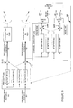
- FIG. 2B is a more detailed simplified block diagram illustration of units in an aggregation point, constructed and operative according to an example embodiment of the present invention.
- the aggregation point includes a pre-coder 235 and two transmitters 248 249.
- the pre-coder 235 is composed of 4 filters 236 237 238 239 which are configured in such a way which cancels the interference in the tail sites.
- the filters 236 237 238 239 are digital Finite Impulse Response (FIR) filters.
- An input signal for site A 233 and an input signal for site B 234 are fed into the pre-coder 235.
- the input signal for site A 233 is split in two, and fed into two of the filters 236 237 and the input signal for site B 234 is split in two, and fed into two of the filters 238 239.
- Output from two of the filters 236 238 is provided to a signal adder 241, and output from two of the filters 237 239 is provided to a signal adder 242.
- the adders 241 242 each produce a pre-coded signal for site A 243 and a pre-coded signal for site B 244.
- the pre-coded signal for site A 243 and the pre-coded signal for site B 244 are each fed into transmitter A 248 and transmitter B 249 respectively, and transmitted to site A and site B respectively.
- the output of the site A filter 237 which is added to the signal coming from the site B filter 239 is intended to cancel, as much as possible, the interference which the communication beam to site A causes to the communication beam to site B.
- the output of the site B filter 238 which is added to the signal coming from the site A filter 236 is intended to cancel, as much as possible, the interference which the communication beam to site B causes to the communication beam to site A.
- the digital FIR filters 236 237 238 239 require a method for estimating digital coefficients.
- two functions are used: a function which estimates the channel frequency response from each transmitting antenna to each receiving antenna; and a function which converts the estimates into pre-coder coefficients.
- Channel estimation may be based on transmitting a sequence known at both ends of the communication links.
- a receiver may estimate the channel by standard techniques such as, by way of a non-limiting example, techniques proposed in the references mentioned in the Background section.
- examples brought in the present application include cases with two transmission directions, to a site A and a site B.
- the descriptions of the examples are extendable to more than two transmission directions, by a person skilled in the art. Suffice it to say that more than four 236 237 238 239 filters would be used in the pre-coder 235; more than two transmitters 248 249 would be used; more than two adders 241 242 would accept signals from the more than the four filters 236 237 238 239, optionally accepting signals from each one of the transmission directions.
- FIG. 3 is a simplified illustration of four communication channels 300 301 302 303 which are to be estimated.
- Figure 3 depicts an antenna 305 for transmitting from an aggregation point 307 via the communication channel 301 to an antenna 311 at node A; an antenna 306 for transmitting from the aggregation point 307 via the communication channel 302 to an antenna 312 at node B; the communication channel 303, which stands for interfering transmissions from the antenna 305 to the antenna 312 at node B; and the communication channel 304, which stands for interfering transmissions from the antenna 306 to the antenna 311 at node B.
- each estimated channel impulse response is presented by 1 sample per symbol, 2 samples per symbol, or any other number of samples per symbol.
- the number of samples per symbol in the pre-coder filters equals the number of samples per symbol in the channel estimator. This is for convenience, since the pre-coder coefficients are derived from the channel impulse responses.
- Figure 4A is a simplified flow chart illustrating a method of calculating pre-coder coefficients, according to an example embodiment of the invention.
- the example embodiment of Figure 4A is a method for interference reduction in transmission of at least two single carrier continuous communication beams including:
- Figure 4A generally describes an embodiment of the invention at a level of detail similar to the block diagram of Figure 2A .
- Figure 4B is a simplified flow chart illustrating a method of calculating pre-coder coefficients, according to another example embodiment of the invention.
- window-coefficient W[k] For each value of k define a window-coefficient W[k] (425).
- the window coefficients may be selected using standard window functions commonly used in digital signal processing, such as a Hamming window, a Chebyshev window, and so on.
- an alternative method for obtaining the pre-coder coefficients from the channel impulse response is used, based on adaptively updating the coefficients in such a way which minimizes error, by way of a non-limiting example by minimizing a larger mean-square-error among the two remote receivers. This approach is illustrated in Figure 5 .
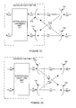
- FIG. 5 is a simplified block diagram illustration of an alternative method for obtaining pre-coder coefficients, according to an example embodiment of the invention.
- An aggregation point includes units for cancelling interference, constructed according to an example embodiment of the invention.
- the units includes a pre-coder 505 with four N-tap FIRs 510 511 512 513; two signal adders 515 516; a transmitter A 520 for transmitting to a node A, and a transmitter B 521 for transmitting to a node B.
- the pre-coder 505 has two inputs, an input signal for site A 503 and an input signal for site B 504.
- the input signal for site A 503 is split in two, and fed into two of the FIRs 510 511 and the input signal for site B 504 is split in two, and fed into two of the filters 512 513.
- Output from two of the filters 510 512 is provided to a signal adder 515, and output from two of the filters 511 513 is provided to a signal adder 516.
- the adders 515 516 each produce a pre-coded signal for site A 522 and a pre-coded signal for site B 523.
- the pre-coded signal for site A 522 and the pre-coded signal for site B 523 are each fed into transmitter A 520 and transmitter B 521 respectively, and transmitted to site A and site B respectively.
- the pre-coded signal for site A 522 and the pre-coded signal for site B 523 are also split off, and fed into a channel emulator 540.
- the channel emulator 540 optionally emulates a communication channel from transmitter A 520 to the site A, and a communication channel from transmitter B 521 to the site B, that is, optionally acts as one or more channel emulators.
- the pre-coded signal for site A 522 is split in two, and fed into two FIRs 541 542 and the pre-coded signal for site B 523 is split in two, and fed into two FIRs 543 544.
- a signal adder 548 mixes signals from the FIR 541 of the site A signal, from the FIR 543 of the site B signal, and from a noise emulator 546 of the site A channel, producing an output which emulates a communication beam to site A which includes the pre-coded signal for site A, mixed with an interfering pre-coded signal for site B, and with noise associated with the communication channel to site A.
- a signal adder 549 mixes signals from the FIR 542 of the site A signal, from the FIR 544 of the site B signal, and from a noise emulator 547 of the site B channel, producing an output which emulates a communication beam to site B, which includes the pre-coded signal for site B, mixed with an interfering pre-coded signal for site A, and with noise associated with the communication channel to site B.
- Output from the signal adders 548 549 is fed into demodulators 551 552 respectively.
- Output from the demodulators 551 552 has passed through an entire channel emulation for both the channel to site A and the channel to site B, while still at the aggregator site.
- the demodulators 551 and 552 optionally estimate a Mean Square Error (MSE 553) rate of the channel to site A and a MSE rate of the channel to site B (MSE 556).
- MSE 553 Mean Square Error
- MSE 556 MSE rate of the channel to site B
- the demodulators 551 and 552 optionally estimate a decision error rate 554 of the channel to site A and a decision error rate 557 of the channel to site B.
- the demodulators 551 and 552 estimate both the MSE rates 553 556 and the decision error rates 554 557.
- An error rate is optionally fed back to the pre-coder 505 via an optional dedicated channel 560.
- the MSE 553 is fed back.
- the MSE 556 is fed back.
- the decision error rate 554 is fed back.
- the decision error rate 557 is fed back.
- an optional error detector 559 selects which of the MSE 553 556 and the decision error rates 554 557 is to be fed back via the optional dedicated channel 560.
- the error detector 559 selects the worst error rate.
- the error detector 559 selects an error rate belonging to a site channel which a user, such as a technician, indicates as a channel for which error rates should be minimized.
- optimizing both the pre-coded signal for site A 522 and the pre-coded signal for site B 523 may involve two contradictory requirements. Both the demodulator 551 and the demodulator 552 may seek to optimize their MSE, but an optimal solution for the demodulator 551, eliminating the pre-coded signal for site B 523 completely, is bad for the pre-coded signal for site B 523.
- Figure 5 depicts an example case in which two sets of performance measures have been calculated - for a signal intended for site A and for a signal intended for site B.
- One option is to select as a performance measure a worse MSE (between the signal intended for site A and the signal intended for site B) and provide the worse MSE as feedback to the pre-coder 505.
- the pre-coder 505 optionally modifies coefficients, for example by a smart search, so as to improve the performance measure received as feedback.
- the signal intended for site A and the signal intended for site B use different modulations.
- the signal intended for site A is modulated as a 16 QAM signal
- the signal intended for site B is modulated as a 256 QAM signal.
- the signal intended for site B should have a significantly better MSE than the signal intended for site A, so the feedback signal to the pre-coder 505 would optionally consist of the MSE of the demodulator which is more "stressed", that is, the demodulator of the signal intended for site B.
- Performance is measured for A and B signals. a decision is made which signal requires improvement, and the MSE of the signal requiring improvement is optionally sent to the pre-coder 505 as feedback. MSE was mentioned above, as an example. Error rate may be used as well as other performance measures.
- a combination of performance indicators may be used as feedback, such as: a sum of error rates; a sum of mean-square-errors.
- the feedback may optionally include an actual error of each received symbol, which is useful if a Least Mean Squares (LMS) method is used for optimizing the pre-coder filter coefficients.
- LMS Least Mean Squares
- the pre-coder 505 updates FIR coefficients in order to optimize a performance measure, by way of a non-limiting example to minimize the error rate.
- the FIR coefficients are updated to minimize the error rate using, for example, a Least Mean Squares (LMS) method.
- LMS methods are a class of adaptive filter used to mimic a desired filter by finding filter coefficients that relate to producing a least mean squares of the error signal (difference between the desired and the actual signal).
- An alternative approach for evaluating the pre-coder coefficients is to feedback decision errors in the remote receivers of site A and/or of site B to the aggregation point using a dedicated channel from the remote site to the aggregation point.
- the aggregation point optionally evaluates the error rate of each receiver, and optionally selects an error rate to use in updating the pre-coder coefficients.
- channel delay when implementing the above alternative approach, channel delay also needs to be compensated for.
- the set of samples which was in the pre-coder when a symbol which resulted in a given error is known. Since the set of samples is known, coefficients are optionally updated so as to decrease the error. In some embodiments of the invention, that is how LMS is implemented.
- LMS is implemented by sending the error once every number of samples. This saves feedback bandwidth.
- the pre-coder optionally updates coefficients only when it receives an error value.
- phase shifts are obtained, for example, from a set of receivers in the aggregation site which use channel emulation similar to that described above with reference to Figure 5 , and interference error minimization similar to that described above with reference to Figure 5 , to discover appropriate phase shifts.
- Receivers of the aggregation point are described in more detail below, with reference to Figure 7B and to the section named "Cancelling Mutual Interference between Tail-Site Transmissions".
- examples brought in the present application include cases with two transmission directions, to a site A and a site B.
- the descriptions of the examples are extendable to more than two transmission directions, by a person skilled in the art. Suffice it to say that the channel emulator 540 would emulate signals for more than the two sites A and B, and/or the optional error detector 559 would select between MSE rates and/or decision error rates of more than the two sites A and B.
- the pre-coder receives feedback with mean performance measures, such as MSE and error rate, and in some embodiments the pre-coder receives feedback with actual decision errors.
- mean performance measures such as MSE and error rate
- the feedback comes from a local channel emulator plus demodulators, and in some embodiments feedback comes from actual receivers.
- the pre-coder When provided with mean performance measures, the pre-coder optionally searches for a solution which optimizes the mean performance measures.
- the search may optionally include a simple search, such as, for example: starting to shift a coefficient in one direction, if performance improves continuing in the same direction, if performance degrades, shifting the coefficient in the other direction, or stopping shifting its value and skipping to another coefficient.
- better search methods are used. For example, down-hill search using the Nelder-Mead simplex method, which is known in the art, and which performs search in a more efficient way than the above described simple search.
- the pre-coder is fed with individual decision errors.
- the pre-coder optionally inspects the data which resulted in the error.
- the pre-coder then slightly modifies the coefficients in a way which reduces the error.
- channel delay is taken into account. In order to match an error to the data in the pre-coder the delay needs to be known.
- pre-coder coefficients optionally for signals intended for both node A and node B, are modified.
- a purpose of the modification is to decrease mean error and/or individual error.
- the pre-coder when two, or more, performance measures are provided to the pre-coder, the pre-coder optionally searches for a solution in which both performance measures are better than a given requirement or some other criterion.
- FIG. 6 is a simplified block diagram of a pre-coding unit 600 constructed according to an example embodiment of the invention.
- the pre-coding unit 600 accepts inputs of an original signal for site A 603 and an original signal for site B 604.
- the pre-coding unit 605 includes two phase shifters 611 612, and two adders 613 614.
- the original signal for site A 603 is split, and part of the original signal for site A 603 is fed through a first phase shifter 611, where the phase of the original signal for site A 603 is shifted, and an output of the first phase shifter 611 is added, at a first adder 614, to the original signal for site B 604, and outputs a pre-coded signal for site B 609.
- the original signal for site B 604 is split, and part of the original signal for site B 604 is fed through a second phase shifter 612, where the phase of the original signal for site B 604 is shifted, and an output of the second phase shifter 612 is added, at a second adder 613, to the original signal for site A 603, and outputs a pre-coded signal for site A 608.
- the pre-coded signal for site B 609 and the a pre-coded signal for site A 608 are optionally fed into transmitters (not shown) for site B (not shown) and for site A (not shown), as described above with reference to Figures 2A, 2B , and 5 .
- An aggregation point optionally cancels mutual interference between two received signals using interference cancellation techniques such as, for example, interference cancellation which are used for cancelling interference between two polarizations.
- the receivers are based on adaptive equalizers. Two received signals are each passed through an equalizer. The equalizers' outputs are summed. The equalizers' coefficients are updated so as to optimize the signal at the sum output. Optimization may optionally be done with a simple decision-directed or Data-Aided LMS algorithm.
- FIG. 7A is a simplified block diagram illustration of an aggregation point 740 having a receiving interference cancelling unit 745 constructed and operational according to an example embodiment of the invention.
- the aggregation point 740 includes two antennas 741 742, each of which receives a different combination of a communication signal 746 from site A, and communication signal 747 from site B, due to mutual interference.
- the received combinations of signals 746 747 are input into the receiving interference cancelling unit 745.
- the combinations of signals 746 747 each pass through an adaptive filter 751 752.
- the adaptive filters 751 752 receive filter coefficients 765 as feedback from later in the signal flow, and coefficients of the adaptive filters 751 752 set so as to minimize decision errors.
- the adaptive filters 751 752 produce output signals 753 754 which are fed into an adder 755.
- An output signal 757 produced by the adder 755 corresponds, by way of example, to a signal 746 from the site A, with a reduced interference level.
- the output signal 757 is fed in a decision unit 760, which decides which symbol was received in the output signal 757, and produces an output signal 761, which is a decision regarding a transmitted symbol.
- the output signal 757 is also fed into a subtracting unit 762, which also receives the output signal 761 of the decision unit 760.
- the subtracting unit 762 subtracts the symbol which is the output signal 761 from the noisy output signal 757. After subtraction, a noise and interference signal 765 is left over, and produced as output of the subtracting unit 762.
- the noise and interference signal 765 is sent to an optimization unit 750.
- the optimization unit 750 produces filter coefficients 748 749 for the adaptive filters 751 752.
- the optimization unit 750 optionally updates coefficients of the adaptive filters 751 752 so as to minimize mean-square-error (MSE) of the output signal 757 of the adder 755.
- MSE mean-square-error
- the optimization unit 750 optionally updates coefficients of the adaptive filters 751 752 so as to minimize the noise and interference signal 765.
- the minimization is performed according to any one of several algorithms, such as, by way of some non-limiting examples: a least-mean-square (LMS) algorithm, a least-squares algorithm, and a recursive-least-squares algorithm.
- LMS least-mean-square
- One method of minimizing decision errors includes training the interference cancelling unit 745 with a known sequence of symbols.
- the optimization unit 750 can then use a least-mean-square (LMS) method to update coefficients of the adaptive filters 751 752 so as to minimize mean-square-error (MSE) of the output signal 757 of the adder 755.
- LMS least-mean-square
- MSE mean-square-error
- FIG. 7A optionally lessens interference from the signal 747 from site B.
- a corresponding interference cancelling is optionally constructed for the signal 747 for site B.
- Figure 7A illustrates interference cancellation with two adaptive filters 751 752, optionally equalizers.
- Bit-Error Rate (BER) is not calculated by the interference cancelling unit 740, so the example embodiment of Figure 7A does not directly optimize BER.
- an optimization criterion addresses decision errors, resulting in a minimal mean-square-decision-error, or MSE for short.
- the example embodiment of Figure 7A is good for use in an aggregation point.
- FIG. 7B is a simplified block diagram illustration of an aggregation point 700 having a receiving interference cancelling unit 710 constructed and operational according to another example embodiment of the invention.
- Figure 7B illustrates a phase shift approach to cancelling mutual interference between tail site transmissions received at an aggregation point
- the aggregation point 700 includes two antennas 712 713, receiving a communication signal 716 from site A, and a communication signal 717 from site B, respectively.
- the received signals 716 717 are input into the receiving interference cancelling unit 710.
- the signals 716 717 are split, one part of each signal going through one of two phase shifters 721 722, and another part of each signal going directly to one of two adders 723 724, which add the direct signal to phase shifted output of the phase shifters 721 722.
- Output from the adders 723 724 goes to a first demodulator 727 and a second demodulator 728.
- the first demodulator 727 demodulates a sum of the communication signal 717 from site B and a phase shifted communication signal 716 from site A
- the second modulator 728 demodulates a sum of communication signal 716 from site A and a phase shifted communication signal 717 from site B.
- the example embodiment depicted in Figure 7B includes shifting a relative phase between a portion of the two received signals 716 717 before summing to the other portion of the two received signals 716 717.
- the relative phase shift is optionally such that a first one of the signals is cancelled and a second of the signals remains.
- the phase shifting and adding of the two received signals is equivalent to nulling a signal from a direction of interference. Using a second, different phase shift, the second one of the signals is cancelled and the first of the signals remains.
- an optional mechanism for adjusting the phase shifts is based on an LMS or similar algorithm, as described above with reference to Figure 5 .
- an optional mechanism for adjusting the phase shifts scans for no interference, and/or a best MSE.
- Interference is optionally detected by searching for a correlation with a known sequence of the interfering signal.
- phase shifts obtained as described with reference to Figure 7B may optionally be used for the pre-coder of Figure 6 .
- an optional mechanism for adjusting the interference, error rate, or MSE is based on modifying the communication signal 716 from site A and the communication signal 717 from site B using an N-tap filter such as the filters 510 511 512 513 instead of phase shifting by the phase shifters 721 722.
- An optional mechanism for adjusting filter coefficient may be based on an LMS or similar algorithm, as described above with reference to Figure 5 .
- reducing interference in an aggregation point receiver enables the aggregation point to discover parameters used in reducing the interference, and use the parameters to reduce interference when transmitting from the aggregation point.
- FIG. 7C is a simplified block diagram illustration of an aggregation point 763 using an interference cancelling unit 777 for reducing received interference, constructed and operational according to another example embodiment of the invention.
- Figure 7C depicts the interference cancelling unit 777 emphasizing a leakage of interfering communication links.
- a signal 765 is broadcast via an antenna 767 from a site A, and a signal 766 is broadcast via antenna 768 from a site B.
- An antenna 773 at the aggregation point 763 receives an intended signal 769 from site A, and a leakage signal 772 from site B.
- An antenna 774 at the aggregation point 763 receives an intended signal 771 from site B, and a leakage signal 770 from site A.
- the antenna 773 passes a combined signal X1 775, which includes the intended signal 769 from site A, and the leakage signal 772 from site B.
- the antenna 774 passes a combined signal X2 776, which includes the intended signal 771 from site B, and the leakage signal 770 from site A.
- the interference cancelling unit 777 modifies the combined signal X1 775, reducing interference as much as possible, and produces an output signal A 778, which is substantially equal to the signal 765 broadcast from site A.
- the interference cancelling unit 777 modifies the combined signal X2 776, reducing interference as much as possible, and produces an output signal B 779, which is substantially equal to the signal 766 broadcast from site B.
- a 778 and B 779 from the input mixtures X1 775 and X2 776 is represented as follows:
- a B a 1 ⁇ e j ⁇ 1 b 1 ⁇ e j ⁇ 1 a 2 ⁇ e j ⁇ 2 b 1 ⁇ e j ⁇ 2 ⁇ X ⁇ 1 X ⁇ 2
- a B M ⁇ X ⁇ 1 X ⁇ 2 where M denotes the matrix in Equation 1.
- the signals X1 775 and X2 776 were received by the receiving antennas 773 774 after the signals A 765 and B 766 were transmitted. In other words, the signals A 765 and B 766 were transmitted and the communication channel caused them to mix into X1 775 and X2 776.
- Figure 7C illustrates the channel mixing, and subsequent separation.
- the interference cancelling unit 777 optionally finds a set of parameters a 1 , a 2 , b 1 , b 2 , ⁇ 1 , ⁇ 2 , ⁇ 1 , and ⁇ 2 so as to minimize interference, by way of a non-limiting example by minimizing MSE or BER, optionally as described above with reference to Figures 7A and 7B .
- the same set is optionally used for modifying one or both of the signals to the sites A and B producing pre-coded signals to the sites A and B.
- Figure 7D is a simplified block diagram illustration of the aggregation point 763 of Figure 7C , using the interference cancelling unit 770 for reducing transmission interference.
- a signal A 780, intended for a site A, is optionally fed into an interference cancelling unit 777, and a signal B 781, intended for a site B, is optionally fed into the interference cancelling unit 777.
- the interference cancelling unit 777 modifies the signals A 780 and B 781, producing output of signals X1 783 and X2 784 respectively, as will be explained below.
- the signals X1 783 and X2 784 are broadcast by antennas 773 and 774 respectively, intended for antennas 767 768 at site A and site B respectively.
- the antenna 767 at site A receives a signal 787 intended for site A and a leakage signal 790 intended for site B, combining the two signals as a combined signal 791.
- the antenna 768 at site B receives a signal 789 intended for site B and a leakage signal 788 intended for site A, combining the two signals as a combined signal 792.
- the interference cancelling unit 777 modifies the signals A 780 and B 781 so that after passing through their respective communication channels, and suffering leakage which causes interference, the received signal 791 at site A and received signal 792 at site B will be best resemble the signals A 780 and B 781.
- Figure 7D illustrates a case where roles of transmitters and receivers are switched relative to Figure 7C .
- the communication channel is often substantially reciprocal, that is, the channel modifies signals similarly when the transmitters are switched with the receivers, or when the signals pass through the communications channels in the opposite direction.
- H T matrix which is the transposed matrix of the communication channel of Figure 7C .
- Figure 8 is a simplified block diagram illustration of a setup which was used to simulate interference cancellation according to an example embodiment of the invention.
- Figure 8 The setup of Figure 8 will now be described with reference to two different cases, a first case simulating interference between two communication channels without interference cancellation according to the present invention, and a second case simulating interference between two communication channels with interference cancellation according to the present invention.
- the results of the two cases are depicted in Figure 9A and Figure 9B .
- a signal for a first site A 801 and a signal for a second site B 802 are input into a pre-coder 805.
- the pre-coder 805 is a 16 tap pre-coder, but in the case of no interference cancellation the pre-coder 805 does not change the two input signals.
- the signal for a first site A 801 and the signal for a second site B 802 are both simulated, by way of a non-limiting example, as 16 QAM signals at 50 Msps.
- embodiments of the invention may be constructed for any modulation.
- Non-limiting examples include QAM, FSK, OFDM, CPM, and so on.
- Embodiments of the invention cancel mutual interference between two or more signals interfering with each other over the air.
- channel impulse response is repeatedly estimated at successive points in time.
- Channel estimation is optionally done differently for different modulations.
- - in OFDM estimation may optionally performed directly in the frequency domain.
- the pre-coder 805 produces output of a presently unchanged signal for a first site A 806, which is split into two. One portion of the signal for the first site A 806 is fed into a notch filter 810.
- the notch filter 810 simulates an effect of multipath in a communication channel to site A. A delay of 6.3 nsec in the notch filter 810 was selected as a common standard for testing an ability of modems to cope with the multipath. A notch depth of 12 dB was selected to demonstrate performance improvement possible with embodiments of the present invention.
- Another portion of the signal for the first site A 806 is optionally fed into a gain unit 840.
- the gain of the gain unit 840 is optionally set to -20dB, producing an attenuated signal 841.
- the attenuated signal 841 may be added to a signal for site B to simulate interference for the communication channel to site B.
- the notch filter 810 produces an output 811, which is combined with a 20 dB attenuated signal for site B 836, which is output from a gain unit 835 set to provide -20 dB gain to a signal for site B 808, at an equalizer 820.
- the equalizer 820 is optionally a 24 tap equalizer.
- Adding the 20 dB attenuated signal for site B 808 simulates interference between the communication channel to site A and the communication channel to site B.
- the pre-coder 805 produces output of a presently unchanged signal for the second site B 808, which is split into two. One portion of the signal for the second site B 808 is fed into the gain unit 835 set to provide -20 dB gain, providing the output from the gain unit 835 which was used in simulating the interference of the communication channel to site B with the communication channel to site A.
- a signal quality evaluator is placed to receive output from the equalizer 820 and measure the signal quality of the simulated communication channel to site A.
- the signal quality evaluator is a MSE evaluator 850.
- Another portion of the signal for the second site B 808 is fed into a gain unit 815, which is presently set at a gain of 0 dB.
- the gain unit 815 produces an output signal 816, which is combined with the 20 dB attenuated signal for site A 841, in an antenna port (not shown) before entering equalizer 825.
- Adding the 20 dB attenuated signal for site A 841 simulates interference between the communication channel to site A and the communication channel to site B.
- the above simulation flow may be depicted as occurring in a transmitter portion 860, a channel portion 865, and a receiver portion 870.
- the setup of Figure 8 when used for simulating interference between two communication channels with interference cancellation according to the present invention is similar to the setup of Figure 8 , when used for simulating interference between two communication channels without interference, with the following differences.
- the signal for a first site A 801 and the signal for a second site B 802 are similar, and both input into the pre-coder 805.
- the pre-coder 805 does change the signal for the first site A 801 and the signal for the second site B 802
- Figure 9A is a constellation diagram 905 for rectangular 16 QAM produced as a result of simulating interference between two communication channels without interference cancellation according to the present invention.
- the constellation diagram 905 of Figure 9A includes an I-axis 906 and a Q -axis 907.
- a large number of scattered dots depict results of simulating symbols received at site A through a communication channel to site A, with interference of a communication channel to site B, through a setup as described above with reference to Figure 8 .
- the received symbols of Figure 9A are spread about their actual transmitted values due to noise in the communication channel to site A, and due to interference with the communication channel to site B.
- Figure 9A demonstrates the obtained constellation at the receiver when no pre-coding was applied. Interference limits the MSE to -20dB. Additionally, the notch on the direct channel attenuates the signal by approximately 6.5 dB. We therefore end up with an MSE of approximately 13.5 dB.
- Figure 9B is a constellation diagram 920 for rectangular 16 QAM produced as a result of simulating interference between two communication channels with interference cancellation according to the present invention.
- the constellation diagram 920 of Figure 9B includes an I-axis 926 and a Q -axis 927.
- a large number of scattered dots depict results of simulating symbols received at site A through a communication channel to site A, with interference of a communication channel to site B, through a setup as described above with reference to Figure 8 , while using interference cancellation.
- Figure 9B demonstrates the obtained constellation at the receiver when a 16-tap 2-samples-per-symbol pre-coder was applied.
- the MSE was improved to 36.6 dB.
Landscapes
- Engineering & Computer Science (AREA)
- Computer Networks & Wireless Communication (AREA)
- Signal Processing (AREA)
- Power Engineering (AREA)
- Radio Transmission System (AREA)
- Mobile Radio Communication Systems (AREA)
Claims (11)
- Verfahren zur Verringerung von Störbeeinflussungen bei der Übertragung von zumindest zwei einzelnen kontinuierlichen Trägerfrequenz-Datenübertragungsstrahlen, das umfasst:Erzeugen eines ersten Datenübertragungssignals für eine erste digitale Datenübertragungsverbindung; undErzeugen eines zweiten Datenübertragungssignals für eine zweite digitale Datenübertragungsverbindung;gekennzeichnet durch:Erzeugen eines modifizierten ersten Datenübertragungssignals durch:Erzeugen eines ersten gefilterten Signals durch Filtern des ersten Datenübertragungssignals unter Verwendung eines ersten M-Tap-Filters mit endlicher Impulsantwort (FIR-Filter) mit Koeffizienten, die für die Behebung der Senderstörbeeinflussung optimiert sind; undErzeugen eines zweiten gefilterten Signals durch Filtern des zweiten Datenübertragungssignals unter Verwendung eines zweiten M-Tap-Filters mit endlicher Impulsantwort (FIR-Filter) mit Koeffizienten, die für die Behebung der Senderstörbeeinflussung optimiert sind; undKombinieren des ersten gefilterten Signals und des zweiten gefilterten Signals;Übertragen des modifizierten ersten Datenübertragungssignals über einen ersten kontinuierlichen Datenübertragungsstrahl in einer ersten Frequenz; undErzeugen eines modifizierten zweiten Datenübertragungssignals durch:Erzeugen eines dritten gefilterten Signals durch Filtern des zweiten Datenübertragungssignals unter Verwendung eines dritten M-Tap-Filters mit endlicher Impulsantwort (FIR-Filter) mit Koeffizienten, die für die Behebung der Senderstörbeeinflussung optimiert sind; undErzeugen eines vierten gefilterten Signals durch Filtern des ersten Datenübertragungssignals unter Verwendung eines vierten M-Tap-Filters mit endlicher Impulsantwort (FIR-Filter) mit Koeffizienten, die für die Behebung der Senderstörbeeinflussung optimiert sind; undKombinieren des dritten gefilterten Signals und des vierten gefilterten Signals;Übertragen des modifizierten zweiten Datenübertragungssignals über einen zweiten kontinuierlichen Datenübertragungsstrahl in der ersten Frequenz.
- Verfahren nach Anspruch 1, wobei die M-Tap-FIR-Filter M > 1 Taps umfassen.
- Verfahren nach einem der Ansprüche 1 bis 2, das ferner umfasst:Leiten zumindest eines des modifizierten ersten Datenübertragungssignals und des modifizierten zweiten Datenübertragungssignals durch einen Kanalemulator, wobei eine Ausgabe von zumindest einem des ersten modifizierten Datenübertragungssignals und des zweiten modifizierten Datenübertragungssignal wie durch den Kanalemulator weiter modifiziert erzeugt wird;Messen einer Fehlerrate von zumindest einer der Ausgaben des Kanalemulators; undDurchführen des Modifizierens des ersten Datenübertragungssignals zumindest teilweise auf Basis der Verringerung der Fehlerrate durch Modifizieren von Koeffizienten von zumindest einem des ersten und des zweiten Filters.
- Verfahren nach einem der obigen Ansprüche, wobei Koeffizienten zum Vorcodieren von M-Tap-FIR-Filtern wie folgt berechnet werden:eine Probenmenge von N Impulsantwortproben h11(n), h12(n), h21(n) und h22(n), wobei 0 ≤ n ≤ N-1, wird ausgewählt,ein diskrete Fourier-Transformation der Probenmenge wird ausgewertet, wobei entsprechende Fourier-Koeffizienten h11(k), h12(k), h21(k) und h22(k), wobei 0 ≤ k ≤ N-1, erzeugt werden;für jeden Wert von k eine Matrix
 für jede Matrix Mk eine Matrix
 für jeden Wert von k ein Fensterkoeffizient W[k] definiert wird;für jeden Wert von k die Koeffizienten P11[k], P12[k], P21[k] und P22[k] mit einem entsprechenden Fensterkoeffizienten W[k] multipliziert werden, wobei eine Menge von modifizierten Koeffizienten P̃ 11[k], P̃ 12[k], P̃ 21[k] und P̃ 22[k], erzeugt wird; undeine inverse Fourier-Transformation der Vektoren P̃ 11[k], P̃ 12 [k], P̃ 21[k] und P̃ 22[k] ausgewertet wird, wobei Mengen von Zeitdomänenkoeffizienten erzeugt werden: p11[n], p12[n], p21[n] Und p22[n],wodurch Zeitdomänenkoeffizienten für die M-Tap-Vorcodierungsfilter erzeugt werden.
 - Verfahren nach einem der obigen Ansprüche, wobei das Modifizieren durch Phasenverschiebung durchgeführt wird.
- Vorrichtung zur Verringerung von Störbeeinflussungen bei der Übertragung von zumindest zwei einzelnen kontinuierlichen Trägerfrequenz-Datenübertragungsstrahlen, die eine Vorcodierereinheit umfasst, die konfiguriert ist zum:Empfangen eines ersten Datenübertragungssignals für eine erste digitale Datenübertragungsverbindung;Empfangen eines zweiten Datenübertragungssignals für eine zweite digitale Datenübertragungsverbindung;Erzeugen eines modifizierten ersten Datenübertragungssignals durch:Erzeugen eines ersten gefilterten Signals durch Filtern des ersten Datenübertragungssignals unter Verwendung eines ersten M-Tap-Filters mit endlicher Impulsantwort (FIR-Filter) mit Koeffizienten, die für die Behebung der Senderstörbeeinflussung optimiert sind;Erzeugen eines zweiten gefilterten Signals durch Filtern des zweiten Datenübertragungssignals unter Verwendung eines zweiten M-Tap-Filters mit endlicher Impulsantwort (FIR-Filter) mit Koeffizienten, die für die Behebung der Senderstörbeeinflussung optimiert sind; undKombinieren des ersten gefilterten Signals und des zweiten gefilterten Signals; undErzeugen eines modifizierten zweiten Datenübertragungssignals durch:Erzeugen eines dritten gefilterten Signals durch Filtern des zweiten Datenübertragungssignals unter Verwendung eines dritten M-Tap-Filters mit endlicher Impulsantwort (FIR-Filter) mit Koeffizienten, die für die Behebung der Senderstörbeeinflussung optimiert sind; undErzeugen eines vierten gefilterten Signals durch Filtern des ersten Datenübertragungssignals unter Verwendung eines vierten M-Tap-Filters mit endlicher Impulsantwort (FIR-Filter) mit Koeffizienten, die für die Behebung der Senderstörbeeinflussung optimiert sind; undKombinieren des dritten gefilterten Signals und des vierten gefilterten Signals.
- Vorrichtung nach Anspruch 6, die ferner umfasst:einen oder mehrere Kanalemulatoren, die so konfiguriert sind, dass sie eine Eingabe des modifizierten ersten Datenübertragungssignals und des modifizierten zweiten Datenübertragungssignals empfangen und eine Ausgabe zumindest des modifizierten ersten Datenübertragungssignals wie durch den Kanalemulator weiter modifiziert erzeugen;einen Fehlerdetektor, der so konfiguriert ist, dass er die Ausgabe des einen oder der mehreren Kanalemulatoren eingibt und eine Ausgabe zumindest teilweise auf einer Fehlerrate von zumindest einer der Eingaben erzeugt; undein Rückkanal vom Fehlerdetektor zur Vorcodierereinheit.
- Verfahren nach einem der Ansprüche 1 bis 3, wobei das Modifizieren des ersten Datenübertragungssignals zumindest teilweise auf M-Tap-Filter-Parametern basiert, die beim Verringern der Fehlerrate des modifizierten ersten Datenübertragungssignals ermittelt wurden.
- Verfahren nach einem der Ansprüche 1 bis 3 und 8,
wobei das Modifizieren des ersten Datenübertragungssignals zumindest teilweise auf M-Tap-Filter-Parametern basiert, die beim Verringern der Fehlerrate des modifizierten zweiten Datenübertragungssignals ermittelt wurden. - Verfahren nach einem der Ansprüche 1 bis 3 und 8 bis 9,
wobei das Modifizieren des zweiten Datenübertragungssignals zumindest teilweise auf der Verringerung einer Fehlerrate des modifizierten ersten Datenübertragungssignals basiert. - Verfahren nach einem der Ansprüche 1 bis 3 und 8 bis 10, wobei das Modifizieren des zweiten Datenübertragungssignals zumindest teilweise auf M-Tap-Filter-Parametern basiert, die beim Verringern der Fehlerrate des modifizierten zweiten Datenübertragungssignals ermittelt wurden.
Priority Applications (1)
| Application Number | Priority Date | Filing Date | Title |
|---|---|---|---|
| EP10194038.5A EP2464072B1 (de) | 2010-12-07 | 2010-12-07 | Frequenzwiederverwendung in drahtlosen Punkt-zu-Punkt-Kommunikationssystemen |
Applications Claiming Priority (1)
| Application Number | Priority Date | Filing Date | Title |
|---|---|---|---|
| EP10194038.5A EP2464072B1 (de) | 2010-12-07 | 2010-12-07 | Frequenzwiederverwendung in drahtlosen Punkt-zu-Punkt-Kommunikationssystemen |
Publications (2)
| Publication Number | Publication Date |
|---|---|
| EP2464072A1 EP2464072A1 (de) | 2012-06-13 |
| EP2464072B1 true EP2464072B1 (de) | 2015-09-30 |
Family
ID=43971511
Family Applications (1)
| Application Number | Title | Priority Date | Filing Date |
|---|---|---|---|
| EP10194038.5A Active EP2464072B1 (de) | 2010-12-07 | 2010-12-07 | Frequenzwiederverwendung in drahtlosen Punkt-zu-Punkt-Kommunikationssystemen |
Country Status (1)
| Country | Link |
|---|---|
| EP (1) | EP2464072B1 (de) |
Family Cites Families (2)
| Publication number | Priority date | Publication date | Assignee | Title |
|---|---|---|---|---|
| US8098755B2 (en) * | 2007-09-07 | 2012-01-17 | Broadcom Corporation | Method and system for beamforming in a multiple user multiple input multiple output (MIMO) communication system using a codebook |
| KR101055573B1 (ko) * | 2009-03-16 | 2011-08-08 | 주식회사 팬택 | 다중 사용자, 다중 안테나 무선 송출 시스템에서의 프리 코딩 장치 |
-
2010
- 2010-12-07 EP EP10194038.5A patent/EP2464072B1/de active Active
Also Published As
| Publication number | Publication date |
|---|---|
| EP2464072A1 (de) | 2012-06-13 |
Similar Documents
| Publication | Publication Date | Title |
|---|---|---|
| Anttila et al. | Modeling and efficient cancellation of nonlinear self-interference in MIMO full-duplex transceivers | |
| US9698836B2 (en) | Systems and methods for mitigation of self-interference in spectrally efficient full duplex communications | |
| Kwak et al. | Analog self-interference cancellation with practical RF components for full-duplex radios | |
| Ji et al. | Extending 5G TDD coverage with XDD: Cross division duplex | |
| Mokhtar et al. | OFDM opportunistic relaying under joint transmit/receive I/Q imbalance | |
| Korpi et al. | Digital self-interference cancellation under nonideal RF components: Advanced algorithms and measured performance | |
| CA3112529C (en) | Radio frequency impairments compensator for broadband quadrature-conversion architectures | |
| WO2014210518A1 (en) | All-analog and hybrid radio interference cancelation using cables, attenuators and power splitters | |
| US11711103B2 (en) | System and method for cancelling strong signals from combined weak and strong signals in communications systems | |
| US9008220B2 (en) | Frequency reuse in wireless point-to-point communication systems | |
| CN113872898B (zh) | 一种基于有界成分分析的数字域自干扰抑制的方法和系统 | |
| CN103516485B (zh) | 基于多天线的信号接收抗干扰处理方法和装置 | |
| CN103283158B (zh) | 用于分集组合无线电接收机的信号处理 | |
| Collins et al. | Practical insights on full-duplex personal wireless communications gained from operational experience in the satellite environment | |
| Kim et al. | BER analysis of dual-hop amplify-and-forward MIMO relaying with best antenna selection in Rayleigh fading channels | |
| Sakai et al. | Adaptive cancellation of self-interference in full-duplex wireless with transmitter IQ imbalance | |
| Iradier et al. | Analog cancellation in atsc 3.0 for enabling inter-tower communications network | |
| CN104539309B (zh) | 基于极化失配的功放非线性影响下的全双工自干扰消除方法 | |
| Ju et al. | Achievable-rate-enhancing self-interference cancellation for full-duplex communications | |
| Mishra et al. | Impact of hardware impairments on TWRN and OWRN AF relaying systems with imperfect channel estimates | |
| EP2464072B1 (de) | Frequenzwiederverwendung in drahtlosen Punkt-zu-Punkt-Kommunikationssystemen | |
| US11824692B2 (en) | Equalizer digital self-interference cancelation for MIMO transmitters | |
| CA2725034C (en) | Frequency reuse in wireless point-to-point communication systems | |
| Rao et al. | A new BER and SNR calculations for MIMO System | |
| Le-Ngoc et al. | Self-interference-cancellation in full-duplex systems |
Legal Events
| Date | Code | Title | Description |
|---|---|---|---|
| PUAI | Public reference made under article 153(3) epc to a published international application that has entered the european phase |
Free format text: ORIGINAL CODE: 0009012 |
|
| 17P | Request for examination filed |
Effective date: 20101209 |
|
| AK | Designated contracting states |
Kind code of ref document: A1 Designated state(s): AL AT BE BG CH CY CZ DE DK EE ES FI FR GB GR HR HU IE IS IT LI LT LU LV MC MK MT NL NO PL PT RO RS SE SI SK SM TR |
|
| AX | Request for extension of the european patent |
Extension state: BA ME |
|
| 17Q | First examination report despatched |
Effective date: 20130301 |
|
| REG | Reference to a national code |
Ref country code: DE Ref legal event code: R079 Ref document number: 602010027848 Country of ref document: DE Free format text: PREVIOUS MAIN CLASS: H04L0025030000 Ipc: H04B0007040000 |
|
| GRAP | Despatch of communication of intention to grant a patent |
Free format text: ORIGINAL CODE: EPIDOSNIGR1 |
|
| RIC1 | Information provided on ipc code assigned before grant |
Ipc: H04L 25/03 20060101ALI20150603BHEP Ipc: H04B 7/04 20060101AFI20150603BHEP Ipc: H04L 27/36 20060101ALI20150603BHEP |
|
| INTG | Intention to grant announced |
Effective date: 20150708 |
|
| GRAS | Grant fee paid |
Free format text: ORIGINAL CODE: EPIDOSNIGR3 |
|
| GRAA | (expected) grant |
Free format text: ORIGINAL CODE: 0009210 |
|
| AK | Designated contracting states |
Kind code of ref document: B1 Designated state(s): AL AT BE BG CH CY CZ DE DK EE ES FI FR GB GR HR HU IE IS IT LI LT LU LV MC MK MT NL NO PL PT RO RS SE SI SK SM TR |
|
| REG | Reference to a national code |
Ref country code: CH Ref legal event code: EP Ref country code: GB Ref legal event code: FG4D |
|
| REG | Reference to a national code |
Ref country code: AT Ref legal event code: REF Ref document number: 752986 Country of ref document: AT Kind code of ref document: T Effective date: 20151015 |
|
| REG | Reference to a national code |
Ref country code: IE Ref legal event code: FG4D |
|
| REG | Reference to a national code |
Ref country code: DE Ref legal event code: R096 Ref document number: 602010027848 Country of ref document: DE |
|
| PG25 | Lapsed in a contracting state [announced via postgrant information from national office to epo] |
Ref country code: LV Free format text: LAPSE BECAUSE OF FAILURE TO SUBMIT A TRANSLATION OF THE DESCRIPTION OR TO PAY THE FEE WITHIN THE PRESCRIBED TIME-LIMIT Effective date: 20150930 Ref country code: LT Free format text: LAPSE BECAUSE OF FAILURE TO SUBMIT A TRANSLATION OF THE DESCRIPTION OR TO PAY THE FEE WITHIN THE PRESCRIBED TIME-LIMIT Effective date: 20150930 Ref country code: FI Free format text: LAPSE BECAUSE OF FAILURE TO SUBMIT A TRANSLATION OF THE DESCRIPTION OR TO PAY THE FEE WITHIN THE PRESCRIBED TIME-LIMIT Effective date: 20150930 Ref country code: GR Free format text: LAPSE BECAUSE OF FAILURE TO SUBMIT A TRANSLATION OF THE DESCRIPTION OR TO PAY THE FEE WITHIN THE PRESCRIBED TIME-LIMIT Effective date: 20151231 Ref country code: NO Free format text: LAPSE BECAUSE OF FAILURE TO SUBMIT A TRANSLATION OF THE DESCRIPTION OR TO PAY THE FEE WITHIN THE PRESCRIBED TIME-LIMIT Effective date: 20151230 |
|
| REG | Reference to a national code |
Ref country code: NL Ref legal event code: MP Effective date: 20150930 |
|
| REG | Reference to a national code |
Ref country code: LT Ref legal event code: MG4D |
|
| REG | Reference to a national code |
Ref country code: AT Ref legal event code: MK05 Ref document number: 752986 Country of ref document: AT Kind code of ref document: T Effective date: 20150930 |
|
| PG25 | Lapsed in a contracting state [announced via postgrant information from national office to epo] |
Ref country code: SE Free format text: LAPSE BECAUSE OF FAILURE TO SUBMIT A TRANSLATION OF THE DESCRIPTION OR TO PAY THE FEE WITHIN THE PRESCRIBED TIME-LIMIT Effective date: 20150930 Ref country code: HR Free format text: LAPSE BECAUSE OF FAILURE TO SUBMIT A TRANSLATION OF THE DESCRIPTION OR TO PAY THE FEE WITHIN THE PRESCRIBED TIME-LIMIT Effective date: 20150930 Ref country code: RS Free format text: LAPSE BECAUSE OF FAILURE TO SUBMIT A TRANSLATION OF THE DESCRIPTION OR TO PAY THE FEE WITHIN THE PRESCRIBED TIME-LIMIT Effective date: 20150930 |
|
| PG25 | Lapsed in a contracting state [announced via postgrant information from national office to epo] |
Ref country code: SK Free format text: LAPSE BECAUSE OF FAILURE TO SUBMIT A TRANSLATION OF THE DESCRIPTION OR TO PAY THE FEE WITHIN THE PRESCRIBED TIME-LIMIT Effective date: 20150930 Ref country code: EE Free format text: LAPSE BECAUSE OF FAILURE TO SUBMIT A TRANSLATION OF THE DESCRIPTION OR TO PAY THE FEE WITHIN THE PRESCRIBED TIME-LIMIT Effective date: 20150930 Ref country code: IS Free format text: LAPSE BECAUSE OF FAILURE TO SUBMIT A TRANSLATION OF THE DESCRIPTION OR TO PAY THE FEE WITHIN THE PRESCRIBED TIME-LIMIT Effective date: 20160130 Ref country code: ES Free format text: LAPSE BECAUSE OF FAILURE TO SUBMIT A TRANSLATION OF THE DESCRIPTION OR TO PAY THE FEE WITHIN THE PRESCRIBED TIME-LIMIT Effective date: 20150930 Ref country code: CZ Free format text: LAPSE BECAUSE OF FAILURE TO SUBMIT A TRANSLATION OF THE DESCRIPTION OR TO PAY THE FEE WITHIN THE PRESCRIBED TIME-LIMIT Effective date: 20150930 Ref country code: NL Free format text: LAPSE BECAUSE OF FAILURE TO SUBMIT A TRANSLATION OF THE DESCRIPTION OR TO PAY THE FEE WITHIN THE PRESCRIBED TIME-LIMIT Effective date: 20150930 |
|
| PG25 | Lapsed in a contracting state [announced via postgrant information from national office to epo] |
Ref country code: BE Free format text: LAPSE BECAUSE OF NON-PAYMENT OF DUE FEES Effective date: 20151231 Ref country code: RO Free format text: LAPSE BECAUSE OF FAILURE TO SUBMIT A TRANSLATION OF THE DESCRIPTION OR TO PAY THE FEE WITHIN THE PRESCRIBED TIME-LIMIT Effective date: 20150930 Ref country code: AT Free format text: LAPSE BECAUSE OF FAILURE TO SUBMIT A TRANSLATION OF THE DESCRIPTION OR TO PAY THE FEE WITHIN THE PRESCRIBED TIME-LIMIT Effective date: 20150930 Ref country code: PT Free format text: LAPSE BECAUSE OF FAILURE TO SUBMIT A TRANSLATION OF THE DESCRIPTION OR TO PAY THE FEE WITHIN THE PRESCRIBED TIME-LIMIT Effective date: 20160201 Ref country code: PL Free format text: LAPSE BECAUSE OF FAILURE TO SUBMIT A TRANSLATION OF THE DESCRIPTION OR TO PAY THE FEE WITHIN THE PRESCRIBED TIME-LIMIT Effective date: 20150930 |
|
| REG | Reference to a national code |
Ref country code: DE Ref legal event code: R119 Ref document number: 602010027848 Country of ref document: DE |
|
| PG25 | Lapsed in a contracting state [announced via postgrant information from national office to epo] |
Ref country code: MC Free format text: LAPSE BECAUSE OF FAILURE TO SUBMIT A TRANSLATION OF THE DESCRIPTION OR TO PAY THE FEE WITHIN THE PRESCRIBED TIME-LIMIT Effective date: 20150930 Ref country code: LU Free format text: LAPSE BECAUSE OF FAILURE TO SUBMIT A TRANSLATION OF THE DESCRIPTION OR TO PAY THE FEE WITHIN THE PRESCRIBED TIME-LIMIT Effective date: 20151207 |
|
| REG | Reference to a national code |
Ref country code: CH Ref legal event code: PL |
|
| PLBE | No opposition filed within time limit |
Free format text: ORIGINAL CODE: 0009261 |
|
| STAA | Information on the status of an ep patent application or granted ep patent |
Free format text: STATUS: NO OPPOSITION FILED WITHIN TIME LIMIT |
|
| GBPC | Gb: european patent ceased through non-payment of renewal fee |
Effective date: 20151230 |
|
| PG25 | Lapsed in a contracting state [announced via postgrant information from national office to epo] |
Ref country code: DK Free format text: LAPSE BECAUSE OF FAILURE TO SUBMIT A TRANSLATION OF THE DESCRIPTION OR TO PAY THE FEE WITHIN THE PRESCRIBED TIME-LIMIT Effective date: 20150930 |
|
| 26N | No opposition filed |
Effective date: 20160701 |
|
| REG | Reference to a national code |
Ref country code: IE Ref legal event code: MM4A |
|
| REG | Reference to a national code |
Ref country code: FR Ref legal event code: ST Effective date: 20160831 |
|
| PG25 | Lapsed in a contracting state [announced via postgrant information from national office to epo] |
Ref country code: GB Free format text: LAPSE BECAUSE OF NON-PAYMENT OF DUE FEES Effective date: 20151230 Ref country code: LI Free format text: LAPSE BECAUSE OF NON-PAYMENT OF DUE FEES Effective date: 20151231 Ref country code: DE Free format text: LAPSE BECAUSE OF NON-PAYMENT OF DUE FEES Effective date: 20160701 Ref country code: IE Free format text: LAPSE BECAUSE OF NON-PAYMENT OF DUE FEES Effective date: 20151207 Ref country code: CH Free format text: LAPSE BECAUSE OF NON-PAYMENT OF DUE FEES Effective date: 20151231 |
|
| PG25 | Lapsed in a contracting state [announced via postgrant information from national office to epo] |
Ref country code: SI Free format text: LAPSE BECAUSE OF FAILURE TO SUBMIT A TRANSLATION OF THE DESCRIPTION OR TO PAY THE FEE WITHIN THE PRESCRIBED TIME-LIMIT Effective date: 20150930 Ref country code: FR Free format text: LAPSE BECAUSE OF NON-PAYMENT OF DUE FEES Effective date: 20151231 |
|
| PG25 | Lapsed in a contracting state [announced via postgrant information from national office to epo] |
Ref country code: BE Free format text: LAPSE BECAUSE OF FAILURE TO SUBMIT A TRANSLATION OF THE DESCRIPTION OR TO PAY THE FEE WITHIN THE PRESCRIBED TIME-LIMIT Effective date: 20150930 |
|
| PG25 | Lapsed in a contracting state [announced via postgrant information from national office to epo] |
Ref country code: BG Free format text: LAPSE BECAUSE OF FAILURE TO SUBMIT A TRANSLATION OF THE DESCRIPTION OR TO PAY THE FEE WITHIN THE PRESCRIBED TIME-LIMIT Effective date: 20150930 Ref country code: SM Free format text: LAPSE BECAUSE OF FAILURE TO SUBMIT A TRANSLATION OF THE DESCRIPTION OR TO PAY THE FEE WITHIN THE PRESCRIBED TIME-LIMIT Effective date: 20150930 Ref country code: HU Free format text: LAPSE BECAUSE OF FAILURE TO SUBMIT A TRANSLATION OF THE DESCRIPTION OR TO PAY THE FEE WITHIN THE PRESCRIBED TIME-LIMIT; INVALID AB INITIO Effective date: 20101207 |
|
| PG25 | Lapsed in a contracting state [announced via postgrant information from national office to epo] |
Ref country code: CY Free format text: LAPSE BECAUSE OF FAILURE TO SUBMIT A TRANSLATION OF THE DESCRIPTION OR TO PAY THE FEE WITHIN THE PRESCRIBED TIME-LIMIT Effective date: 20150930 |
|
| PG25 | Lapsed in a contracting state [announced via postgrant information from national office to epo] |
Ref country code: TR Free format text: LAPSE BECAUSE OF FAILURE TO SUBMIT A TRANSLATION OF THE DESCRIPTION OR TO PAY THE FEE WITHIN THE PRESCRIBED TIME-LIMIT Effective date: 20150930 Ref country code: MT Free format text: LAPSE BECAUSE OF FAILURE TO SUBMIT A TRANSLATION OF THE DESCRIPTION OR TO PAY THE FEE WITHIN THE PRESCRIBED TIME-LIMIT Effective date: 20150930 |
|
| PG25 | Lapsed in a contracting state [announced via postgrant information from national office to epo] |
Ref country code: MK Free format text: LAPSE BECAUSE OF FAILURE TO SUBMIT A TRANSLATION OF THE DESCRIPTION OR TO PAY THE FEE WITHIN THE PRESCRIBED TIME-LIMIT Effective date: 20150930 |
|
| PG25 | Lapsed in a contracting state [announced via postgrant information from national office to epo] |
Ref country code: AL Free format text: LAPSE BECAUSE OF FAILURE TO SUBMIT A TRANSLATION OF THE DESCRIPTION OR TO PAY THE FEE WITHIN THE PRESCRIBED TIME-LIMIT Effective date: 20150930 |
|
| PGFP | Annual fee paid to national office [announced via postgrant information from national office to epo] |
Ref country code: IT Payment date: 20251223 Year of fee payment: 16 |