EP2465627B1 - Outil de forage - Google Patents
Outil de forage Download PDFInfo
- Publication number
- EP2465627B1 EP2465627B1 EP11192661.4A EP11192661A EP2465627B1 EP 2465627 B1 EP2465627 B1 EP 2465627B1 EP 11192661 A EP11192661 A EP 11192661A EP 2465627 B1 EP2465627 B1 EP 2465627B1
- Authority
- EP
- European Patent Office
- Prior art keywords
- pin
- drilling tool
- groove
- drill
- bearing surface
- Prior art date
- Legal status (The legal status is an assumption and is not a legal conclusion. Google has not performed a legal analysis and makes no representation as to the accuracy of the status listed.)
- Active
Links
Images

Classifications
-
- B—PERFORMING OPERATIONS; TRANSPORTING
- B23—MACHINE TOOLS; METAL-WORKING NOT OTHERWISE PROVIDED FOR
- B23B—TURNING; BORING
- B23B51/00—Tools for drilling machines
- B23B51/04—Drills for trepanning
- B23B51/0426—Drills for trepanning with centering devices
-
- B—PERFORMING OPERATIONS; TRANSPORTING
- B23—MACHINE TOOLS; METAL-WORKING NOT OTHERWISE PROVIDED FOR
- B23B—TURNING; BORING
- B23B31/00—Chucks; Expansion mandrels; Adaptations thereof for remote control
- B23B31/02—Chucks
- B23B31/10—Chucks characterised by the retaining or gripping devices or their immediate operating means
- B23B31/107—Retention by laterally-acting detents, e.g. pins, screws, wedges; Retention by loose elements, e.g. balls
- B23B31/1075—Retention by screws
-
- B—PERFORMING OPERATIONS; TRANSPORTING
- B23—MACHINE TOOLS; METAL-WORKING NOT OTHERWISE PROVIDED FOR
- B23B—TURNING; BORING
- B23B2226/00—Materials of tools or workpieces not comprising a metal
- B23B2226/75—Stone, rock or concrete
-
- B—PERFORMING OPERATIONS; TRANSPORTING
- B23—MACHINE TOOLS; METAL-WORKING NOT OTHERWISE PROVIDED FOR
- B23B—TURNING; BORING
- B23B2260/00—Details of constructional elements
- B23B2260/124—Screws
-
- Y—GENERAL TAGGING OF NEW TECHNOLOGICAL DEVELOPMENTS; GENERAL TAGGING OF CROSS-SECTIONAL TECHNOLOGIES SPANNING OVER SEVERAL SECTIONS OF THE IPC; TECHNICAL SUBJECTS COVERED BY FORMER USPC CROSS-REFERENCE ART COLLECTIONS [XRACs] AND DIGESTS
- Y10—TECHNICAL SUBJECTS COVERED BY FORMER USPC
- Y10S—TECHNICAL SUBJECTS COVERED BY FORMER USPC CROSS-REFERENCE ART COLLECTIONS [XRACs] AND DIGESTS
- Y10S408/00—Cutting by use of rotating axially moving tool
- Y10S408/703—Trepanning
-
- Y—GENERAL TAGGING OF NEW TECHNOLOGICAL DEVELOPMENTS; GENERAL TAGGING OF CROSS-SECTIONAL TECHNOLOGIES SPANNING OVER SEVERAL SECTIONS OF THE IPC; TECHNICAL SUBJECTS COVERED BY FORMER USPC CROSS-REFERENCE ART COLLECTIONS [XRACs] AND DIGESTS
- Y10—TECHNICAL SUBJECTS COVERED BY FORMER USPC
- Y10T—TECHNICAL SUBJECTS COVERED BY FORMER US CLASSIFICATION
- Y10T408/00—Cutting by use of rotating axially moving tool
- Y10T408/89—Tool or Tool with support
- Y10T408/895—Having axial, core-receiving central portion
-
- Y—GENERAL TAGGING OF NEW TECHNOLOGICAL DEVELOPMENTS; GENERAL TAGGING OF CROSS-SECTIONAL TECHNOLOGIES SPANNING OVER SEVERAL SECTIONS OF THE IPC; TECHNICAL SUBJECTS COVERED BY FORMER USPC CROSS-REFERENCE ART COLLECTIONS [XRACs] AND DIGESTS
- Y10—TECHNICAL SUBJECTS COVERED BY FORMER USPC
- Y10T—TECHNICAL SUBJECTS COVERED BY FORMER US CLASSIFICATION
- Y10T408/00—Cutting by use of rotating axially moving tool
- Y10T408/89—Tool or Tool with support
- Y10T408/895—Having axial, core-receiving central portion
- Y10T408/8957—Having axial, core-receiving central portion and having stepped cutting edges
Definitions
- the invention relates to a drilling tool with a large drill in which a center drill is axially movably guided.
- Such a drilling tool can be designed as a crown drill or a drill bit, but also as a milling crown and often requires a centering drill to precisely set the desired drilling or milling holes.
- the center drill then extends coaxially to the rest of the large drill and protrudes from the hard metal plates of the core drill.
- the center drill participates in the drilling progress and has a hard metal plate in a manner known per se. It has long been known to use a standard SDS-Plus shank which combines rotary driving grooves and axially acting guide grooves for the rotary driving of the center drill and for receiving it in the large drill.
- threaded pins In addition, setting the threaded pins requires a certain amount of experience and precise observance of the work regulations, which workers often do not adhere to on construction sites.
- the threaded pins must be screwed into the rotary drive grooves as far as possible, but not in such a way that they block the center drill like pliers. As a result, they would be overloaded or either break or at least be subject to wear. It was also observed that the very thin threaded pins are quickly sheared off at their front end by the considerable torque exerted on them, so that the center drill can again rotate freely in its receptacle.
- the grub screw is additionally required to be secured with a lock nut, operation is made significantly more difficult and the risk of insufficient locking of the grub screw increases.
- the ball locking harbors the risk that the operator is led to believe that the center drill would already be adequately fastened by the noticeable locking into place.
- the diameter of the shaft of the center drill is greatly reduced, which in turn leads to a deterioration in the stability of the drill.
- the invention is therefore based on the object of creating a drilling tool according to the preamble of claim 1, which enables a large drill to make good drilling progress over the long term in a break-proof and wear-resistant manner.
- the measures according to the invention enable the center drill to be securely supported in a large drill driven by a hammer drill.
- An SDS drill can easily be used as the center drill, which is available as standard and inexpensive, but particularly preferably a center drill with a special groove that has a flat groove bottom and ends in rounded portions in the axial direction.
- a special pin engages in this groove, which is mounted on a fastening body, the transverse extension of which is significantly larger than the pin, at least in part significantly larger.
- the double diameter is to be understood if both the pin and the fastening body are circular.
- the combination of the fastening body with the pin results, on the one hand, in wear-free rotary driving and secure guidance, and, on the other hand, in operational reliability that prevents premature wear and tear caused by incorrect operation.
- the fastening body has an external thread which cooperates with an internal thread of the large drill.
- the screw thus formed is advantageously self-locking, so that its axial position is fixed.
- additional locking bodies are deliberately dispensed with, which could create the illusion of a sufficiently assembled center drill.
- the fastening body is designed with a conical surface which serves as a contact surface with respect to a counter contact surface in the large drill.
- the arrangement can be provided in a passage recess either on the shank, on the large drill itself or at a transition between these.
- the large drill does not break at this point, which is presumably due to the only one-sided creation of a passage recess, so that the expensive replacement costs are eliminated.
- the contact surface extends up to the pin.
- the moment exerted on the fastening body i.e. the lateral load, is then comparatively small.
- the guidance is reduced by the increase in area on the contact surface and the counter contact surface, so that the large drill itself is only exposed to very low stresses due to the alternating load for the rotary drive of the center drill.
- the conical configuration of the contact surface and correspondingly the conical configuration of the counter-contact surface are also particularly favorable. By choosing the cone angle, self-locking can be achieved, which prevents the pin and the fastening body, which is stressed radially outward by the centrifugal forces, from being released.
- the fastening body preferably has an external thread at a point which is arranged further radially outward with respect to the contact surface, which in a corresponding matching internal thread is guided in the passage recess of the large drill.
- the fastening body In the screwed-in state, that is to say when the contact surface forms a stop towards the counter-contact surface, the fastening body then extends flat or protruding slightly outwards from a shank of the large drill.
- the fastening body can have a hexagon socket in the area of its internal thread, which can be actuated with an Allen key to screw in the fastening body.
- a square or a Torx driver profile can also be used, it being understood that, in principle, a cross-slot driver profile or any other suitable rotary driver profile can also be implemented on the threaded head of the fastening body, without the scope of the invention to leave.
- the provided shoulder as a diameter jump to the pin on the one hand and the contact surface on the other hand allows the desired large-area contact of the fastening body in the large drill without the center drill being no longer functional due to an oversized groove.
- the width of the groove of the center drill and thus the pin diameter which corresponds to the groove width and enables the pin to be supported in the groove with little play, can be adapted to the requirements in further areas.
- the width of the groove can be, for example, 30% to 55%, preferably about 40% to 45% of the diameter of the center drill. With this dimensional ratio, there is still enough "meat” available in the area of the shaft of the center drill to the side of the groove if a certain amount of wear has occurred on the pin due to the rotational drive of the center drill.
- the drilling tool 10 shown has a large drill 12 in which a center drill 14 is guided in an axially movable manner.
- the large drill 12 has a blind hole 16 into which a shank 18 of the center drill protrudes.
- the shaft 18 In the vicinity of its rear end 20, but at a distance of at least 1 mm therefrom, the shaft 18 has a groove 22 which receives a pin 24 which is designed to project radially inward on a fastening body 26.
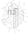
- the fastening body is received non-rotatably in the large drill 12, and its design in detail is based on Fig. 2 described.
- the large drill 12 also has an SDS-max shank 30, it being understood that any other shank design can also be used.
- the large drill 12 is designed as a crown drill in the illustrated embodiment. For this purpose it has, in a manner known per se, a hollow cylinder 32 which is open on one side and which is equipped on its front side with hard metal plates 34 distributed over the circumference.
- the hard metal plates 34 are clearly surmounted by the center drill 14, the center drill 14 also being equipped with a hard metal plate 36 in a manner which is also known per se.
- the fastening body 26 is arranged on the thickened shank area 38 of the large drill 12. It goes without saying that instead of this, an arrangement at the transition 40 or at any other suitable point on the large drill 12 is also possible.
- the fastening body 26 is formed in one piece and has three sections, namely - viewed from the drill axis 44 - the pin 24, a storage surface 46 and an external thread 48.
- the pin 24 protrudes into the blind hole 16 in the large drill 12, while the contact surface 46 and the external thread 48 are received in a passage recess 50 for receiving the fastening body in the large drill 12.
- the passage recess 50 has an opposing contact surface 52.
- the mating contact surface 52 and the contact surface 56 extend conically with a conical angle which holds the fastening body 26 in the passage recess 50 in a self-locking manner.
- the external thread 46 is formed, the diameter of which is somewhat larger than the diameter of the contact surface 46. It fits an internal thread 54 in the passage recess 50.
- a circular ring surface 58 is formed, which causes a jump in diameter between the contact surface 46 and the pin 24.
- the circular ring surface 58 points with its surface normal to the axis 46 and is slightly spaced from the center drill 14. This configuration has the effect that the axial contact for screwing in the fastening body 26 is not on this circular ring surface 58 and also not via the contact between the pin 24 and a groove bottom 60 of the groove 22 is implemented, but via the contact between the contact surface 46 and the counter contact surface 52.
- the groove 22 ends in fillets 64 and 66, which extend semicircularly, with a diameter that essentially corresponds to the diameter of the pin 24.
- the pin 24 has a length-to-diameter ratio of one to one. While the groove 22 is designed as a flat groove in the illustrated embodiment, it goes without saying that any other configuration, for example as a round groove, trapezoidal groove or cylinder groove, or also as a V groove, can be considered instead of a flat groove.
- the pin 24 also does not have to be cylindrical, but can have any round, angular or conical shape, it being preferred that the extent of the side flanks of the groove 22 and the outer surfaces of the pin 24 are selected to match each other.
- a detachable but secure mounting of the fastening body 26 in the large drill 12 is otherwise favorable.
- a driver profile (not shown) for screw actuation is provided on the enclosed outer side 70 of the fastening body 26, for example a hexagon socket.
Landscapes
- Engineering & Computer Science (AREA)
- Mechanical Engineering (AREA)
- Drilling Tools (AREA)
- Earth Drilling (AREA)
Claims (14)
- Outil de forage (10) avec un grand foret (12), en particulier un foret à couronne, dans lequel un foret de centrage (14) est guidé axialement de manière mobile, où le mouvement axial du foret de centrage (14) par rapport au grand foret (12) est limité par au moins une butée, au moins une broche (24), qui est montée sur le grand foret (12), sa tige (38) ou une transition (40) entre ces deux, s'étend dans la direction axiale de la broche (24) vers le foret de centrage (14), où la broche (24) est formée sur un corps de fixation (26) faisant saillie vers l'intérieur à partir de celui-ci dans la direction radiale de l'outil de forage (10), caractérisé en ce que le corps de fixation (28) présente une surface de contact (46), qui se repose contre une surface de contact conjuguée (52) de l'outil de forage (10) et qui, en particulier, présente au moins partiellement une extension transversale plus importante que la tige (24), et la surface de contact (46) est conçue comme une surface conique qui s'étend de manière autobloquante avec un angle de cône vers la tige (24) inférieur à 15 degrés et supérieur à 0,5 degré et, en particulier, de 2 à 8 degrés.
- Outil de forage selon la revendication 1, caractérisé en ce que la broche (24) est fixée dans le grand foret (12), sa tige (18) ou une transition entre ces deux et fait saillie dans un évidement, en particulier une rainure (22), du foret de centrage (14) pour l'entrainement en rotation de celui-ci.
- Outil de forage selon l'une des revendications précédentes, caractérisé en ce que la tige (24) et la surface de contact (46) sont toutes deux de forme circulaire et la surface de contact se fond dans la tige et l'extension transversale forme le diamètre de la surface de contact.
- Outil de forage selon l'une des revendications précédentes, caractérisé en ce que la transition entre la tige (24) et la surface de contact (46) est formée sur un épaulement, qui forme en particulier une surface annulaire (58), dont la surface normale - par rapport au grand foret (12) - est dirigée radialement vers l'intérieur.
- Outil de forage selon l'une des revendications précédentes, caractérisé en ce que le diamètre de la surface de contact (46) à son point le plus petit est au moins une fois et demie supérieure au diamètre de la tige (24), en particulier moins de 4 fois et de préférence environ deux fois supérieure.
- Outil de forage selon l'une des revendications précédentes, caractérisé en ce que le corps de fixation (26) présente un filetage extérieur (46) qui est disposé sur le côté de la surface d'appui opposé à la broche (24) et qui présente un diamètre identique ou en particulier supérieur à la surface d'appui et qui s'engage dans un filetage intérieur (54) de l'outil de forage (10).
- Outil de forage selon l'une des revendications précédentes, caractérisé en ce que le corps de fixation (26) est formé de la séquence broche - surface de contact - filetage de diamètre croissant, où la longueur axiale du filet et de la surface de contact (46) est sensiblement égale et en particulier de 20 % à 100 %, de préférence environ 50 %, supérieure à la longueur axiale de la broche.
- Outil de forage selon l'une des revendications précédentes, caractérisé en ce qu'une rainure (22) est formée dans le foret central (14) de l'outil de forage (10), qui s'étend sensiblement parallèlement à l'axe et se termine en particulier chacune en demi-cercle, et en ce qu'une surface d'entraînement en rotation est formée sur un flanc de la rainure.
- Outil de forage selon la revendication 8, caractérisé en ce que la rainure (22) s'étend dans la zone entre l'axe (44) du foret central (14) et la circonférence extérieure de celui-ci et présente un fond de rainure plat. et dont la normale à la surface s'étend radialement vers l'extérieur par rapport au foret central, où le fond de rainure est en particulier espacé à moins d'un demi-rayon du foret centra! de son axe.
- Outil de forage selon l'une des revendications précédentes, caractérisé en ce que la tige (24) est conçue comme une tige ronde qui présente un rapport longueur/diamètre compris entre 0,5 et 2,0, en particulier entre 0,75 et 1,5 et de manière particulièrement préférée environ de 1,0, et qui s'engage dans une rainure (22) du foret central (14), et en ce que la rainure se rétrécit en particulier en filets semi-circulaires.
- Outil de forage selon l'une des revendications précédentes, caractérisé en ce que la tige (24) fait saillie dans une rainure (22) du foret central (14), en particulier sur une extension comprise entre 0,35 et 0,95 de la profondeur de la rainure et, de manière particulièrement préférée, sur plus de 60% de la profondeur de la rainure.
- Outil de forage selon l'une des revendications précédentes, caractérisé en ce que la surface d'épaulement annulaire (58) du corps de fixation (26) en direction de l'axe (24) est espacée radialement du foret central (14) de plus de 50 µm, en particulier de plus de 0,2 mm, à l'état monté.
- Outil de forage selon l'une des revendications précédentes, caractérisé en ce que dans la tige (18) ou la zone de transition de l'outil de forage (10) est formé un évidement traversant (50) qui reçoit le corps de fixation (26) et qui, lorsque le foret de centrage (14) est à l'état inséré, est aligné avec sa rainure (22), où l'évidement traversant présente en particulier un filetage intérieur (54).
- Outil de forage selon l'une des revendications précédentes, caractérisé en ce que l'appui de la surface de butée du corps de fixation (26) contre la surface de contrebutée (52) dans l'outil de forage (10) forme une butée pour la profondeur de pénétration de la tige (24) dans la rainure (22) du foret de centrage (14).
Applications Claiming Priority (1)
| Application Number | Priority Date | Filing Date | Title |
|---|---|---|---|
| DE102010061214.6A DE102010061214B4 (de) | 2010-12-14 | 2010-12-14 | Bohrwerkzeug |
Publications (2)
| Publication Number | Publication Date |
|---|---|
| EP2465627A1 EP2465627A1 (fr) | 2012-06-20 |
| EP2465627B1 true EP2465627B1 (fr) | 2020-12-30 |
Family
ID=45318934
Family Applications (1)
| Application Number | Title | Priority Date | Filing Date |
|---|---|---|---|
| EP11192661.4A Active EP2465627B1 (fr) | 2010-12-14 | 2011-12-08 | Outil de forage |
Country Status (4)
| Country | Link |
|---|---|
| US (1) | US8794881B2 (fr) |
| EP (1) | EP2465627B1 (fr) |
| DE (1) | DE102010061214B4 (fr) |
| HU (1) | HUE053724T2 (fr) |
Families Citing this family (8)
| Publication number | Priority date | Publication date | Assignee | Title |
|---|---|---|---|---|
| USD748170S1 (en) * | 2013-11-27 | 2016-01-26 | Nir Velozny | Connector for construction drilling cup |
| USD748702S1 (en) * | 2013-11-27 | 2016-02-02 | Nir Velozny | Accessory for inner ring of drilling cup and for housing of electrical appliances |
| USD748701S1 (en) * | 2013-11-27 | 2016-02-02 | Nir Velozny | Inner ring of a construction drilling cup |
| USD748700S1 (en) * | 2013-11-27 | 2016-02-02 | Nir Velozny | Construction drilling cup |
| DE202017100778U1 (de) * | 2017-02-14 | 2018-05-16 | Wolfcraft Gmbh | Lochsäge |
| US10596642B2 (en) * | 2017-08-23 | 2020-03-24 | Gemini Precision Machining, Inc. | Tool and tool holder assembly |
| CN108556149A (zh) * | 2018-04-23 | 2018-09-21 | 朱群成 | 一种建筑监测仪器安装用开槽设备 |
| CN108748712B (zh) * | 2018-05-30 | 2021-04-20 | 张文强 | 一种机电用节能型楼面钻孔机 |
Family Cites Families (20)
| Publication number | Priority date | Publication date | Assignee | Title |
|---|---|---|---|---|
| US1441994A (en) * | 1919-08-27 | 1923-01-09 | Adolph Mueller | Shell cutter and drill for drilling machines |
| US1430932A (en) * | 1921-12-08 | 1922-10-03 | Ole K Bogstrand | Tool |
| DE1294611B (de) * | 1963-10-22 | 1969-05-08 | Dingerkus Geb | Griffbefestigung fuer Isoliergriffe an Toepfen od. dgl. |
| FR1449017A (fr) * | 1965-07-01 | 1966-08-12 | Chausson Usines Sa | Dispositif pour le perçage de corps creux |
| DE2913501A1 (de) * | 1979-04-04 | 1980-10-16 | Bosch Gmbh Robert | Hohlbohrer mit bohrkrone |
| DE3113688C3 (de) * | 1980-12-10 | 1996-01-11 | Miyanaga Kk | Bohrwerkzeug, insbesondere zum Ausschneiden von Scheiben aus plattenförmigen metallischen Werkstücken |
| JPS57157409U (fr) * | 1981-03-25 | 1982-10-02 | ||
| JPS57201114A (en) * | 1981-05-29 | 1982-12-09 | Oomi Kogyo Kk | Boring cutter |
| DE8521577U1 (de) | 1985-07-26 | 1986-04-17 | Lindhorst, Jürgen, 2000 Hamburg | Kronenbohrwerkzeug zum vorzugsweisen Bohren in Gestein, Mauerwerk od. dgl. |
| US5049010A (en) * | 1988-08-04 | 1991-09-17 | Unibit Corporation | Metal cutting tool |
| US4992009A (en) * | 1988-08-25 | 1991-02-12 | Canadian Flexi Drills | Sheet metal drill bit |
| DE3930250A1 (de) * | 1989-09-11 | 1991-03-14 | Licentia Gmbh | Mit der arbeitsspindel einer handgefuehrten elektrowerkzeugmaschine vereinigbarer aufnahmeschaft |
| EP0732164B1 (fr) * | 1995-03-17 | 1999-08-25 | Hawera Probst GmbH | Outil de perçage, en particulier pour le perçage par percussion de la pierre |
| US5813802A (en) | 1995-11-30 | 1998-09-29 | House B.M. Co., Ltd. | Drilling tool assembly and its center drill and cup shape drill |
| DE19740277B4 (de) | 1997-09-13 | 2012-05-24 | Robert Bosch Gmbh | Bohrwerkzeug |
| DE19748987B4 (de) | 1997-11-06 | 2007-11-22 | Robert Bosch Gmbh | Bohrwerkzeug insbesondere für drehschlagendes Bohren von vorzugsweise Gestein |
| JP4357657B2 (ja) * | 1999-06-22 | 2009-11-04 | 株式会社ハウスビーエム | 孔開け工具の製造方法 |
| US6375396B1 (en) * | 2000-03-27 | 2002-04-23 | Jancy Engineering Company | Hole cutting tool with drill pilot |
| US6599063B1 (en) * | 2002-08-31 | 2003-07-29 | Richard E. Capstran | Hole saw having efficient slug removal |
| US7967535B2 (en) * | 2008-08-20 | 2011-06-28 | Cecil Eiserer | Hole saw with waste plug ejector |
-
2010
- 2010-12-14 DE DE102010061214.6A patent/DE102010061214B4/de not_active Expired - Fee Related
-
2011
- 2011-12-08 HU HUE11192661A patent/HUE053724T2/hu unknown
- 2011-12-08 EP EP11192661.4A patent/EP2465627B1/fr active Active
- 2011-12-12 US US13/323,645 patent/US8794881B2/en active Active
Non-Patent Citations (1)
| Title |
|---|
| None * |
Also Published As
| Publication number | Publication date |
|---|---|
| US20120148359A1 (en) | 2012-06-14 |
| DE102010061214B4 (de) | 2018-02-15 |
| DE102010061214A1 (de) | 2012-06-14 |
| HUE053724T2 (hu) | 2021-07-28 |
| EP2465627A1 (fr) | 2012-06-20 |
| US8794881B2 (en) | 2014-08-05 |
Similar Documents
| Publication | Publication Date | Title |
|---|---|---|
| EP2465627B1 (fr) | Outil de forage | |
| EP3215330B1 (fr) | Outillage d'une fraiseuse de sol et fraiseuse de sol équipée d'un tel outillage | |
| CH621391A5 (fr) | ||
| DE19712784C2 (de) | Schraube | |
| EP3467255A1 (fr) | Porte-burin | |
| CH714193A2 (de) | Bohrkrone. | |
| EP2331282A1 (fr) | Taraud | |
| DE102007028267B4 (de) | Verbesserte Ankermutter aus faserverstärktem Kunststoff | |
| AT509643B1 (de) | Zweiteiliges bohrwerkzeug zum schlag- oder drehschlagbohren von löchern in boden- oder gesteinsmaterial | |
| EP1183477A1 (fr) | Dispositif de rattrapage d'usure des garnitures de freins | |
| DE102020122655B3 (de) | Schneidkronenbefestigung | |
| DE202018103106U1 (de) | Bohrschraube | |
| EP3912761A1 (fr) | Porte-mèche pourvu de dispositif de protection contre les impulsions de charge | |
| EP3241948A1 (fr) | Outil de fraisage rotatif comprenant une pluralité de têtes d'outil amovibles et tête d'outil pour un tel outil de fraisage rotatif | |
| DE202012101328U1 (de) | Schraube für das Befestigen eines Holzteiles an einer Unterkonstruktion | |
| EP0077769B1 (fr) | Outil à usage multiple avec élément d'outil exchangeable | |
| EP2345496A1 (fr) | Porte-outil | |
| EP2633959B1 (fr) | Dispositif de fixation sécurisée d'un manche en bois dans l'emmanchure d'une tête de marteau ainsi qu'une vis destinée à la fixation d'un manche en bois dans l'emmanchure d'une tête de marteau | |
| WO2004092542A1 (fr) | Corps de coupe cylindrique | |
| DE3242144C2 (de) | Dreh-Kippmeißel | |
| DE2134781B2 (de) | Setzwerkzeug zum Eintreiben einer Gewindestange | |
| DE10224517A1 (de) | Befestigungsteil für eine diebstahlgesicherte Befestigung eines Fahrzeugrades an einer Radnabe | |
| EP2754854B1 (fr) | Procédé de fixation d'un pic ainsi que dispositif correspondant | |
| DE3608785C2 (fr) | ||
| DE7901696U1 (de) | Schraubenkopf |
Legal Events
| Date | Code | Title | Description |
|---|---|---|---|
| PUAI | Public reference made under article 153(3) epc to a published international application that has entered the european phase |
Free format text: ORIGINAL CODE: 0009012 |
|
| AK | Designated contracting states |
Kind code of ref document: A1 Designated state(s): AL AT BE BG CH CY CZ DE DK EE ES FI FR GB GR HR HU IE IS IT LI LT LU LV MC MK MT NL NO PL PT RO RS SE SI SK SM TR |
|
| AX | Request for extension of the european patent |
Extension state: BA ME |
|
| 17P | Request for examination filed |
Effective date: 20121217 |
|
| 17Q | First examination report despatched |
Effective date: 20160718 |
|
| STAA | Information on the status of an ep patent application or granted ep patent |
Free format text: STATUS: EXAMINATION IS IN PROGRESS |
|
| GRAP | Despatch of communication of intention to grant a patent |
Free format text: ORIGINAL CODE: EPIDOSNIGR1 |
|
| STAA | Information on the status of an ep patent application or granted ep patent |
Free format text: STATUS: GRANT OF PATENT IS INTENDED |
|
| INTG | Intention to grant announced |
Effective date: 20200630 |
|
| GRAS | Grant fee paid |
Free format text: ORIGINAL CODE: EPIDOSNIGR3 |
|
| GRAA | (expected) grant |
Free format text: ORIGINAL CODE: 0009210 |
|
| STAA | Information on the status of an ep patent application or granted ep patent |
Free format text: STATUS: THE PATENT HAS BEEN GRANTED |
|
| AK | Designated contracting states |
Kind code of ref document: B1 Designated state(s): AL AT BE BG CH CY CZ DE DK EE ES FI FR GB GR HR HU IE IS IT LI LT LU LV MC MK MT NL NO PL PT RO RS SE SI SK SM TR |
|
| REG | Reference to a national code |
Ref country code: GB Ref legal event code: FG4D Free format text: NOT ENGLISH |
|
| REG | Reference to a national code |
Ref country code: AT Ref legal event code: REF Ref document number: 1349431 Country of ref document: AT Kind code of ref document: T Effective date: 20210115 |
|
| REG | Reference to a national code |
Ref country code: DE Ref legal event code: R096 Ref document number: 502011017026 Country of ref document: DE |
|
| REG | Reference to a national code |
Ref country code: IE Ref legal event code: FG4D Free format text: LANGUAGE OF EP DOCUMENT: GERMAN |
|
| REG | Reference to a national code |
Ref country code: CH Ref legal event code: NV Representative=s name: KELLER SCHNEIDER PATENT- UND MARKENANWAELTE AG, CH |
|
| PG25 | Lapsed in a contracting state [announced via postgrant information from national office to epo] |
Ref country code: NO Free format text: LAPSE BECAUSE OF FAILURE TO SUBMIT A TRANSLATION OF THE DESCRIPTION OR TO PAY THE FEE WITHIN THE PRESCRIBED TIME-LIMIT Effective date: 20210330 Ref country code: RS Free format text: LAPSE BECAUSE OF FAILURE TO SUBMIT A TRANSLATION OF THE DESCRIPTION OR TO PAY THE FEE WITHIN THE PRESCRIBED TIME-LIMIT Effective date: 20201230 Ref country code: FI Free format text: LAPSE BECAUSE OF FAILURE TO SUBMIT A TRANSLATION OF THE DESCRIPTION OR TO PAY THE FEE WITHIN THE PRESCRIBED TIME-LIMIT Effective date: 20201230 Ref country code: GR Free format text: LAPSE BECAUSE OF FAILURE TO SUBMIT A TRANSLATION OF THE DESCRIPTION OR TO PAY THE FEE WITHIN THE PRESCRIBED TIME-LIMIT Effective date: 20210331 |
|
| PG25 | Lapsed in a contracting state [announced via postgrant information from national office to epo] |
Ref country code: SE Free format text: LAPSE BECAUSE OF FAILURE TO SUBMIT A TRANSLATION OF THE DESCRIPTION OR TO PAY THE FEE WITHIN THE PRESCRIBED TIME-LIMIT Effective date: 20201230 Ref country code: LV Free format text: LAPSE BECAUSE OF FAILURE TO SUBMIT A TRANSLATION OF THE DESCRIPTION OR TO PAY THE FEE WITHIN THE PRESCRIBED TIME-LIMIT Effective date: 20201230 Ref country code: BG Free format text: LAPSE BECAUSE OF FAILURE TO SUBMIT A TRANSLATION OF THE DESCRIPTION OR TO PAY THE FEE WITHIN THE PRESCRIBED TIME-LIMIT Effective date: 20210330 |
|
| REG | Reference to a national code |
Ref country code: NL Ref legal event code: MP Effective date: 20201230 |
|
| PG25 | Lapsed in a contracting state [announced via postgrant information from national office to epo] |
Ref country code: HR Free format text: LAPSE BECAUSE OF FAILURE TO SUBMIT A TRANSLATION OF THE DESCRIPTION OR TO PAY THE FEE WITHIN THE PRESCRIBED TIME-LIMIT Effective date: 20201230 |
|
| REG | Reference to a national code |
Ref country code: LT Ref legal event code: MG9D |
|
| REG | Reference to a national code |
Ref country code: HU Ref legal event code: AG4A Ref document number: E053724 Country of ref document: HU |
|
| PG25 | Lapsed in a contracting state [announced via postgrant information from national office to epo] |
Ref country code: LT Free format text: LAPSE BECAUSE OF FAILURE TO SUBMIT A TRANSLATION OF THE DESCRIPTION OR TO PAY THE FEE WITHIN THE PRESCRIBED TIME-LIMIT Effective date: 20201230 Ref country code: PT Free format text: LAPSE BECAUSE OF FAILURE TO SUBMIT A TRANSLATION OF THE DESCRIPTION OR TO PAY THE FEE WITHIN THE PRESCRIBED TIME-LIMIT Effective date: 20210430 Ref country code: RO Free format text: LAPSE BECAUSE OF FAILURE TO SUBMIT A TRANSLATION OF THE DESCRIPTION OR TO PAY THE FEE WITHIN THE PRESCRIBED TIME-LIMIT Effective date: 20201230 Ref country code: SK Free format text: LAPSE BECAUSE OF FAILURE TO SUBMIT A TRANSLATION OF THE DESCRIPTION OR TO PAY THE FEE WITHIN THE PRESCRIBED TIME-LIMIT Effective date: 20201230 Ref country code: CZ Free format text: LAPSE BECAUSE OF FAILURE TO SUBMIT A TRANSLATION OF THE DESCRIPTION OR TO PAY THE FEE WITHIN THE PRESCRIBED TIME-LIMIT Effective date: 20201230 Ref country code: EE Free format text: LAPSE BECAUSE OF FAILURE TO SUBMIT A TRANSLATION OF THE DESCRIPTION OR TO PAY THE FEE WITHIN THE PRESCRIBED TIME-LIMIT Effective date: 20201230 Ref country code: NL Free format text: LAPSE BECAUSE OF FAILURE TO SUBMIT A TRANSLATION OF THE DESCRIPTION OR TO PAY THE FEE WITHIN THE PRESCRIBED TIME-LIMIT Effective date: 20201230 |
|
| PG25 | Lapsed in a contracting state [announced via postgrant information from national office to epo] |
Ref country code: PL Free format text: LAPSE BECAUSE OF FAILURE TO SUBMIT A TRANSLATION OF THE DESCRIPTION OR TO PAY THE FEE WITHIN THE PRESCRIBED TIME-LIMIT Effective date: 20201230 |
|
| PG25 | Lapsed in a contracting state [announced via postgrant information from national office to epo] |
Ref country code: IS Free format text: LAPSE BECAUSE OF FAILURE TO SUBMIT A TRANSLATION OF THE DESCRIPTION OR TO PAY THE FEE WITHIN THE PRESCRIBED TIME-LIMIT Effective date: 20210430 |
|
| REG | Reference to a national code |
Ref country code: DE Ref legal event code: R097 Ref document number: 502011017026 Country of ref document: DE |
|
| PG25 | Lapsed in a contracting state [announced via postgrant information from national office to epo] |
Ref country code: AL Free format text: LAPSE BECAUSE OF FAILURE TO SUBMIT A TRANSLATION OF THE DESCRIPTION OR TO PAY THE FEE WITHIN THE PRESCRIBED TIME-LIMIT Effective date: 20201230 Ref country code: IT Free format text: LAPSE BECAUSE OF FAILURE TO SUBMIT A TRANSLATION OF THE DESCRIPTION OR TO PAY THE FEE WITHIN THE PRESCRIBED TIME-LIMIT Effective date: 20201230 |
|
| PLBE | No opposition filed within time limit |
Free format text: ORIGINAL CODE: 0009261 |
|
| STAA | Information on the status of an ep patent application or granted ep patent |
Free format text: STATUS: NO OPPOSITION FILED WITHIN TIME LIMIT |
|
| PG25 | Lapsed in a contracting state [announced via postgrant information from national office to epo] |
Ref country code: DK Free format text: LAPSE BECAUSE OF FAILURE TO SUBMIT A TRANSLATION OF THE DESCRIPTION OR TO PAY THE FEE WITHIN THE PRESCRIBED TIME-LIMIT Effective date: 20201230 Ref country code: ES Free format text: LAPSE BECAUSE OF FAILURE TO SUBMIT A TRANSLATION OF THE DESCRIPTION OR TO PAY THE FEE WITHIN THE PRESCRIBED TIME-LIMIT Effective date: 20201230 |
|
| 26N | No opposition filed |
Effective date: 20211001 |
|
| PG25 | Lapsed in a contracting state [announced via postgrant information from national office to epo] |
Ref country code: SI Free format text: LAPSE BECAUSE OF FAILURE TO SUBMIT A TRANSLATION OF THE DESCRIPTION OR TO PAY THE FEE WITHIN THE PRESCRIBED TIME-LIMIT Effective date: 20201230 |
|
| PG25 | Lapsed in a contracting state [announced via postgrant information from national office to epo] |
Ref country code: IS Free format text: LAPSE BECAUSE OF FAILURE TO SUBMIT A TRANSLATION OF THE DESCRIPTION OR TO PAY THE FEE WITHIN THE PRESCRIBED TIME-LIMIT Effective date: 20210430 |
|
| PG25 | Lapsed in a contracting state [announced via postgrant information from national office to epo] |
Ref country code: MC Free format text: LAPSE BECAUSE OF FAILURE TO SUBMIT A TRANSLATION OF THE DESCRIPTION OR TO PAY THE FEE WITHIN THE PRESCRIBED TIME-LIMIT Effective date: 20201230 |
|
| REG | Reference to a national code |
Ref country code: BE Ref legal event code: MM Effective date: 20211231 |
|
| PG25 | Lapsed in a contracting state [announced via postgrant information from national office to epo] |
Ref country code: LU Free format text: LAPSE BECAUSE OF NON-PAYMENT OF DUE FEES Effective date: 20211208 Ref country code: IE Free format text: LAPSE BECAUSE OF NON-PAYMENT OF DUE FEES Effective date: 20211208 |
|
| PG25 | Lapsed in a contracting state [announced via postgrant information from national office to epo] |
Ref country code: BE Free format text: LAPSE BECAUSE OF NON-PAYMENT OF DUE FEES Effective date: 20211231 |
|
| PG25 | Lapsed in a contracting state [announced via postgrant information from national office to epo] |
Ref country code: CY Free format text: LAPSE BECAUSE OF FAILURE TO SUBMIT A TRANSLATION OF THE DESCRIPTION OR TO PAY THE FEE WITHIN THE PRESCRIBED TIME-LIMIT Effective date: 20201230 |
|
| P01 | Opt-out of the competence of the unified patent court (upc) registered |
Effective date: 20230530 |
|
| PG25 | Lapsed in a contracting state [announced via postgrant information from national office to epo] |
Ref country code: SM Free format text: LAPSE BECAUSE OF FAILURE TO SUBMIT A TRANSLATION OF THE DESCRIPTION OR TO PAY THE FEE WITHIN THE PRESCRIBED TIME-LIMIT Effective date: 20201230 |
|
| PG25 | Lapsed in a contracting state [announced via postgrant information from national office to epo] |
Ref country code: MK Free format text: LAPSE BECAUSE OF FAILURE TO SUBMIT A TRANSLATION OF THE DESCRIPTION OR TO PAY THE FEE WITHIN THE PRESCRIBED TIME-LIMIT Effective date: 20201230 |
|
| PG25 | Lapsed in a contracting state [announced via postgrant information from national office to epo] |
Ref country code: MT Free format text: LAPSE BECAUSE OF FAILURE TO SUBMIT A TRANSLATION OF THE DESCRIPTION OR TO PAY THE FEE WITHIN THE PRESCRIBED TIME-LIMIT Effective date: 20201230 |
|
| PG25 | Lapsed in a contracting state [announced via postgrant information from national office to epo] |
Ref country code: TR Free format text: LAPSE BECAUSE OF FAILURE TO SUBMIT A TRANSLATION OF THE DESCRIPTION OR TO PAY THE FEE WITHIN THE PRESCRIBED TIME-LIMIT Effective date: 20201230 |
|
| REG | Reference to a national code |
Ref country code: CH Ref legal event code: U11 Free format text: ST27 STATUS EVENT CODE: U-0-0-U10-U11 (AS PROVIDED BY THE NATIONAL OFFICE) Effective date: 20260101 |
|
| PGFP | Annual fee paid to national office [announced via postgrant information from national office to epo] |
Ref country code: GB Payment date: 20251223 Year of fee payment: 15 |
|
| PGFP | Annual fee paid to national office [announced via postgrant information from national office to epo] |
Ref country code: AT Payment date: 20251218 Year of fee payment: 15 |
|
| PGFP | Annual fee paid to national office [announced via postgrant information from national office to epo] |
Ref country code: HU Payment date: 20251212 Year of fee payment: 15 Ref country code: FR Payment date: 20251223 Year of fee payment: 15 |
|
| PGFP | Annual fee paid to national office [announced via postgrant information from national office to epo] |
Ref country code: DE Payment date: 20251210 Year of fee payment: 15 |
|
| PGFP | Annual fee paid to national office [announced via postgrant information from national office to epo] |
Ref country code: CH Payment date: 20260101 Year of fee payment: 15 |