EP2479585A1 - Target object movement estimating device - Google Patents
Target object movement estimating device Download PDFInfo
- Publication number
- EP2479585A1 EP2479585A1 EP12151809A EP12151809A EP2479585A1 EP 2479585 A1 EP2479585 A1 EP 2479585A1 EP 12151809 A EP12151809 A EP 12151809A EP 12151809 A EP12151809 A EP 12151809A EP 2479585 A1 EP2479585 A1 EP 2479585A1
- Authority
- EP
- European Patent Office
- Prior art keywords
- target object
- location
- stationary point
- module
- movement
- Prior art date
- Legal status (The legal status is an assumption and is not a legal conclusion. Google has not performed a legal analysis and makes no representation as to the accuracy of the status listed.)
- Granted
Links
Images


Classifications
-
- G—PHYSICS
- G01—MEASURING; TESTING
- G01S—RADIO DIRECTION-FINDING; RADIO NAVIGATION; DETERMINING DISTANCE OR VELOCITY BY USE OF RADIO WAVES; LOCATING OR PRESENCE-DETECTING BY USE OF THE REFLECTION OR RERADIATION OF RADIO WAVES; ANALOGOUS ARRANGEMENTS USING OTHER WAVES
- G01S7/00—Details of systems according to groups G01S13/00, G01S15/00, G01S17/00
- G01S7/02—Details of systems according to groups G01S13/00, G01S15/00, G01S17/00 of systems according to group G01S13/00
- G01S7/28—Details of pulse systems
- G01S7/285—Receivers
- G01S7/295—Means for transforming co-ordinates or for evaluating data, e.g. using computers
-
- G—PHYSICS
- G01—MEASURING; TESTING
- G01S—RADIO DIRECTION-FINDING; RADIO NAVIGATION; DETERMINING DISTANCE OR VELOCITY BY USE OF RADIO WAVES; LOCATING OR PRESENCE-DETECTING BY USE OF THE REFLECTION OR RERADIATION OF RADIO WAVES; ANALOGOUS ARRANGEMENTS USING OTHER WAVES
- G01S13/00—Systems using the reflection or reradiation of radio waves, e.g. radar systems; Analogous systems using reflection or reradiation of waves whose nature or wavelength is irrelevant or unspecified
- G01S13/02—Systems using reflection of radio waves, e.g. primary radar systems; Analogous systems
- G01S13/50—Systems of measurement based on relative movement of target
- G01S13/58—Velocity or trajectory determination systems; Sense-of-movement determination systems
- G01S13/60—Velocity or trajectory determination systems; Sense-of-movement determination systems wherein the transmitter and receiver are mounted on the moving object, e.g. for determining ground speed, drift angle, ground track
Definitions
- the present invention relates to a target object movement estimating device that estimates movement of a target object based on information relating to the target object which is detected by a detection instrument.
- TT Target Tracking
- ARPA Automatic Radar Plotting Aid
- the target object movement estimating device disclosed in JP3,508,000(B ) creates current location measurement data of the detection target object based on input signals, such as a radar signal relating to a location of the target object, and a course and a speed of a ship equipped with the estimating device, and the location measurement data is then sent to a movement estimating module.
- the movement estimating module calculates a relative motion and a true motion of the detection target object based on the measurement data sent time-sequentially.
- the obtained estimated data of the relative motion and the true motion is suitably outputted to a data display unit, for example in a form of a vector representation.
- JP3,508,000(B ) points out that the location measurement data which is created and sent to the movement estimating module contains various disturbances and, thus, this degrades accuracy of the data estimated by the movement estimating module.
- JP3,508,000(B ) also discloses that the movement estimating module uses a recursive digital filter, such as a Kalman filter and an ⁇ tracker, and calculates a moving average, to perform smoothing to reduce the influence of disturbance, in order to obtain stable estimated data.
- the device disclosed in JP3,508,000(B ) treats a location of the target object obtained from the radar signal as a relative location with respect to the ship location. Therefore, the location measurement data inputted into the movement estimating module depends on the ship's movement in addition to the movement of the detection target object.
- the location measurement data also changes greatly, often resulting in a temporary precision degradation of the estimation by the movement estimating module.
- the smoothing is performed in the movement estimating module as described above, the movement estimation result output will contain a delay and, thus, a certain amount of time is often required to recover the estimation accuracy of the movement estimating module.
- the device disclosed in JP3,508,000(B ) outputs a movement estimation result which indicates the target object is moving at a large true speed even if the ship is stopped in fact, resulting in confusing a user. Therefore, an improvement in this regard is needed.
- the present invention is made in view of the above situations, and provides a target object movement estimating device, that can output a movement estimation result which is less subject to a change in a movement state of the device itself.
- a target object movement estimating device includes a target object relative location acquisition module carried in a movable body and for acquiring, based on a radar echo, a target object relative location that is a relative location of a target object with respect to a location of the device, a stationary point reference target object location acquisition module for acquiring a stationary point reference target object location, that is a location of the target object with respect to a stationary point, based on the target object relative location and the location of the device, and a filtering module for being inputted with the stationary point reference target object location and for estimating movement information on the target object.
- the stationary point reference target object location from which an influence of the movement of the ship is removed is inputted into in the filtering module, and the stationary point reference target object location is used for the estimation of the movement state of the target object. Therefore, even if the output of the filtering module contains a delay, since it can prevent the movement of the ship from giving a negative influence on the estimation of the movement state of the target object and, thus, the movement state of the target object can be estimated more accurately.
- the movement information on the target object estimated by the filtering module may contain a course and a speed of the target object.
- the filtering module may estimate the movement information on the target object based on the previously estimated movement information on the target object and the inputted stationary point reference target object location.
- the filtering module may perform smoothing of the target object location when estimating the movement information on the target object.
- the filtering module may estimate a next target object location based on the estimated movement information on the target object, and the estimated target object location may be used for selecting a target object of which the movement information is to be estimated, and the stationary point reference target object location of the selected target object may be inputted into the filtering module.
- the above configuration in which the stationary point reference target object location is inputted into the filtering module may be especially effective for the case where the output result of the filtering module tends to diverge (i.e., recursive input).
- an acquired azimuth of the radar echo may be sequentially inputted into the target object relative location acquisition module in terms of an azimuth based on the terrestrial reference frame as target object relative location.
- the stationary point reference target object location acquisition module may acquire the location of the device by compensating location information acquired from a GNSS navigation instrument based on an offset between installed locations of a GNSS antenna and a radar antenna.
- the movement state of the target object can be estimated more accurately.
- the stationary point reference target object location into the filtering module or the target object relative location may be selectively inputted into the filtering module by switching.
- the target object relative location is used for the movement estimation, instead of the stationary point reference target object location. Therefore, the degradation of the estimation accuracy of the movement state can be suppressed.
- a radar device includes any one of the above target object movement estimating devices.
- Fig. 1 is a block diagram of a radar device 11 according to this embodiment.
- the radar device 11 is ship radar which is equipped in a ship, such as a fishing boat, and is mainly used for detection of target object(s), such as other ship(s).
- the radar device 11 includes an antenna unit 21 and a signal processor 22.
- the antenna unit 21 is attached to a predetermined location of the ship as a movable body.
- the antenna unit 21 includes a radar antenna 1, a detector 2, and an A/D converter 3.
- the radar antenna 1 transmits a pulse-shaped radio wave with a strong directivity and receives a corresponding echo (reflective wave) from a target object.
- a distance "r" from the ship to the target object can be obtained by measuring a period of time after the radar antenna 1 transmits the pulse-shaped radio wave until it receives the corresponding echo.
- the radar antenna 1 rotates 360° in a horizontal plane.
- the radar antenna 1 repeatedly transmits and receives the pulse-shaped radio wave, while changing a transmitting direction of the radio wave (i.e., changing the angle of the radar antenna 1). Accordingly, the target objects, which exist in the plane, 360° around the ship, can be detected.
- sheep as used herein may refer to an operation after transmitting the pulse-shaped radio wave until a subsequent pulse-shaped radio wave is transmitted
- scan as used herein may refer to an operation of a 360° rotation of the radar antenna 1 while transmitting and receiving the radio waves.
- the detector 2 detects and amplifies the signal received by the radar antenna 1, and then outputs the amplified signal (reception signal) to the A/D converter 3.
- the A/D converter 3 samples the analog reception signal inputted from the detector 2, and then converts it into digital data which is comprised of two or more bits (hereinafter, referred to as "reception data").
- the signal processor 22 includes a sweep memory 4, a binarizing module '5, a target object movement estimating module 6 (target object movement estimating device), an image memory 7, an image processing module 8, and a display unit 9.
- the sweep memory 4 is a buffer memory which can store the reception data in real time by one sweep.
- the reception data sampled during one sweep are stored in a time-series manner. Therefore, based on a read-out address when the reception data is read from the sweep memory 4, a distance "r" to a source of the echo corresponding to the reception data can be calculated.
- data indicative of a current direction of the radar antenna 1 with respect to the ship's bow direction (antenna angle ⁇ ) is outputted from the radar antenna 1. Therefore, when reading the reception data from the sweep memory 4, the location of the echo source corresponding to the reception data can be obtained in terms of polar coordinates (r, ⁇ ).
- the binarizing module 5 binarizes a signal level of the sweep memory 4 by comparing it with a predetermined binarizing threshold. Specifically, when the signal level is above the binarizing threshold, the binarizing module 5 outputs data indicative of "a target object exists" (for example, "1"). On the other hand, when the signal level is below the binarizing threshold, the binarizing module 5 outputs data indicative of "no target object exists” (for example, "0").
- the processing result of the radar echo by the binarizing module 5 (binarized data) is outputted to the target object movement estimating module 6.
- the target object movement estimating module 6 continuously detects and estimates the location and the movement state (e.g., speed vector) of the target object to be tracked among target objects which exist around the ship, and notifies a user of target object(s) to be obstacles.
- the target object to be tracked may be set automatically, or it may be particularly set by the user suitably operating the radar device 11.
- the information on the location and speed of the target object to be tracked is outputted to the image processing module 8. A particular configuration of the target object movement estimating module 6 will be described later.
- the image memory 7 stores a two-dimensional image of raster form.
- the reception data outputted from the sweep memory 4 is outputted to an address after the address is calculated so that a location of the echo is shown on a plane.
- the reception data is plotted on the two-dimensional image and, as a result, a radar image of a raster image format indicative of a situation of the target object(s) around the ship can be generated.
- the image processing module 8 synthesizes the images so that the data of the location and speed of the tracking target object outputted from the target object movement estimating module 6 is superimposed on the radar image stored in the image memory 7. As a result, for example, a synthetic image where the speed vector of the tracking target object is superimposed on the radar image can be generated.
- the display unit 9 is configured to be a known raster-scan display unit to display the processing result of the image processing module 8 on a screen image.
- the target object movement estimating module 6 includes a target object relative coordinate acquisition module 61, a stationary point reference target object coordinates acquisition module 62, an estimating target object selection module 63, a filtering module 64, an estimated true speed acquisition module 65, an estimated relative speed acquisition module 66, and a stationary point memory 67.
- the target object relative coordinate acquisition module 61 evaluates a continuity of the binarized data inputted from the binarizing module 5 on the plane, and extracts data which are determined to be "target objects exist” and collected spatially, and, after that, coordinates of a representative point of the data are acquired. That is, since it can be considered that the spatially collected data indicates an echo from a single or the same target object, the target object relative coordinate acquisition module 61 determines the continuing area determined to be "target objects exist" is the single target object, and then calculates coordinates of a representative point of the continuing area as a location of the target object.
- the antenna angle ⁇ indicative of the direction of the radar antenna 1 is expressed by a relative angle with respect to the ship's bow.
- an azimuth sensor (not illustrated) is attached to the radar antenna 1, and the sensor can output the data indicative of the current direction of the radar antenna 1 in terms of an azimuth ( ⁇ ) based on the terrestrial reference frame.
- the azimuth antenna angle ⁇ relating to the processed sweep indicates an azimuth of the target object with respect to the ship based on the terrestrial reference frame.
- the obtained relative coordinates (Trx, Try) of the target object can be expressed as the location of the target object in the XY coordinate plane where the ship is located at the origin and the Y-axis is oriented toward north.
- the target object relative coordinate acquisition module 61 outputs information on the acquired relative coordinates (Trx, Try) of the target object to the stationary point reference target object coordinates acquisition module 62.
- the stationary point reference target object coordinates acquisition module 62 Based on the location information of the ship which is acquired from the GPS navigation instrument (longitude and latitude), the stationary point reference target object coordinates acquisition module 62 converts the relative coordinates (Trx, Try) of the target object inputted from the target object relative coordinate acquisition module 61 into the coordinates (Tax, Tay) with respect to a suitable stationary point.
- the stationary point may be determined in any manner. However, in this embodiment, the location of the ship which is acquired from the GPS navigation instrument when power is supplied to the radar device 11 is adopted as the stationary point.
- the longitude and latitude of the stationary point which are once set are stored in the stationary point memory 67 provided to the target object movement estimating module 6, and the location of the stationary point never move in principle. However, for example, once when there is no more target object to be tracked, the stationary point may be updated so that it becomes the current ship location, and may then be stored again in the memory 67.
- the stationary point reference target object coordinates acquisition module 62 calculates the location of the ship when the stationary point is used as the reference location. As a result, the ship location (Lx, Ly) on the XY coordinate plane where the stationary point is located at the origin and the Y-axis is oriented toward north can be acquired. Then, based on the ship location (Lx, Ly) and the relative coordinates (Trx, Try) of the target object with respect to the ship, the stationary point reference target object coordinates acquisition module 62 can acquire the coordinates (Tax, Tay) of the target object on the XY coordinate plane where the stationary point is used as the origin and the Y-axis is oriented toward north.
- Tax and Tay can be calculated by the following equations.
- the stationary point reference target object coordinates acquisition module 62 outputs the obtained coordinates (Tax, Tay) of the target object to the estimating target object selection module 63.
- the estimating target object selection module 63 selects from the coordinates (Tax, Tay) of the target object outputted from the stationary point reference target object coordinates acquisition module 62 only the coordinates relating to the target object to be tracked, and then outputs the selected coordinates to the filtering module 64.
- the estimating target object selection module 63 will be inputted with an estimated location of the tracking target object which is outputted from the filtering module 64 at the later process stage.
- the estimating target object selection module 63 extracts only the target object which matches with the estimated location of the tracking target object, and then outputs the stationary point reference coordinates (Tax, Tay) of the target object to the filtering module 64.
- the filtering module 64 estimates based on the coordinates of the target object inputted from the estimating target object selection module 63 the movement information including the moving direction (course) and the moving speed of the tracking target object.
- a known ⁇ tracker or a known Kalman filter may be used, for example.
- the filtering module 64 calculates the estimated location of the tracking target object using the estimated moving location of the tracking target object obtained from the previous scan and the current location of the target object obtained by the estimating target object selection module 63.
- the estimated locations are smoothed by using a recursive digital filter, such as a known ⁇ tracker or Kalman filter, or by calculating a moving average, to calculate the stable estimated locations.
- the filtering module 64 outputs the estimated location of the tracking target object obtained to the image processing module 8.
- the filtering module 64 acquires the moving speed of the tracking target object by calculation.
- the moving speed of the tracking target object can be acquired by calculating a difference between the current estimated location and the previous estimated location, and dividing the difference by a period of time required for the change.
- the obtained moving speed of the tracking target object is outputted to the estimated true speed acquisition module 65.
- the filtering module 64 calculates an estimated location of the tracking target object for the next scan based on the location and the moving speed of the tracking target object.
- the estimated location is outputted to the estimating target object selection module 63, and is then used for the selection of the tracking target object(s).
- the estimated true speed acquisition module 65 acquires the moving speed of the tracking target object inputted from the filtering module 64 as a true speed of the tracking target object. That is, the coordinates (Tax, Tay) of the target object inputted into the filtering module 64 are not based on the ship location but are based on the stationary point, as described above. Therefore, the estimated true speed acquisition module 65 can adopt the moving speed calculated from the estimated locations of the tracking target object by the filtering module 64 as described above as a true speed of the tracking target object as it is.
- the estimated true speed acquisition module 65 outputs the acquired true speed and course of the tracking target object to the estimated relative speed acquisition module 66 and the image processing module 8.
- the estimated relative speed acquisition module 66 subtracts the ship's speed obtained based on GPS navigation data from the true speed of the tracking target object obtained from the estimated true speed acquisition module 65 to obtain the relative speed of the tracking target object with respect to the ship's speed.
- the estimated relative speed acquisition module 66 outputs the obtained relative speed of the tracking target object to the image processing module 8.
- a tracking target object moves straight at a constant speed passing through points a, b and c in this order (i.e., a ⁇ b ⁇ c).
- the relative coordinates (Trx, Try) of the target object calculated by the target object relative coordinate acquisition module 61 can be represented as shown in Fig. 4 .
- the tracking target object is moving straight at the constant speed in fact, its relative coordinates (Trx, Try) are greatly influenced by the circling movement of the ship, and draw a trace which moves zigzag.
- the relative coordinates (Trx, Try) are inputted into a smoothing module, such as a Kalman filter or an ⁇ tracker, as described above. Therefore, the output result of the smoothing module becomes the relative speed of the tracking target object with respect to the ship, and the true speed of the tracking target object is acquired by adding the ship's speed to the relative speed.
- a smoothing module such as a Kalman filter or an ⁇ tracker, as described above. Therefore, the output result of the smoothing module becomes the relative speed of the tracking target object with respect to the ship, and the true speed of the tracking target object is acquired by adding the ship's speed to the relative speed.
- the output of the smoothing module contains a delay, until the movement of the ship is fully reflected in the output of the smoothing module, an estimation accuracy of the true speed is degraded corresponding to the delay of response. Further, if the movement of the ship changes rapidly, a certain amount of time is required to stabilize the output of the smoothing module, and the estimation accuracy of true speed is often degraded
- the stationary point reference coordinates (Tax, Tay) calculated by the stationary point reference target object coordinates acquisition module 62 are inputted into the filtering module 64 in this embodiment. Therefore, the location of the tracking target object will be inputted into the filtering module 64 in a form where the influence by the movement of the ship is removed in advance. Thus, even if the output of the filtering module 64 contains the delay, the negative influence on the estimation of the movement information on the target object due to the movement of the ship can be prevented. Therefore, the movement information on the tracking target object can be estimated more accurately.
- the filtering module 64 estimates the location of the tracking target object based on the current location of the target object, the estimated location of the target object is used for the selection of the target object(s) by the estimating target object selection module 63, and the location(s) of the selected target object(s) are inputted into the filtering module 64 (i.e., "recursive input”).
- the filtering module 64 when a large disorder is produced in the target object location inputted into the filtering module 64, the output of the filtering module 64 often diverges and, thus, a certain amount of time must be needed to converge. Therefore, it is especially advantageous to configure the device so that the stationary point reference coordinates (Tax, Tay) which are the location information, from which the influence of the ship's movement is removed in advance, are inputted into the filtering module 64.
- the binarized data which is outputted to the target object relative coordinate acquisition module 61 from the binarizing module 5, is described.
- the binarized data is expressed by polar coordinates, and, as its angle of deviation, two possible angles may be selectively used: (1) an angle ⁇ of the radar antenna 1 with respect to the ship's bow; and (2) an azimuth ⁇ of the radar antenna 1 based on the terrestrial reference frame.
- the target object relative coordinate acquisition module 61 calculates the relative coordinates (Trx, Try) of the target object based on the polar coordinates (r, ⁇ ) which are expressed using the distance r of the target object from the ship and the azimuth ⁇ of the target object based on the terrestrial reference frame, in this embodiment. Accordingly, for example, since the conversion based on the detection result of the azimuth sensor from the angle ⁇ with respect to the ship's bow into the azimuth ⁇ based on the terrestrial reference frame is no longer necessary, the entire processing can be simplified.
- the accuracy degradation of the azimuth ⁇ can be prevented, for example, even if the ship circles rapidly, and the delay is produced due to the conversion from the angle ⁇ with respect to the ship's bow into the azimuth ⁇ based on the terrestrial reference frame.
- the ship location acquired by the stationary point reference target object coordinates acquisition module 62 based on the GPS navigation data is described.
- the location information indicates the location of the GPS antenna.
- the radar device 11 transmits and receives the radio wave via the radar antenna 1, and the radar antenna 1 and the GPS antenna may not necessarily be located at the same location in plan view of the ship.
- the offset in the location between the radar antenna 1 and the GPS antenna gives a negative influence to the accuracy of the stationary point reference coordinates (Tax, Tay) acquired by the stationary point reference target object coordinates acquisition module 62.
- the information indicative of the spatial relationship between the radar antenna 1 and the GPS antenna may be additionally stored, and an offset compensation based on the spatial relationship may be carried out against the location information acquired from the GPS navigation instrument.
- the ship location can indicate the location of the radar antenna 1 more accurately and, thus, the movement state of the tracking target object can be estimated more accurately.
- the target object movement estimating module 6 provided to the signal processor 22 of this embodiment includes the target object relative coordinate acquisition module 61, the stationary point reference target object coordinates acquisition module 62, and filtering module 64.
- the target object relative coordinate acquisition module 61 is carried in the ship, and acquires the relative coordinates (Trx, Try) indicative of the relative location of the target object with respect to the ship location based on the radar echo.
- the stationary point reference target object coordinates acquisition module 62 acquires the stationary point reference coordinates (Tax, Tay) indicative of the location of the target object with respect to the stationary point based on the relative coordinates (Trx, Try) and the ship location.
- the filtering module 64 is inputted with the stationary point reference coordinates (Tax, Tay), and then estimates the movement information on the target object.
- the stationary point reference coordinates (Tax, Tay) from which the influence of the ship movement is removed are inputted into the filtering module 64, and the coordinates are used for the estimation of the movement state of the target object. Therefore, even if the output of the filtering module 64 contains the delay, since the ships movement does not give any negative influence on the estimation of the movement state of the target object, the movement state of the tracking target object can be estimated more accurately. As a result, a more exact estimation of obstacle(s) is now possible.
- the movement information on the target object estimated by the filtering module 64 contains the course and speed of the target object. Thereby, the course and speed of the tracking target object can be estimated accurately.
- the filtering module 64 estimates the movement information on the target object based on the previously estimated movement information on the target object and the inputted stationary point reference coordinates (Tax, Tay). The filtering module 64 performs smoothing of the target object location when estimating the movement information on the target object. The filtering module 64 then estimates the next target object location based on the estimated movement information on the target object, and the estimated target object location is used for selecting the target object(s) of which the movement information is to be estimated by the estimating target object selection module 63.
- the stationary point reference coordinates (Tax, Tay) of the selected target object(s) are inputted into the filtering module 64.
- the configuration of this embodiment in which the stationary point reference coordinates (Tax, Tay) are inputted into the filtering module 64 instead of the relative coordinates (Trx, Try) of the target object is especially effective to the above configuration in which the output result of the filtering module 64 tends to diverge (i.e., recursive input).
- the acquired azimuths of the radar echoes are sequentially inputted into the target object relative coordinate acquisition module 61 in terms of the azimuths ( ⁇ ) based on the terrestrial reference frame. Thereby, the calculation of the relative coordinates (Trx, Try) of the target object can be simply performed.
- the stationary point reference target object coordinates acquisition module 62 performs the offset compensation to the location information acquired from the GPS navigation instrument based on the installed locations of the GPS antenna and the radar antenna 1. Thereby, the location of the device can also be acquired. Thereby, even if the installed locations of the radar antenna 1 and the GPS antenna are different, the location of the radar antenna 1 can be used as the device location, the movement state of the target object can be estimated more accurately.
- the stationary point reference coordinates (Tax, Tay) or the relative coordinates (Trx, Try) of the target object are selectively inputted into the filtering module 64 by switching.
- the accuracy of the stationary point reference coordinates (Tax, Tay) also decreases to possibly degrade the estimation accuracy of the movement state of the target object, resulting in an opposite effect.
- This modification takes this situation in consideration. That is, when the ship location obtained from the GPS navigation instrument moves north beyond a northern boundary line (e.g., at latitude 85° north), or when it moves south beyond a southern boundary line (e.g., at latitude 85° south), the stationary point reference coordinates (Tax, Tay) are not inputted into the filtering module 64, but, instead, the relative coordinates (Trx, Try) are inputted like the conventional manner.
- the target object speed estimated by the filtering module 64 When the relative coordinates (Trx, Try) are inputted into the filtering module 64, the target object speed estimated by the filtering module 64 also becomes the relative speed. Therefore, in this case, the estimated true speed acquisition module 65 simply acquires the true speed of the target object by adding the ship speed to the relative speed outputted from the filtering module 64. On the other hand, the estimated relative speed acquisition module 66 simply obtains the relative speed outputted from the filtering module 64 as it is as the relative speed of the target object.
- the stationary point reference coordinates (Tax, Tay) are inputted again into the filtering module 64.
- the boundary line of the returning determination may be (slightly) offset from the boundary line of the outward determination in transitioning from the stationary point reference coordinates to the relative coordinates, to achieve a hysteresis determination.
- the returning boundary lines may be set at latitude 80° north and 80° south, respectively (not at latitude 85° north and 85° south).
- the target object movement estimating module of this modification selectively switches the input into the filtering module 64 between the stationary point reference coordinates (Tax, Tay) and the relative coordinates (Trx, Try) according to the ship location acquired from the GPS navigation instrument.
- the relative coordinates are used instead of the stationary point reference coordinates for estimating the movement to suppress the degradation of the estimation accuracy of the movement state.
- the navigation instrument using GPS is adopted as an example of GNSSs.
- the navigation instrument may also be replaced by other types of GNSS navigation instruments.
- target object movement estimating device of the present invention may be carried in an arbitrary movable body, including, but not limited to, a ship, an airplane, an automobile, etc.
Landscapes
- Engineering & Computer Science (AREA)
- Radar, Positioning & Navigation (AREA)
- Remote Sensing (AREA)
- Computer Networks & Wireless Communication (AREA)
- Physics & Mathematics (AREA)
- General Physics & Mathematics (AREA)
- Radar Systems Or Details Thereof (AREA)
- Traffic Control Systems (AREA)
Abstract
Description
- The present invention relates to a target object movement estimating device that estimates movement of a target object based on information relating to the target object which is detected by a detection instrument.
- Conventionally, a device called TT (Target Tracking) and/or ARPA (Automatic Radar Plotting Aid) which estimates and displays a true speed and a relative speed of a target object detected by a radar device while tracking the target object, has been proposed.
JP3,508,000(B - The target object movement estimating device disclosed in
JP3,508,000(B -
JP3,508,000(B JP3,508,000(B - The device disclosed in
JP3,508,000(B - Thus, for example, when a movement state of the ship changes rapidly, the location measurement data also changes greatly, often resulting in a temporary precision degradation of the estimation by the movement estimating module. In addition, since the smoothing is performed in the movement estimating module as described above, the movement estimation result output will contain a delay and, thus, a certain amount of time is often required to recover the estimation accuracy of the movement estimating module.
- In other words, when the ship starts and stops traveling, and changes its course, the device disclosed in
JP3,508,000(B - The present invention is made in view of the above situations, and provides a target object movement estimating device, that can output a movement estimation result which is less subject to a change in a movement state of the device itself.
- According to one aspect of the present invention, a target object movement estimating device is provided. The device includes a target object relative location acquisition module carried in a movable body and for acquiring, based on a radar echo, a target object relative location that is a relative location of a target object with respect to a location of the device, a stationary point reference target object location acquisition module for acquiring a stationary point reference target object location, that is a location of the target object with respect to a stationary point, based on the target object relative location and the location of the device, and a filtering module for being inputted with the stationary point reference target object location and for estimating movement information on the target object.
- Therefore, the stationary point reference target object location from which an influence of the movement of the ship is removed is inputted into in the filtering module, and the stationary point reference target object location is used for the estimation of the movement state of the target object. Therefore, even if the output of the filtering module contains a delay, since it can prevent the movement of the ship from giving a negative influence on the estimation of the movement state of the target object and, thus, the movement state of the target object can be estimated more accurately.
- The movement information on the target object estimated by the filtering module may contain a course and a speed of the target object.
- Therefore, the course and speed of the target object can be estimated accurately.
- The filtering module may estimate the movement information on the target object based on the previously estimated movement information on the target object and the inputted stationary point reference target object location. The filtering module may perform smoothing of the target object location when estimating the movement information on the target object. The filtering module may estimate a next target object location based on the estimated movement information on the target object, and the estimated target object location may be used for selecting a target object of which the movement information is to be estimated, and the stationary point reference target object location of the selected target object may be inputted into the filtering module.
- The above configuration in which the stationary point reference target object location is inputted into the filtering module may be especially effective for the case where the output result of the filtering module tends to diverge (i.e., recursive input).
- In the device, an acquired azimuth of the radar echo may be sequentially inputted into the target object relative location acquisition module in terms of an azimuth based on the terrestrial reference frame as target object relative location.
- Therefore, the calculation of the target object relative location can be performed simply.
- The stationary point reference target object location acquisition module may acquire the location of the device by compensating location information acquired from a GNSS navigation instrument based on an offset between installed locations of a GNSS antenna and a radar antenna.
- Therefore, even if the installed locations of the radar antenna and the GNSS antenna are different from each other, since the location of the radar antenna can be used as the location of the device, the movement state of the target object can be estimated more accurately.
- In the device, according to the location of the device acquired from a GNSS navigation instrument, the stationary point reference target object location into the filtering module or the target object relative location may be selectively inputted into the filtering module by switching.
- Within a latitude range where the positioning accuracy by the GNSS navigation instrument tends to be degraded, the target object relative location is used for the movement estimation, instead of the stationary point reference target object location. Therefore, the degradation of the estimation accuracy of the movement state can be suppressed.
- According to another aspect of the present invention, a radar device is provided. The radar device includes any one of the above target object movement estimating devices.
- Therefore, a useful radar device which can estimate the movement state of the target object more accurately can be provided.
- The present disclosure is illustrated by way of example and not by way of limitation in the figures of the accompanying drawings, in which the like reference numerals indicate like elements and in which:
-
Fig. 1 is a block diagram showing the entire configuration of a radar device according to one embodiment of the present invention; -
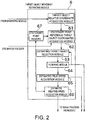
Fig. 2 is a block diagram showing a configuration of a target object movement estimating device shown inFig. 1 ; -
Fig. 3 is a diagram illustrating a case where a ship turns rapidly while a tracking target object moves straight at a constant speed; -
Fig. 4 is a view showing a transition of a relative location of the target object with respect to the ship location in the example ofFig. 3 ; and -
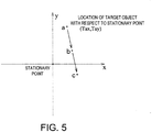
Fig. 5 is a view showing a transition of a location of the target object with respect to a stationary point in the example ofFig. 3 . - Next, one embodiment of the present invention is described with reference to the accompanying drawings.
Fig. 1 is a block diagram of aradar device 11 according to this embodiment. Theradar device 11 is ship radar which is equipped in a ship, such as a fishing boat, and is mainly used for detection of target object(s), such as other ship(s). - As shown in
Fig. 1 , theradar device 11 includes anantenna unit 21 and asignal processor 22. - The
antenna unit 21 is attached to a predetermined location of the ship as a movable body. Theantenna unit 21 includes a radar antenna 1, a detector 2, and an A/D converter 3. - The radar antenna 1 transmits a pulse-shaped radio wave with a strong directivity and receives a corresponding echo (reflective wave) from a target object. With this configuration, a distance "r" from the ship to the target object can be obtained by measuring a period of time after the radar antenna 1 transmits the pulse-shaped radio wave until it receives the corresponding echo. The radar antenna 1 rotates 360° in a horizontal plane. The radar antenna 1 repeatedly transmits and receives the pulse-shaped radio wave, while changing a transmitting direction of the radio wave (i.e., changing the angle of the radar antenna 1). Accordingly, the target objects, which exist in the plane, 360° around the ship, can be detected. The term "sweep" as used herein may refer to an operation after transmitting the pulse-shaped radio wave until a subsequent pulse-shaped radio wave is transmitted, and the term "scan" as used herein may refer to an operation of a 360° rotation of the radar antenna 1 while transmitting and receiving the radio waves.
- The detector 2 detects and amplifies the signal received by the radar antenna 1, and then outputs the amplified signal (reception signal) to the A/D converter 3.
- The A/D converter 3 samples the analog reception signal inputted from the detector 2, and then converts it into digital data which is comprised of two or more bits (hereinafter, referred to as "reception data").
- The
signal processor 22 includes a sweep memory 4, a binarizing module '5, a target object movement estimating module 6 (target object movement estimating device), animage memory 7, animage processing module 8, and adisplay unit 9. - In this embodiment, the sweep memory 4 is a buffer memory which can store the reception data in real time by one sweep. In the sweep memory 4, the reception data sampled during one sweep are stored in a time-series manner. Therefore, based on a read-out address when the reception data is read from the sweep memory 4, a distance "r" to a source of the echo corresponding to the reception data can be calculated. Although illustration is omitted in this example, data indicative of a current direction of the radar antenna 1 with respect to the ship's bow direction (antenna angle α) is outputted from the radar antenna 1. Therefore, when reading the reception data from the sweep memory 4, the location of the echo source corresponding to the reception data can be obtained in terms of polar coordinates (r, α).
- The
binarizing module 5 binarizes a signal level of the sweep memory 4 by comparing it with a predetermined binarizing threshold. Specifically, when the signal level is above the binarizing threshold, thebinarizing module 5 outputs data indicative of "a target object exists" (for example, "1"). On the other hand, when the signal level is below the binarizing threshold, thebinarizing module 5 outputs data indicative of "no target object exists" (for example, "0"). The processing result of the radar echo by the binarizing module 5 (binarized data) is outputted to the target objectmovement estimating module 6. - The target object
movement estimating module 6 continuously detects and estimates the location and the movement state (e.g., speed vector) of the target object to be tracked among target objects which exist around the ship, and notifies a user of target object(s) to be obstacles. The target object to be tracked may be set automatically, or it may be particularly set by the user suitably operating theradar device 11. The information on the location and speed of the target object to be tracked is outputted to theimage processing module 8. A particular configuration of the target objectmovement estimating module 6 will be described later. - In this embodiment, the
image memory 7 stores a two-dimensional image of raster form. The reception data outputted from the sweep memory 4 is outputted to an address after the address is calculated so that a location of the echo is shown on a plane. Thus, the reception data is plotted on the two-dimensional image and, as a result, a radar image of a raster image format indicative of a situation of the target object(s) around the ship can be generated. - The
image processing module 8 synthesizes the images so that the data of the location and speed of the tracking target object outputted from the target objectmovement estimating module 6 is superimposed on the radar image stored in theimage memory 7. As a result, for example, a synthetic image where the speed vector of the tracking target object is superimposed on the radar image can be generated. - In this embodiment, the
display unit 9 is configured to be a known raster-scan display unit to display the processing result of theimage processing module 8 on a screen image. - Next, with reference to
Fig. 2 , the detailed configuration of the target objectmovement estimating module 6 is described. The target objectmovement estimating module 6 includes a target object relative coordinateacquisition module 61, a stationary point reference target object coordinatesacquisition module 62, an estimating targetobject selection module 63, afiltering module 64, an estimated truespeed acquisition module 65, an estimated relative speed acquisition module 66, and astationary point memory 67. - The target object relative coordinate
acquisition module 61 evaluates a continuity of the binarized data inputted from thebinarizing module 5 on the plane, and extracts data which are determined to be "target objects exist" and collected spatially, and, after that, coordinates of a representative point of the data are acquired. That is, since it can be considered that the spatially collected data indicates an echo from a single or the same target object, the target object relative coordinateacquisition module 61 determines the continuing area determined to be "target objects exist" is the single target object, and then calculates coordinates of a representative point of the continuing area as a location of the target object. - The antenna angle α indicative of the direction of the radar antenna 1 is expressed by a relative angle with respect to the ship's bow. Meanwhile, an azimuth sensor (not illustrated) is attached to the radar antenna 1, and the sensor can output the data indicative of the current direction of the radar antenna 1 in terms of an azimuth (θ) based on the terrestrial reference frame. As described above, the azimuth antenna angle θ relating to the processed sweep indicates an azimuth of the target object with respect to the ship based on the terrestrial reference frame.
- The target object relative coordinate
acquisition module 61 calculates a relative location (Trx, Try) of the target object in an XY coordinate system based on the polar coordinates (r, θ) expressed using the distance "r" of the target object from the ship and the azimuth θ of the target object based on the terrestrial reference frame. Specifically, Trx and Try can be calculated by the following equations.

The obtained relative coordinates (Trx, Try) of the target object can be expressed as the location of the target object in the XY coordinate plane where the ship is located at the origin and the Y-axis is oriented toward north. The target object relative coordinateacquisition module 61 outputs information on the acquired relative coordinates (Trx, Try) of the target object to the stationary point reference target object coordinatesacquisition module 62. - Based on the location information of the ship which is acquired from the GPS navigation instrument (longitude and latitude), the stationary point reference target object coordinates
acquisition module 62 converts the relative coordinates (Trx, Try) of the target object inputted from the target object relative coordinateacquisition module 61 into the coordinates (Tax, Tay) with respect to a suitable stationary point. - The stationary point may be determined in any manner. However, in this embodiment, the location of the ship which is acquired from the GPS navigation instrument when power is supplied to the
radar device 11 is adopted as the stationary point. The longitude and latitude of the stationary point which are once set are stored in thestationary point memory 67 provided to the target objectmovement estimating module 6, and the location of the stationary point never move in principle. However, for example, once when there is no more target object to be tracked, the stationary point may be updated so that it becomes the current ship location, and may then be stored again in thememory 67. - After acquiring the current longitude and latitude of the ship from the GPS navigation instrument, the stationary point reference target object coordinates
acquisition module 62 calculates the location of the ship when the stationary point is used as the reference location. As a result, the ship location (Lx, Ly) on the XY coordinate plane where the stationary point is located at the origin and the Y-axis is oriented toward north can be acquired. Then, based on the ship location (Lx, Ly) and the relative coordinates (Trx, Try) of the target object with respect to the ship, the stationary point reference target object coordinatesacquisition module 62 can acquire the coordinates (Tax, Tay) of the target object on the XY coordinate plane where the stationary point is used as the origin and the Y-axis is oriented toward north. - Specifically, Tax and Tay can be calculated by the following equations.


The stationary point reference target object coordinatesacquisition module 62 outputs the obtained coordinates (Tax, Tay) of the target object to the estimating targetobject selection module 63. - The estimating target
object selection module 63 selects from the coordinates (Tax, Tay) of the target object outputted from the stationary point reference target object coordinatesacquisition module 62 only the coordinates relating to the target object to be tracked, and then outputs the selected coordinates to thefiltering module 64. The estimating targetobject selection module 63 will be inputted with an estimated location of the tracking target object which is outputted from thefiltering module 64 at the later process stage. The estimating targetobject selection module 63 extracts only the target object which matches with the estimated location of the tracking target object, and then outputs the stationary point reference coordinates (Tax, Tay) of the target object to thefiltering module 64. - The
filtering module 64 estimates based on the coordinates of the target object inputted from the estimating targetobject selection module 63 the movement information including the moving direction (course) and the moving speed of the tracking target object. As thefiltering module 64, a known αβ tracker or a known Kalman filter may be used, for example. - The
filtering module 64 calculates the estimated location of the tracking target object using the estimated moving location of the tracking target object obtained from the previous scan and the current location of the target object obtained by the estimating targetobject selection module 63. Here, the estimated locations are smoothed by using a recursive digital filter, such as a known αβ tracker or Kalman filter, or by calculating a moving average, to calculate the stable estimated locations. - The
filtering module 64 outputs the estimated location of the tracking target object obtained to theimage processing module 8. Thefiltering module 64 acquires the moving speed of the tracking target object by calculation. The moving speed of the tracking target object can be acquired by calculating a difference between the current estimated location and the previous estimated location, and dividing the difference by a period of time required for the change. The obtained moving speed of the tracking target object is outputted to the estimated truespeed acquisition module 65. - Further, the
filtering module 64 calculates an estimated location of the tracking target object for the next scan based on the location and the moving speed of the tracking target object. The estimated location is outputted to the estimating targetobject selection module 63, and is then used for the selection of the tracking target object(s). - The estimated true
speed acquisition module 65 acquires the moving speed of the tracking target object inputted from thefiltering module 64 as a true speed of the tracking target object. That is, the coordinates (Tax, Tay) of the target object inputted into thefiltering module 64 are not based on the ship location but are based on the stationary point, as described above. Therefore, the estimated truespeed acquisition module 65 can adopt the moving speed calculated from the estimated locations of the tracking target object by thefiltering module 64 as described above as a true speed of the tracking target object as it is. The estimated truespeed acquisition module 65 outputs the acquired true speed and course of the tracking target object to the estimated relative speed acquisition module 66 and theimage processing module 8. - The estimated relative speed acquisition module 66 subtracts the ship's speed obtained based on GPS navigation data from the true speed of the tracking target object obtained from the estimated true
speed acquisition module 65 to obtain the relative speed of the tracking target object with respect to the ship's speed. The estimated relative speed acquisition module 66 outputs the obtained relative speed of the tracking target object to theimage processing module 8. - Hereinafter, effects of estimating the speed of the tracking target object as described above are described while showing an example.
- As shown in
Fig. 3 , assuming that, while a ship circles at sea passing through points A, B and C in this order (i.e., A→B→C), a tracking target object moves straight at a constant speed passing through points a, b and c in this order (i.e., a→b→c). In this example, the relative coordinates (Trx, Try) of the target object calculated by the target object relative coordinateacquisition module 61 can be represented as shown inFig. 4 . As shown inFig. 4 , although the tracking target object is moving straight at the constant speed in fact, its relative coordinates (Trx, Try) are greatly influenced by the circling movement of the ship, and draw a trace which moves zigzag. - With the conventional configuration, the relative coordinates (Trx, Try) are inputted into a smoothing module, such as a Kalman filter or an αβ tracker, as described above. Therefore, the output result of the smoothing module becomes the relative speed of the tracking target object with respect to the ship, and the true speed of the tracking target object is acquired by adding the ship's speed to the relative speed. However, because the output of the smoothing module contains a delay, until the movement of the ship is fully reflected in the output of the smoothing module, an estimation accuracy of the true speed is degraded corresponding to the delay of response. Further, if the movement of the ship changes rapidly, a certain amount of time is required to stabilize the output of the smoothing module, and the estimation accuracy of true speed is often degraded by so-called "overshoot."
- In this regard, the stationary point reference coordinates (Tax, Tay) calculated by the stationary point reference target object coordinates
acquisition module 62 are inputted into thefiltering module 64 in this embodiment. Therefore, the location of the tracking target object will be inputted into thefiltering module 64 in a form where the influence by the movement of the ship is removed in advance. Thus, even if the output of thefiltering module 64 contains the delay, the negative influence on the estimation of the movement information on the target object due to the movement of the ship can be prevented. Therefore, the movement information on the tracking target object can be estimated more accurately. - In this embodiment, the
filtering module 64 estimates the location of the tracking target object based on the current location of the target object, the estimated location of the target object is used for the selection of the target object(s) by the estimating targetobject selection module 63, and the location(s) of the selected target object(s) are inputted into the filtering module 64 (i.e., "recursive input"). In such a configuration, when a large disorder is produced in the target object location inputted into thefiltering module 64, the output of thefiltering module 64 often diverges and, thus, a certain amount of time must be needed to converge. Therefore, it is especially advantageous to configure the device so that the stationary point reference coordinates (Tax, Tay) which are the location information, from which the influence of the ship's movement is removed in advance, are inputted into thefiltering module 64. - Next, the binarized data, which is outputted to the target object relative coordinate
acquisition module 61 from thebinarizing module 5, is described. Typically, the binarized data is expressed by polar coordinates, and, as its angle of deviation, two possible angles may be selectively used: (1) an angle α of the radar antenna 1 with respect to the ship's bow; and (2) an azimuth θ of the radar antenna 1 based on the terrestrial reference frame. - In this regard, the target object relative coordinate
acquisition module 61 calculates the relative coordinates (Trx, Try) of the target object based on the polar coordinates (r, θ) which are expressed using the distance r of the target object from the ship and the azimuth θ of the target object based on the terrestrial reference frame, in this embodiment. Accordingly, for example, since the conversion based on the detection result of the azimuth sensor from the angle α with respect to the ship's bow into the azimuth θ based on the terrestrial reference frame is no longer necessary, the entire processing can be simplified. In addition, the accuracy degradation of the azimuth θ can be prevented, for example, even if the ship circles rapidly, and the delay is produced due to the conversion from the angle α with respect to the ship's bow into the azimuth θ based on the terrestrial reference frame. - Next, the ship location acquired by the stationary point reference target object coordinates
acquisition module 62 based on the GPS navigation data is described. When acquiring the location information (longitude and latitude) from the GPS navigation instrument, the location information indicates the location of the GPS antenna. Meanwhile, theradar device 11 transmits and receives the radio wave via the radar antenna 1, and the radar antenna 1 and the GPS antenna may not necessarily be located at the same location in plan view of the ship. - The offset in the location between the radar antenna 1 and the GPS antenna gives a negative influence to the accuracy of the stationary point reference coordinates (Tax, Tay) acquired by the stationary point reference target object coordinates
acquisition module 62. In this embodiment, in consideration of the influence, the information indicative of the spatial relationship between the radar antenna 1 and the GPS antenna may be additionally stored, and an offset compensation based on the spatial relationship may be carried out against the location information acquired from the GPS navigation instrument. Thereby, the ship location can indicate the location of the radar antenna 1 more accurately and, thus, the movement state of the tracking target object can be estimated more accurately. - As described above, the target object
movement estimating module 6 provided to thesignal processor 22 of this embodiment includes the target object relative coordinateacquisition module 61, the stationary point reference target object coordinatesacquisition module 62, andfiltering module 64. The target object relative coordinateacquisition module 61 is carried in the ship, and acquires the relative coordinates (Trx, Try) indicative of the relative location of the target object with respect to the ship location based on the radar echo. The stationary point reference target object coordinatesacquisition module 62 acquires the stationary point reference coordinates (Tax, Tay) indicative of the location of the target object with respect to the stationary point based on the relative coordinates (Trx, Try) and the ship location. Thefiltering module 64 is inputted with the stationary point reference coordinates (Tax, Tay), and then estimates the movement information on the target object. - Thereby, the stationary point reference coordinates (Tax, Tay) from which the influence of the ship movement is removed are inputted into the
filtering module 64, and the coordinates are used for the estimation of the movement state of the target object. Therefore, even if the output of thefiltering module 64 contains the delay, since the ships movement does not give any negative influence on the estimation of the movement state of the target object, the movement state of the tracking target object can be estimated more accurately. As a result, a more exact estimation of obstacle(s) is now possible. - Further, in the target object
movement estimating module 6 of this embodiment, the movement information on the target object estimated by thefiltering module 64 contains the course and speed of the target object. Thereby, the course and speed of the tracking target object can be estimated accurately. - Further, in the target object
movement estimating module 6 of this embodiment, thefiltering module 64 estimates the movement information on the target object based on the previously estimated movement information on the target object and the inputted stationary point reference coordinates (Tax, Tay). Thefiltering module 64 performs smoothing of the target object location when estimating the movement information on the target object. Thefiltering module 64 then estimates the next target object location based on the estimated movement information on the target object, and the estimated target object location is used for selecting the target object(s) of which the movement information is to be estimated by the estimating targetobject selection module 63. The stationary point reference coordinates (Tax, Tay) of the selected target object(s) are inputted into thefiltering module 64. - That is, the configuration of this embodiment in which the stationary point reference coordinates (Tax, Tay) are inputted into the
filtering module 64 instead of the relative coordinates (Trx, Try) of the target object, is especially effective to the above configuration in which the output result of thefiltering module 64 tends to diverge (i.e., recursive input). - In the target object
movement estimating module 6 of this embodiment, the acquired azimuths of the radar echoes are sequentially inputted into the target object relative coordinateacquisition module 61 in terms of the azimuths (θ) based on the terrestrial reference frame. Thereby, the calculation of the relative coordinates (Trx, Try) of the target object can be simply performed. - In the target object
movement estimating module 6 of this embodiment, the stationary point reference target object coordinatesacquisition module 62 performs the offset compensation to the location information acquired from the GPS navigation instrument based on the installed locations of the GPS antenna and the radar antenna 1. Thereby, the location of the device can also be acquired. Thereby, even if the installed locations of the radar antenna 1 and the GPS antenna are different, the location of the radar antenna 1 can be used as the device location, the movement state of the target object can be estimated more accurately. - Next, a modification of this embodiment is discussed. In this modification, according to the ship location which is indicated by the location information acquired from the GPS antenna, the stationary point reference coordinates (Tax, Tay) or the relative coordinates (Trx, Try) of the target object are selectively inputted into the
filtering module 64 by switching. - At a high latitude, since the accuracy of the location information acquired from the GPS navigation instrument often decreases, the accuracy of the stationary point reference coordinates (Tax, Tay) also decreases to possibly degrade the estimation accuracy of the movement state of the target object, resulting in an opposite effect. This modification takes this situation in consideration. That is, when the ship location obtained from the GPS navigation instrument moves north beyond a northern boundary line (e.g., at latitude 85° north), or when it moves south beyond a southern boundary line (e.g., at latitude 85° south), the stationary point reference coordinates (Tax, Tay) are not inputted into the
filtering module 64, but, instead, the relative coordinates (Trx, Try) are inputted like the conventional manner. - When the relative coordinates (Trx, Try) are inputted into the
filtering module 64, the target object speed estimated by thefiltering module 64 also becomes the relative speed. Therefore, in this case, the estimated truespeed acquisition module 65 simply acquires the true speed of the target object by adding the ship speed to the relative speed outputted from thefiltering module 64. On the other hand, the estimated relative speed acquisition module 66 simply obtains the relative speed outputted from thefiltering module 64 as it is as the relative speed of the target object. - Further, of course, if the ship escapes from the high latitude range, the stationary point reference coordinates (Tax, Tay) are inputted again into the
filtering module 64. It is preferable that the boundary line of the returning determination (determination to return from the relative coordinates back to the stationary point reference coordinates) may be (slightly) offset from the boundary line of the outward determination in transitioning from the stationary point reference coordinates to the relative coordinates, to achieve a hysteresis determination. Here, the returning boundary lines may be set at latitude 80° north and 80° south, respectively (not at latitude 85° north and 85° south). - As described above, the target object movement estimating module of this modification selectively switches the input into the
filtering module 64 between the stationary point reference coordinates (Tax, Tay) and the relative coordinates (Trx, Try) according to the ship location acquired from the GPS navigation instrument. - Therefore, within the latitude range where the positioning accuracy by a GNSS navigation instrument tends to be degraded, the relative coordinates are used instead of the stationary point reference coordinates for estimating the movement to suppress the degradation of the estimation accuracy of the movement state.
- In the above embodiment, the navigation instrument using GPS is adopted as an example of GNSSs. However, the navigation instrument may also be replaced by other types of GNSS navigation instruments.
- Further, the target object movement estimating device of the present invention may be carried in an arbitrary movable body, including, but not limited to, a ship, an airplane, an automobile, etc.
- In the foregoing specification, specific embodiments of the present invention have been described. However, one of ordinary skill in the art appreciates that various modifications and changes can be made without departing from the scope of the present invention as set forth in the claims below. Accordingly, the specification and figures are to be regarded in an illustrative rather than a restrictive sense, and all such modifications are intended to be included within the scope of present invention. The benefits, advantages, solutions to problems, and any element(s) that may cause any benefit, advantage, or solution to occur or become more pronounced are not to be construed as a critical, required, or essential features or elements of any or all the claims. The invention is defined solely by the appended claims including any amendments made during the pendency of this application and all equivalents of those claims as issued.
- Moreover in this document, relational terms such as first and second, top and bottom, and the like may be used solely to distinguish one entity or action from another entity or action without necessarily requiring or implying any actual such relationship or order between such entities or actions. The terms "comprises," "comprising," "has," "having," "includes," "including," "contains," "containing" or any other variation thereof, are intended to cover a non-exclusive inclusion, such that a process, method, article, or apparatus that comprises, has, includes, contains a list of elements does not include only those elements but may include other elements not expressly listed or inherent to such process, method, article, or apparatus. An element proceeded by "comprises ...a," "has ...a," "includes ...a," "contains ...a" does not, without more constraints, preclude the existence of additional identical elements in the process, method, article, or apparatus that comprises, has, includes, contains the element. The terms "a" and "an" are defined as one or more unless explicitly stated otherwise herein. The terms "substantially," "essentially," "approximately," "about" or any other version thereof, are defined as being close to as understood by one of ordinary skill in the art, and in one non-limiting embodiment the term is defined to be within 10%, in another embodiment within 5%, in another embodiment within 1% and in another embodiment within 0.5%. The term "coupled" as used herein is defined as connected, although not necessarily directly and not necessarily mechanically. A device or structure that is "configured" in a certain way is configured in at least that way, but may also be configured in ways that are not listed.
Claims (7)
- A target object movement estimating device (6), comprising:a target object relative location acquisition module (61) carried in a movable body and for acquiring, based on a radar echo, a target object relative location (Trx, Try) that is a relative location of a target object with respect to a location of the device (6);a stationary point reference target object location acquisition module (62) for acquiring a stationary point reference target object location (Tax, Tay), that is a location of the target object with respect to a stationary point, based on the target object relative location and the location of the device (6); anda filtering module (64) for being inputted with the stationary point reference target object location (Tax, Tay) and for estimating movement information on the target object.
- The device (6) of Claim 1, wherein the movement information on the target object estimated by the filtering module (64) contains a course and a speed of the target object.
- The device (6) of Claim 1, wherein the filtering module (64) estimates the movement information on the target object based on the previously estimated movement information on the target object and the inputted stationary point reference target object location (Tax, Tay),
wherein the filtering module (64) performs smoothing of the target object location when estimating the movement information on the target object, and
wherein the filtering module (64) estimates a next target object location based on the estimated movement information on the target object, and the estimated target object location is used for selecting a target object of which the movement information is to be estimated, and the stationary point reference target object location (Tax, Tay) of the selected target object is inputted into the filtering module (64). - The device (6) of any one of Claims 1 to 3, wherein an acquired azimuth of the radar echo is sequentially inputted into the target object relative location acquisition module (61) in terms of an azimuth based on the terrestrial reference frame as target object relative location (Tar, Try).
- The device (6) of any one of Claims 1 to 4, wherein the stationary point reference target object location acquisition module (62) acquires the location of the device (6) by compensating location information acquired from a GNSS navigation instrument based on an offset between installed locations of a GNSS antenna and a radar antenna.
- The device (6) of any one of Claims 1 to 5, wherein, according to the location of the device acquired from a GNSS navigation instrument, the stationary point reference target object location (Tax, Tay) into the filtering module or the target object relative location (Trx, Try) is selectively inputted into the filtering module (64) by switching.
- A radar device (11) comprising the target object movement estimating device (6) of any one of Claims 1 to 6.
Applications Claiming Priority (1)
| Application Number | Priority Date | Filing Date | Title |
|---|---|---|---|
| JP2011011393A JP2012154647A (en) | 2011-01-21 | 2011-01-21 | Target motion estimation device |
Publications (2)
| Publication Number | Publication Date |
|---|---|
| EP2479585A1 true EP2479585A1 (en) | 2012-07-25 |
| EP2479585B1 EP2479585B1 (en) | 2017-08-30 |
Family
ID=45566831
Family Applications (1)
| Application Number | Title | Priority Date | Filing Date |
|---|---|---|---|
| EP12151809.6A Active EP2479585B1 (en) | 2011-01-21 | 2012-01-19 | Target object movement estimating device |
Country Status (2)
| Country | Link |
|---|---|
| EP (1) | EP2479585B1 (en) |
| JP (1) | JP2012154647A (en) |
Cited By (6)
| Publication number | Priority date | Publication date | Assignee | Title |
|---|---|---|---|---|
| EP2741102A1 (en) * | 2012-12-07 | 2014-06-11 | BAE Systems PLC | Improvements in and relating to course and/or speed data |
| WO2014087143A1 (en) * | 2012-12-07 | 2014-06-12 | Bae Systems Plc | Improvements in and relating to course and/or speed data |
| US20140354466A1 (en) * | 2013-05-31 | 2014-12-04 | Furuno Electric Co., Ltd. | Radar device and method of acquiring and tracking target |
| GB2508648B (en) * | 2012-12-07 | 2017-08-16 | Bae Systems Plc | Improvements in and relating to course and/or speed data |
| CN109143181A (en) * | 2018-07-25 | 2019-01-04 | 南京理工大学 | A kind of radar plot Trace Association method convenient for programming |
| WO2019218437A1 (en) * | 2018-05-15 | 2019-11-21 | 深圳市沃特沃德股份有限公司 | Smart loudspeaker-based method and system for assisting sweeping machine in cleaning |
Families Citing this family (1)
| Publication number | Priority date | Publication date | Assignee | Title |
|---|---|---|---|---|
| JP2020173122A (en) * | 2019-04-08 | 2020-10-22 | 日本電信電話株式会社 | Position estimation method, position estimation system, position estimation server and position estimation program |
Citations (3)
| Publication number | Priority date | Publication date | Assignee | Title |
|---|---|---|---|---|
| US4833475A (en) * | 1986-01-27 | 1989-05-23 | Raytheon Company | Raster scan radar with true motion memory |
| JP3508000B2 (en) | 1995-04-06 | 2004-03-15 | 古野電気株式会社 | Target motion estimation device |
| US20100085244A1 (en) * | 2008-10-03 | 2010-04-08 | Tatsuya Kojima | Radar device and radar device component |
Family Cites Families (4)
| Publication number | Priority date | Publication date | Assignee | Title |
|---|---|---|---|---|
| JP2534785B2 (en) * | 1989-11-20 | 1996-09-18 | 株式会社トキメック | Automatic tracking device |
| US6744401B2 (en) * | 2002-05-13 | 2004-06-01 | Honeywell International Inc. | Methods and apparatus for radar data processing |
| US7522091B2 (en) * | 2002-07-15 | 2009-04-21 | Automotive Systems Laboratory, Inc. | Road curvature estimation system |
| JP2005207888A (en) * | 2004-01-22 | 2005-08-04 | Denso Corp | Signal receiver for satellite positioning |
-
2011
- 2011-01-21 JP JP2011011393A patent/JP2012154647A/en active Pending
-
2012
- 2012-01-19 EP EP12151809.6A patent/EP2479585B1/en active Active
Patent Citations (3)
| Publication number | Priority date | Publication date | Assignee | Title |
|---|---|---|---|---|
| US4833475A (en) * | 1986-01-27 | 1989-05-23 | Raytheon Company | Raster scan radar with true motion memory |
| JP3508000B2 (en) | 1995-04-06 | 2004-03-15 | 古野電気株式会社 | Target motion estimation device |
| US20100085244A1 (en) * | 2008-10-03 | 2010-04-08 | Tatsuya Kojima | Radar device and radar device component |
Cited By (7)
| Publication number | Priority date | Publication date | Assignee | Title |
|---|---|---|---|---|
| EP2741102A1 (en) * | 2012-12-07 | 2014-06-11 | BAE Systems PLC | Improvements in and relating to course and/or speed data |
| WO2014087143A1 (en) * | 2012-12-07 | 2014-06-12 | Bae Systems Plc | Improvements in and relating to course and/or speed data |
| GB2508648B (en) * | 2012-12-07 | 2017-08-16 | Bae Systems Plc | Improvements in and relating to course and/or speed data |
| US9989635B2 (en) | 2012-12-07 | 2018-06-05 | Bae Systems Plc | Course and/or speed data |
| US20140354466A1 (en) * | 2013-05-31 | 2014-12-04 | Furuno Electric Co., Ltd. | Radar device and method of acquiring and tracking target |
| WO2019218437A1 (en) * | 2018-05-15 | 2019-11-21 | 深圳市沃特沃德股份有限公司 | Smart loudspeaker-based method and system for assisting sweeping machine in cleaning |
| CN109143181A (en) * | 2018-07-25 | 2019-01-04 | 南京理工大学 | A kind of radar plot Trace Association method convenient for programming |
Also Published As
| Publication number | Publication date |
|---|---|
| JP2012154647A (en) | 2012-08-16 |
| EP2479585B1 (en) | 2017-08-30 |
Similar Documents
| Publication | Publication Date | Title |
|---|---|---|
| US10838040B2 (en) | Detection and ranging systems and methods | |
| EP2479585B1 (en) | Target object movement estimating device | |
| JP5658871B2 (en) | Signal processing apparatus, radar apparatus, signal processing program, and signal processing method | |
| CN106997043B (en) | Radar device and target object tracking method | |
| US9651660B2 (en) | Device and method for processing echo signals, computer readable media storing echo signal processing program and wave radar apparatus | |
| JP6095899B2 (en) | Target motion estimation device, target motion estimation method, and radar device | |
| JP6192151B2 (en) | Signal sorting apparatus, signal sorting method, and radar apparatus. | |
| US20140354466A1 (en) | Radar device and method of acquiring and tracking target | |
| JP2013142661A (en) | Radar device, radar positioning system, radar positioning method, and radar positioning program | |
| EP3226025B1 (en) | Tracking processing device and tracking processing method | |
| US7864101B2 (en) | Radar tracking system | |
| JP2010256301A (en) | Multipath determination apparatus and program | |
| JP6043083B2 (en) | Target motion estimation device, target motion estimation method, and radar device | |
| EP3006321A1 (en) | Environment information detection device for ships, route setting device, environment information detection method for ships, and program | |
| JP5074718B2 (en) | Marine radar | |
| US8723718B2 (en) | Method and device for determining aspect angle progression | |
| WO2016065088A2 (en) | Pilot display systems and methods | |
| JP7580659B1 (en) | Automatic docking device, automatic docking system, automatic docking method, and automatic docking program | |
| US20240111286A1 (en) | Autonomous control system and method for vessel | |
| JP2026509173A (en) | Radar positioning processing and related aspects | |
| AU2005268886A1 (en) | Method for an antenna angular calibration by relative distance measuring | |
| WO2012114816A1 (en) | Signal identifying apparatus, signal identifying method, and radar apparatus | |
| JP5730565B2 (en) | Radar signal processing device and radar image processing device | |
| JP7789266B2 (en) | Position/attitude orientation device, position/attitude orientation method, and position/attitude orientation program | |
| Rolfe | Radar image overlay on an ECDIS system-an overview |
Legal Events
| Date | Code | Title | Description |
|---|---|---|---|
| PUAI | Public reference made under article 153(3) epc to a published international application that has entered the european phase |
Free format text: ORIGINAL CODE: 0009012 |
|
| AK | Designated contracting states |
Kind code of ref document: A1 Designated state(s): AL AT BE BG CH CY CZ DE DK EE ES FI FR GB GR HR HU IE IS IT LI LT LU LV MC MK MT NL NO PL PT RO RS SE SI SK SM TR |
|
| AX | Request for extension of the european patent |
Extension state: BA ME |
|
| 17P | Request for examination filed |
Effective date: 20121127 |
|
| 17Q | First examination report despatched |
Effective date: 20160324 |
|
| GRAP | Despatch of communication of intention to grant a patent |
Free format text: ORIGINAL CODE: EPIDOSNIGR1 |
|
| INTG | Intention to grant announced |
Effective date: 20170322 |
|
| GRAS | Grant fee paid |
Free format text: ORIGINAL CODE: EPIDOSNIGR3 |
|
| GRAA | (expected) grant |
Free format text: ORIGINAL CODE: 0009210 |
|
| AK | Designated contracting states |
Kind code of ref document: B1 Designated state(s): AL AT BE BG CH CY CZ DE DK EE ES FI FR GB GR HR HU IE IS IT LI LT LU LV MC MK MT NL NO PL PT RO RS SE SI SK SM TR |
|
| REG | Reference to a national code |
Ref country code: GB Ref legal event code: FG4D |
|
| REG | Reference to a national code |
Ref country code: CH Ref legal event code: EP |
|
| REG | Reference to a national code |
Ref country code: AT Ref legal event code: REF Ref document number: 924084 Country of ref document: AT Kind code of ref document: T Effective date: 20170915 |
|
| REG | Reference to a national code |
Ref country code: IE Ref legal event code: FG4D |
|
| REG | Reference to a national code |
Ref country code: DE Ref legal event code: R096 Ref document number: 602012036514 Country of ref document: DE |
|
| REG | Reference to a national code |
Ref country code: NL Ref legal event code: MP Effective date: 20170830 |
|
| REG | Reference to a national code |
Ref country code: LT Ref legal event code: MG4D |
|
| REG | Reference to a national code |
Ref country code: AT Ref legal event code: MK05 Ref document number: 924084 Country of ref document: AT Kind code of ref document: T Effective date: 20170830 |
|
| PG25 | Lapsed in a contracting state [announced via postgrant information from national office to epo] |
Ref country code: LT Free format text: LAPSE BECAUSE OF FAILURE TO SUBMIT A TRANSLATION OF THE DESCRIPTION OR TO PAY THE FEE WITHIN THE PRESCRIBED TIME-LIMIT Effective date: 20170830 Ref country code: AT Free format text: LAPSE BECAUSE OF FAILURE TO SUBMIT A TRANSLATION OF THE DESCRIPTION OR TO PAY THE FEE WITHIN THE PRESCRIBED TIME-LIMIT Effective date: 20170830 Ref country code: NO Free format text: LAPSE BECAUSE OF FAILURE TO SUBMIT A TRANSLATION OF THE DESCRIPTION OR TO PAY THE FEE WITHIN THE PRESCRIBED TIME-LIMIT Effective date: 20171130 Ref country code: SE Free format text: LAPSE BECAUSE OF FAILURE TO SUBMIT A TRANSLATION OF THE DESCRIPTION OR TO PAY THE FEE WITHIN THE PRESCRIBED TIME-LIMIT Effective date: 20170830 Ref country code: HR Free format text: LAPSE BECAUSE OF FAILURE TO SUBMIT A TRANSLATION OF THE DESCRIPTION OR TO PAY THE FEE WITHIN THE PRESCRIBED TIME-LIMIT Effective date: 20170830 Ref country code: FI Free format text: LAPSE BECAUSE OF FAILURE TO SUBMIT A TRANSLATION OF THE DESCRIPTION OR TO PAY THE FEE WITHIN THE PRESCRIBED TIME-LIMIT Effective date: 20170830 |
|
| PG25 | Lapsed in a contracting state [announced via postgrant information from national office to epo] |
Ref country code: ES Free format text: LAPSE BECAUSE OF FAILURE TO SUBMIT A TRANSLATION OF THE DESCRIPTION OR TO PAY THE FEE WITHIN THE PRESCRIBED TIME-LIMIT Effective date: 20170830 Ref country code: GR Free format text: LAPSE BECAUSE OF FAILURE TO SUBMIT A TRANSLATION OF THE DESCRIPTION OR TO PAY THE FEE WITHIN THE PRESCRIBED TIME-LIMIT Effective date: 20171201 Ref country code: BG Free format text: LAPSE BECAUSE OF FAILURE TO SUBMIT A TRANSLATION OF THE DESCRIPTION OR TO PAY THE FEE WITHIN THE PRESCRIBED TIME-LIMIT Effective date: 20171130 Ref country code: RS Free format text: LAPSE BECAUSE OF FAILURE TO SUBMIT A TRANSLATION OF THE DESCRIPTION OR TO PAY THE FEE WITHIN THE PRESCRIBED TIME-LIMIT Effective date: 20170830 Ref country code: IS Free format text: LAPSE BECAUSE OF FAILURE TO SUBMIT A TRANSLATION OF THE DESCRIPTION OR TO PAY THE FEE WITHIN THE PRESCRIBED TIME-LIMIT Effective date: 20171230 Ref country code: LV Free format text: LAPSE BECAUSE OF FAILURE TO SUBMIT A TRANSLATION OF THE DESCRIPTION OR TO PAY THE FEE WITHIN THE PRESCRIBED TIME-LIMIT Effective date: 20170830 |
|
| PG25 | Lapsed in a contracting state [announced via postgrant information from national office to epo] |
Ref country code: NL Free format text: LAPSE BECAUSE OF FAILURE TO SUBMIT A TRANSLATION OF THE DESCRIPTION OR TO PAY THE FEE WITHIN THE PRESCRIBED TIME-LIMIT Effective date: 20170830 |
|
| PG25 | Lapsed in a contracting state [announced via postgrant information from national office to epo] |
Ref country code: PL Free format text: LAPSE BECAUSE OF FAILURE TO SUBMIT A TRANSLATION OF THE DESCRIPTION OR TO PAY THE FEE WITHIN THE PRESCRIBED TIME-LIMIT Effective date: 20170830 Ref country code: CZ Free format text: LAPSE BECAUSE OF FAILURE TO SUBMIT A TRANSLATION OF THE DESCRIPTION OR TO PAY THE FEE WITHIN THE PRESCRIBED TIME-LIMIT Effective date: 20170830 Ref country code: DK Free format text: LAPSE BECAUSE OF FAILURE TO SUBMIT A TRANSLATION OF THE DESCRIPTION OR TO PAY THE FEE WITHIN THE PRESCRIBED TIME-LIMIT Effective date: 20170830 Ref country code: RO Free format text: LAPSE BECAUSE OF FAILURE TO SUBMIT A TRANSLATION OF THE DESCRIPTION OR TO PAY THE FEE WITHIN THE PRESCRIBED TIME-LIMIT Effective date: 20170830 |
|
| PG25 | Lapsed in a contracting state [announced via postgrant information from national office to epo] |
Ref country code: IT Free format text: LAPSE BECAUSE OF FAILURE TO SUBMIT A TRANSLATION OF THE DESCRIPTION OR TO PAY THE FEE WITHIN THE PRESCRIBED TIME-LIMIT Effective date: 20170830 Ref country code: SK Free format text: LAPSE BECAUSE OF FAILURE TO SUBMIT A TRANSLATION OF THE DESCRIPTION OR TO PAY THE FEE WITHIN THE PRESCRIBED TIME-LIMIT Effective date: 20170830 Ref country code: EE Free format text: LAPSE BECAUSE OF FAILURE TO SUBMIT A TRANSLATION OF THE DESCRIPTION OR TO PAY THE FEE WITHIN THE PRESCRIBED TIME-LIMIT Effective date: 20170830 Ref country code: SM Free format text: LAPSE BECAUSE OF FAILURE TO SUBMIT A TRANSLATION OF THE DESCRIPTION OR TO PAY THE FEE WITHIN THE PRESCRIBED TIME-LIMIT Effective date: 20170830 |
|
| REG | Reference to a national code |
Ref country code: DE Ref legal event code: R097 Ref document number: 602012036514 Country of ref document: DE |
|
| PLBE | No opposition filed within time limit |
Free format text: ORIGINAL CODE: 0009261 |
|
| STAA | Information on the status of an ep patent application or granted ep patent |
Free format text: STATUS: NO OPPOSITION FILED WITHIN TIME LIMIT |
|
| 26N | No opposition filed |
Effective date: 20180531 |
|
| PG25 | Lapsed in a contracting state [announced via postgrant information from national office to epo] |
Ref country code: SI Free format text: LAPSE BECAUSE OF FAILURE TO SUBMIT A TRANSLATION OF THE DESCRIPTION OR TO PAY THE FEE WITHIN THE PRESCRIBED TIME-LIMIT Effective date: 20170830 |
|
| REG | Reference to a national code |
Ref country code: CH Ref legal event code: PL |
|
| PG25 | Lapsed in a contracting state [announced via postgrant information from national office to epo] |
Ref country code: LU Free format text: LAPSE BECAUSE OF NON-PAYMENT OF DUE FEES Effective date: 20180119 Ref country code: FR Free format text: LAPSE BECAUSE OF NON-PAYMENT OF DUE FEES Effective date: 20180131 |
|
| REG | Reference to a national code |
Ref country code: IE Ref legal event code: MM4A |
|
| REG | Reference to a national code |
Ref country code: FR Ref legal event code: ST Effective date: 20180928 |
|
| REG | Reference to a national code |
Ref country code: BE Ref legal event code: MM Effective date: 20180131 |
|
| PG25 | Lapsed in a contracting state [announced via postgrant information from national office to epo] |
Ref country code: LI Free format text: LAPSE BECAUSE OF NON-PAYMENT OF DUE FEES Effective date: 20180131 Ref country code: CH Free format text: LAPSE BECAUSE OF NON-PAYMENT OF DUE FEES Effective date: 20180131 Ref country code: BE Free format text: LAPSE BECAUSE OF NON-PAYMENT OF DUE FEES Effective date: 20180131 |
|
| PG25 | Lapsed in a contracting state [announced via postgrant information from national office to epo] |
Ref country code: IE Free format text: LAPSE BECAUSE OF NON-PAYMENT OF DUE FEES Effective date: 20180119 |
|
| PG25 | Lapsed in a contracting state [announced via postgrant information from national office to epo] |
Ref country code: MC Free format text: LAPSE BECAUSE OF FAILURE TO SUBMIT A TRANSLATION OF THE DESCRIPTION OR TO PAY THE FEE WITHIN THE PRESCRIBED TIME-LIMIT Effective date: 20170830 |
|
| PG25 | Lapsed in a contracting state [announced via postgrant information from national office to epo] |
Ref country code: MT Free format text: LAPSE BECAUSE OF NON-PAYMENT OF DUE FEES Effective date: 20180119 |
|
| PG25 | Lapsed in a contracting state [announced via postgrant information from national office to epo] |
Ref country code: TR Free format text: LAPSE BECAUSE OF FAILURE TO SUBMIT A TRANSLATION OF THE DESCRIPTION OR TO PAY THE FEE WITHIN THE PRESCRIBED TIME-LIMIT Effective date: 20170830 |
|
| PG25 | Lapsed in a contracting state [announced via postgrant information from national office to epo] |
Ref country code: HU Free format text: LAPSE BECAUSE OF FAILURE TO SUBMIT A TRANSLATION OF THE DESCRIPTION OR TO PAY THE FEE WITHIN THE PRESCRIBED TIME-LIMIT; INVALID AB INITIO Effective date: 20120119 Ref country code: PT Free format text: LAPSE BECAUSE OF FAILURE TO SUBMIT A TRANSLATION OF THE DESCRIPTION OR TO PAY THE FEE WITHIN THE PRESCRIBED TIME-LIMIT Effective date: 20170830 |
|
| PG25 | Lapsed in a contracting state [announced via postgrant information from national office to epo] |
Ref country code: CY Free format text: LAPSE BECAUSE OF FAILURE TO SUBMIT A TRANSLATION OF THE DESCRIPTION OR TO PAY THE FEE WITHIN THE PRESCRIBED TIME-LIMIT Effective date: 20170830 Ref country code: MK Free format text: LAPSE BECAUSE OF NON-PAYMENT OF DUE FEES Effective date: 20170830 |
|
| PG25 | Lapsed in a contracting state [announced via postgrant information from national office to epo] |
Ref country code: AL Free format text: LAPSE BECAUSE OF FAILURE TO SUBMIT A TRANSLATION OF THE DESCRIPTION OR TO PAY THE FEE WITHIN THE PRESCRIBED TIME-LIMIT Effective date: 20170830 |
|
| P01 | Opt-out of the competence of the unified patent court (upc) registered |
Effective date: 20230523 |
|
| PGFP | Annual fee paid to national office [announced via postgrant information from national office to epo] |
Ref country code: GB Payment date: 20251127 Year of fee payment: 15 |
|
| PGFP | Annual fee paid to national office [announced via postgrant information from national office to epo] |
Ref country code: DE Payment date: 20251203 Year of fee payment: 15 |