EP2482969B1 - Dispositifs sorbants et procédés d'utilisation de ces dispositifs - Google Patents
Dispositifs sorbants et procédés d'utilisation de ces dispositifs Download PDFInfo
- Publication number
- EP2482969B1 EP2482969B1 EP10821215.0A EP10821215A EP2482969B1 EP 2482969 B1 EP2482969 B1 EP 2482969B1 EP 10821215 A EP10821215 A EP 10821215A EP 2482969 B1 EP2482969 B1 EP 2482969B1
- Authority
- EP
- European Patent Office
- Prior art keywords
- sorbent
- materials
- volatile organic
- organic compounds
- different
- Prior art date
- Legal status (The legal status is an assumption and is not a legal conclusion. Google has not performed a legal analysis and makes no representation as to the accuracy of the status listed.)
- Not-in-force
Links
Images


Classifications
-
- B—PERFORMING OPERATIONS; TRANSPORTING
- B01—PHYSICAL OR CHEMICAL PROCESSES OR APPARATUS IN GENERAL
- B01D—SEPARATION
- B01D53/00—Separation of gases or vapours; Recovering vapours of volatile solvents from gases; Chemical or biological purification of waste gases, e.g. engine exhaust gases, smoke, fumes, flue gases, aerosols
- B01D53/02—Separation of gases or vapours; Recovering vapours of volatile solvents from gases; Chemical or biological purification of waste gases, e.g. engine exhaust gases, smoke, fumes, flue gases, aerosols by adsorption, e.g. preparative gas chromatography
- B01D53/04—Separation of gases or vapours; Recovering vapours of volatile solvents from gases; Chemical or biological purification of waste gases, e.g. engine exhaust gases, smoke, fumes, flue gases, aerosols by adsorption, e.g. preparative gas chromatography with stationary adsorbents
- B01D53/0407—Constructional details of adsorbing systems
- B01D53/0423—Beds in columns
-
- B—PERFORMING OPERATIONS; TRANSPORTING
- B01—PHYSICAL OR CHEMICAL PROCESSES OR APPARATUS IN GENERAL
- B01D—SEPARATION
- B01D53/00—Separation of gases or vapours; Recovering vapours of volatile solvents from gases; Chemical or biological purification of waste gases, e.g. engine exhaust gases, smoke, fumes, flue gases, aerosols
- B01D53/02—Separation of gases or vapours; Recovering vapours of volatile solvents from gases; Chemical or biological purification of waste gases, e.g. engine exhaust gases, smoke, fumes, flue gases, aerosols by adsorption, e.g. preparative gas chromatography
- B01D53/04—Separation of gases or vapours; Recovering vapours of volatile solvents from gases; Chemical or biological purification of waste gases, e.g. engine exhaust gases, smoke, fumes, flue gases, aerosols by adsorption, e.g. preparative gas chromatography with stationary adsorbents
- B01D53/0407—Constructional details of adsorbing systems
-
- B—PERFORMING OPERATIONS; TRANSPORTING
- B01—PHYSICAL OR CHEMICAL PROCESSES OR APPARATUS IN GENERAL
- B01J—CHEMICAL OR PHYSICAL PROCESSES, e.g. CATALYSIS OR COLLOID CHEMISTRY; THEIR RELEVANT APPARATUS
- B01J20/00—Solid sorbent compositions or filter aid compositions; Sorbents for chromatography; Processes for preparing, regenerating or reactivating thereof
- B01J20/02—Solid sorbent compositions or filter aid compositions; Sorbents for chromatography; Processes for preparing, regenerating or reactivating thereof comprising inorganic material
- B01J20/06—Solid sorbent compositions or filter aid compositions; Sorbents for chromatography; Processes for preparing, regenerating or reactivating thereof comprising inorganic material comprising oxides or hydroxides of metals not provided for in group B01J20/04
-
- B—PERFORMING OPERATIONS; TRANSPORTING
- B01—PHYSICAL OR CHEMICAL PROCESSES OR APPARATUS IN GENERAL
- B01J—CHEMICAL OR PHYSICAL PROCESSES, e.g. CATALYSIS OR COLLOID CHEMISTRY; THEIR RELEVANT APPARATUS
- B01J20/00—Solid sorbent compositions or filter aid compositions; Sorbents for chromatography; Processes for preparing, regenerating or reactivating thereof
- B01J20/02—Solid sorbent compositions or filter aid compositions; Sorbents for chromatography; Processes for preparing, regenerating or reactivating thereof comprising inorganic material
- B01J20/10—Solid sorbent compositions or filter aid compositions; Sorbents for chromatography; Processes for preparing, regenerating or reactivating thereof comprising inorganic material comprising silica or silicate
- B01J20/103—Solid sorbent compositions or filter aid compositions; Sorbents for chromatography; Processes for preparing, regenerating or reactivating thereof comprising inorganic material comprising silica or silicate comprising silica
-
- B—PERFORMING OPERATIONS; TRANSPORTING
- B01—PHYSICAL OR CHEMICAL PROCESSES OR APPARATUS IN GENERAL
- B01J—CHEMICAL OR PHYSICAL PROCESSES, e.g. CATALYSIS OR COLLOID CHEMISTRY; THEIR RELEVANT APPARATUS
- B01J20/00—Solid sorbent compositions or filter aid compositions; Sorbents for chromatography; Processes for preparing, regenerating or reactivating thereof
- B01J20/02—Solid sorbent compositions or filter aid compositions; Sorbents for chromatography; Processes for preparing, regenerating or reactivating thereof comprising inorganic material
- B01J20/20—Solid sorbent compositions or filter aid compositions; Sorbents for chromatography; Processes for preparing, regenerating or reactivating thereof comprising inorganic material comprising free carbon; comprising carbon obtained by carbonising processes
-
- B—PERFORMING OPERATIONS; TRANSPORTING
- B01—PHYSICAL OR CHEMICAL PROCESSES OR APPARATUS IN GENERAL
- B01J—CHEMICAL OR PHYSICAL PROCESSES, e.g. CATALYSIS OR COLLOID CHEMISTRY; THEIR RELEVANT APPARATUS
- B01J20/00—Solid sorbent compositions or filter aid compositions; Sorbents for chromatography; Processes for preparing, regenerating or reactivating thereof
- B01J20/22—Solid sorbent compositions or filter aid compositions; Sorbents for chromatography; Processes for preparing, regenerating or reactivating thereof comprising organic material
- B01J20/26—Synthetic macromolecular compounds
-
- B—PERFORMING OPERATIONS; TRANSPORTING
- B01—PHYSICAL OR CHEMICAL PROCESSES OR APPARATUS IN GENERAL
- B01J—CHEMICAL OR PHYSICAL PROCESSES, e.g. CATALYSIS OR COLLOID CHEMISTRY; THEIR RELEVANT APPARATUS
- B01J20/00—Solid sorbent compositions or filter aid compositions; Sorbents for chromatography; Processes for preparing, regenerating or reactivating thereof
- B01J20/28—Solid sorbent compositions or filter aid compositions; Sorbents for chromatography; Processes for preparing, regenerating or reactivating thereof characterised by their form or physical properties
- B01J20/28014—Solid sorbent compositions or filter aid compositions; Sorbents for chromatography; Processes for preparing, regenerating or reactivating thereof characterised by their form or physical properties characterised by their form
- B01J20/28052—Several layers of identical or different sorbents stacked in a housing, e.g. in a column
-
- B—PERFORMING OPERATIONS; TRANSPORTING
- B01—PHYSICAL OR CHEMICAL PROCESSES OR APPARATUS IN GENERAL
- B01J—CHEMICAL OR PHYSICAL PROCESSES, e.g. CATALYSIS OR COLLOID CHEMISTRY; THEIR RELEVANT APPARATUS
- B01J20/00—Solid sorbent compositions or filter aid compositions; Sorbents for chromatography; Processes for preparing, regenerating or reactivating thereof
- B01J20/30—Processes for preparing, regenerating, or reactivating
- B01J20/34—Regenerating or reactivating
- B01J20/3416—Regenerating or reactivating of sorbents or filter aids comprising free carbon, e.g. activated carbon
-
- B—PERFORMING OPERATIONS; TRANSPORTING
- B01—PHYSICAL OR CHEMICAL PROCESSES OR APPARATUS IN GENERAL
- B01D—SEPARATION
- B01D2253/00—Adsorbents used in seperation treatment of gases and vapours
- B01D2253/10—Inorganic adsorbents
- B01D2253/102—Carbon
-
- B—PERFORMING OPERATIONS; TRANSPORTING
- B01—PHYSICAL OR CHEMICAL PROCESSES OR APPARATUS IN GENERAL
- B01D—SEPARATION
- B01D2253/00—Adsorbents used in seperation treatment of gases and vapours
- B01D2253/10—Inorganic adsorbents
- B01D2253/116—Molecular sieves other than zeolites
-
- B—PERFORMING OPERATIONS; TRANSPORTING
- B01—PHYSICAL OR CHEMICAL PROCESSES OR APPARATUS IN GENERAL
- B01D—SEPARATION
- B01D2257/00—Components to be removed
- B01D2257/70—Organic compounds not provided for in groups B01D2257/00 - B01D2257/602
- B01D2257/708—Volatile organic compounds V.O.C.'s
-
- B—PERFORMING OPERATIONS; TRANSPORTING
- B01—PHYSICAL OR CHEMICAL PROCESSES OR APPARATUS IN GENERAL
- B01D—SEPARATION
- B01D2258/00—Sources of waste gases
- B01D2258/06—Polluted air
-
- B—PERFORMING OPERATIONS; TRANSPORTING
- B01—PHYSICAL OR CHEMICAL PROCESSES OR APPARATUS IN GENERAL
- B01D—SEPARATION
- B01D2259/00—Type of treatment
- B01D2259/40—Further details for adsorption processes and devices
- B01D2259/414—Further details for adsorption processes and devices using different types of adsorbents
- B01D2259/4141—Further details for adsorption processes and devices using different types of adsorbents within a single bed
- B01D2259/4145—Further details for adsorption processes and devices using different types of adsorbents within a single bed arranged in series
- B01D2259/4148—Multiple layers positioned apart from each other
-
- B—PERFORMING OPERATIONS; TRANSPORTING
- B01—PHYSICAL OR CHEMICAL PROCESSES OR APPARATUS IN GENERAL
- B01J—CHEMICAL OR PHYSICAL PROCESSES, e.g. CATALYSIS OR COLLOID CHEMISTRY; THEIR RELEVANT APPARATUS
- B01J2220/00—Aspects relating to sorbent materials
- B01J2220/50—Aspects relating to the use of sorbent or filter aid materials
- B01J2220/64—In a syringe, pipette, e.g. tip or in a tube, e.g. test-tube or u-shape tube
Definitions
- Certain features, aspect and embodiments are directed to sorbent tubes for use in sampling species.
- certain embodiments are directed to multi-bed sorbent tubes that include a plurality of different sorbent materials.
- chromatographic analysis is the use of thermal desorption units to determine the constituents of a particular environment. For example, it is often desired to detect the amount of volatile organic compounds (VOCs) present in a certain sample of air.
- VOCs volatile organic compounds
- One way of doing this is by first transporting a sorbent tube packed with an adsorbent material into the environment to be tested, and allowing the VOCs in the air to be collected. In each case, the analytes to be measured (i.e., the VOCs) are retained by the adsorbent as the air passes through the tube.
- US 6,402,813 describes a gas purification unit that includes (in order from the inlet to the outlet) alumina particles, a first active carbon, a second active carbon, a first zeolite material and a second zeolite material.
- the layers are placed directly on top of each other without any intervening materials.
- the gas is air, nitrogen, hydrogen produced by the reforming or cracking of ammonia or the combustion gas or fermentation gas.
- US 2006/210454 discloses a device wherein hydrogen and carbon monoxide are removed from a gas feed stream by passing the stream through a carbon monoxide adsorbent prior to passing it through a support metal catalyst.
- the device includes a first layer of water absorbent, and second and third layers of carbon dioxide adsorbent with a catalyst layer adjacent to the third layer.
- US 2006/254425 is directed to an apparatus for purifying hydrogen gas.
- the apparatus is divided into four regions including Region 1 containing adsorbent for removing water, Region 2 containing a mixture of strong and weak adsorbents to remove bulk impurities like CO2, Region 3 containing a high bulk density adsorbent to remove remaining CO2 and most of methane and carbon monoxide present in hydrogen containing feed mixtures, and Region 4 containing adsorbent having high Henry's law constants for the final cleanup of nitrogen gas and residual impurities to produce hydrogen gas at the desired high purity.
- US 2002/157483 describes a sampling apparatus applied in a semiconductor operating environment for collecting a volatile organic compound.
- the sampling apparatus includes an automatic sampling device, and a multi-sorbent trap connected to the automatic sampling device sample for adsorbing the volatile organic compound at room temperature, wherein the volatile organic compound includes a polar and a non-polar compound.
- a sorbent device to detect an amount of volatile organic compounds in a sample of air is provided, the device being as recited in independent claim 1. Further features of the device are described in the dependent claims.
- the invention further provides a method comprising: exposing the sorbent device of the invention to the sample of air comprising the volatile organic compounds to permit the volatile organic compounds to adsorb to the sorbent materials of the sorbent device; and desorbing the volatile organic compounds adsorbed to the sorbent materials of the sorbent device using a single desorption cycle to desorb all adsorbed volatile organic compounds in the sorbent device.
- the device comprises a fluid permeable barrier between each of the different sorbent materials.
- the fluid permeable barrier comprises a steel mesh.
- three of the four different sorbent materials is a graphitized carbon black; and one of the sorbent materials is a carbon molecular sieve.
- the sorbent materials are effective to desorb substantially all volatile organic species adsorbed to the four different sorbent materials in a single desorption cycle.
- the sorbent materials are effective to be reused without any temperature treatment steps after the single desorption cycle.
- the present disclosure also provides a sorbent device effective to adsorb and desorb volatile organic species in a sample, the sorbent device comprising a hollow tube comprising a body, a sampling inlet and a sampling outlet, the body comprising an interior volume in which at least four different sorbent materials are disposed, the sorbent materials being effective to desorb substantially all of the volatile organic species adsorbed to the sorbent materials in a single desorption cycle, in which the sorbent materials are arranged serially from a material with a weakest sorbent strength to a material with a strongest sorbent strength with the weakest sorbent strength adjacent to the sampling inlet.
- the different sorbent materials are separated from each other by a fluid permeable barrier.
- the fluid permeable barrier comprises a steel mesh.
- at least one of the four different sorbent materials comprises a carbon black or a graphitized carbon black.
- each of the four different sorbent materials independently is a graphitized carbon black or a carbon molecular sieve with none of the materials being the same material.
- the sorbent materials are effective to be reused without any temperature treatment steps after the single desorption cycle.
- a device comprising a body comprising a sampling inlet, a sampling outlet and a cavity between the inlet and the outlet, the cavity comprising at least three different sorbent materials disposed serially in the cavity, in which each of the different sorbent materials are separated by a fluid permeable barrier.
- the fluid permeable barrier comprises steel mesh.
- at least one of the three different sorbent materials comprises a carbon black or a graphitized carbon black.
- each of the three different sorbent materials independently is a graphitized carbon black or a carbon molecular sieve with none of the materials being the same material.
- the sorbent materials are effective to desorb substantially all volatile organic species adsorbed to the three different sorbent materials in a single desorption cycle.
- the sorbent materials are effective to be reused without any temperature treatment steps after the single desorption cycle.
- the strongest sorbent material is disposed adjacent to the sampling outlet
- the weakest sorbent material is disposed adjacent to the sampling inlet and the other sorbent material is between the strongest sorbent material and the weakest sorbent material.
- the present disclosure also provides a sorbent device effective to adsorb and desorb volatile organic species in a sample, the sorbent device comprising a hollow tube comprising a body, a sampling inlet and a sampling outlet, the body comprising an interior volume in which at least three different sorbent materials are disposed, the sorbent materials being effective to desorb substantially all of the volatile organic species adsorbed to the sorbent materials in a single desorption cycle.
- the different sorbent materials are separated from each other by a fluid permeable barrier.
- the fluid permeable barrier comprises a steel mesh.
- at least one of the three different sorbent materials comprises a carbon black or a graphitized carbon black.
- each of the three different sorbent materials independently is a graphitized carbon black or a carbon molecular sieve with none of the materials being the same material.
- the strongest sorbent material is disposed adjacent to the sampling outlet, the weakest sorbent material is disposed adjacent to the sampling inlet and the other sorbent material is between the strongest sorbent material and the weakest sorbent material.
- the present disclosure also provides a method comprising exposing a sorbent device to an environment comprising volatile species to permit the volatile species to adsorb to the sorbent device, the sorbent device comprising a plurality of different sorbent materials; and desorbing the species adsorbed to the sorbent device using a single desorption cycle to desorb substantially all adsorbed species in the sorbent device.
- the method can include reusing the sorbent device to permit adsorption of volatile species to the sorbent device without any further temperature treatment steps to remove residual adsorbent.
- the sorbent device comprises at least three or at least four different sorbent materials disposed serially in the cavity, in which each of the different sorbent materials are separated by a fluid permeable barrier.
- at least one of the three or four different sorbent materials comprises a carbon black or a graphitized carbon black.
- each of the three or four different sorbent materials independently is a carbon black or a carbon molecular sieve with none of the materials being the same material.
- the strongest sorbent material is disposed adjacent to the sampling outlet
- the weakest sorbent material is disposed adjacent to the sampling inlet
- the other sorbent material or materials are between the strongest sorbent material and the weakest sorbent materials and arranged from weakest sorbent strength to strongest sorbent strength.
- a method of facilitating analysis of an air space comprising providing a sorbent device comprising a sampling inlet, a sampling outlet and a cavity between the sampling inlet and the sampling outlet, the cavity comprising at least three or at least four different sorbent materials disposed serially in the cavity, in which each of the different sorbent materials are separated by a fluid permeable barrier and in which none of the three or four sorbent materials are the same sorbent material.
- the method can include providing instructions for using the sorbent device in a single thermal desorption cycle to desorb substantially all species adsorbed to the sorbent device.
- the method can include providing an analytical device for use with the sorbent device.
- the method can include providing a pump for use with the sorbent device.
- the sampling may be performed passively.
- the present disclosure also provides a device comprising a hollow tube comprising a sampling inlet, a sampling outlet and a cavity comprising an internal volume between the sampling inlet and the sampling outlet, the device further comprising a first, second, third and fourth sorbent material in the internal volume of the cavity, in which the first sorbent material is a weaker sorbent material than the second sorbent material, the second sorbent material is a weaker sorbent material than the third sorbent material, and the third sorbent material is a weaker sorbent material than the fourth sorbent material, in which the fourth sorbent material is adjacent to the sampling outlet, the first sorbent material is adjacent to the sampling inlet, the second sorbent material is adjacent to the first sorbent material and between the first sorbent material and the third sorbent material, and the third sorbent material is adjacent to the fourth sorbent material and between the second sorbent material and the fourth sorbent material.
- the device can include a first fluid permeable barrier separating the first sorbent material and the second sorbent material, a second fluid permeable barrier separating the second sorbent material and the third sorbent material, and a third fluid permeable barrier separating the third sorbent material and the fourth sorbent material.
- at least one of the first, second, third and fourth sorbent materials comprises a carbon black.
- each of the first, second, third and fourth sorbent materials independently is a carbon black or a carbon molecular sieve with none of the materials being the same material.
- Examples of the sorbent devices described herein can be used in many different applications including, but not limited to, indoor and outdoor air monitoring, analysis of the offgasing of soil, water, biofuels, polymers, packaging materials, flavors and fragrances, cosmetics, exhaust gases, and many other applications where volatile species may be present.
- the particular materials selected for inclusion in the sorbent devices may vary depending on the particular species to be analyzed.
- the term sorbent device is used for convenience purposes only, and the sorbent devices described herein are effective to adsorb (or absorb) and desorb analyte species.
- the sorbent devices by selecting combinations of a plurality of different sorbent materials, the sorbent devices provide effective desorption and can be reused after a single desorption cycle without temperature treatment to remove any residual adsorbent.
- the sorbent devices described herein include three or more different types of a packing material, also referred to herein as a sorbent material that can be used for adsorption.
- the sorbent devices described herein can detect the amount of volatile organic compounds (VOCs) present in a certain sample of air.
- VOCs volatile organic compounds
- the VOCs may be collected by drawing a sample of gas (typically ambient air) through such a tube using a syringe, small vacuum pump, or other means. This latter method is commonly referred to as "pumped sampling.”
- the analytes to be measured i.e. the VOCs, are retained by the sorbent material as the air passes through the sorbent device.
- the sorbent device having the adsorbed analytes is subsequently heated in a thermal desorption instrument, and a flow of inert gas, such as helium, nitrogen or hydrogen, is provided to sweep the VOCs out of the sorbent device and into a chromatographic column for separation and analysis.
- a flow of inert gas such as helium, nitrogen or hydrogen
- the sorbent devices described herein can be used in soil vapor intrusion analyses.
- Soil vapor intrusion occurs when toxic compounds that are present in the air space in soil of a contaminated location enter a building, potentially creating a health risk.
- Many contaminated sites have high diesel levels and toxic polynuclear aromatic compounds, in addition to the current EPA air toxics list of components.
- diesel entering the tube would not be easily released thereby rendering the tube unusable for re-sampling.
- polynuclear aromatic compounds with boiling points above naphthalene are not quantitatively desorbed from the tube, making the quantitative investigation of these compounds difficult or not possible.
- lighter species can break through, e.g., may adsorb in only small quantities or not at all or may desorb too quickly, which can reduce the likelihood these species are detected at all or can lead to errors in quantitation.
- many government regulations have decreased the detection limits required for soil vapor intrusion testing. Extending the sampling volume to decrease detection limits can cause a problem of break through for many lighter components when using available sampling devices.
- the sorbent devices described herein may include a suitable structure to permit entry of fluids, e.g., gases, into the sorbent device such that the fluids can adsorb, at least temporarily, to the sorbent material in the sorbent device.
- FIG. 1 shown an illustrative sorbent device.
- the device 100 comprises a body 110 comprising a sampling inlet 120 and a sampling outlet 130. Between the sampling inlet 120 and the sampling outlet 130 is an internal cavity.
- the sorbent device is configured as a hollow tube or cylinder.
- the different types of sorbent media are disposed in the cavity occupying at least some portion of the internal volume of the body 110.
- the entire internal volume can be occupied by the different sorbent materials, whereas in other examples, at least some portion of the internal volume can remain open, e.g., areas adjacent to the sampling inlet 120 and the sampling outlet 130 may be empty.
- the sorbent device 100 can be placed in an environment, and fluids such as volatile gases can be permitted to diffuse into the sorbent device or otherwise drawn into the sorbent device using a pump or other similar device, or adsorb passively. After a desired period, the sorbent device 100 can be sealed prior to analysis.
- the sorbent device 100 can be fluidically coupled to an analytical device, e.g., a GC or GC/MS, and a carrier gas can be swept through the sorbent device 100 in the general direction of arrow 215 in FIG. 2 , typically accompanied by heating, to desorb the adsorbed species.
- the carrier gas can be provided to the desorption inlet 210 (also referred to as the sampling outlet 130 in FIG. 1 ).
- the adsorbed species exit the sorbent device 100 through the desorption outlet 220 (also referred to as the sampling inlet 120 in FIG. 1 ).
- the desorbed species may then be provided to a column (not shown) to separate them, followed by subsequent analysis using a suitable detector such as a flame ionization detector, electrochemical detector, mass spectrometer or other suitable detectors commonly found in or used with gas chromatography systems.
- a suitable detector such as a flame ionization detector, electrochemical detector, mass spectrometer or other suitable detectors commonly found in or used with gas chromatography systems.
- the sorbent device can include three different sorbent materials each separated by a fluid permeable barrier.
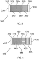
- FIG. 3 One illustration is shown in FIG. 3 .
- the device 300 comprises a body 310. When sampling, the sample enters the sampling inlet 320. The components are adsorbed onto the adsorbents, and unretained material exits the tube through sampling outlet 330. Disposed internally in a cavity of the body 310 is a first sorbent material 340, a second sorbent material 350 and a third sorbent material 360. The first sorbent material 340, the second sorbent material 350 and the third sorbent material 360 can be separated from each other by fluid permeable barriers 365 and 370.
- the fluid permeable barriers 365 and 370 can be any suitable material that permits diffusion of a fluid from one portion of the sorbent device, through the barrier and onto another portion of the sorbent device. In this tube design, a thin mesh screen is used; however, glass frits or other fluid permeable barrier can also be used. Illustrative fluid permeable barriers include those described herein. Barrier or clips 375 and 380 can be used to keep the sorbent materials 340, 350 and 360 in the body 310 of the sorbent device 300.
- the tube 300 is inserted into the carrier stream and species desorb and elute in a reverse direction from which they were sampled; an inert gas is introduced into the sampling outlet (or desorption inlet) 330, and as species desorb from the sorbent materials 340, 350 and 360, the desorbed species exit the sorbent device 300 through the sampling inlet (or desorption outlet) 320, which is typically in fluid communication with a fluid line in a gas chromatography system or other analytical device.
- the sorbent materials can be packaged into the sorbent device in a selected order.
- the stronger sorbents are packed adjacent to the sampling outlet, and weaker sorbent materials are packed against the stronger sorbent materials in serial fashion according to their relative ability to adsorb species.
- Such packing permit sampling in the direction of weakest to strongest sorbent material and permits analysis in the direction from strongest to weakest sorbent material.
- the terms stronger and weaker are relative terms, and the adsorption strength and desorption efficiency are functions of surface area, pore size(s) and shape(s), pore volume and surface chemistry of the sorbent materials. No absolute strength is required, rather the various materials that are used are stronger or weaker adsorbers relative to another material.
- sorbent materials may be selected to increase the probability that all species adsorb and then desorb from the sorbent device. For example, it is desirable to leave sites in the stronger sorbent material to be available to adsorb the lighter components. In addition, if the higher molecular weight analytes become adsorbed to the stronger or strongest sorbent material, they may not desorb. By sampling in one direction and desorbing in the opposite direction, the higher molecular weight materials do not occupy or enter into the stronger sorbent materials, which increases the likelihood that they will fully desorb from the sorbent device.
- the sorbent device includes four different sorbent materials each separated by a fluid permeable barrier. An illustration of such is shown in FIG. 4 .
- the device 400 comprises a body 410, a sampling inlet 420, and a sampling outlet 430. Disposed internally in a cavity of the body 410 is a first sorbent material 440, a second sorbent material 445, a third sorbent material 450 and a fourth sorbent material 455.
- the first sorbent material 440, the second sorbent material 445, the third sorbent material 450 and the fourth sorbent material 455 can be separated from each other by fluid permeable barriers 460, 465 and 470.
- the first sorbent material 440 can be a weak sorbent material such that lighter analytes break through and heavier analytes are adsorbed.
- the second sorbent material 445 can be a stronger sorbent material than the first sorbent material 440 and a weaker sorbent material than the third sorbent material 450.
- the fourth sorbent material 455 can be the strongest of the sorbent materials in the sorbent device 400.
- the fluid permeable barriers 460, 465 and 470 can be any suitable material that permits diffusion of a fluid from one portion of the sorbent device, through the barrier and onto another portion of the sorbent device.
- a thin mesh screen is used; however, it may be a glass frit, a coated stainless steel mesh or other suitable fluid permeable barriers.
- Illustrative fluid permeable barriers include those described herein. Barriers or clips 475 and 480 can be used to keep the sorbent materials 440, 445, 450 and 455 in the body 410 of the sorbent device 400.
- the tube 400 is inserted into the flow path in the reverse direction that it was sampled by introducing an inert gas into the desorption inlet (or sampling outlet) 430, and as species desorb from the sorbent material 440, 445, 450 and 455, the desorbed species exit the sorbent device 400 through the desorption outlet (or sampling inlet) 420, which is typically in fluid communication with a fluid line in a gas chromatography system or other analytical device.
- more than four materials can be used in a sorbent device.
- the number of sorbent materials used in the sorbent devices can vary depending on the number of analytes and the types of analytes suspected to be present. Where the number and type of analytes are unknown, a sorbent device including a plurality of different types of sorbent materials can be used to ensure that substantially all of the analytes can be analyzed.
- the sorbent materials can be arranged from weakest to strongest with the weakest sorbent material being closest to the sampling inlet and the strongest sorbent material being closest to the sampling outlet.
- FIGS. 2-4 show the various sorbent material areas as being substantially the same, it may be desirable to include a particular sorbent material in a larger amount that the other sorbent materials.
- the sorbent material effective to adsorb and desorb that analyte may be present in a larger amount/volume to provide for increased loading of that analyte.
- the sorbent materials can each be present at substantially the same weight ratio, e.g., 1:1.
- the different sorbent materials can independently be present in weight ratios ranging from 3:1, 2.5:1, 2:1, 1.5:1, 1.1:1, 0.9:1, 0.8:1, 0.7:1, 0.6:1, 0.5:1, 0.4:1, 0.3:1, 0.2:1, 0.1:1 or any ratio in between these illustrative ratios. It may be desirable to determine the relative weight ratios using the first sorbent material (the one closest to the sampling inlet) as the normalization factor, and the amount of each of the other sorbent materials that is present can be divided by the amount of the first sorbent material that is present to determine the relative weight ratios present in the sorbent device.
- sorbent device In some examples where a four bed sorbent device is used, about 1.4 to 0.6 of the first sorbent material, 1.54 to 0.56 of the second sorbent material, 1.92 to 0.82 of the third sorbent material and 1.5 to 0.64 of the fourth sorbent material may be present in the sorbent device. Additional suitable amounts of the sorbent materials will be readily selected by the person of ordinary skill in the art, given the benefit of this disclosure.
- the invention includes a combination of sorbent materials based on a combination of graphitized carbon blacks and a carbon molecular sieve.
- the sorbent material may be based on a mixture of graphitized carbon blacks of different strengths.
- the different sorbent material in the sorbent devices may have a different chemical composition.
- the sorbent material may be a derivatized form.
- the graphitized carbon black can be for example, CarbotrapTM B sorbent or CarbopackTM B sorbent, CarbotrapTM Z sorbent or CarbopackTM Z sorbent, CarbotrapTM C sorbent or CarbopackTM C sorbent, CarbotrapTM X sorbent or CarbopackTM X sorbent, CarbotrapTM Y sorbent or CarbopackTM Y sorbent, CarbotrapTM F sorbent or CarbopackTM F sorbent, any one or more of which may be used in its commercial form (available commercially from Supelco or Sigma-Aldrich) or may be graphitized according to known protocols.
- CarbotrapTM B sorbent or CarbopackTM B sorbent for example, CarbotrapTM B sorbent or CarbopackTM B sorbent, CarbotrapTM Z sorbent or CarbopackTM Z sorbent, CarbotrapTM C sorbent or CarbopackTM C sorbent, CarbotrapTM
- the carbon molecular sieves can be CarboxenTM 1000 sorbent, CarboxenTM 1003 sorbent, or CarboxenTM-1016 sorbent, any one or more of which may be used in its commercial form (available commercially from Supelco or Sigma-Aldrich) or may be optimized according to known protocols.
- each of the sorbent materials may be one of the sorbent materials listed in this paragraph with each of the sorbent materials being a different sorbent material than the other sorbent materials used in the sorbent device. In such instances, four different sorbent materials would be present in the sorbent device.
- the mesh size or range of the sorbent can vary depending on the particular material selected. In some examples, the mesh size can range from 20 to about 100, more particular from about 20-80, 30-70 or 40-60. In other examples, the mesh size range may be from about 20-40, 40-60, 60-80 or 80-100 depending on the material used in the sorbent devices. Other suitable mesh sizes will be readily selected by the person of ordinary skill in the art, given the benefit of this disclosure.
- the body of the sorbent device may be made from, or include, many different types of materials.
- quartz, stainless steel, coated stainless steel or other metal or non-metal based materials that can tolerate the temperature cycles used to desorb the analytes can be used.
- the sorbent devices described herein can be produced by disposing a suitable type and amount of sorbent material in a body.
- a suitable type and amount of sorbent material for example, one end of a hollow stainless steel tube can be equipped with a stationary screen to retain the first sorbent material in the tube.
- a first sorbent material can be disposed in the tube.
- a second fluid permeable barrier can be placed on or in the disposed first sorbent material, and a second sorbent material can then be disposed on the second fluid permeable barrier. This process can be repeated until a desired number of sorbent materials are present in the tube.
- a fluid permeable barrier can be placed against it and a clip can be inserted to hold the adsorbents in place. In this configuration, the sorbent materials are held in place on one end by a stationary fluid permeable barrier and on the other end by a clip.
- Other similar retention devices can be used to hold the sorbents in the body of the sorbent device.
- the integrity of the device can be assessed prior to use.
- internal voids may form that can affect the quality of the tubes.
- the quality of the desorption tubes can be assessed as described in commonly assigned issued patent bearing patent number U.S. 7,422,625 , to ensure there are no undesirable voids or features in the sorbent device.
- the sorbent devices described herein can be used with automated thermal desorption (ATD) gas chromatography system.
- ATD works by heating the sorbent device for a required amount of time to release volatiles from the sorbent material.
- a carrier gas such as helium, nitrogen or hydrogen flows through the tube at a desired flow rate to transfer the contents of the sorbent tube onto a cooled secondary trap via a carrier gas, which is typically helium or hydrogen.
- This trap is then rapidly heated to desorb the collected components in a narrow band into the GC column for separation.
- a mass spectrometer is the most common detector used to provide the analysis. The information is sent to a computer containing an application which sends information to the instrument for control and collects information from the detector for analysis. This application has the ability to process this information which can provide quantitative and qualitative results.
- a single desorption cycle can be used to desorb substantially all adsorbed species. Such desorption typically permits reuse of the sorbent device without further temperature treatment, e.g., baking for extended periods, to remove high molecular weight species.
- the sorbent devices described herein may be particularly advantageous for use where it is desirable to continuously monitor the air quality in an air space occupied by animals such as humans.
- the reusability of the sorbent devices permits automated monitoring without having to change out the tube.
- air may be periodically sampled in an airplane cabin, cockpit, spacecraft cabin, space station or the like for the presence of volatile species that may lead to adverse health effects.
- a single sorbent device can be used repeatedly.
- the ability to reuse the same tube without having to subject the tube to high temperatures permits their use in these applications and others including, but not limited to, repetitive air space sampling of foreign body atmospheres, e.g., moons, planets, and other applications where it may not be feasible to heat the tubes for extended periods prior to reuse.
- the sorbent devices described herein can be used with one or more instruments that are controlled or otherwise operated by, at least in part, a computer system.
- An illustrative system is shown in FIG. 5 .
- the system 500 includes a carrier gas supply 510 fluidically coupled to a sorbent device 520, which may any of those described herein. Suitable valving or other devices may be present in the system to permit or restrict fluid flow between the carrier gas supply 510 and the sorbent device 520, depending on the desired flow of the carrier gas.
- an injector may also be fluidically coupled to the sorbent device 520 and/or carrier gas supply 510, if desired.
- the sorbent device 520 is fluidically coupled to a column 530, which is effective to separate species based on their partitioning between the mobile phase and the column's stationary phase. Species that elute from the column 530 are provided to a detector 540, which can analyze those species based on chemical or physical properties.
- the detector can be any of those detectors commonly used in gas chromatographic systems including, but not limited to, a mass spectrometer, a flame ionization detector, a thermal conductivity detector, a thermionic detector, an electron-capture detector, a discharge ionization detector, a Hall electrolytic conductivity detector, an atomic emission detector, a flame photometric detector, a pulsed discharge ionization detector, a photoionization detector and other suitable types of detectors.
- the system 500 can include a computer system with a user interface such that a user may enter starting and final temperatures, temperature ramp parameters, sorbent device materials, and the like for use by the computer system in quantifying the analytes adsorbed to the sorbent devices.
- the sorbent devices described herein can be used with a swafer device such as those described in commonly assigned U.S. Patent Application No. 12/472,948 filed on May 27, 2009 (now US Patent 8,303,694 ).
- the carrier gas supply 510 and the sorbent device 520 can be fluidically coupled to different ports of the swafer device.
- Certain embodiments of the sorbent devices described herein can provide numerous advantages including, but not limited to, the adsorption of the most volatile analytes (the gases) within acceptable break through limits while increasing sampling volumes to ensure detection limits are met and/or exceeded.
- the gases most volatile analytes
- Currently available tubes do not retain these volatile compounds and suffer from significant breakthrough of these compounds - as high as 60% sampling a 1 liter volume and as high as 80% sampling 10 liter volumes.
- Embodiments of the sorbent devices described herein can also provide excellent recovery (quantitative accuracy) of analytes because they are thermally desorbed from the tube during the tube desorb step which allows the analytes to be quantitatively introduced into the analytical system.
- examples of the sorbent devices described herein can desorb analytes in a single desorption cycle to increase laboratory productivity and reduce costs rendering sampling financially feasible, because the tube is immediately available for re-sampling.
- Current tubes not only have poor recoveries of these analytes, but they are typically baked, at times for 10 hours, to rid the tube of these higher boiling point compounds, which reduces productivity and increases the cost per sample.
- a sorbent device was produced using eight different sorbent materials. These sorbent materials were: graphitized carbon blacks such as CarboTrapTM or CarboPackTM F, C, Y, B, Z and X sorbents and carbon molecular sieves such as CarboxenTM 1000, 1016 and specially treated carboxens.
- the sorbent devices were generally constructed as follows: An empty tube provided by PerkinElmer (part L427-0128) that contained a fixed fluid permeable membrane on one end was used. This end was the sampling end of the tube. The weakest adsorbent, CarboTrapTM F or CarboPackTM F sorbent was packed first into the tube using a funnel. The tube was tapped to ensure channeling of the adsorbent did not occur. A fluid permeable membrane, in this case, a stainless steel mesh from PerkinElmer (part # L407-1034) was inserted into the tube and lightly pressed against sorbent F.
- a sorbent device was produced according to the protocol listed in Example 1. This device was specifically designed for soil vapor intrusion measurements, but not limited to this application.
- the sorbent device included the following types of sorbent materials (in order from the sampling inlet side of the tube to the sampling outlet side of the tube): CarbotrapTM F sorbent, CarbotrapTM Y sorbent, CarbotrapTM X sorbent and a carboxen sorbent material.
- This tube design provides excellent retention of the gases in addition to significantly extending the molecular weight range through diesel which is required in soil vapor samples.
- a sorbent device was produced according to the protocol listed in Example 1. This device was designed for the analysis where the gases in US EPA Methods TO-15/TO-17 target analytes are not required specifically dichlorodifluoromethane, chloromethane, vinyl chloride, bromomethane, chloroethane, and trichlorofluoromethane.
- the advantage is when the strongest adsorbent is eliminated the tubes are significantly more hydrophobic requiring less dry purge time and faster analysis.
- a larger bed of weaker adsorbent may be used to decrease desorption times.
- the sorbent device included the following types of sorbent materials (in order from the sampling inlet side of the tube to the sampling outlet side of the tube): Carbotrap FTM sorbent, Carbotrap YTM sorbent, and Carbotrap XTM sorbent.
- a sorbent device was produced according to the protocol listed in Example 1. This device was designed for when the site has less higher molecular weight species (or larger molecules) and significantly more mid-range targets requiring additional stronger sorbent material. This tube replaces the CarbotrapTM Y sorbent or CarbopackTM Y sorbent in Example 2 with CarbotrapTM B sorbent or CarbopackTM B sorbent, which is a stronger adsorbent.
- the sorbent device included the following types of sorbent materials (in order from the sampling inlet side of the tube to the sampling outlet side of the tube): CarbotrapTM F sorbent or CarbopackTM F sorbent, CarbotrapTM B sorbent or CarbopackTM B sorbent, CarbotrapTM X sorbent or CarbopackTM X sorbent and a CarboxenTM sorbent.
- Tubes made according to Example 2 were spiked with a very concentrated standard, 25.6 micrograms total of 86 target analytes plus 10 micrograms of diesel. The 86 components are listed in Table I shown in FIG. 6 .
- a schematic of the tube is shown in FIG. 7 . From left to right (sampling inlet 720 to sampling outlet 730), the tube included CarbotrapTM F sorbent (20/40 mesh), CarbotrapTM Y sorbent (20/40 mesh), CarbotrapTM X sorbent (20/40 mesh) and CarboxenTM sorbent (60/80 mesh) About 1-2 mm of open space was present at the sampling outlet end of the tube. A clip or retaining spring 710 was inserted following the strongest adsorbent to secure the bed.
- the sampling inlet 720 included a stationary fluid permeable membrane 705 to retain the sorbent material.
- Stainless steel meshes 740, 750 and 760 were used to separate the different sorbent materials.
- the relative weight range of each material could vary as follows: 1.4 to 0.6 of CarbotrapTM F sorbent, 1.54 to 0.56 of CarbotrapTM Y sorbent, 1.92 to 0.82 of CarbotrapTM X sorbent and 1.5 to 0.64 of Carboxen sorbent normalized to weakest adsorbent weight.
- Break through, recovery (carryover), precision, linearity, reporting limit, and minimum detectable limit (mdl) studies were performed as follows: tubes were spiked with the very concentrated standard, 25.6 micrograms total of the 86 target analytes in Table I plus 10 micrograms of diesel.
- a clean tube (referred to below as a "break through tube") containing CarbotrapTM X sorbent and a CarboxenTM sorbent was connected to the spiked tube to determine breakthrough using the apparatus shown in FIG. 8 , with the arrows in FIG. 8 showing the direction of carrier gas flow.
- the apparatus 800 included an injector 810 fluidically coupled to a nitrogen carrier gas.
- the nitrogen carrier gas was humidified by providing the nitrogen gas to a water reservoir 820 through a fluid line 815.
- the carrier gas is provided to a spiked tube 830 that included the analytes.
- the spiked tube was fluidically coupled to a clean tube 840.
- the tubes were placed on a manifold with 100 milliliters/minute of humidified (70%) nitrogen for 100 minutes to represent a 10 liter sampling volume.
- the spiked tube was analyzed again to determine if there were any analytes remaining on the spiked tube.
- the 86 analytes spiked onto the tube at a concentration of 300 nanograms/analyte, and 10 micrograms of diesel, there was slight carryover of the heaviest component phenanthrene at 1%.
- the diesel carryover was less than 1%.
- FIGS. 9A-11B graphically demonstrate the recovery of analytes from this heavily concentrated spiked tube using one desorption cycle.
- the top chromatogram is the spiked tube and the bottom chromatogram is the reinjection of this spiked tube which is used to determine if there was complete desorption of the spiked tube (top chromatogram) from one desorption cycle.
- FIGS. 9A and 9B represent what is referred to as the Total Ion Chromatogram or the TIC which displays all the masses collected in that acquisition.
- FIGS. 10A and 10B represent the same injections as FIG. 9A and 9B , respectively; however, the display is what is called a mass chromatogram of ion 57. Mass 57 is a representative ion in diesel.
- FIGS. 11A and 11B displays the same injection as FIG. 9A and 9B , respectively; however, the display is the mass chromatogram of the sum of the heaviest PAHs, mass 142 methyl naphthalene; mass 166 fluorene; mass 153 anthracene and mass 178 phenanthrene. Since diesel and these PAHs represent the heaviest components in the mix, the mass chromatograms were use instead of the TIC to rigorously demonstrate the desorption in one cycle of the heaviest components which are the most difficult to desorb.
Landscapes
- Chemical & Material Sciences (AREA)
- Analytical Chemistry (AREA)
- Chemical Kinetics & Catalysis (AREA)
- Organic Chemistry (AREA)
- Engineering & Computer Science (AREA)
- Inorganic Chemistry (AREA)
- General Chemical & Material Sciences (AREA)
- Oil, Petroleum & Natural Gas (AREA)
- Materials Engineering (AREA)
- Sampling And Sample Adjustment (AREA)
- Separation Of Gases By Adsorption (AREA)
- Solid-Sorbent Or Filter-Aiding Compositions (AREA)
Claims (7)
- Dispositif sorbant permettant de détecter une quantité de composés organiques volatiles dans un échantillon d'air, le dispositif sorbant comprenant :un corps comprenant une entrée d'échantillonnage, une sortie d'échantillonnage et une cavité située entre l'entrée et la sortie ;la cavité comprenant un agencement sériel de quatre matières sorbantes différentes, chacune efficace pour adsorber et désorber un ou plusieurs des composés organiques volatiles de l'échantillon d'air, les matières sorbantes étant agencées en partant d'une matière présentant le pouvoir sorbant le plus faible jusqu'à une matière présentant le pouvoir sorbant le plus fort, eu égard à leur aptitude relative à adsorber les composés organiques volatiles,la matière présentant le pouvoir sorbant le plus faible étant efficace pour adsorber et désorber des composés organiques volatiles à haut point d'ébullition, et la matière présentant le pouvoir sorbant le plus fort étant efficace pour adsorber et désorber des composés et gaz organiques volatiles de faible poids qui percent la matière de moindre pouvoir sorbant,la matière au pouvoir sorbant le plus faible étant adjacente à l'entrée d'échantillonnage,le dispositif sorbant comprenant en outre une barrière perméable aux fluides entre chacune des quatre matières sorbantes différentes ;trois des quatre matières sorbantes différentes étant un noir de carbone graphitisé, chacune des trois matières sorbantes consistant en du noir de carbone graphitisé ayant une composition chimique différente ;l'une des quatre matières sorbantes différentes étant un tamis moléculaire de carbone ;les quatre matières sorbantes différentes étant efficaces pour désorber sensiblement tous les composés organiques volatiles adsorbés sur les quatre matières sorbantes différentes en un cycle de désorption unique, et le dispositif sorbant pouvant être réutilisé sans aucune étape de traitement thermique après ledit cycle de désorption unique.
- Dispositif selon la revendication 1, dans lequel la barrière perméable aux fluides comprend un filet en acier.
- Dispositif selon la revendication 1, dans lequel l'une des trois matières sorbantes consistant en du noir de carbone graphitisé est à base d'un mélange de noirs de carbone graphitisés de différentes forces.
- Dispositif selon la revendication 1, lequel est efficace pour adsorber et désorber des composés organiques volatiles de l'échantillon d'air comprenant lesdits composés organiques volatiles, le dispositif sorbant étant un tube creux, et dans lequel les quatre matières sorbantes différentes sont agencées en série dans la cavité du tube creux en partant d'une matière présentant le pouvoir sorbant le plus faible jusqu'à une matière présentant le pouvoir sorbant le plus fort, la matière au pouvoir sorbant le plus faible étant adjacente à l'entrée du tube creux et la matière au pouvoir sorbant le plus fort adjacente à la sortie du tube creux.
- Dispositif selon la revendication 4, dans lequel l'une des trois matières sorbantes consistant en du noir de carbone graphitisé est à base d'un mélange de noirs de carbone graphitisés de différentes forces.
- Procédé comprenant :l'exposition du dispositif sorbant selon la revendication 1 à l'échantillon d'air comprenant les composés organiques volatiles pour permettre aux composés organiques volatiles d'être adsorbés sur les matières sorbantes du dispositif sorbant ; etla désorption des composés organiques volatiles adsorbés sur les matières sorbantes du dispositif sorbant au moyen d'un seul cycle de désorption pour désorber tous les composés organiques volatiles adsorbés dans le dispositif sorbant.
- Dispositif selon la revendication 6, comprenant en outre la réutilisation du dispositif sorbant pour permettre l'adsorption des composés organiques volatiles sur les matières sorbantes du dispositif sorbant sans aucune étape de traitement thermique supplémentaire visant à éliminer les composés organiques volatiles adsorbés résiduels préalablement à la réutilisation du dispositif sorbant.
Applications Claiming Priority (2)
| Application Number | Priority Date | Filing Date | Title |
|---|---|---|---|
| US12/573,048 US8388736B2 (en) | 2009-10-02 | 2009-10-02 | Sorbent devices and methods of using them |
| PCT/US2010/050828 WO2011041486A1 (fr) | 2009-10-02 | 2010-09-30 | Dispositifs sorbants et procédés d'utilisation de ces dispositifs |
Publications (3)
| Publication Number | Publication Date |
|---|---|
| EP2482969A1 EP2482969A1 (fr) | 2012-08-08 |
| EP2482969A4 EP2482969A4 (fr) | 2016-10-19 |
| EP2482969B1 true EP2482969B1 (fr) | 2021-01-06 |
Family
ID=43822175
Family Applications (1)
| Application Number | Title | Priority Date | Filing Date |
|---|---|---|---|
| EP10821215.0A Not-in-force EP2482969B1 (fr) | 2009-10-02 | 2010-09-30 | Dispositifs sorbants et procédés d'utilisation de ces dispositifs |
Country Status (6)
| Country | Link |
|---|---|
| US (3) | US8388736B2 (fr) |
| EP (1) | EP2482969B1 (fr) |
| CN (1) | CN202655038U (fr) |
| AU (2) | AU2010300619B2 (fr) |
| CA (1) | CA2775896C (fr) |
| WO (1) | WO2011041486A1 (fr) |
Families Citing this family (46)
| Publication number | Priority date | Publication date | Assignee | Title |
|---|---|---|---|---|
| CN202822862U (zh) * | 2008-05-27 | 2013-03-27 | 魄金莱默保健科学有限公司 | 色谱系统 |
| EP2411782B1 (fr) * | 2009-03-24 | 2019-01-30 | PerkinElmer Health Sciences, Inc. | Dispositifs sorbants dotés de trajets de diffusion longitudinaux et leurs procédés d'utilisation |
| US8388736B2 (en) | 2009-10-02 | 2013-03-05 | Perkinelmer Health Sciences, Inc. | Sorbent devices and methods of using them |
| US8157892B2 (en) | 2010-05-17 | 2012-04-17 | Enverid Systems, Inc. | Method and system for improved-efficiency air-conditioning |
| AU2011267964B2 (en) | 2010-06-14 | 2015-07-09 | Perkinelmer U.S. Llc | Fluidic devices and methods of using them |
| CN203935755U (zh) | 2010-09-22 | 2014-11-12 | 魄金莱默保健科学有限公司 | 用于色谱的反冲系统和装置 |
| US20120186366A1 (en) * | 2011-01-26 | 2012-07-26 | Energy & Environmental Research Center | Measurement of multimetals and total halogens in a gas stream |
| US8690999B2 (en) | 2011-02-09 | 2014-04-08 | Enverid Systems, Inc. | Modular, high-throughput air treatment system |
| JP2014522298A (ja) | 2011-05-17 | 2014-09-04 | エンベリッド システムズ, インコーポレイテッド | 屋内空気からの二酸化炭素の低減のための収着剤 |
| US9316410B2 (en) | 2011-11-17 | 2016-04-19 | Enverid Systems, Inc. | Method and system for conditioning air in an enclosed environment with distributed air circulation systems |
| WO2013106573A1 (fr) | 2012-01-10 | 2013-07-18 | Enverid Systems, Inc | Procédés et systèmes de gestion de la qualité de l'air et de l'utilisation de l'énergie dans des systèmes de conditionnement d'air |
| US9802154B2 (en) | 2012-03-30 | 2017-10-31 | Fuel Tech, Inc. | Process for sulfur dioxide, hydrochloric acid and mercury mediation |
| US8992868B2 (en) * | 2012-05-01 | 2015-03-31 | Fuel Tech, Inc. | Dry processes, apparatus compositions and systems for reducing mercury, sulfur oxides and HCl |
| CN108096991A (zh) * | 2012-05-22 | 2018-06-01 | 恩沃德系统公司 | 对室内空气的洗涤的吸附剂的高效利用 |
| JP2015528743A (ja) | 2012-07-18 | 2015-10-01 | エンベリッド システムズ, インコーポレイテッド | 屋内空気清浄のための再生吸収剤 |
| US9399187B2 (en) | 2012-09-24 | 2016-07-26 | Enverid Systems, Inc. | Air handling system with integrated air treatment |
| CN104797323B (zh) | 2012-11-15 | 2017-11-14 | 恩沃德系统公司 | 适用于减少室内空气中的有害气体的方法和系统 |
| US9289721B2 (en) | 2013-02-27 | 2016-03-22 | Fuel Tech, Inc. | Process and apparatus for improving the operation of wet scrubbers |
| CA2902909C (fr) | 2013-02-27 | 2017-11-28 | Fuel Tech, Inc. | Procedes, appareil, compositions et systemes permettant de reduire des emissions de hcl et/ou d'oxydes de soufre |
| US9718025B2 (en) | 2013-04-01 | 2017-08-01 | Fuel Tech, Inc. | Reducing hydrochloric acid in cement kilns |
| US9399597B2 (en) | 2013-04-01 | 2016-07-26 | Fuel Tech, Inc. | Ash compositions recovered from coal combustion gases having reduced emissions of HCI and/or mercury |
| US9919257B2 (en) | 2013-09-17 | 2018-03-20 | Enverid Systems, Inc. | Systems and methods for efficient heating of sorbents in an indoor air scrubber |
| US11458451B2 (en) | 2015-04-24 | 2022-10-04 | Xplosafe, Llc | Sorbent and devices for capturing, stabilizing and recovering volatile and semi-volatile compounds |
| US10365075B2 (en) | 2015-04-24 | 2019-07-30 | Xplosafe, Llc | Explosive-containing porous materials as non-detonable training aid |
| US10866166B2 (en) | 2018-07-25 | 2020-12-15 | Xplosafe, Llc | Sorbent and devices for capturing, stabilizing and recovering volatile and semi-volatile compounds |
| US11964252B2 (en) * | 2015-04-24 | 2024-04-23 | Xplosafe, Llc | Sorbent and devices for capturing, stabilizing, and recovering volatile and semi-volatile compounds |
| WO2016183237A1 (fr) | 2015-05-11 | 2016-11-17 | Enverid Systems, Inc. | Procédé et système de réduction des gaz indésirables dans l'air intérieur |
| CN209194072U (zh) | 2015-06-30 | 2019-08-02 | 珀金埃尔默健康科学股份有限公司 | 气相色谱系统 |
| WO2017035254A1 (fr) | 2015-08-24 | 2017-03-02 | Enverid Systems, Inc. | Épurateur pour système de chauffage, ventilation et climatisation |
| US11207633B2 (en) | 2016-04-19 | 2021-12-28 | Enverid Systems, Inc. | Systems and methods for closed-loop heating and regeneration of sorbents |
| US11110387B2 (en) | 2016-11-10 | 2021-09-07 | Enverid Systems, Inc. | Low noise, ceiling mounted indoor air scrubber |
| CN106568876A (zh) * | 2016-11-16 | 2017-04-19 | 上海化工研究院 | 一种多级贯流吸附式用于气质联用‑顶空分析采样装置 |
| US20180252619A1 (en) * | 2017-03-06 | 2018-09-06 | Beacon Environmental Services, Inc. | Environmental sampling apparatuses, systems, and related methods |
| US11549921B2 (en) | 2017-11-22 | 2023-01-10 | Entech Instruments Inc. | System and method for real time monitoring of a chemical sample |
| WO2019104226A1 (fr) | 2017-11-22 | 2019-05-31 | Entech Instruments Inc. | Système et procédé de surveillance en temps réel d'un échantillon chimique |
| CN108152219A (zh) * | 2017-12-29 | 2018-06-12 | 亚申科技研发中心(上海)有限公司 | 合成气中杂质的实时检测方法及装置 |
| CN108452635B (zh) * | 2018-02-09 | 2020-12-04 | 北京东方计量测试研究所 | 优化VOCs吸附材料组合配方的方法 |
| US11896366B2 (en) | 2018-03-06 | 2024-02-13 | Entech Instruments Inc. | Ventilator-coupled sampling device and method |
| CN108801713A (zh) * | 2018-03-29 | 2018-11-13 | 复旦大学 | 一种实现大气放射性氚碳被动联合采集的装置 |
| US12158454B2 (en) | 2018-07-31 | 2024-12-03 | Entech Instruments Inc. | Hybrid capillary/packed trap and method of use |
| US11179233B2 (en) * | 2018-08-02 | 2021-11-23 | Perkinelmer Health Sciences, Inc. | Staging assembly for specimen imaging system |
| WO2020252231A1 (fr) * | 2019-06-14 | 2020-12-17 | Chevron U.S.A. Inc. | Systèmes et procédés d'échantillonnage d'espèces chimiques dans divers environnements |
| US11946912B2 (en) | 2020-06-30 | 2024-04-02 | Entech Instruments Inc. | System and method of trace-level analysis of chemical compounds |
| CN116194752A (zh) | 2020-08-11 | 2023-05-30 | 因泰科设备股份有限公司 | 用于在gcms分析之前改进样品制备的基质加速真空辅助吸附剂萃取的系统和方法 |
| JP2024519913A (ja) * | 2021-05-18 | 2024-05-21 | ダブリュ.エル.ゴア アンド アソシエイツ,インコーポレイティド | 選択的バリア層を備えた収着性物品 |
| EP4207215A1 (fr) * | 2021-12-31 | 2023-07-05 | Sck.Cen | Génération de radionucléides |
Family Cites Families (44)
| Publication number | Priority date | Publication date | Assignee | Title |
|---|---|---|---|---|
| US1789194A (en) * | 1925-03-20 | 1931-01-13 | Paul O Rockwell | Process and apparatus for purifying air |
| US2798718A (en) * | 1951-10-26 | 1957-07-09 | William E Gross | Canister spring |
| US5661224A (en) * | 1996-02-08 | 1997-08-26 | H2M Labs, Inc. | Method and apparatus for spiking atmospheric samples |
| US5933357A (en) | 1996-09-13 | 1999-08-03 | The Perkin-Elmer Corporation | Backflushing system for gas chromatography |
| US5958246A (en) | 1997-05-16 | 1999-09-28 | The Perkin-Elmer Corporation | Standardization of chromatographic systems |
| US6074459A (en) * | 1998-01-05 | 2000-06-13 | Uop Llc | Ultra pure gases: removal of halocarbons, fluorocarbons, and sulfur compounds from gas streams |
| WO2000045929A1 (fr) | 1999-02-08 | 2000-08-10 | Admetric Biochem Inc. | Systeme de chromatographie avec commutation d'eluants en amont du detecteur |
| US6511528B1 (en) * | 1999-03-26 | 2003-01-28 | Uop Llc | Purification of carbon dioxide |
| US6494939B1 (en) | 1999-09-16 | 2002-12-17 | Perkinelmer Instruments Llc | Zero-dilution split injector liner gas chromatography |
| US7013707B2 (en) | 1999-11-19 | 2006-03-21 | Perkinelmer Las, Inc | Method and apparatus for enhanced detection of a specie using a gas chromatograph |
| FR2804042B1 (fr) | 2000-01-25 | 2002-07-12 | Air Liquide | Procede de purification d'un gaz par adsorption des impuretes sur plusieurs charbons actifs |
| JP3917938B2 (ja) | 2000-11-28 | 2007-05-23 | エムディーエス インコーポレイテッド | 複数の並行した液体試料流を同期させる高速流体システムを用いた質量分析用試料導入装置 |
| US7008470B2 (en) * | 2000-12-25 | 2006-03-07 | Aisan Kogyo Kabushiki Kaisha | Canister |
| TW469497B (en) | 2001-02-27 | 2001-12-21 | Jiun-Guang Luo | Sampling apparatus of environmental volatile organic compound for semiconductor operation |
| DE10113414C2 (de) | 2001-03-20 | 2003-04-24 | Fette Wilhelm Gmbh | Vorrichtung zum Aussortieren von Tabletten in einer Rundläufer-Tablettenpresse |
| US20020187483A1 (en) * | 2001-04-20 | 2002-12-12 | Cerner Corporation | Computer system for providing information about the risk of an atypical clinical event based upon genetic information |
| KR20030051281A (ko) | 2001-12-14 | 2003-06-25 | 후지 샤신 필름 가부시기가이샤 | 자기전사용 마스터 담체 |
| US6645773B2 (en) | 2002-02-20 | 2003-11-11 | Perkinelmer Instruments Llc | Method for measuring effective temperature inside a sealed container |
| CN100354024C (zh) * | 2002-05-31 | 2007-12-12 | 普莱克斯技术有限公司 | 高纯度和超高纯度气体的生产 |
| US6652625B1 (en) | 2002-07-24 | 2003-11-25 | Perkin Elmer Instruments Llc | Analyte pre-concentrator for gas chromatography |
| US6814785B2 (en) | 2002-07-24 | 2004-11-09 | Perkinelmer Instruments Llc | Analyte pre-concentrator for gas chromatography |
| ES2455992T3 (es) * | 2002-12-24 | 2014-04-21 | Praxair Technology, Inc. | Procedimiento y aparato para la purificación de hidrógeno |
| JP4018737B2 (ja) | 2003-04-14 | 2007-12-05 | パーキンエルマー・エルエーエス・インコーポレーテッド | ヘッドスペース蒸気を抽出するためのシステムおよび方法 |
| US8182768B2 (en) | 2003-04-14 | 2012-05-22 | Perkinelmer Las, Inc. | Interface assembly for pre-concentrating analytes in chromatography |
| JP2006526154A (ja) | 2003-05-23 | 2006-11-16 | パーキンエルマー・エルエーエス・インコーポレーテッド | 熱脱離用サンプリングチューブの完全性を検証するための方法 |
| ATE386265T1 (de) | 2003-10-17 | 2008-03-15 | Perkinelmer Las Inc | Verfahren zur einführung von standardgas in ein probengefäss |
| WO2005040786A2 (fr) | 2003-10-23 | 2005-05-06 | Perkinelmer Life And Analytical Sciences | Preconcentrateur d'analyte comportant un ecoulement d'adsorption de sortie separe et un ecoulement d'entree de desorption |
| US20050180893A1 (en) | 2004-02-17 | 2005-08-18 | Handly Robert A. | Centerless ground thermal desorption tube and method without frit |
| US7111494B2 (en) | 2004-03-04 | 2006-09-26 | Perkinelmer Las, Inc. | Methods and systems for characterizing a sorbent tube |
| WO2005100254A2 (fr) | 2004-04-19 | 2005-10-27 | Glass Plus, Llc | Procede et dispositif pour l'elimination de pollutions par les hydrocarbures et l'extinction d'incendies |
| AU2005259865B2 (en) | 2004-06-29 | 2009-11-26 | Perkinelmer Las, Inc. | Interface from a thermal desorption unit to a chromatographic column |
| US7219532B2 (en) | 2004-07-26 | 2007-05-22 | Perkinelmer Las, Inc. | System for regulating fluid flowing through chromatographic column |
| GB0419419D0 (en) | 2004-09-01 | 2004-10-06 | Medical Res Council | Method |
| US7468095B2 (en) | 2005-05-12 | 2008-12-23 | Perkinelmer Las, Inc. | System for controlling flow into chromatographic column using transfer line impedance |
| JP4699520B2 (ja) | 2005-06-14 | 2011-06-15 | パーキンエルマー・ヘルス・サイエンシズ・インコーポレーテッド | クロマトグラフカラムを冷却する方法 |
| US7381244B2 (en) * | 2005-08-03 | 2008-06-03 | Air Products And Chemicals, Inc. | Apparatus and process for air cleaning |
| ES2628614T3 (es) | 2006-08-18 | 2017-08-03 | Perkinelmer, Inc. | Dispositivos para hacer circular aire en un sistema de cromatografía de gases |
| CN202822862U (zh) | 2008-05-27 | 2013-03-27 | 魄金莱默保健科学有限公司 | 色谱系统 |
| EP2411782B1 (fr) * | 2009-03-24 | 2019-01-30 | PerkinElmer Health Sciences, Inc. | Dispositifs sorbants dotés de trajets de diffusion longitudinaux et leurs procédés d'utilisation |
| US8388736B2 (en) | 2009-10-02 | 2013-03-05 | Perkinelmer Health Sciences, Inc. | Sorbent devices and methods of using them |
| AU2011267964B2 (en) | 2010-06-14 | 2015-07-09 | Perkinelmer U.S. Llc | Fluidic devices and methods of using them |
| CN203935755U (zh) | 2010-09-22 | 2014-11-12 | 魄金莱默保健科学有限公司 | 用于色谱的反冲系统和装置 |
| CN204027852U (zh) | 2011-01-18 | 2014-12-17 | 魄金莱默保健科学有限公司 | 取样系统、蒸汽取样系统、取样装置、气相色谱系统及套件 |
| US20130000485A1 (en) | 2011-06-29 | 2013-01-03 | Andrew Tipler | Flow Control System, Device and Method for Thermal Desorption |
-
2009
- 2009-10-02 US US12/573,048 patent/US8388736B2/en not_active Expired - Fee Related
-
2010
- 2010-09-30 CA CA2775896A patent/CA2775896C/fr active Active
- 2010-09-30 AU AU2010300619A patent/AU2010300619B2/en not_active Ceased
- 2010-09-30 EP EP10821215.0A patent/EP2482969B1/fr not_active Not-in-force
- 2010-09-30 CN CN2010900011887U patent/CN202655038U/zh not_active Expired - Lifetime
- 2010-09-30 WO PCT/US2010/050828 patent/WO2011041486A1/fr not_active Ceased
-
2013
- 2013-02-27 US US13/778,594 patent/US9186613B2/en active Active
-
2015
- 2015-11-16 US US14/941,753 patent/US9914087B2/en active Active
-
2016
- 2016-11-11 AU AU2016256798A patent/AU2016256798B2/en not_active Ceased
Non-Patent Citations (1)
| Title |
|---|
| ENZO BRANCALEONI ET AL: "Novel family of multi-layer cartridges filled with a new carbon adsorbent for the quantitative determination of volatile organic compounds in the atmosphere", JOURNAL OF CHROMATOGRAPHY A, vol. 845, no. 1-2, 1 June 1999 (1999-06-01), AMSTERDAM, NL, pages 317 - 328, XP055564224, ISSN: 0021-9673, DOI: 10.1016/S0021-9673(99)00401-X * |
Also Published As
| Publication number | Publication date |
|---|---|
| AU2010300619B2 (en) | 2016-09-01 |
| US20160158687A1 (en) | 2016-06-09 |
| CN202655038U (zh) | 2013-01-09 |
| US8388736B2 (en) | 2013-03-05 |
| US20130239809A1 (en) | 2013-09-19 |
| EP2482969A4 (fr) | 2016-10-19 |
| AU2016256798A1 (en) | 2016-12-01 |
| CA2775896A1 (fr) | 2011-04-07 |
| AU2010300619A1 (en) | 2012-03-29 |
| CA2775896C (fr) | 2017-08-15 |
| US9186613B2 (en) | 2015-11-17 |
| AU2016256798B2 (en) | 2019-01-03 |
| US20110079143A1 (en) | 2011-04-07 |
| US9914087B2 (en) | 2018-03-13 |
| EP2482969A1 (fr) | 2012-08-08 |
| WO2011041486A1 (fr) | 2011-04-07 |
Similar Documents
| Publication | Publication Date | Title |
|---|---|---|
| EP2482969B1 (fr) | Dispositifs sorbants et procédés d'utilisation de ces dispositifs | |
| CA2755966C (fr) | Dispositifs sorbants dotes de trajets de diffusion longitudinaux et leurs procedes d'utilisation | |
| CN206057344U (zh) | 用于分析流体流中的btex和pah的系统 | |
| Ras et al. | Sampling and preconcentration techniques for determination of volatile organic compounds in air samples | |
| EP3423821B1 (fr) | Système de préconcentration multi-colonnes capillaires pour une sensibilité améliorée en chromatographie gazeuse (gc) et en chromatographie gazeuse-spectrométrie de masse (gcms) | |
| TW469497B (en) | Sampling apparatus of environmental volatile organic compound for semiconductor operation | |
| Dettmer et al. | Ambient air analysis of volatile organic compounds using adsorptive enrichment | |
| JP2021501880A (ja) | ガスクロマトグラフィーによる揮発性化学分析のための高速準周囲温度マルチキャピラリカラム予備濃縮システム | |
| US20020005117A1 (en) | Removal of chemical and biological agents from air | |
| US5104810A (en) | Zero gravity purge and trap for monitoring volatile organic compounds | |
| Mastrogiacomo et al. | A comparison of the critical parameters of some adsorbents employed in trapping and thermal desorption of organic pollutants | |
| Knöppel | Sampling and analysis of organic indoor air pollutants | |
| Kane et al. | A simple technique for the collection of gas chromatographic fractions for introduction to a mass spectrometer | |
| KR20200059346A (ko) | 질병 진단을 위한 날숨 포집 및 탈착기, 및 그를 이용한 날숨 포집 및 탈착 방법 | |
| Wong | The analysis and monitoring of atmospheric volatile organic compounds via thermal desorption gas chromatography mass spectrometry | |
| Feng | Applications of a microtrap for on-line monitoring of volatile organics |
Legal Events
| Date | Code | Title | Description |
|---|---|---|---|
| PUAI | Public reference made under article 153(3) epc to a published international application that has entered the european phase |
Free format text: ORIGINAL CODE: 0009012 |
|
| 17P | Request for examination filed |
Effective date: 20120501 |
|
| AK | Designated contracting states |
Kind code of ref document: A1 Designated state(s): AL AT BE BG CH CY CZ DE DK EE ES FI FR GB GR HR HU IE IS IT LI LT LU LV MC MK MT NL NO PL PT RO SE SI SK SM TR |
|
| DAX | Request for extension of the european patent (deleted) | ||
| RA4 | Supplementary search report drawn up and despatched (corrected) |
Effective date: 20160915 |
|
| RIC1 | Information provided on ipc code assigned before grant |
Ipc: B01J 20/00 20060101AFI20160909BHEP Ipc: B01J 20/20 20060101ALI20160909BHEP |
|
| STAA | Information on the status of an ep patent application or granted ep patent |
Free format text: STATUS: EXAMINATION IS IN PROGRESS |
|
| 17Q | First examination report despatched |
Effective date: 20190313 |
|
| GRAP | Despatch of communication of intention to grant a patent |
Free format text: ORIGINAL CODE: EPIDOSNIGR1 |
|
| STAA | Information on the status of an ep patent application or granted ep patent |
Free format text: STATUS: GRANT OF PATENT IS INTENDED |
|
| INTG | Intention to grant announced |
Effective date: 20200717 |
|
| GRAS | Grant fee paid |
Free format text: ORIGINAL CODE: EPIDOSNIGR3 |
|
| GRAA | (expected) grant |
Free format text: ORIGINAL CODE: 0009210 |
|
| STAA | Information on the status of an ep patent application or granted ep patent |
Free format text: STATUS: THE PATENT HAS BEEN GRANTED |
|
| AK | Designated contracting states |
Kind code of ref document: B1 Designated state(s): AL AT BE BG CH CY CZ DE DK EE ES FI FR GB GR HR HU IE IS IT LI LT LU LV MC MK MT NL NO PL PT RO SE SI SK SM TR |
|
| REG | Reference to a national code |
Ref country code: GB Ref legal event code: FG4D |
|
| REG | Reference to a national code |
Ref country code: AT Ref legal event code: REF Ref document number: 1351763 Country of ref document: AT Kind code of ref document: T Effective date: 20210115 Ref country code: CH Ref legal event code: EP |
|
| REG | Reference to a national code |
Ref country code: DE Ref legal event code: R096 Ref document number: 602010066320 Country of ref document: DE |
|
| REG | Reference to a national code |
Ref country code: IE Ref legal event code: FG4D |
|
| REG | Reference to a national code |
Ref country code: NL Ref legal event code: MP Effective date: 20210106 |
|
| REG | Reference to a national code |
Ref country code: AT Ref legal event code: MK05 Ref document number: 1351763 Country of ref document: AT Kind code of ref document: T Effective date: 20210106 |
|
| REG | Reference to a national code |
Ref country code: LT Ref legal event code: MG9D |
|
| PG25 | Lapsed in a contracting state [announced via postgrant information from national office to epo] |
Ref country code: LT Free format text: LAPSE BECAUSE OF FAILURE TO SUBMIT A TRANSLATION OF THE DESCRIPTION OR TO PAY THE FEE WITHIN THE PRESCRIBED TIME-LIMIT Effective date: 20210106 Ref country code: HR Free format text: LAPSE BECAUSE OF FAILURE TO SUBMIT A TRANSLATION OF THE DESCRIPTION OR TO PAY THE FEE WITHIN THE PRESCRIBED TIME-LIMIT Effective date: 20210106 Ref country code: FI Free format text: LAPSE BECAUSE OF FAILURE TO SUBMIT A TRANSLATION OF THE DESCRIPTION OR TO PAY THE FEE WITHIN THE PRESCRIBED TIME-LIMIT Effective date: 20210106 Ref country code: GR Free format text: LAPSE BECAUSE OF FAILURE TO SUBMIT A TRANSLATION OF THE DESCRIPTION OR TO PAY THE FEE WITHIN THE PRESCRIBED TIME-LIMIT Effective date: 20210407 Ref country code: PT Free format text: LAPSE BECAUSE OF FAILURE TO SUBMIT A TRANSLATION OF THE DESCRIPTION OR TO PAY THE FEE WITHIN THE PRESCRIBED TIME-LIMIT Effective date: 20210506 Ref country code: BG Free format text: LAPSE BECAUSE OF FAILURE TO SUBMIT A TRANSLATION OF THE DESCRIPTION OR TO PAY THE FEE WITHIN THE PRESCRIBED TIME-LIMIT Effective date: 20210406 Ref country code: NL Free format text: LAPSE BECAUSE OF FAILURE TO SUBMIT A TRANSLATION OF THE DESCRIPTION OR TO PAY THE FEE WITHIN THE PRESCRIBED TIME-LIMIT Effective date: 20210106 Ref country code: NO Free format text: LAPSE BECAUSE OF FAILURE TO SUBMIT A TRANSLATION OF THE DESCRIPTION OR TO PAY THE FEE WITHIN THE PRESCRIBED TIME-LIMIT Effective date: 20210406 |
|
| PG25 | Lapsed in a contracting state [announced via postgrant information from national office to epo] |
Ref country code: PL Free format text: LAPSE BECAUSE OF FAILURE TO SUBMIT A TRANSLATION OF THE DESCRIPTION OR TO PAY THE FEE WITHIN THE PRESCRIBED TIME-LIMIT Effective date: 20210106 Ref country code: LV Free format text: LAPSE BECAUSE OF FAILURE TO SUBMIT A TRANSLATION OF THE DESCRIPTION OR TO PAY THE FEE WITHIN THE PRESCRIBED TIME-LIMIT Effective date: 20210106 Ref country code: AT Free format text: LAPSE BECAUSE OF FAILURE TO SUBMIT A TRANSLATION OF THE DESCRIPTION OR TO PAY THE FEE WITHIN THE PRESCRIBED TIME-LIMIT Effective date: 20210106 Ref country code: SE Free format text: LAPSE BECAUSE OF FAILURE TO SUBMIT A TRANSLATION OF THE DESCRIPTION OR TO PAY THE FEE WITHIN THE PRESCRIBED TIME-LIMIT Effective date: 20210106 |
|
| PG25 | Lapsed in a contracting state [announced via postgrant information from national office to epo] |
Ref country code: IS Free format text: LAPSE BECAUSE OF FAILURE TO SUBMIT A TRANSLATION OF THE DESCRIPTION OR TO PAY THE FEE WITHIN THE PRESCRIBED TIME-LIMIT Effective date: 20210506 |
|
| REG | Reference to a national code |
Ref country code: DE Ref legal event code: R097 Ref document number: 602010066320 Country of ref document: DE |
|
| PG25 | Lapsed in a contracting state [announced via postgrant information from national office to epo] |
Ref country code: EE Free format text: LAPSE BECAUSE OF FAILURE TO SUBMIT A TRANSLATION OF THE DESCRIPTION OR TO PAY THE FEE WITHIN THE PRESCRIBED TIME-LIMIT Effective date: 20210106 Ref country code: CZ Free format text: LAPSE BECAUSE OF FAILURE TO SUBMIT A TRANSLATION OF THE DESCRIPTION OR TO PAY THE FEE WITHIN THE PRESCRIBED TIME-LIMIT Effective date: 20210106 Ref country code: SM Free format text: LAPSE BECAUSE OF FAILURE TO SUBMIT A TRANSLATION OF THE DESCRIPTION OR TO PAY THE FEE WITHIN THE PRESCRIBED TIME-LIMIT Effective date: 20210106 |
|
| PLBE | No opposition filed within time limit |
Free format text: ORIGINAL CODE: 0009261 |
|
| STAA | Information on the status of an ep patent application or granted ep patent |
Free format text: STATUS: NO OPPOSITION FILED WITHIN TIME LIMIT |
|
| PG25 | Lapsed in a contracting state [announced via postgrant information from national office to epo] |
Ref country code: RO Free format text: LAPSE BECAUSE OF FAILURE TO SUBMIT A TRANSLATION OF THE DESCRIPTION OR TO PAY THE FEE WITHIN THE PRESCRIBED TIME-LIMIT Effective date: 20210106 Ref country code: SK Free format text: LAPSE BECAUSE OF FAILURE TO SUBMIT A TRANSLATION OF THE DESCRIPTION OR TO PAY THE FEE WITHIN THE PRESCRIBED TIME-LIMIT Effective date: 20210106 Ref country code: ES Free format text: LAPSE BECAUSE OF FAILURE TO SUBMIT A TRANSLATION OF THE DESCRIPTION OR TO PAY THE FEE WITHIN THE PRESCRIBED TIME-LIMIT Effective date: 20210106 Ref country code: DK Free format text: LAPSE BECAUSE OF FAILURE TO SUBMIT A TRANSLATION OF THE DESCRIPTION OR TO PAY THE FEE WITHIN THE PRESCRIBED TIME-LIMIT Effective date: 20210106 |
|
| 26N | No opposition filed |
Effective date: 20211007 |
|
| PG25 | Lapsed in a contracting state [announced via postgrant information from national office to epo] |
Ref country code: AL Free format text: LAPSE BECAUSE OF FAILURE TO SUBMIT A TRANSLATION OF THE DESCRIPTION OR TO PAY THE FEE WITHIN THE PRESCRIBED TIME-LIMIT Effective date: 20210106 |
|
| PG25 | Lapsed in a contracting state [announced via postgrant information from national office to epo] |
Ref country code: SI Free format text: LAPSE BECAUSE OF FAILURE TO SUBMIT A TRANSLATION OF THE DESCRIPTION OR TO PAY THE FEE WITHIN THE PRESCRIBED TIME-LIMIT Effective date: 20210106 |
|
| REG | Reference to a national code |
Ref country code: CH Ref legal event code: PL |
|
| REG | Reference to a national code |
Ref country code: BE Ref legal event code: MM Effective date: 20210930 |
|
| PG25 | Lapsed in a contracting state [announced via postgrant information from national office to epo] |
Ref country code: IS Free format text: LAPSE BECAUSE OF FAILURE TO SUBMIT A TRANSLATION OF THE DESCRIPTION OR TO PAY THE FEE WITHIN THE PRESCRIBED TIME-LIMIT Effective date: 20210506 Ref country code: MC Free format text: LAPSE BECAUSE OF FAILURE TO SUBMIT A TRANSLATION OF THE DESCRIPTION OR TO PAY THE FEE WITHIN THE PRESCRIBED TIME-LIMIT Effective date: 20210106 |
|
| PG25 | Lapsed in a contracting state [announced via postgrant information from national office to epo] |
Ref country code: LU Free format text: LAPSE BECAUSE OF NON-PAYMENT OF DUE FEES Effective date: 20210930 Ref country code: IE Free format text: LAPSE BECAUSE OF NON-PAYMENT OF DUE FEES Effective date: 20210930 Ref country code: BE Free format text: LAPSE BECAUSE OF NON-PAYMENT OF DUE FEES Effective date: 20210930 |
|
| PG25 | Lapsed in a contracting state [announced via postgrant information from national office to epo] |
Ref country code: LI Free format text: LAPSE BECAUSE OF NON-PAYMENT OF DUE FEES Effective date: 20210930 Ref country code: CH Free format text: LAPSE BECAUSE OF NON-PAYMENT OF DUE FEES Effective date: 20210930 |
|
| PG25 | Lapsed in a contracting state [announced via postgrant information from national office to epo] |
Ref country code: HU Free format text: LAPSE BECAUSE OF FAILURE TO SUBMIT A TRANSLATION OF THE DESCRIPTION OR TO PAY THE FEE WITHIN THE PRESCRIBED TIME-LIMIT; INVALID AB INITIO Effective date: 20100930 Ref country code: CY Free format text: LAPSE BECAUSE OF FAILURE TO SUBMIT A TRANSLATION OF THE DESCRIPTION OR TO PAY THE FEE WITHIN THE PRESCRIBED TIME-LIMIT Effective date: 20210106 |
|
| P01 | Opt-out of the competence of the unified patent court (upc) registered |
Effective date: 20230601 |
|
| PGFP | Annual fee paid to national office [announced via postgrant information from national office to epo] |
Ref country code: IT Payment date: 20230920 Year of fee payment: 14 Ref country code: GB Payment date: 20230926 Year of fee payment: 14 |
|
| PGFP | Annual fee paid to national office [announced via postgrant information from national office to epo] |
Ref country code: FR Payment date: 20230926 Year of fee payment: 14 Ref country code: DE Payment date: 20230928 Year of fee payment: 14 |
|
| PG25 | Lapsed in a contracting state [announced via postgrant information from national office to epo] |
Ref country code: MK Free format text: LAPSE BECAUSE OF FAILURE TO SUBMIT A TRANSLATION OF THE DESCRIPTION OR TO PAY THE FEE WITHIN THE PRESCRIBED TIME-LIMIT Effective date: 20210106 |
|
| PG25 | Lapsed in a contracting state [announced via postgrant information from national office to epo] |
Ref country code: TR Free format text: LAPSE BECAUSE OF FAILURE TO SUBMIT A TRANSLATION OF THE DESCRIPTION OR TO PAY THE FEE WITHIN THE PRESCRIBED TIME-LIMIT Effective date: 20210106 |
|
| PG25 | Lapsed in a contracting state [announced via postgrant information from national office to epo] |
Ref country code: MT Free format text: LAPSE BECAUSE OF FAILURE TO SUBMIT A TRANSLATION OF THE DESCRIPTION OR TO PAY THE FEE WITHIN THE PRESCRIBED TIME-LIMIT Effective date: 20210106 |
|
| REG | Reference to a national code |
Ref country code: DE Ref legal event code: R119 Ref document number: 602010066320 Country of ref document: DE |
|
| GBPC | Gb: european patent ceased through non-payment of renewal fee |
Effective date: 20240930 |
|
| PG25 | Lapsed in a contracting state [announced via postgrant information from national office to epo] |
Ref country code: DE Free format text: LAPSE BECAUSE OF NON-PAYMENT OF DUE FEES Effective date: 20250401 |
|
| PG25 | Lapsed in a contracting state [announced via postgrant information from national office to epo] |
Ref country code: GB Free format text: LAPSE BECAUSE OF NON-PAYMENT OF DUE FEES Effective date: 20240930 |
|
| PG25 | Lapsed in a contracting state [announced via postgrant information from national office to epo] |
Ref country code: IT Free format text: LAPSE BECAUSE OF NON-PAYMENT OF DUE FEES Effective date: 20240930 |
|
| PG25 | Lapsed in a contracting state [announced via postgrant information from national office to epo] |
Ref country code: FR Free format text: LAPSE BECAUSE OF NON-PAYMENT OF DUE FEES Effective date: 20240930 |