EP2485909B1 - Kraftfahrzeug mit elektrischem antrieb - Google Patents
Kraftfahrzeug mit elektrischem antrieb Download PDFInfo
- Publication number
- EP2485909B1 EP2485909B1 EP10765985.6A EP10765985A EP2485909B1 EP 2485909 B1 EP2485909 B1 EP 2485909B1 EP 10765985 A EP10765985 A EP 10765985A EP 2485909 B1 EP2485909 B1 EP 2485909B1
- Authority
- EP
- European Patent Office
- Prior art keywords
- motor
- stator
- electric motor
- rotor
- battery
- Prior art date
- Legal status (The legal status is an assumption and is not a legal conclusion. Google has not performed a legal analysis and makes no representation as to the accuracy of the status listed.)
- Not-in-force
Links
Images


Classifications
-
- B—PERFORMING OPERATIONS; TRANSPORTING
- B60—VEHICLES IN GENERAL
- B60L—PROPULSION OF ELECTRICALLY-PROPELLED VEHICLES; SUPPLYING ELECTRIC POWER FOR AUXILIARY EQUIPMENT OF ELECTRICALLY-PROPELLED VEHICLES; ELECTRODYNAMIC BRAKE SYSTEMS FOR VEHICLES IN GENERAL; MAGNETIC SUSPENSION OR LEVITATION FOR VEHICLES; MONITORING OPERATING VARIABLES OF ELECTRICALLY-PROPELLED VEHICLES; ELECTRIC SAFETY DEVICES FOR ELECTRICALLY-PROPELLED VEHICLES
- B60L50/00—Electric propulsion with power supplied within the vehicle
- B60L50/10—Electric propulsion with power supplied within the vehicle using propulsion power supplied by engine-driven generators, e.g. generators driven by combustion engines
- B60L50/16—Electric propulsion with power supplied within the vehicle using propulsion power supplied by engine-driven generators, e.g. generators driven by combustion engines with provision for separate direct mechanical propulsion
-
- B—PERFORMING OPERATIONS; TRANSPORTING
- B60—VEHICLES IN GENERAL
- B60K—ARRANGEMENT OR MOUNTING OF PROPULSION UNITS OR OF TRANSMISSIONS IN VEHICLES; ARRANGEMENT OR MOUNTING OF PLURAL DIVERSE PRIME-MOVERS IN VEHICLES; AUXILIARY DRIVES FOR VEHICLES; INSTRUMENTATION OR DASHBOARDS FOR VEHICLES; ARRANGEMENTS IN CONNECTION WITH COOLING, AIR INTAKE, GAS EXHAUST OR FUEL SUPPLY OF PROPULSION UNITS IN VEHICLES
- B60K7/00—Disposition of motor in, or adjacent to, traction wheel
-
- B—PERFORMING OPERATIONS; TRANSPORTING
- B60—VEHICLES IN GENERAL
- B60K—ARRANGEMENT OR MOUNTING OF PROPULSION UNITS OR OF TRANSMISSIONS IN VEHICLES; ARRANGEMENT OR MOUNTING OF PLURAL DIVERSE PRIME-MOVERS IN VEHICLES; AUXILIARY DRIVES FOR VEHICLES; INSTRUMENTATION OR DASHBOARDS FOR VEHICLES; ARRANGEMENTS IN CONNECTION WITH COOLING, AIR INTAKE, GAS EXHAUST OR FUEL SUPPLY OF PROPULSION UNITS IN VEHICLES
- B60K6/00—Arrangement or mounting of plural diverse prime-movers for mutual or common propulsion, e.g. hybrid propulsion systems comprising electric motors and internal combustion engines
- B60K6/20—Arrangement or mounting of plural diverse prime-movers for mutual or common propulsion, e.g. hybrid propulsion systems comprising electric motors and internal combustion engines the prime-movers consisting of electric motors and internal combustion engines, e.g. HEVs
- B60K6/22—Arrangement or mounting of plural diverse prime-movers for mutual or common propulsion, e.g. hybrid propulsion systems comprising electric motors and internal combustion engines the prime-movers consisting of electric motors and internal combustion engines, e.g. HEVs characterised by apparatus, components or means specially adapted for HEVs
- B60K6/26—Arrangement or mounting of plural diverse prime-movers for mutual or common propulsion, e.g. hybrid propulsion systems comprising electric motors and internal combustion engines the prime-movers consisting of electric motors and internal combustion engines, e.g. HEVs characterised by apparatus, components or means specially adapted for HEVs characterised by the motors or the generators
-
- B—PERFORMING OPERATIONS; TRANSPORTING
- B60—VEHICLES IN GENERAL
- B60K—ARRANGEMENT OR MOUNTING OF PROPULSION UNITS OR OF TRANSMISSIONS IN VEHICLES; ARRANGEMENT OR MOUNTING OF PLURAL DIVERSE PRIME-MOVERS IN VEHICLES; AUXILIARY DRIVES FOR VEHICLES; INSTRUMENTATION OR DASHBOARDS FOR VEHICLES; ARRANGEMENTS IN CONNECTION WITH COOLING, AIR INTAKE, GAS EXHAUST OR FUEL SUPPLY OF PROPULSION UNITS IN VEHICLES
- B60K6/00—Arrangement or mounting of plural diverse prime-movers for mutual or common propulsion, e.g. hybrid propulsion systems comprising electric motors and internal combustion engines
- B60K6/20—Arrangement or mounting of plural diverse prime-movers for mutual or common propulsion, e.g. hybrid propulsion systems comprising electric motors and internal combustion engines the prime-movers consisting of electric motors and internal combustion engines, e.g. HEVs
- B60K6/22—Arrangement or mounting of plural diverse prime-movers for mutual or common propulsion, e.g. hybrid propulsion systems comprising electric motors and internal combustion engines the prime-movers consisting of electric motors and internal combustion engines, e.g. HEVs characterised by apparatus, components or means specially adapted for HEVs
- B60K6/38—Arrangement or mounting of plural diverse prime-movers for mutual or common propulsion, e.g. hybrid propulsion systems comprising electric motors and internal combustion engines the prime-movers consisting of electric motors and internal combustion engines, e.g. HEVs characterised by apparatus, components or means specially adapted for HEVs characterised by the driveline clutches
- B60K6/387—Actuated clutches, i.e. clutches engaged or disengaged by electric, hydraulic or mechanical actuating means
-
- B—PERFORMING OPERATIONS; TRANSPORTING
- B60—VEHICLES IN GENERAL
- B60K—ARRANGEMENT OR MOUNTING OF PROPULSION UNITS OR OF TRANSMISSIONS IN VEHICLES; ARRANGEMENT OR MOUNTING OF PLURAL DIVERSE PRIME-MOVERS IN VEHICLES; AUXILIARY DRIVES FOR VEHICLES; INSTRUMENTATION OR DASHBOARDS FOR VEHICLES; ARRANGEMENTS IN CONNECTION WITH COOLING, AIR INTAKE, GAS EXHAUST OR FUEL SUPPLY OF PROPULSION UNITS IN VEHICLES
- B60K6/00—Arrangement or mounting of plural diverse prime-movers for mutual or common propulsion, e.g. hybrid propulsion systems comprising electric motors and internal combustion engines
- B60K6/20—Arrangement or mounting of plural diverse prime-movers for mutual or common propulsion, e.g. hybrid propulsion systems comprising electric motors and internal combustion engines the prime-movers consisting of electric motors and internal combustion engines, e.g. HEVs
- B60K6/42—Arrangement or mounting of plural diverse prime-movers for mutual or common propulsion, e.g. hybrid propulsion systems comprising electric motors and internal combustion engines the prime-movers consisting of electric motors and internal combustion engines, e.g. HEVs characterised by the architecture of the hybrid electric vehicle
- B60K6/44—Series-parallel type
- B60K6/442—Series-parallel switching type
-
- B—PERFORMING OPERATIONS; TRANSPORTING
- B60—VEHICLES IN GENERAL
- B60K—ARRANGEMENT OR MOUNTING OF PROPULSION UNITS OR OF TRANSMISSIONS IN VEHICLES; ARRANGEMENT OR MOUNTING OF PLURAL DIVERSE PRIME-MOVERS IN VEHICLES; AUXILIARY DRIVES FOR VEHICLES; INSTRUMENTATION OR DASHBOARDS FOR VEHICLES; ARRANGEMENTS IN CONNECTION WITH COOLING, AIR INTAKE, GAS EXHAUST OR FUEL SUPPLY OF PROPULSION UNITS IN VEHICLES
- B60K6/00—Arrangement or mounting of plural diverse prime-movers for mutual or common propulsion, e.g. hybrid propulsion systems comprising electric motors and internal combustion engines
- B60K6/20—Arrangement or mounting of plural diverse prime-movers for mutual or common propulsion, e.g. hybrid propulsion systems comprising electric motors and internal combustion engines the prime-movers consisting of electric motors and internal combustion engines, e.g. HEVs
- B60K6/42—Arrangement or mounting of plural diverse prime-movers for mutual or common propulsion, e.g. hybrid propulsion systems comprising electric motors and internal combustion engines the prime-movers consisting of electric motors and internal combustion engines, e.g. HEVs characterised by the architecture of the hybrid electric vehicle
- B60K6/46—Series type
-
- B—PERFORMING OPERATIONS; TRANSPORTING
- B60—VEHICLES IN GENERAL
- B60L—PROPULSION OF ELECTRICALLY-PROPELLED VEHICLES; SUPPLYING ELECTRIC POWER FOR AUXILIARY EQUIPMENT OF ELECTRICALLY-PROPELLED VEHICLES; ELECTRODYNAMIC BRAKE SYSTEMS FOR VEHICLES IN GENERAL; MAGNETIC SUSPENSION OR LEVITATION FOR VEHICLES; MONITORING OPERATING VARIABLES OF ELECTRICALLY-PROPELLED VEHICLES; ELECTRIC SAFETY DEVICES FOR ELECTRICALLY-PROPELLED VEHICLES
- B60L50/00—Electric propulsion with power supplied within the vehicle
- B60L50/10—Electric propulsion with power supplied within the vehicle using propulsion power supplied by engine-driven generators, e.g. generators driven by combustion engines
- B60L50/13—Electric propulsion with power supplied within the vehicle using propulsion power supplied by engine-driven generators, e.g. generators driven by combustion engines using AC generators and AC motors
-
- B—PERFORMING OPERATIONS; TRANSPORTING
- B60—VEHICLES IN GENERAL
- B60L—PROPULSION OF ELECTRICALLY-PROPELLED VEHICLES; SUPPLYING ELECTRIC POWER FOR AUXILIARY EQUIPMENT OF ELECTRICALLY-PROPELLED VEHICLES; ELECTRODYNAMIC BRAKE SYSTEMS FOR VEHICLES IN GENERAL; MAGNETIC SUSPENSION OR LEVITATION FOR VEHICLES; MONITORING OPERATING VARIABLES OF ELECTRICALLY-PROPELLED VEHICLES; ELECTRIC SAFETY DEVICES FOR ELECTRICALLY-PROPELLED VEHICLES
- B60L50/00—Electric propulsion with power supplied within the vehicle
- B60L50/50—Electric propulsion with power supplied within the vehicle using propulsion power supplied by batteries or fuel cells
- B60L50/60—Electric propulsion with power supplied within the vehicle using propulsion power supplied by batteries or fuel cells using power supplied by batteries
- B60L50/61—Electric propulsion with power supplied within the vehicle using propulsion power supplied by batteries or fuel cells using power supplied by batteries by batteries charged by engine-driven generators, e.g. series hybrid electric vehicles
-
- B—PERFORMING OPERATIONS; TRANSPORTING
- B60—VEHICLES IN GENERAL
- B60K—ARRANGEMENT OR MOUNTING OF PROPULSION UNITS OR OF TRANSMISSIONS IN VEHICLES; ARRANGEMENT OR MOUNTING OF PLURAL DIVERSE PRIME-MOVERS IN VEHICLES; AUXILIARY DRIVES FOR VEHICLES; INSTRUMENTATION OR DASHBOARDS FOR VEHICLES; ARRANGEMENTS IN CONNECTION WITH COOLING, AIR INTAKE, GAS EXHAUST OR FUEL SUPPLY OF PROPULSION UNITS IN VEHICLES
- B60K1/00—Arrangement or mounting of electrical propulsion units
- B60K2001/001—Arrangement or mounting of electrical propulsion units one motor mounted on a propulsion axle for rotating right and left wheels of this axle
-
- Y—GENERAL TAGGING OF NEW TECHNOLOGICAL DEVELOPMENTS; GENERAL TAGGING OF CROSS-SECTIONAL TECHNOLOGIES SPANNING OVER SEVERAL SECTIONS OF THE IPC; TECHNICAL SUBJECTS COVERED BY FORMER USPC CROSS-REFERENCE ART COLLECTIONS [XRACs] AND DIGESTS
- Y02—TECHNOLOGIES OR APPLICATIONS FOR MITIGATION OR ADAPTATION AGAINST CLIMATE CHANGE
- Y02T—CLIMATE CHANGE MITIGATION TECHNOLOGIES RELATED TO TRANSPORTATION
- Y02T10/00—Road transport of goods or passengers
- Y02T10/60—Other road transportation technologies with climate change mitigation effect
- Y02T10/62—Hybrid vehicles
-
- Y—GENERAL TAGGING OF NEW TECHNOLOGICAL DEVELOPMENTS; GENERAL TAGGING OF CROSS-SECTIONAL TECHNOLOGIES SPANNING OVER SEVERAL SECTIONS OF THE IPC; TECHNICAL SUBJECTS COVERED BY FORMER USPC CROSS-REFERENCE ART COLLECTIONS [XRACs] AND DIGESTS
- Y02—TECHNOLOGIES OR APPLICATIONS FOR MITIGATION OR ADAPTATION AGAINST CLIMATE CHANGE
- Y02T—CLIMATE CHANGE MITIGATION TECHNOLOGIES RELATED TO TRANSPORTATION
- Y02T10/00—Road transport of goods or passengers
- Y02T10/60—Other road transportation technologies with climate change mitigation effect
- Y02T10/70—Energy storage systems for electromobility, e.g. batteries
-
- Y—GENERAL TAGGING OF NEW TECHNOLOGICAL DEVELOPMENTS; GENERAL TAGGING OF CROSS-SECTIONAL TECHNOLOGIES SPANNING OVER SEVERAL SECTIONS OF THE IPC; TECHNICAL SUBJECTS COVERED BY FORMER USPC CROSS-REFERENCE ART COLLECTIONS [XRACs] AND DIGESTS
- Y02—TECHNOLOGIES OR APPLICATIONS FOR MITIGATION OR ADAPTATION AGAINST CLIMATE CHANGE
- Y02T—CLIMATE CHANGE MITIGATION TECHNOLOGIES RELATED TO TRANSPORTATION
- Y02T10/00—Road transport of goods or passengers
- Y02T10/60—Other road transportation technologies with climate change mitigation effect
- Y02T10/7072—Electromobility specific charging systems or methods for batteries, ultracapacitors, supercapacitors or double-layer capacitors
Definitions
- the present patent application for industrial invention relates to a motor vehicle with electric motor.
- hybrid vehicles provided with electric motor and internal combustion engine are known.
- energy is taken both from the combustion engine and the electric motor.
- the combustion engine is also used to charge the batteries.
- differential gear applied to the driving wheels.
- the differential gear is used to prevent the driving wheels from skidding off the curve, adjusting their speed to the length of the trajectory. Because of the differential gear the external wheel can revolve more rapidly than the internal wheel without skidding.
- a motor vehicle according to the preamble of claim 1 is known from document EP-0867324 A1 .
- the purpose of the present invention is to eliminate the drawbacks of the prior art by devising a motor vehicle with electric motor that does not require the differential gear.
- Another purpose of the present invention is to provide such a motor vehicle with electric motor that is efficient, efficacious, reliable and simple to make. These purposes have been achieved by the invention with the characteristics illustrated in the attached independent claim 1.
- the motor vehicle of the invention comprises:
- the stator of said electric motor is rotatably mounted on two fixed supports joined to the frame of the vehicle in order to rotate in opposite direction with respect to the rotation direction of the rotor.
- An axle shaft of a wheel is operatively connected to the stator in order to be driven into rotation by the stator; whereas the axle shaft of the other wheel is operatively connected to the rotor in order to be driven into rotation by the rotor.
- the motor vehicle also comprises:
- an electric motor with stator rotatably mounted in the frame of the vehicle allows for connecting the axle shaft of a wheel to the stator and the axle shaft of the other wheel to the rotor. This avoids the need to mount a differential gear on the two axle shafts of the driving wheels.
- the endothermic motor of the vehicle of the invention is not connected to the axle shafts of the driving wheels as in known hybrid vehicles.
- the endothermic motor of the vehicle of the invention can be connected by means of a clutch to the generator to charge the battery or can be connected to the stator of the electrical motor to increase the power available for the vehicle compared to the power supplied by the electric motor only or can be connected to both generator and stator.
- the motor vehicle of the invention with the contribution of the power of the endothermic motor, can travel at high speed while keeping the battery charged.
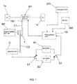
- the vehicle of the invention comprises an electric motor (M1) to drive in rotation the two driving wheels (1 a, 1b) of the vehicle.
- M1 electric motor
- the left-hand driving wheel is indicated with (1 a)
- the right-hand driving wheel is indicated with (1 b).
- the electric motor (M1) comprises a rotor (20a) and a stator (10b).
- the rotor (20a) is splined on a shaft (22a) that is rotatably mounted inside the stator (10b) by means of bearings (5).
- the stator (10b) is rotatably mounted in two fixed supports (4a, 4b) by means of bearings (6). So the stator (10b) can rotate in opposite direction with respect to the rotor (20a).
- the fixed supports (4a, 4b) are joined to the fixed frame of the vehicle.
- the electric motor (M1) can be of direct current type.
- the rotor (20a) of the motor must be powered in current. Therefore, two rows of rotary electric contacts (11 b, 21 a) of brush-type are provided and connected in series.
- the first row of rotary electric contacts (11 b) is disposed outside the stator (10b) inside the fixed support (4b).
- the first row of rotary electric contacts (11 b) provides for a rotary collector integral with an end section of the stator and brushes joined to the fixed support (4b) and electrically connected to an electronic regulation unit (100) of the vehicle used to power the electric motor (M1).
- a suitable control system to modulate the revolution speed of the motor (M1) according to the acceleration given by the user to the vehicle is implemented in the electronic regulation unit (100). In case of direct current motor the control system of the electronic unit (100) regulates the current intensity.
- the second row of rotary electric contacts (21 a) is arranged inside the stator (10b) to provide electric communication between stator and rotor.
- the second row of rotary electric contacts (21 a) provides for a collector joined to the rotor and a set of brushes integral with the stator.
- Fig. 3 shows a preferred embodiment of the alternating current electric motor (M1).
- M1 alternating current electric motor
- a simple regulation unit (100) is no longer sufficient with the alternating current motor, and a transformer (101) is necessary to transform the current of the battery from direct to alternating, perhaps not perfectly sinusoidal (for example halfway between sinusoidal and square wave).
- a suitable control system is implemented in the electronic regulation unit (100), such for example an inverter, which regulates the frequency of the alternating current in such a way to vary the revolution speed of the electric motor (M1).
- the electronic regulation unit (100) such for example an inverter, which regulates the frequency of the alternating current in such a way to vary the revolution speed of the electric motor (M1).
- the alternating current must reach the stator of the motor (and no longer the rotor). In such a case only the first row of rotary contacts is necessary (11 b).
- the alternating current motor has several advantages because it is constructively simpler and less expensive than the direct current motor and only needs one row of rotary contacts.
- the transformer (101) and the inverter of the electronic unit (100) are not a constructive complication and do not involve a significant cost increase with respect to the economic advantages for the adoption of the alternating current motor.
- a shaft (12b) coaxial with the shaft (22a) of the rotor is splined at the right-hand end of the stator (10b).
- the shaft (12b) of the stator passes through the fixed support (4b) to engage in a reduction gear (3b) mounted in a box (40b) integral with the fixed support (4b). From the reduction gear (3b) an axle shaft (13b) protrudes, on which the right-hand wheel (1 b) is mounted.
- the reduction gear (3b) is of known type and not described in detail. In any case, the reduction gear (3b) can be omitted and therefore the shaft (12b) of the stator becomes the axle shaft that is directly connected to the right-hand wheel (1b).
- the left part of the shaft (22a) of the rotor enters in the left-hand fixed support (4a) and is engaged with a rotation reversing device (7) mounted inside the fixed support (4a).
- An output shaft (23a) comes out of the rotation reversing device (7) and rotates in inverse direction with respect to the input shaft (22a) of the rotor.
- the rotation reversing device (7) comprises a first gear (70) splined on the input shaft (22a).
- the first gear (70) engages with a second gear (71) splined on the output shaft (23a).
- the output shaft (23a) of the rotor engages with a reduction gear (3a) mounted in a box (40a) integral with the fixed support (4a). From the reduction gear (3a) an axle shaft (24a) protrudes, on which the right-hand wheel (1a) is mounted.
- the reduction gears (3a) and (3b) are identical.
- the left-hand axle shaft (24a) is coaxial with the right-hand axle shaft (13b).
- rotation reversing device (7) is disposed between the shaft (22a) of the rotor and the axle shaft (24a) of the right-hand wheel, it appears evident that the rotation reversing device (7) can be disposed between the shaft (12b) of the stator and the axle shaft (13b) of the left-hand wheel.
- the travel of the wheels (1 b) and (1 a) is identical and therefore the rotor (20a) makes the same number of revolutions as the stator (10b) and the driving wheels (1 a, 1 b) revolve at the same speed.
- this configuration of electric motor also acts as differential gear, automatically distributing the rotational speed of the wheels (1 a, 1 b) during the curves.
- the motor vehicle of the invention comprises an endothermic motor (M2), an electric generator (G) and two batteries (B1, B2).
- the drive shaft of the endothermic motor (M2) is connected to a clutch (F).
- the clutch (F) is a three-way clutch and allows for coupling the drive shaft of the endothermic motor with the stator (10b) of the electric motor and/or a shaft of the electric generator (G), for example by means of belt or chain drives (C1, C2).
- the electric generator (G) is electrically connected to a first switch (S1) that can switch between the input of a first battery (B1) and the input of a second battery (B2).
- a second switch (S2) electrically connected to the electronic regulation unit (100) that powers the electric motor (M1) can switch between the output of the first battery (B1) and the output of the second battery (B2).
- the switches (S1) and (S2) are mutually switched on the two batteries (B1, B2). This means that if the first switch (S1) is switched on the first battery (B1), the second switch (S2) is normally switched on the second battery (B2). In such a way the first battery (B1) is charged by the generator (G) and the second battery (B2) is used to power the electric motor (M1).
- the endothermic motor (M2) operates at steady state.
- the endothermic motor (M2) is not responsible for regulating the rotational speed of the driving wheels (1 a, 1b), since this function is exclusively carried out by the electric motor (M1).
- the endothermic motor can perform three functions:
- the regulation unit (100) is connected to a potentiometer of the accelerator (200) that sends a current signal proportional to the intensity of the acceleration given by the driver. In this way the electronic unit (100) sends the electric motor (M1) an amount of current proportional to the acceleration given by the driver regulating the rotational speed of the electric motor (M1).
- the regulation unit (100) is also connected to a brake sensor (300) that sends a command signal to the unit (100) when the driver brakes. In this way the electronic unit (100) interrupts the power of the electric motor (M1) and allows for current flow from the electric motor (M1) to the battery (B2). Therefore the electric motor (M1) is converted into generator taking advantage of the inertial motion of rotor and stator. Consequently, the electric motor (M1) produces current to power the battery (B2) connected to it.
Landscapes
- Engineering & Computer Science (AREA)
- Transportation (AREA)
- Mechanical Engineering (AREA)
- Chemical & Material Sciences (AREA)
- Combustion & Propulsion (AREA)
- Power Engineering (AREA)
- Life Sciences & Earth Sciences (AREA)
- Sustainable Development (AREA)
- Sustainable Energy (AREA)
- Electric Propulsion And Braking For Vehicles (AREA)
- Arrangement Or Mounting Of Propulsion Units For Vehicles (AREA)
- Connection Of Motors, Electrical Generators, Mechanical Devices, And The Like (AREA)
- Hybrid Electric Vehicles (AREA)
Claims (8)
- Kraftfahrzeug umfassend:- einen Elektromotor (M1), umfassend einen Rotor (20a), der drehbar in einem Ständer (10b) eingebaut ist, wobei der Elektromotor (M1) geeignet ist, zwei Halbachsen (24a, 13b) in Drehung zu versetzen, auf denen jeweils Antriebsräder (1 a, 1 b) des Kraftfahrzeugs eingebaut sind,- mindestens eine Batterie (B1, B2), die geeignet ist, den Elektromotor (M1) elektrisch zu speisen (M1), und
eine elektronische Steuereinheit (100), die mit einem Potentiometer des Gaspedals (200) verbunden ist, um die Stromversorgung des Elektromotors (M1) zu regeln,
wobei
der Ständer (10b) des Elektromotors drehbar auf zwei fest mit dem Fahrzeuggestell verbundenen Halterungen (4qa, 4b) eingebaut ist, um sich gegen die Drehrichtung des Motors (20b) zu drehen,
wobei eine Halbachse (13b) eines Rades mit dem Ständer (10b) wirkverbunden ist, um von dem Ständer in Drehung versetzt zu werden, wobei die Halbachse (24a) des anderen Rades mit dem Rotor (20a) wirkverbunden ist, um vom Rotor in Drehung versetzt zu werden,
wobei das Fahrzeug außerdem Folgendes umfasst:- eine Drehumkehrvorrichtung (7) zur Umkehrung der Drehung einer (24a oder 13b) der beiden Halbachsen bezogen auf die Drehung des Rotors (20a) oder des Ständers (10b),
dadurch gekennzeichnet, dass das Kraftfahrzeug ferner Folgendes umfasst:- einen endothermischen Motor (M2), der mit einer Antriebswelle versehen ist,- einen Stromerzeuger (G), der mit der mindestens einen Batterie (B1, B2) verbunden ist, und- eine Dreiwegkupplung (F) zur Kupplung der Antriebswelle des endothermischen Motors (M2) mit dem Stromerzeuger (G) und/oder dem Ständer (10b) des Elektromotors (M1). - Kraftfahrzeug nach Anspruch 1, dadurch gekennzeichnet, dass die Drehumkehrvorrichtung (7) ein erstes Zahnrad (70) umfasst, das auf eine mit dem Rotor oder dem Ständer verbundene Welle (22a) aufgezogen ist, das in ein zweites Zahnrad (71) eingreift, das auf eine mit einer Halbachse (24a) verbundene Welle (23a) aufgezogen ist.
- Kraftfahrzeug nach Anspruch 1 oder 2, dadurch gekennzeichnet, dass es zwei Untersetzungsgetriebe (3a, 3b) umfasst, die zwischen dem Rotor (20a) und der Halbachse (24a) eines Rades bzw. zwischen dem Ständer (10b) und der Halbachse (13b) des anderen Rades eingebaut sind.
- Kraftfahrzeug nach einem der vorstehenden Ansprüche, dadurch gekennzeichnet, dass der endothermische Motor (M2) im stationären Zustand betrieben wird.
- Kraftfahrzeug nach einem der vorstehenden Ansprüche, dadurch gekennzeichnet, dass die Kupplung (F) mit dem Ständer (10b) des Elektromotors über ein erstes Riemen- oder Kettenantriebsgetriebe (C1) verbunden ist und die Dreiwegkupplung (F) mit einer Welle des Stromerzeugers (G) über ein zweites Riemen- oder Kettenantriebsgetriebe (C2) verbunden ist.
- Kraftfahrzeug nach einem der vorstehenden Ansprüche, dadurch gekennzeichnet, dass es Folgendes umfasst:- zwei Batterien (B1, B2),- einen ersten Schalter (S1), der mit dem Stromerzeuger (G) verbunden und geeignet ist, zwischen dem Eingang der ersten Batterie (B1) und dem Eingang der zweiten Batterie (2) umzuschalten, und- einen zweiten Schalter (S2), der mit der Steuereinheit (100) verbunden ist, die den Elektromotor speist, und geeignet ist, zwischen dem Ausgang der ersten Batterie (B1) und dem Ausgang der zweiten Batterie (B2) umzuschalten.
- Kraftfahrzeug nach einem der vorstehenden Ansprüche, dadurch gekennzeichnet, dass es einen Bremssensor (300) umfasst, der mit der elektronischen Steuereinheit verbunden ist, um die Stromflussumkehr vom Elektromotor (M1) zur Batterie so zu steuern, dass der Elektromotor beim Bremsvorgang des Kraftfahrzeugs als Stromerzeuger funktioniert.
- Kraftfahrzeug nach einem der vorstehenden Ansprüche, dadurch gekennzeichnet, dass der Elektromotor (M1) vom Typ Wechselstrommotor ist und einen elektrischen Drehkontakt (11 b) umfasst, um den Drehständer (10b) elektrisch mit der elektronischen Steuereinheit (100) zu verbinden, wobei die elektronische Steuereinheit (100) einen Stromwandler (101) umfasst, um den Gleichstrom der Batterie (B1, B2) in Wechselstrom umzuwandeln, und einen Wechselrichter, um die Frequenz des an den Elektromotor gelieferten Wechselstroms zu kontrollieren.
Applications Claiming Priority (2)
| Application Number | Priority Date | Filing Date | Title |
|---|---|---|---|
| ITAN2009A000075A IT1396101B1 (it) | 2009-10-08 | 2009-10-08 | Veicolo automobilistico con motore elettrico |
| PCT/EP2010/064130 WO2011042317A1 (en) | 2009-10-08 | 2010-09-24 | Motor vehicle with electric motor. |
Publications (2)
| Publication Number | Publication Date |
|---|---|
| EP2485909A1 EP2485909A1 (de) | 2012-08-15 |
| EP2485909B1 true EP2485909B1 (de) | 2013-11-06 |
Family
ID=42173939
Family Applications (1)
| Application Number | Title | Priority Date | Filing Date |
|---|---|---|---|
| EP10765985.6A Not-in-force EP2485909B1 (de) | 2009-10-08 | 2010-09-24 | Kraftfahrzeug mit elektrischem antrieb |
Country Status (7)
| Country | Link |
|---|---|
| US (1) | US8844659B2 (de) |
| EP (1) | EP2485909B1 (de) |
| JP (1) | JP2013507286A (de) |
| KR (1) | KR20120084737A (de) |
| ES (1) | ES2445534T3 (de) |
| IT (1) | IT1396101B1 (de) |
| WO (1) | WO2011042317A1 (de) |
Families Citing this family (8)
| Publication number | Priority date | Publication date | Assignee | Title |
|---|---|---|---|---|
| EP2578438B1 (de) | 2012-01-10 | 2017-04-26 | Volvo Car Corporation | Doppelwellenmotor |
| SE536519C2 (sv) * | 2012-06-27 | 2014-01-28 | Scania Cv Ab | Drivsystem och förfarande för att driva ett fordon |
| US20140053541A1 (en) * | 2012-08-24 | 2014-02-27 | Chrysler Group Llc | Vehicle energy storage system and method of use |
| EP3027449A1 (de) * | 2013-08-01 | 2016-06-08 | Casali, Simone | Elektromotoranordnung |
| US9906105B1 (en) | 2014-01-28 | 2018-02-27 | Maestra Energy, Llc | Electrical induction motor with reconfigured rotor mounted commutators for receiving an armature current from a stator mounted brush component along with a reversing gear arrangement for driving a pair of opposite gear rings |
| US9906106B1 (en) | 2014-01-31 | 2018-02-27 | Maestra Energy, Llc | Electrical generator or motor with variable coil winding patterns exhibiting multiple wires incorporated into a plurality coil configurations defined around a rotor and incorporating a gearbox arrangement exhibiting oppositely driven rotor and stator gears configured with multi-tiered reversing gears exhibiting both straight and helical patterns and for varying turning ratios for establishing either of acceleration or deceleration aspects for increased power output |
| US9825514B1 (en) | 2014-02-05 | 2017-11-21 | Maestra Energy, Llc | Electrical generator or motor with variable coil winding patterns exhibiting multiple wires incorporated into a plurality of independent three stage coil configurations and incorporating a belt drive arrangement exhibiting first and second rotating pully wheels in combination with opposite belt rotating magnet and coil supporting components for providing increased power output |
| CN106604841A (zh) * | 2014-08-22 | 2017-04-26 | 博格华纳公司 | 用于通过道路型混合动力车辆的多模式离合器 |
Family Cites Families (14)
| Publication number | Priority date | Publication date | Assignee | Title |
|---|---|---|---|---|
| US3620323A (en) * | 1968-05-31 | 1971-11-16 | Nissan Motor | Electromechanical power train system for an automotive vehicle |
| JP3211626B2 (ja) * | 1994-06-29 | 2001-09-25 | トヨタ自動車株式会社 | ハイブリッド車 |
| US6433451B1 (en) * | 1995-07-16 | 2002-08-13 | Traian Cherciu | Method and electric motor with rotational stator |
| IT1290820B1 (it) * | 1997-03-25 | 1998-12-11 | Nuova Maip Macchine Agric | Veicolo particolarmente carrello elevatore azionato da un motore elettrico con statore e rotore controrotanti |
| JP2001057706A (ja) * | 1999-08-09 | 2001-02-27 | Mazda Motor Corp | 車両の駆動装置 |
| JP2001119813A (ja) * | 1999-10-19 | 2001-04-27 | Shigeo Tanahashi | 電気自動車および充電装置 |
| JP3458818B2 (ja) * | 2000-03-30 | 2003-10-20 | 日産自動車株式会社 | 変速比無限大無段変速機の制御装置 |
| JP2004276833A (ja) * | 2003-03-18 | 2004-10-07 | Toyoda Mach Works Ltd | 車両用操舵装置 |
| CA2430157A1 (fr) * | 2003-05-30 | 2004-11-30 | Tm4 Inc. | Systeme de traction pour vehicule electrique |
| JP4029874B2 (ja) * | 2003-09-29 | 2008-01-09 | 日産自動車株式会社 | 車両の駆動装置 |
| US7270203B2 (en) * | 2004-02-09 | 2007-09-18 | Ut-Battelle, Llc | Electric machine for hybrid motor vehicle |
| US7347803B2 (en) * | 2004-10-27 | 2008-03-25 | Aisin Aw Co., Ltd. | Drive apparatus for hybrid vehicle and control method and control device thereof |
| JP5024618B2 (ja) * | 2007-11-30 | 2012-09-12 | 日立オートモティブシステムズ株式会社 | 電動モータ制御装置及び電動倍力装置 |
| US8272464B2 (en) * | 2008-04-04 | 2012-09-25 | GM Global Technology Operations LLC | Motor assembly for alternative fuel vehicles |
-
2009
- 2009-10-08 IT ITAN2009A000075A patent/IT1396101B1/it active
-
2010
- 2010-09-24 JP JP2012532531A patent/JP2013507286A/ja active Pending
- 2010-09-24 EP EP10765985.6A patent/EP2485909B1/de not_active Not-in-force
- 2010-09-24 ES ES10765985.6T patent/ES2445534T3/es active Active
- 2010-09-24 WO PCT/EP2010/064130 patent/WO2011042317A1/en not_active Ceased
- 2010-09-24 US US13/500,730 patent/US8844659B2/en active Active
- 2010-09-24 KR KR1020127009826A patent/KR20120084737A/ko not_active Withdrawn
Also Published As
| Publication number | Publication date |
|---|---|
| US20120197474A1 (en) | 2012-08-02 |
| WO2011042317A1 (en) | 2011-04-14 |
| US8844659B2 (en) | 2014-09-30 |
| ES2445534T3 (es) | 2014-03-03 |
| JP2013507286A (ja) | 2013-03-04 |
| ITAN20090075A1 (it) | 2011-04-09 |
| EP2485909A1 (de) | 2012-08-15 |
| IT1396101B1 (it) | 2012-11-16 |
| KR20120084737A (ko) | 2012-07-30 |
Similar Documents
| Publication | Publication Date | Title |
|---|---|---|
| EP2485909B1 (de) | Kraftfahrzeug mit elektrischem antrieb | |
| KR101990659B1 (ko) | 순수하게 전기적으로 구동 가능한 자동차의 구동 트레인 | |
| US8960341B2 (en) | Continuously variable electric drive module for electric vehicles | |
| JP6666449B2 (ja) | 動力装置 | |
| EP2451667B1 (de) | Antriebsvorrichtung für ein kraftfahrzeug mit einer elektrische maschinen aufweisenden portalachse | |
| US6328123B1 (en) | Electrical drive for a wheel hub | |
| KR970704590A (ko) | 동력전달장치 및 이것을 사용한 4륜구동차량 및 동력전달방법 및 4륜구동방법(transmission system, four-wheel drive vehicle using the same, power transmitting method, and four-wheel driving method) | |
| JP2005147404A (ja) | ハイブリッド動力伝達機構 | |
| CN106660447B (zh) | 混合驱动系统 | |
| US20240425126A1 (en) | Motor drive assembly for a dual path electric powertrain of a machine | |
| CN109421530A (zh) | 电动(4wd)四轮驱动装置 | |
| CN113173065A (zh) | 双电机驱动系统及电动汽车 | |
| US20060151220A1 (en) | Apparatus capable of running using electric wheels | |
| US7481730B2 (en) | Multiple input, dual output electric differential motor transmission system | |
| CN109314434B (zh) | 包括用于对电池充电的车轮驱动的发电机的车辆 | |
| JP3449284B2 (ja) | 四輪駆動装置 | |
| JP2004322753A (ja) | 車両の左右輪駆動装置 | |
| KR100748759B1 (ko) | 하이브리드 차량용 사륜 구동 장치 | |
| KR20180068248A (ko) | 인휠 모터를 갖는 친환경 차량의 동력전달장치 | |
| CN104691323A (zh) | 电动四轮驱动系统和具有该系统的前轮驱动车辆 | |
| KR20250042502A (ko) | 상용차량용 액슬 장치 | |
| GB2478333A (en) | Two or more motors operable in either series or parallel |
Legal Events
| Date | Code | Title | Description |
|---|---|---|---|
| PUAI | Public reference made under article 153(3) epc to a published international application that has entered the european phase |
Free format text: ORIGINAL CODE: 0009012 |
|
| 17P | Request for examination filed |
Effective date: 20120507 |
|
| AK | Designated contracting states |
Kind code of ref document: A1 Designated state(s): AL AT BE BG CH CY CZ DE DK EE ES FI FR GB GR HR HU IE IS IT LI LT LU LV MC MK MT NL NO PL PT RO SE SI SK SM TR |
|
| DAX | Request for extension of the european patent (deleted) | ||
| GRAP | Despatch of communication of intention to grant a patent |
Free format text: ORIGINAL CODE: EPIDOSNIGR1 |
|
| INTG | Intention to grant announced |
Effective date: 20130513 |
|
| GRAS | Grant fee paid |
Free format text: ORIGINAL CODE: EPIDOSNIGR3 |
|
| GRAA | (expected) grant |
Free format text: ORIGINAL CODE: 0009210 |
|
| AK | Designated contracting states |
Kind code of ref document: B1 Designated state(s): AL AT BE BG CH CY CZ DE DK EE ES FI FR GB GR HR HU IE IS IT LI LT LU LV MC MK MT NL NO PL PT RO SE SI SK SM TR |
|
| REG | Reference to a national code |
Ref country code: GB Ref legal event code: FG4D |
|
| REG | Reference to a national code |
Ref country code: CH Ref legal event code: EP |
|
| REG | Reference to a national code |
Ref country code: AT Ref legal event code: REF Ref document number: 639206 Country of ref document: AT Kind code of ref document: T Effective date: 20131215 |
|
| REG | Reference to a national code |
Ref country code: IE Ref legal event code: FG4D |
|
| REG | Reference to a national code |
Ref country code: DE Ref legal event code: R096 Ref document number: 602010011580 Country of ref document: DE Effective date: 20140102 |
|
| REG | Reference to a national code |
Ref country code: ES Ref legal event code: FG2A Ref document number: 2445534 Country of ref document: ES Kind code of ref document: T3 Effective date: 20140303 |
|
| REG | Reference to a national code |
Ref country code: NL Ref legal event code: VDEP Effective date: 20131106 |
|
| REG | Reference to a national code |
Ref country code: AT Ref legal event code: MK05 Ref document number: 639206 Country of ref document: AT Kind code of ref document: T Effective date: 20131106 |
|
| REG | Reference to a national code |
Ref country code: LT Ref legal event code: MG4D |
|
| PG25 | Lapsed in a contracting state [announced via postgrant information from national office to epo] |
Ref country code: NO Free format text: LAPSE BECAUSE OF FAILURE TO SUBMIT A TRANSLATION OF THE DESCRIPTION OR TO PAY THE FEE WITHIN THE PRESCRIBED TIME-LIMIT Effective date: 20140206 Ref country code: IS Free format text: LAPSE BECAUSE OF FAILURE TO SUBMIT A TRANSLATION OF THE DESCRIPTION OR TO PAY THE FEE WITHIN THE PRESCRIBED TIME-LIMIT Effective date: 20140306 Ref country code: HR Free format text: LAPSE BECAUSE OF FAILURE TO SUBMIT A TRANSLATION OF THE DESCRIPTION OR TO PAY THE FEE WITHIN THE PRESCRIBED TIME-LIMIT Effective date: 20131106 Ref country code: LT Free format text: LAPSE BECAUSE OF FAILURE TO SUBMIT A TRANSLATION OF THE DESCRIPTION OR TO PAY THE FEE WITHIN THE PRESCRIBED TIME-LIMIT Effective date: 20131106 Ref country code: SE Free format text: LAPSE BECAUSE OF FAILURE TO SUBMIT A TRANSLATION OF THE DESCRIPTION OR TO PAY THE FEE WITHIN THE PRESCRIBED TIME-LIMIT Effective date: 20131106 Ref country code: FI Free format text: LAPSE BECAUSE OF FAILURE TO SUBMIT A TRANSLATION OF THE DESCRIPTION OR TO PAY THE FEE WITHIN THE PRESCRIBED TIME-LIMIT Effective date: 20131106 Ref country code: NL Free format text: LAPSE BECAUSE OF FAILURE TO SUBMIT A TRANSLATION OF THE DESCRIPTION OR TO PAY THE FEE WITHIN THE PRESCRIBED TIME-LIMIT Effective date: 20131106 |
|
| PG25 | Lapsed in a contracting state [announced via postgrant information from national office to epo] |
Ref country code: AT Free format text: LAPSE BECAUSE OF FAILURE TO SUBMIT A TRANSLATION OF THE DESCRIPTION OR TO PAY THE FEE WITHIN THE PRESCRIBED TIME-LIMIT Effective date: 20131106 Ref country code: LV Free format text: LAPSE BECAUSE OF FAILURE TO SUBMIT A TRANSLATION OF THE DESCRIPTION OR TO PAY THE FEE WITHIN THE PRESCRIBED TIME-LIMIT Effective date: 20131106 Ref country code: BE Free format text: LAPSE BECAUSE OF FAILURE TO SUBMIT A TRANSLATION OF THE DESCRIPTION OR TO PAY THE FEE WITHIN THE PRESCRIBED TIME-LIMIT Effective date: 20131106 |
|
| PG25 | Lapsed in a contracting state [announced via postgrant information from national office to epo] |
Ref country code: PT Free format text: LAPSE BECAUSE OF FAILURE TO SUBMIT A TRANSLATION OF THE DESCRIPTION OR TO PAY THE FEE WITHIN THE PRESCRIBED TIME-LIMIT Effective date: 20140306 |
|
| PG25 | Lapsed in a contracting state [announced via postgrant information from national office to epo] |
Ref country code: EE Free format text: LAPSE BECAUSE OF FAILURE TO SUBMIT A TRANSLATION OF THE DESCRIPTION OR TO PAY THE FEE WITHIN THE PRESCRIBED TIME-LIMIT Effective date: 20131106 |
|
| REG | Reference to a national code |
Ref country code: DE Ref legal event code: R097 Ref document number: 602010011580 Country of ref document: DE |
|
| PG25 | Lapsed in a contracting state [announced via postgrant information from national office to epo] |
Ref country code: IT Free format text: LAPSE BECAUSE OF FAILURE TO SUBMIT A TRANSLATION OF THE DESCRIPTION OR TO PAY THE FEE WITHIN THE PRESCRIBED TIME-LIMIT Effective date: 20131106 Ref country code: PL Free format text: LAPSE BECAUSE OF FAILURE TO SUBMIT A TRANSLATION OF THE DESCRIPTION OR TO PAY THE FEE WITHIN THE PRESCRIBED TIME-LIMIT Effective date: 20131106 Ref country code: SK Free format text: LAPSE BECAUSE OF FAILURE TO SUBMIT A TRANSLATION OF THE DESCRIPTION OR TO PAY THE FEE WITHIN THE PRESCRIBED TIME-LIMIT Effective date: 20131106 Ref country code: RO Free format text: LAPSE BECAUSE OF FAILURE TO SUBMIT A TRANSLATION OF THE DESCRIPTION OR TO PAY THE FEE WITHIN THE PRESCRIBED TIME-LIMIT Effective date: 20131106 Ref country code: CZ Free format text: LAPSE BECAUSE OF FAILURE TO SUBMIT A TRANSLATION OF THE DESCRIPTION OR TO PAY THE FEE WITHIN THE PRESCRIBED TIME-LIMIT Effective date: 20131106 |
|
| PLBE | No opposition filed within time limit |
Free format text: ORIGINAL CODE: 0009261 |
|
| STAA | Information on the status of an ep patent application or granted ep patent |
Free format text: STATUS: NO OPPOSITION FILED WITHIN TIME LIMIT |
|
| PG25 | Lapsed in a contracting state [announced via postgrant information from national office to epo] |
Ref country code: DK Free format text: LAPSE BECAUSE OF FAILURE TO SUBMIT A TRANSLATION OF THE DESCRIPTION OR TO PAY THE FEE WITHIN THE PRESCRIBED TIME-LIMIT Effective date: 20131106 |
|
| 26N | No opposition filed |
Effective date: 20140807 |
|
| REG | Reference to a national code |
Ref country code: DE Ref legal event code: R097 Ref document number: 602010011580 Country of ref document: DE Effective date: 20140807 |
|
| PGFP | Annual fee paid to national office [announced via postgrant information from national office to epo] |
Ref country code: FR Payment date: 20140930 Year of fee payment: 5 Ref country code: ES Payment date: 20140930 Year of fee payment: 5 Ref country code: DE Payment date: 20140930 Year of fee payment: 5 |
|
| PG25 | Lapsed in a contracting state [announced via postgrant information from national office to epo] |
Ref country code: SI Free format text: LAPSE BECAUSE OF FAILURE TO SUBMIT A TRANSLATION OF THE DESCRIPTION OR TO PAY THE FEE WITHIN THE PRESCRIBED TIME-LIMIT Effective date: 20131106 |
|
| PGFP | Annual fee paid to national office [announced via postgrant information from national office to epo] |
Ref country code: IT Payment date: 20140929 Year of fee payment: 5 |
|
| PGRI | Patent reinstated in contracting state [announced from national office to epo] |
Ref country code: IT Effective date: 20150101 |
|
| PG25 | Lapsed in a contracting state [announced via postgrant information from national office to epo] |
Ref country code: MC Free format text: LAPSE BECAUSE OF FAILURE TO SUBMIT A TRANSLATION OF THE DESCRIPTION OR TO PAY THE FEE WITHIN THE PRESCRIBED TIME-LIMIT Effective date: 20131106 Ref country code: LU Free format text: LAPSE BECAUSE OF FAILURE TO SUBMIT A TRANSLATION OF THE DESCRIPTION OR TO PAY THE FEE WITHIN THE PRESCRIBED TIME-LIMIT Effective date: 20140924 |
|
| REG | Reference to a national code |
Ref country code: CH Ref legal event code: PL |
|
| GBPC | Gb: european patent ceased through non-payment of renewal fee |
Effective date: 20140924 |
|
| REG | Reference to a national code |
Ref country code: IE Ref legal event code: MM4A |
|
| PG25 | Lapsed in a contracting state [announced via postgrant information from national office to epo] |
Ref country code: CH Free format text: LAPSE BECAUSE OF NON-PAYMENT OF DUE FEES Effective date: 20140930 Ref country code: LI Free format text: LAPSE BECAUSE OF NON-PAYMENT OF DUE FEES Effective date: 20140930 Ref country code: GB Free format text: LAPSE BECAUSE OF NON-PAYMENT OF DUE FEES Effective date: 20140924 |
|
| PG25 | Lapsed in a contracting state [announced via postgrant information from national office to epo] |
Ref country code: IE Free format text: LAPSE BECAUSE OF NON-PAYMENT OF DUE FEES Effective date: 20140924 |
|
| REG | Reference to a national code |
Ref country code: DE Ref legal event code: R119 Ref document number: 602010011580 Country of ref document: DE |
|
| PG25 | Lapsed in a contracting state [announced via postgrant information from national office to epo] |
Ref country code: SM Free format text: LAPSE BECAUSE OF FAILURE TO SUBMIT A TRANSLATION OF THE DESCRIPTION OR TO PAY THE FEE WITHIN THE PRESCRIBED TIME-LIMIT Effective date: 20131106 Ref country code: IT Free format text: LAPSE BECAUSE OF FAILURE TO SUBMIT A TRANSLATION OF THE DESCRIPTION OR TO PAY THE FEE WITHIN THE PRESCRIBED TIME-LIMIT Effective date: 20150924 |
|
| PG25 | Lapsed in a contracting state [announced via postgrant information from national office to epo] |
Ref country code: MT Free format text: LAPSE BECAUSE OF FAILURE TO SUBMIT A TRANSLATION OF THE DESCRIPTION OR TO PAY THE FEE WITHIN THE PRESCRIBED TIME-LIMIT Effective date: 20131106 Ref country code: GR Free format text: LAPSE BECAUSE OF FAILURE TO SUBMIT A TRANSLATION OF THE DESCRIPTION OR TO PAY THE FEE WITHIN THE PRESCRIBED TIME-LIMIT Effective date: 20140207 Ref country code: BG Free format text: LAPSE BECAUSE OF FAILURE TO SUBMIT A TRANSLATION OF THE DESCRIPTION OR TO PAY THE FEE WITHIN THE PRESCRIBED TIME-LIMIT Effective date: 20131106 Ref country code: CY Free format text: LAPSE BECAUSE OF FAILURE TO SUBMIT A TRANSLATION OF THE DESCRIPTION OR TO PAY THE FEE WITHIN THE PRESCRIBED TIME-LIMIT Effective date: 20131106 |
|
| REG | Reference to a national code |
Ref country code: FR Ref legal event code: ST Effective date: 20160531 |
|
| PG25 | Lapsed in a contracting state [announced via postgrant information from national office to epo] |
Ref country code: HU Free format text: LAPSE BECAUSE OF FAILURE TO SUBMIT A TRANSLATION OF THE DESCRIPTION OR TO PAY THE FEE WITHIN THE PRESCRIBED TIME-LIMIT; INVALID AB INITIO Effective date: 20100924 Ref country code: TR Free format text: LAPSE BECAUSE OF FAILURE TO SUBMIT A TRANSLATION OF THE DESCRIPTION OR TO PAY THE FEE WITHIN THE PRESCRIBED TIME-LIMIT Effective date: 20131106 Ref country code: DE Free format text: LAPSE BECAUSE OF NON-PAYMENT OF DUE FEES Effective date: 20160401 |
|
| PG25 | Lapsed in a contracting state [announced via postgrant information from national office to epo] |
Ref country code: FR Free format text: LAPSE BECAUSE OF NON-PAYMENT OF DUE FEES Effective date: 20150930 |
|
| REG | Reference to a national code |
Ref country code: ES Ref legal event code: FD2A Effective date: 20161028 |
|
| PG25 | Lapsed in a contracting state [announced via postgrant information from national office to epo] |
Ref country code: ES Free format text: LAPSE BECAUSE OF NON-PAYMENT OF DUE FEES Effective date: 20150925 |
|
| PG25 | Lapsed in a contracting state [announced via postgrant information from national office to epo] |
Ref country code: MK Free format text: LAPSE BECAUSE OF FAILURE TO SUBMIT A TRANSLATION OF THE DESCRIPTION OR TO PAY THE FEE WITHIN THE PRESCRIBED TIME-LIMIT Effective date: 20131106 |
|
| PG25 | Lapsed in a contracting state [announced via postgrant information from national office to epo] |
Ref country code: AL Free format text: LAPSE BECAUSE OF FAILURE TO SUBMIT A TRANSLATION OF THE DESCRIPTION OR TO PAY THE FEE WITHIN THE PRESCRIBED TIME-LIMIT Effective date: 20131106 |
|
| RIC2 | Information provided on ipc code assigned after grant |
Ipc: B60K 6/44 20071001ALI20110426BHEP Ipc: B60K 6/26 20071001ALI20110426BHEP Ipc: B60K 7/00 20060101AFI20110426BHEP Ipc: B60K 6/46 20071001ALI20110426BHEP |