EP2489795A1 - Betätigungsplatte für Spülauslösung - Google Patents
Betätigungsplatte für Spülauslösung Download PDFInfo
- Publication number
- EP2489795A1 EP2489795A1 EP11154625A EP11154625A EP2489795A1 EP 2489795 A1 EP2489795 A1 EP 2489795A1 EP 11154625 A EP11154625 A EP 11154625A EP 11154625 A EP11154625 A EP 11154625A EP 2489795 A1 EP2489795 A1 EP 2489795A1
- Authority
- EP
- European Patent Office
- Prior art keywords
- actuating
- locking element
- locking
- actuating device
- revision
- Prior art date
- Legal status (The legal status is an assumption and is not a legal conclusion. Google has not performed a legal analysis and makes no representation as to the accuracy of the status listed.)
- Granted
Links
Images


Classifications
-
- E—FIXED CONSTRUCTIONS
- E03—WATER SUPPLY; SEWERAGE
- E03D—WATER-CLOSETS OR URINALS WITH FLUSHING DEVICES; FLUSHING VALVES THEREFOR
- E03D5/00—Special constructions of flushing devices, e.g. closed flushing system
- E03D5/02—Special constructions of flushing devices, e.g. closed flushing system operated mechanically or hydraulically (or pneumatically) also details such as push buttons, levers and pull-card therefor
-
- E—FIXED CONSTRUCTIONS
- E03—WATER SUPPLY; SEWERAGE
- E03D—WATER-CLOSETS OR URINALS WITH FLUSHING DEVICES; FLUSHING VALVES THEREFOR
- E03D5/00—Special constructions of flushing devices, e.g. closed flushing system
- E03D5/02—Special constructions of flushing devices, e.g. closed flushing system operated mechanically or hydraulically (or pneumatically) also details such as push buttons, levers and pull-card therefor
- E03D5/028—Pusher plates and actuating mechanisms for built-in cisterns
Definitions
- the present invention relates to an actuating device for a drain valve of a cistern according to the preamble of claim 1.
- the present invention has for its object to provide an actuator, the actuating element (s) are easier to move into a revision position.
- the actuating device further comprises at least one locking element, which provides for the at least one actuating element a stop against movement from the starting position to the revision position, wherein the locking element of the at least one actuating element with respect to the movement in the revision position blocking position in the at least one actuating element with respect to the movement in the revision position releasing position is movable. Consequently, the at least one actuating element can be released via the at least one locking element so that it can be moved from the starting position into the revision position.
- the arrangement of such a locking element a particularly advantageous and easy for the installer to use solution can be provided.
- the at least one actuating element has a stop element, in particular in the form of a locking cam, which is in the initial position with the locking element, which is in the blocking position, in communication or abuts against this or abuts and so movement in the direction of Auditing prevented.
- a stop element in particular in the form of a locking cam, which is in the initial position with the locking element, which is in the blocking position, in communication or abuts against this or abuts and so movement in the direction of Auditing prevented.
- the locking element preferably comprises an actuating portion, by means of which the locking element is movable from the blocking position into the position releasing the actuating element.
- the locking element is movably mounted in a guide track in the actuator plate.
- the guideway is preferably arranged so that it is not visible when mounted actuator plate. The guideway is therefore on the back of the actuator plate.
- the locking element is arranged such that it is accessible from the outside when mounted on a wall actuating device and in particular without the aid of a tool is actuated.
- This allows the installer in case of a revision particularly easy release the actuators.
- the inexperienced installer can already see from the outside, as the actuators are to be released, which prevents him from using a wrong tool and thus damage the device.
- the at least one actuating element is preferably pressed against the locking element by a spring element arranged between the actuating element and the actuating plate, in particular by a leaf spring, and is thus held in the starting position.
- the spring element acts to support when the actuating plates are moved to the revision position.
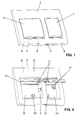
- FIG. 1 an actuator for a drain valve of a cistern is shown.
- the actuating device serves to trigger a flushing process of a cistern, which communicates with, for example, a urinal or a toilet.
- the operating buttons 1, 2 are connected by hinges 11 with the actuator plate 3 and are in the corresponding receiving space 9, 10. Thus, the operation keys 1, 2 perform a pivoting movement about the hinge 11 from. For each actuating button 1, 2 two hinges 11 are provided. In the region of the receiving spaces 9, 10 apertures 12 are arranged, through which the presser bar can be passed.
- the actuating device further comprises a locking element 4, which provides for the at least one actuating element 1, 2 a stop against movement from the starting position to the revision position. Accordingly, the locking element 4 prevents the actuating element 1, 2 from being movable from the starting position into the revision position without the locking element 4 correspondingly is pressed.
- the locking element 4 is movable from a blocking position to a releasing position. In the blocking position, the locking element 4 is positioned such that abuts the at least one actuating element 1, 2 with respect to the movement in the revision position on the locking element 4, in which case no movement in revision position is executable.
- the locking element 4 In the releasing position, the locking element 4 with respect to the at least one actuating element 1, 2 so that a movement from the starting position is made possible in the revision position.
- the actuator is shown from the rear, in which case the rear side 7 of the wall 5 can be well recognized.
- the locking element 4 is mounted in a guide track 13.
- the guideway 13 is provided here by the side walls of the receiving space 9, 10.
- the locking element 4 is movably mounted and can be moved from the blocking position to the releasing position.
- the locking element 4 is in the blocking position.
- the locking element 4 essentially comprises an actuating portion 14, a bearing portion 15, a stopper portion 16 and a return portion 17.
- the storage section 15 here has two support webs 18, which are formed sprung.
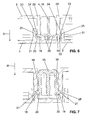
- FIG. 7 a sectional view through the storage section 15 is shown through.
- the guide track 13 has recesses 19 extending parallel thereto into which the bearing webs 18 engage with their end region 20. Due to the resilient design of the bearing webs 18 and the chamfer 21 in the end region 20, the locking element can be in a direction R, which is perpendicular to the operating direction of the locking element 4, insert into the guideway 13.
- the bearing webs 18 are pressed against each other and finally snap into the recesses 19 a.
- the stopper portion 16 which in the FIGS. 4 and 5 is well shown, provides the stop for the actuator plates 1, 2 ready.
- the abutment portion 16 has at least one locking tab 22, here two locking tabs 22, which project laterally from the locking element 4.
- the locking tabs 22 are in contact with a stop element, here a locking cam 23 which is formed on the actuating element 1, 2.
- the locking tab 22 projects through an opening 29 in the actuator plate 3 in the receiving space 9, 10 into it.
- the locking cam 23 is moved away at a Spülauslect of the locking tab 22 towards the end position and occurs in the return movement after flushing again with the locking tab 22 into contact, which then provides a stop against a possible movement in the direction of the revision position.
- the locking cam 23 is in contact with the locking tab 22 so that said movement is prevented.
- FIG. 6 is a sectional view through the locking portion 16, in particular by the locking tabs 22 and the locking cam 23, shown.
- the actuating element 1, 2 are here in the starting position and thus the locking cam 23 is at the respective locking tab 22 at.
- the locking cam 23 includes a tapered surface 24. If now the installer after the revision, the actuators 1, 2 would like to move from the revision position to the starting position, the locking tab 22 is elastically slightly deformed in the sense of a snap connection, so that they skip the locking cam 23 can.
- the locking tab 22 is therefore advantageously formed slightly resilient.
- the locking tab 22 may be connected to a spring portion 26, which slightly tapers the cross section of the locking tab 22 with the locking element 4.
- the locking cam 23 has a stop surface 25, which preferably extends perpendicular or at a small angle to the movement in the direction of the revision position S.
- the locking tabs 22 with respect to the direction of movement of the locking element 4 can be arranged offset from each other. An arrangement at the same height would also be conceivable.
- the locking cam 23 is here formed on the respective actuating button 1, 2 via a connecting portion 31.
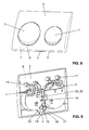
- FIGS. 8 and 9 a second embodiment of an actuator according to the present invention is shown.
- the same parts are provided with the same reference numerals and the operation is in principle identical to that of FIGS. 1 to 7 ,
- buttons 1, 2 are shown, the second embodiment has round or polygonal actuating keys 1, 3.
- the locking element 4 in particular the return portion 17 is formed differently than in the first embodiment.
- the return portion 17 comprises two integrally formed return arms 32 which abut against a corresponding wall 26.
Landscapes
- Engineering & Computer Science (AREA)
- Mechanical Engineering (AREA)
- Aviation & Aerospace Engineering (AREA)
- Health & Medical Sciences (AREA)
- Life Sciences & Earth Sciences (AREA)
- Hydrology & Water Resources (AREA)
- Public Health (AREA)
- Water Supply & Treatment (AREA)
- Preventing Unauthorised Actuation Of Valves (AREA)
Abstract
Description
- Die vorliegende Erfindung betrifft eine Betätigungsvorrichtung für ein Ablaufventil eines Spülkastens gemäss dem Oberbegriff von Anspruch 1.
- Betätigungsplatten mit Betätigungstasten für die Auslösung einer Spülung bei einem Spülkasten sind aus dem Stand der Technik bekannt. Vielfach wird über ein Entfernen der Betätigungstasten, wie beispielsweise durch ein Hochklappen derselben, Zugang zum hinter der Betätigungsplatte angeordneten Spülkasten geschaffen. Somit erhält der Installateur Zugang zum Spülkasten für Revisionszwecke.
- An die Betätigungstasten werden diesbezüglich erhöhte Anforderungen gestellt, weil diese nicht nur bei der Auslösung eines Spülvorgangs von einer Ausgangslage in eine Endlage entlang einer Betätigungsrichtung bewegbar sein sollen, sondern auch entgegen der Betätigungsrichtung in eine Revisionsstellung.
- Ein Problem, welches sich bei den aus dem Stand der Technik bekannten Betätigungsplatten ergibt, ist die Freigabe der Betätigungsplatten zur Bewegung derselben in die Revisionsstellung.
- Ausgehend vom diesem Stand der Technik liegt der vorliegenden Erfindung eine Aufgabe zugrunde, eine Betätigungsvorrichtung anzugeben, deren Betätigungselement(e) einfacher in eine Revisionsstellung bewegbar sind.
- Diese Aufgabe wird durch eine Betätigungsvorrichtung nach Anspruch 1 gelöst. Demgemäss umfasst eine Betätigungsvorrichtung für ein Ablaufventil eines Spülkastens eine Betätigungsplatte, in welcher mindestens ein Betätigungselement für eine Spülauslösung gelagert ist, wobei das mindestens eine Betätigungselement bei der Spülauslösung entlang einer Betätigungsrichtung von einer Ausgangsstellung in eine Endstellung bewegbar ist und wobei das mindestens eine Betätigungselement entlang einer Bewegung gegen die Betätigungsrichtung von der Ausgangsstellung in eine Revisionsstellung bewegbar ist. Die Betätigungsvorrichtung umfasst weiter mindestens ein Verriegelungselement, welches für das mindestens eine Betätigungselement einen Anschlag gegen eine Bewegung von der Ausgangsstellung in die Revisionsstellung bereitstellt, wobei das Verriegelungselement von einer das mindestens eine Betätigungselement bezüglich der Bewegung in die Revisionsstellung blockierenden Position in eine das mindestens eine Betätigungselement bezüglich der Bewegung in die Revisionsstellung freigebende Position bewegbar ist. Folglich kann über das mindestens eine Verriegelungselement das mindestens eine Betätigungselement so freigegeben werden, dass dieses von der Ausgangsstellung in die Revisionsstellung bewegbar ist. Durch die Anordnung eines solchen Verriegelungselementes kann eine besonders vorteilhafte und für den Installateur einfach zu bedienende Lösung bereitgestellt werden.
- Vorzugsweise verfügt das mindestens eine Betätigungselement über ein Anschlagselement, insbesondere in der Gestalt einer Verriegelungsnocke, welches in der Ausgangsstellung mit dem Verriegelungselement, das sich in der blockierenden Stellung befindet, in Verbindung steht bzw. an diesem anliegt oder anschlägt und so eine Bewegung in Richtung der Revisionsstellung verhindert.
- Das Verriegelungselement umfasst vorzugsweise einen Betätigungsabschnitt, über welchen das Verriegelungselement von der blockierenden Position in die das Betätigungselement freigebende Position bewegbar ist.
- Vorzugsweise stellt der Betätigungsabschnitt in der blockierenden Position einen Teil der Wandung der Betätigungsplatte bereit. Diese Anordnung ist besonders vorteilhaft, weil der Installateur bei montierter Betätigungsvorrichtung von ausserhalb der Betätigungsvorrichtung das Verriegelungselement gut erkennen kann.
- Bevorzugt wird das Verriegelungselement in einer Führungsbahn in der Betätigungsplatte bewegbar gelagert. Die Führungsbahn ist vorzugsweise so angeordnet, dass diese bei montierter Betätigungsplatte nicht sichtbar ist. Die Führungsbahn liegt demnach auf der Hinterseite der Betätigungsplatte.
- Vorzugsweise ist das Verriegelungselement derart angeordnet, dass es bei an einer Wand montierter Betätigungsvorrichtung von aussen zugänglich ist und insbesondere ohne die Hilfe eines Werkzeuges betätigbar ist. Dadurch kann der Installateur im Falle einer Revision besonders einfach die Betätigungselemente freigeben. Zudem kann der unerfahrene Installateur bereits von aussen erkennen, wie die Betätigungselemente freizugeben sind, was verhindert, dass er fälschlicherweise ein Werkzeug einsetzt und somit die Vorrichtung beschädigt.
- Bevorzugterweise verfügt das Verriegelungselement über ein Rückstellelement, mit welchem das Verriegelungselement nach erfolgter Betätigung von der freigebenden Position in die blockierende Position bewegbar ist.
- Vorzugsweise ist das Verriegelungselement zwischen zwei Betätigungselementen angeordnet und diese Betätigungselemente stehen mit dem jeweiligen Anschlagselement mit einem gemeinsamen Verriegelungselement in Verbindung. Dadurch können bei einer einzigen Betätigung des Verriegelungselementes zwei Betätigungselemente freigegeben werden.
- Vorzugsweise wird das mindestens eine Betätigungselement durch ein zwischen dem Betätigungselement und der Betätigungsplatte angeordnetes Federelement, insbesondere durch eine Blattfeder, gegen das Verriegelungselement gedrückt und wird so in der Ausgangsstellung gehalten. Zudem wirkt das Federelement unterstützend, wenn die Betätigungsplatten in die Revisionsstellung bewegt werden.
- Weitere Ausführungsformen sind in den abhängigen Ansprüchen angegeben.
- Bevorzugte Ausführungsformen der Erfindung werden im Folgenden anhand der Zeichnungen beschrieben, die lediglich zur Erläuterung dienen und nicht einschränkend auszulegen sind. In den Zeichnungen zeigen:
- Fig. 1
- eine perspektivische Ansicht einer ersten Ausführungsform einer Betätigungsvorrichtung für ein Ablaufventil eines Spülkastens mit Betätigungselementen in der Ausgangsstellung;
- Fig. 2
- die Betätigungsvorrichtung nach
Figur 1 mit den Betätigungselementen in der Revisionsstellung; - Fig. 3
- eine Ansicht der Betätigungsvorrichtung nach
Figuren 1 und 2 von hinten; - Fig. 4
- eine perspektivische Ansicht der Betätigungsvorrichtung nach
Figuren 1 und 2 von hinten; - Fig. 5
- eine Detailansicht nach
Figur 4 ; - Fig. 6
- eine Schnittansicht durch ein Verriegelungselement der Betätigungsvorrichtung nach den vorhergehenden Figuren;
- Fig. 7
- eine Schnittansicht durch die Führung eines Verriegelungselementes der Betätigungsvorrichtung nach den vorhergehenden Figuren;
- Fig. 8
- eine perspektivische Ansicht einer zweiten Ausführungsform Betätigungsvorrichtung für ein Ablaufventil eines Spülkastens mit Betätigungselementen in der Ausgangsstellung; und
- Fig. 9
- eine Ansicht von hinten der
Figur 8 . - In der
Figur 1 wird eine Betätigungsvorrichtung für ein Ablaufventil eines Spülkastens gezeigt. Die Betätigungsvorrichtung dient zur Auslösung eines Spülvorganges eines Spülkastens, welcher beispielsweise mit einem Urinal oder mit einer Toilette in Verbindung steht. - Die Betätigungsvorrichtung umfasst mindestens ein Betätigungselement, hier eine kleine Betätigungstaste 1 und eine grosse Betätigungstaste 2, und eine Betätigungsplatte 3, in welcher die Betätigungstasten 1, 2 gelagert sind. Bei Betätigung des mindestens einen Betätigungselementes 1, 2 wird eine Bewegung bereitgestellt, welche auf eine Drückerstange des Spülkastens übertragen wird. Über diese Drückerstange wird dann das Ablaufventil angehoben und der Spülvorgang wird ausgelöst.
- Die Betätigungstasten 1, 2 sind bei der Spülauslösung entlang einer Betätigungsrichtung von einer Ausgangsstellung in eine Endstellung bewegbar. In der
Fig. 1 sind die Betätigungselemente 1, 2 in der Ausgangstellung gezeigt und bei Spülauslösung werden die Betätigungselemente 1, 2 im Wesentlichen senkrecht zur Zeichnungsfläche zur Betätigungsplatte 3 hin bewegt. - In der
Figur 2 sind die beiden Betätigungselemente 1, 2 in der Revisionsstellung gezeigt, wobei dann das mindestens eine Betätigungselement 1, 2 entlang einer Bewegung gegen die Betätigungsrichtung von der Ausgangsstellung in die Revisionsstellung bewegt wird. - Die Betätigungsplatte 3 umfasst eine Wandung 5, mit einer Vorderseite 6 und einer Hinterseite 7. Über die Hinterseite 7 liegt die Betätigungsplatte 3 an einer Wand vor dem Spülkasten an. Von der Hinterseite 7 gesehen, stellt die Wandung 5 einen Innenraum 8 bereit. Von der Vorderseite 6 gesehen definiert die Wandung 5 mindestens einen Aufnahmeraum, hier zwei Aufnahmeräume 9 und 10, für die Aufnahme der Betätigungselemente 1, 2.
- Die Betätigungstasten 1, 2 sind über Scharniere 11 mit der Betätigungsplatte 3 verbunden und liegen im entsprechenden Aufnahmeraum 9, 10. Somit führen die Betätigungstasten 1, 2 eine Verschwenkbewegung um das Scharnier 11 aus. Pro Betätigungstaste 1, 2 sind jeweils zwei Scharniere 11 vorgesehen. Im Bereich der Aufnahmeräume 9, 10 sind Durchbrüche 12 angeordnet, durch welche die Drückerstange hindurchführbar ist.
- Die Betätigungsvorrichtung umfasst weiter ein Verriegelungselement 4, welches für das mindestens eine Betätigungselement 1, 2 einen Anschlag gegen eine Bewegung von der Ausgangsstellung in die Revisionsstellung bereitstellt. Das Verriegelungselement 4 verhindert demnach, dass das Betätigungselement 1, 2 von der Ausgangsstellung in die Revisionsstellung bewegbar ist, ohne dass das Verriegelungselement 4 entsprechend betätigt wird. Für das Bewegen der Betätigungselemente 1, 2 in die Revisionsstellung ist das Verriegelungselement 4 von einer blockierenden Position in eine freigebende Position bewegbar. In der blockierenden Position ist das Verriegelungselement 4 derart positioniert, dass das mindestens eine Betätigungselement 1, 2 bezüglich der Bewegung in die Revisionsstellung am Verriegelungselement 4 anschlägt, wobei dann keine Bewegung in Revisionsstellung ausführbar ist. In der freigebenden Stellung steht das Verriegelungselement 4 bezüglich dem mindestens einen Betätigungselement 1, 2 so, dass eine Bewegung von der Ausgangsstellung in die Revisionsstellung ermöglicht wird.
- In der
Figur 1 befindet sich das Verriegelungselement 4 in der blockierenden Position, wobei es dabei eben bzw. bündig mit der Vorderseite 6 der Wandung 5 der Betätigungsplatte 3 ist. Mit anderen Worten kann gesagt werden, dass in dieser Stellung das Verriegelungselement 4 einen Teil der Wandung 5 darstellt. In derFigur 2 wird das Verriegelungselement 4 in der freigebenden Position gezeigt, wobei das Verriegelungselement 4 in den Innenraum 8 der Betätigungsplatte 3 geschoben wird, wobei dann die Betätigungselemente bzw. Betätigungstasten 1, 2 in die Revisionsstellung bewegbar sind. - In der
Figur 3 wird die Betätigungsvorrichtung von hinten gezeigt, wobei hier die Hinterseite 7 der Wandung 5 gut erkannt werden kann. Hier kann auch gut erkannt werden, dass das Verriegelungselement 4 in einer Führungsbahn 13 gelagert ist. Die Führungsbahn 13 wird hier durch die Seitenwände des Aufnahmeraums 9, 10 bereitgestellt. In der Führungsbahn 13 ist das Verriegelungselement 4 bewegbar gelagert und kann von der blockierenden Position in die freigebende Position bewegt werden. In derFigur 3 befindet sich das Verriegelungselement 4 in der blockierenden Position. - In der
Figur 4 wird eine perspektivische Ansicht der Betätigungsvorrichtung gezeigt, wobei das Verriegelungselement 4 ausserhalb der Führungsbahn 13 gezeigt wird. In derFigur 5 wird eine Detailansicht derFigur 4 gezeigt. - Das Verriegelungselement 4 umfasst im wesentlichen einen Betätigungsabschnitt 14, einen Lagerungsabschnitt 15, einen Anschlagsabschnitt 16 und einen Rückstellabschnitt 17.
- Über den Betätigungsabschnitt 14 kann der Benutzer bzw. der Installateur das Verriegelungselement 4 von der blockierenden Position in die freigebende Position bewegen. Der Betätigungsabschnitt 14 stellt dabei auch den Bereich bereit, welcher eben bzw. bündig mit der Wandung 5 ist. Der Betätigungsabschnitt 14 ist von ausserhalb der Betätigungsplatte 3 zugänglich.
- Der Lagerungsabschnitt 15 weist hier zwei Lagerungsstege 18 auf, welche gefedert ausgebildet sind. In der
Figur 7 wird eine Schnittdarstellung durch den Lagerungsabschnitt 15 hindurch gezeigt. Die Führungsbahn 13 weist parallel dazu verlaufende Ausnehmungen 19 auf, in welche die Lagerungsstege 18 mit ihrem Endbereich 20 eingreifen. Aufgrund der federnden Ausbildung der Lagerungsstege 18 und der Anschrägung 21 im Endbereich 20 lässt sich das Verriegelungselement in einer Richtung R, welche senkrecht zur Betätigungsrichtung des Verriegelungselementes 4 verläuft, in die Führungsbahn 13 einschieben. Dabei werden die Lagerungsstege 18 gegeneinander gedrückt und rasten schliesslich in den Ausnehmungen 19 ein. - Der Anschlagsabschnitt 16, welcher in den
Figuren 4 und 5 gut gezeigt wird, stellt den Anschlag für die Betätigungsplatten 1, 2 bereit. Der Anschlagsabschnitt 16 verfügt über mindestens eine Verriegelungslasche 22, hier zwei Verriegelungslaschen 22, welche seitlich vom Verriegelungselement 4 abstehen. Die Verriegelungslaschen 22 stehen in Kontakt mit einem Anschlagselement, hier einer Verriegelungsnocke 23, welche am Betätigungselement 1, 2 angeformt ist. Hierfür ragt die Verriegelungslasche 22 durch eine Öffnung 29 in der Betätigungsplatte 3 in den Aufnahmeraum 9, 10 hinein. Die Verriegelungsnocke 23 wird bei einer Spülauslösung von der Verriegelungslasche 22 in Richtung Endstellung wegbewegt und tritt bei der Rückstellbewegung nach dem Spülvorgang wieder mit der Verriegelungslasche 22 in Kontakt, welche dann einen Anschlag entgegen eine mögliche Bewegung in Richtung der Revisionsstellung bereitstellt. Wenn sich das Verriegelungselement 4 in der die Betätigungselemente 1, 2 bezüglich einer Bewegung in die Revision in der blockierenden Stellung befindet, so steht die Verriegelungsnocke 23 mit der der Verriegelungslasche 22 in Kontakt, so dass die besagte Bewegung verhindert wird. - Wenn nun das Verriegelungselement 4 von der blockierenden Stellung in die freigebende Stellung verschoben wird, so verschiebt sich die Verrieglungslasche 22 bezüglich der Verriegelungsnocke 23 derart, dass der Kontakt zwischen Verriegelungslasche 22 und Verriegelungsnocke 23 aufgehoben wird. Folglich kann die Verriegelungsnocke 23 die Verriegelungslasche 22 passieren und das Betätigungselement 1, 2 kann in die Revisionsstellung bewegt werden. Diese Bewegung kann durch ein in den Figuren nicht gezeigtes Federmittel unterstützt werden, wobei das Federmittel bezüglich des Spülvorganges als Rückstellfeder dient, welches die Betätigungselemente 1, 2 von der Endstellung in die Ausgangsstellung bewegen.
- In der
Figur 6 wird eine Schnittdarstellung durch den Verriegelungsabschnitt 16, insbesondere durch die Verriegelungslaschen 22 und die Verriegelungsnocken 23, gezeigt. Die Betätigungselement 1, 2 befinden sich hier in der Ausgangsstellung und somit steht die Verriegelungsnocke 23 an der jeweiligen Verriegelungslasche 22 an. Die Verriegelungsnocke 23 umfasst eine angeschrägte Fläche 24. Wenn nun der Installateur nach erfolgter Revision die Betätigungselemente 1, 2 von der Revisionsstellung in die Ausgangsstellung bewegen möchte, so wird im Sinne einer Schnappverbindung die Verriegelungslasche 22 elastisch leicht verformt, so dass diese die Verriegelungsnocke 23 überspringen kann. Die Verriegelungslasche 22 ist demnach vorteilhafterweise leicht federnd ausgebildet. Um die elastische Verformung zu Gewährleisten kann die Verrieglungslasche 22 mit einem Federabschnitt 26, welcher den Querschnitt der Verriegelungslasche 22 leicht verjüngt mit den Verriegelungselement 4 in Verbindung stehen. - Gegenüber der angeschrägten Fläche 24 weist die Verriegelungsnocke 23 eine Anschlagsfläche 25 auf, welche vorzugsweise senkrecht oder mit einem kleinen Winkel zur Bewegung in Richtung der Revisionsstellung S verläuft.
- Wie in der
Figur 3 erkannt werden kann, können die Verriegelungslaschen 22 bezüglich der Bewegungsrichtung des Verriegelungselementes 4 versetzt voneinander angeordnet sein. Eine Anordnung auf gleicher Höhe wäre auch denkbar. - Die Verriegelungsnocke 23 ist hier an der jeweiligen Betätigungstaste 1, 2 über ein Verbindungsabschnitt 31 angeformt.
- Der Rückstellabschnitt 17 umfasst im wesentlichen ein Federelement 27, welches an einer Wandung 26 der Betätigungsplatte 3 ansteht. Das Federelement 27 stellt eine Kraft in Richtung der Führungsbahn 13 bereit und stellt sicher, dass sich das Verriegelungselement 4 ohne Betätigungskraft in der blockierenden Stellung befindet. In der blockierenden Stellung steht der Lagerungssteg 18 in der Ausnehmung 19 an einer hinteren Anschlagsfläche 28 an, wobei so die Lage des Verriegelungselementes 4 in der Führungsbahn 13 definiert wird.
- Die Betätigungsvorrichtung kann über Befestigungsöffnungen 30, welche in der
Figur 3 gut erkennbar sind, mit einem Spülkasten oder einer Gebäudewand verbunden werden. - In den
Figuren 8 und 9 wird eine zweite Ausführungsform einer Betätigungsvorrichtung gemäss der vorliegenden Erfindung gezeigt. Gleiche Teile sind mit gleichen Bezugszeichen versehen und die Funktionsweise ist prinzipiell identisch zur derjenigen derFiguren 1 bis 7 . - Unterschiedlich ist hier die Gestalt der Betätigungstasten 1, 2. Während in den
Figuren 1 bis 7 rechteckige oder quadratische Betätigungstasten 1, 3 gezeigt werden, weist die zweite Ausführungsform runde bzw. polygonalförmige Betätigungstasten 1, 3 auf. - Von der
Figur 9 kann zudem erkannt werden, dass das Verriegelungselement 4, insbesondere der Rückstellabschnitt 17 anders als bei der ersten Ausführungsform ausgebildet ist. Hier umfasst der Rückstellabschnitt 17 zwei angeformte Rückstellarme 32, welche an einer entsprechenden Wandung 26 anstehen. -
- 1
- Betätigungselement, kleine Betätigungstaste
- 2
- Betätigungselement, grosse Betätigungstaste
- 3
- Betätigungsplatte
- 4
- Verriegelungselement
- 5
- Wandung
- 6
- Vorderseite
- 7
- Hinterseite
- 8
- Innenraum
- 9
- Aufnahmeraum
- 10
- Aufnahmeraum
- 11
- Scharnier
- 12
- Durchbruch
- 13
- Führungsbahn
- 14
- Betätigungsabschnitt
- 15
- Lagerungsabschnitt
- 16
- Verriegelungsabschnitt
- 17
- Rückstellabschnitt
- 18
- Lagerungssteg
- 19
- Ausnehmung
- 20
- Endbereich
- 21
- Anschrägung
- 22
- Verriegelungslasche
- 23
- Verriegelungsnocke
- 24
- angeschrägte Fläche
- 25
- Anschlagsfläche
- 26
- Wandung
- 27
- Federelement
- 28
- Anschlagsfläche
- 29
- Öffnung
- 30
- Befestigungsöffnungen
- 31
- Verbindungsabschnitt
- 32
- Rückstellarm
Claims (11)
- Betätigungsvorrichtung für ein Ablaufventil eines Spülkastens umfassend eine Betätigungsplatte (3), in welcher mindestens ein Betätigungselement (1, 2) für eine Spülauslösung gelagert ist, wobei das mindestens eine Betätigungselement (1, 2) bei der Spülauslösung entlang einer Betätigungsrichtung von einer Ausgangsstellung in eine Endstellung bewegbar ist und wobei das mindestens eine Betätigungselement (1, 2) entlang einer Bewegung gegen die Betätigungsrichtung von der Ausgangsstellung in eine Revisionsstellung bewegbar ist, dadurch gekennzeichnet, dass die Betätigungsvorrichtung weiter mindestens ein Verriegelungselement (4) umfasst, welches für das mindestens eine Betätigungselement (1, 2) einen Anschlag gegen eine Bewegung von der Ausgangsstellung in die Revisionsstellung bereitstellt, wobei das Verriegelungselement (4) von einer das mindestens eine Betätigungselement (1, 2) bezüglich der Bewegung in die Revisionsstellung blockierenden Position in eine das mindestens eine Betätigungselement (1, 2) bezüglich der Bewegung in die Revisionsstellung freigebende Position bewegbar ist.
- Betätigungsvorrichtung nach Anspruch 1, dadurch gekennzeichnet, dass das mindestens eine Betätigungselement (1, 2) über ein Anschlagselement (31, 23) verfügt, welches in der Ausgangsstellung mit dem Verriegelungselement (4) in Verbindung steht und so eine Bewegung in Richtung der Revisionsstellung verhindert.
- Betätigungsvorrichtung nach einem der vorhergehenden Ansprüche, dadurch gekennzeichnet, dass das Verriegelungselement (4) einen Betätigungsabschnitt (14) umfasst, über welchen das Verriegelungselement (4) von der blockierenden in die das Betätigungselement (1, 2) freigebenden Position bewegbar ist.
- Betätigungsvorrichtung nach Anspruch 3, dadurch gekennzeichnet, dass der Betätigungsabschnitt (14) in der blockierenden Position einen Teil der Wandung der Betätigungsplatte (5) bereitstellt.
- Betätigungsvorrichtung nach einem der vorhergehenden Ansprüche, dadurch gekennzeichnet, dass das Verriegelungselement (4) in einer Führungsbahn (13) in der Betätigungsplatte (3) bewegbar gelagert wird.
- Betätigungsvorrichtung nach einem der vorhergehenden Ansprüche, dadurch gekennzeichnet, dass das Verriegelungselement (4) derart angeordnet, dass es bei an einer Wand montierter Betätigungsvorrichtung von aussen zugänglich ist und insbesondere ohne die Hilfe eines Werkzeuges betätigbar ist.
- Betätigungsvorrichtung nach einem der vorhergehenden Ansprüche, dadurch gekennzeichnet, dass das Verriegelungselement (4) über ein Rückstellelement (17, 26) verfügt, mit welchem das Verriegelungselement (4) nach erfolgter Betätigung von der freigebenden Position in die blockierende Position bewegbar ist.
- Betätigungsvorrichtung nach einem der vorhergehenden Ansprüche, dadurch gekennzeichnet, dass das Verriegelungselement (4) zwischen zwei Betätigungselementen (1, 2) angeordnet ist, und dass diese Betätigungselemente (1, 2) mit dem jeweiligen Anschlagselement (23, 31) mit einem gemeinsamen Verriegelungselement (4) in Verbindung steht.
- Betätigungsvorrichtung nach einem der vorhergehenden Ansprüche, dadurch gekennzeichnet, dass das Verriegelungselement (4) eine Verriegelungslasche (22) umfasst, welche mit den Anschlagselement (23, 31) in Verbindung steht, wobei Anschlagselement (23, 31) und Verriegelungslasche (22) derart ausgebildet sind, dass das Anschlagselement (23, 31) bei einer Bewegung von der Revisionsstellung in die Ausgangsstellung über eine elastische Verformung des Anschlagselements (23, 31) und/oder der Verriegelungslasche (22) in die Ausgangsstellung zu liegen kommt.
- Betätigungsvorrichtung nach einem der vorhergehenden Ansprüche, dadurch gekennzeichnet, dass das mindestens eine Betätigungselement (1, 2) durch ein zwischen dem Betätigungselement (1, 2) und der Betätigungsplatte (3) angeordnetes Federelement, insbesondere durch eine Blattfeder, gegen das Verriegelungselement (4) gedrückt wird.
- Betätigungsvorrichtung nach einem der vorhergehenden Ansprüche, dadurch gekennzeichnet, dass das Rückstellelement (17, 26) das Verriegelungselement (4) in der blockierenden Stellung an einen Anschlag, insbesondere an eine Anschlagsfläche (28) drückt.
Priority Applications (2)
| Application Number | Priority Date | Filing Date | Title |
|---|---|---|---|
| EP11154625.5A EP2489795B1 (de) | 2011-02-16 | 2011-02-16 | Betätigungsplatte für Spülauslösung |
| PL11154625T PL2489795T3 (pl) | 2011-02-16 | 2011-02-16 | Urządzenie uruchamiające zawór wylotowy spłuczki |
Applications Claiming Priority (1)
| Application Number | Priority Date | Filing Date | Title |
|---|---|---|---|
| EP11154625.5A EP2489795B1 (de) | 2011-02-16 | 2011-02-16 | Betätigungsplatte für Spülauslösung |
Publications (2)
| Publication Number | Publication Date |
|---|---|
| EP2489795A1 true EP2489795A1 (de) | 2012-08-22 |
| EP2489795B1 EP2489795B1 (de) | 2015-03-25 |
Family
ID=44202135
Family Applications (1)
| Application Number | Title | Priority Date | Filing Date |
|---|---|---|---|
| EP11154625.5A Active EP2489795B1 (de) | 2011-02-16 | 2011-02-16 | Betätigungsplatte für Spülauslösung |
Country Status (2)
| Country | Link |
|---|---|
| EP (1) | EP2489795B1 (de) |
| PL (1) | PL2489795T3 (de) |
Cited By (1)
| Publication number | Priority date | Publication date | Assignee | Title |
|---|---|---|---|---|
| EP3098357A1 (de) | 2015-05-28 | 2016-11-30 | Geberit International AG | Betätigungsvorrichtung für ein ablaufventil eines spülkastens |
Citations (4)
| Publication number | Priority date | Publication date | Assignee | Title |
|---|---|---|---|---|
| DE3139834A1 (de) * | 1980-12-15 | 1982-08-12 | Geberit AG, 8645 Jona, St.Gallen | Betaetigungsvorrichtung fuer das ablaufventil eines unterputz-spuelkastens |
| EP0779397A1 (de) * | 1995-12-16 | 1997-06-18 | Friatec Aktiengesellschaft Keramik- und Kunststoffwerke | Abdeckanordnung |
| EP1889978A2 (de) * | 2006-08-17 | 2008-02-20 | Viega GmbH & Co. KG | Betätigungsvorrichtung für einen Urinal-Unterputzspüler oder WC-Unterputzspülkasten |
| EP2226437A1 (de) * | 2009-03-06 | 2010-09-08 | Geberit International AG | Spülkasten und Verfahren zum zuführen eines Zusatzmittels bei einem solchen Spülkasten |
-
2011
- 2011-02-16 PL PL11154625T patent/PL2489795T3/pl unknown
- 2011-02-16 EP EP11154625.5A patent/EP2489795B1/de active Active
Patent Citations (4)
| Publication number | Priority date | Publication date | Assignee | Title |
|---|---|---|---|---|
| DE3139834A1 (de) * | 1980-12-15 | 1982-08-12 | Geberit AG, 8645 Jona, St.Gallen | Betaetigungsvorrichtung fuer das ablaufventil eines unterputz-spuelkastens |
| EP0779397A1 (de) * | 1995-12-16 | 1997-06-18 | Friatec Aktiengesellschaft Keramik- und Kunststoffwerke | Abdeckanordnung |
| EP1889978A2 (de) * | 2006-08-17 | 2008-02-20 | Viega GmbH & Co. KG | Betätigungsvorrichtung für einen Urinal-Unterputzspüler oder WC-Unterputzspülkasten |
| EP2226437A1 (de) * | 2009-03-06 | 2010-09-08 | Geberit International AG | Spülkasten und Verfahren zum zuführen eines Zusatzmittels bei einem solchen Spülkasten |
Cited By (1)
| Publication number | Priority date | Publication date | Assignee | Title |
|---|---|---|---|---|
| EP3098357A1 (de) | 2015-05-28 | 2016-11-30 | Geberit International AG | Betätigungsvorrichtung für ein ablaufventil eines spülkastens |
Also Published As
| Publication number | Publication date |
|---|---|
| PL2489795T3 (pl) | 2015-08-31 |
| EP2489795B1 (de) | 2015-03-25 |
Similar Documents
| Publication | Publication Date | Title |
|---|---|---|
| DE2618674C3 (de) | Steckschlüsselbetätigter Schnappverschluß | |
| DE60210263T2 (de) | Nagelschere | |
| DE102014005286B3 (de) | Befestigungsvorrichtung, Aufhängevorrichtung und Verfahren zum Montieren einer Aufhängevorrichtung | |
| DE202010008393U1 (de) | Verbindungsvorrichtung | |
| EP2390977B1 (de) | Abdeckteil, insbesondere Abdeckrahmen, und elektrische Installationsvorrichtung mit diesem Abdeckteil | |
| WO2008128560A1 (de) | Schnappbefestigung | |
| EP2716421A1 (de) | Messer | |
| WO2013114348A1 (de) | Verfahren zur ausbildung eines tablettenspenders und tablettenspender | |
| DE202005007586U1 (de) | Behälter mit Rastverschluss | |
| DE3205389C2 (de) | Tastenschalter | |
| EP3098357B1 (de) | Betätigungsvorrichtung für ein ablaufventil eines spülkastens | |
| EP2534326B1 (de) | Einzugvorrichtung für schiebetüren | |
| EP3498940B1 (de) | Griffelement zur aufnahme in der frontseite einer tür eines schranks, insbesondere schaltschranks | |
| EP2489795B1 (de) | Betätigungsplatte für Spülauslösung | |
| EP1206786A1 (de) | Drucktaste | |
| DE4018008A1 (de) | Fuehrungs- und montageeinheit fuer eine druckfeder | |
| DE2927492C2 (de) | Elektrischer Kippschalter, insbesondere für Kraftfahrzeuge | |
| DE102005005468A1 (de) | Spritze | |
| EP3727091B1 (de) | Anordnung aus wenigstens einer relingstange und wenigstens einem wandelement einer schublade | |
| DE102006005784A1 (de) | Spritze | |
| EP4488460B1 (de) | Betätigungseinheit | |
| EP4353917B1 (de) | Betätigungseinheit | |
| DE10064181C2 (de) | Schieber zum Verschließen einer Befestigungsöffnung in einer Abdeckleiste für einen Dachkanal eines Kraftfahrzeugs | |
| DE102013102224A1 (de) | Verriegelungseinrichtung für eine Schienenführung eines Fahrzeugsitzes | |
| EP4488459A1 (de) | Betätigungseinheit |
Legal Events
| Date | Code | Title | Description |
|---|---|---|---|
| PUAI | Public reference made under article 153(3) epc to a published international application that has entered the european phase |
Free format text: ORIGINAL CODE: 0009012 |
|
| AK | Designated contracting states |
Kind code of ref document: A1 Designated state(s): AL AT BE BG CH CY CZ DE DK EE ES FI FR GB GR HR HU IE IS IT LI LT LU LV MC MK MT NL NO PL PT RO RS SE SI SK SM TR |
|
| AX | Request for extension of the european patent |
Extension state: BA ME |
|
| 17P | Request for examination filed |
Effective date: 20130115 |
|
| 17Q | First examination report despatched |
Effective date: 20130409 |
|
| GRAP | Despatch of communication of intention to grant a patent |
Free format text: ORIGINAL CODE: EPIDOSNIGR1 |
|
| INTG | Intention to grant announced |
Effective date: 20140909 |
|
| GRAS | Grant fee paid |
Free format text: ORIGINAL CODE: EPIDOSNIGR3 |
|
| GRAA | (expected) grant |
Free format text: ORIGINAL CODE: 0009210 |
|
| AK | Designated contracting states |
Kind code of ref document: B1 Designated state(s): AL AT BE BG CH CY CZ DE DK EE ES FI FR GB GR HR HU IE IS IT LI LT LU LV MC MK MT NL NO PL PT RO RS SE SI SK SM TR |
|
| REG | Reference to a national code |
Ref country code: GB Ref legal event code: FG4D Free format text: NOT ENGLISH |
|
| REG | Reference to a national code |
Ref country code: CH Ref legal event code: EP |
|
| REG | Reference to a national code |
Ref country code: IE Ref legal event code: FG4D Free format text: LANGUAGE OF EP DOCUMENT: GERMAN |
|
| REG | Reference to a national code |
Ref country code: DE Ref legal event code: R096 Ref document number: 502011006356 Country of ref document: DE Effective date: 20150507 |
|
| REG | Reference to a national code |
Ref country code: AT Ref legal event code: REF Ref document number: 717984 Country of ref document: AT Kind code of ref document: T Effective date: 20150515 |
|
| REG | Reference to a national code |
Ref country code: CH Ref legal event code: NV Representative=s name: ISLER AND PEDRAZZINI AG, CH |
|
| REG | Reference to a national code |
Ref country code: NL Ref legal event code: T3 |
|
| REG | Reference to a national code |
Ref country code: DE Ref legal event code: R082 Ref document number: 502011006356 Country of ref document: DE Representative=s name: HOEGER, STELLRECHT & PARTNER PATENTANWAELTE MB, DE |
|
| PG25 | Lapsed in a contracting state [announced via postgrant information from national office to epo] |
Ref country code: FI Free format text: LAPSE BECAUSE OF FAILURE TO SUBMIT A TRANSLATION OF THE DESCRIPTION OR TO PAY THE FEE WITHIN THE PRESCRIBED TIME-LIMIT Effective date: 20150325 Ref country code: SE Free format text: LAPSE BECAUSE OF FAILURE TO SUBMIT A TRANSLATION OF THE DESCRIPTION OR TO PAY THE FEE WITHIN THE PRESCRIBED TIME-LIMIT Effective date: 20150325 Ref country code: LT Free format text: LAPSE BECAUSE OF FAILURE TO SUBMIT A TRANSLATION OF THE DESCRIPTION OR TO PAY THE FEE WITHIN THE PRESCRIBED TIME-LIMIT Effective date: 20150325 Ref country code: HR Free format text: LAPSE BECAUSE OF FAILURE TO SUBMIT A TRANSLATION OF THE DESCRIPTION OR TO PAY THE FEE WITHIN THE PRESCRIBED TIME-LIMIT Effective date: 20150325 |
|
| REG | Reference to a national code |
Ref country code: LT Ref legal event code: MG4D |
|
| PG25 | Lapsed in a contracting state [announced via postgrant information from national office to epo] |
Ref country code: RS Free format text: LAPSE BECAUSE OF FAILURE TO SUBMIT A TRANSLATION OF THE DESCRIPTION OR TO PAY THE FEE WITHIN THE PRESCRIBED TIME-LIMIT Effective date: 20150325 Ref country code: LV Free format text: LAPSE BECAUSE OF FAILURE TO SUBMIT A TRANSLATION OF THE DESCRIPTION OR TO PAY THE FEE WITHIN THE PRESCRIBED TIME-LIMIT Effective date: 20150325 Ref country code: GR Free format text: LAPSE BECAUSE OF FAILURE TO SUBMIT A TRANSLATION OF THE DESCRIPTION OR TO PAY THE FEE WITHIN THE PRESCRIBED TIME-LIMIT Effective date: 20150626 |
|
| REG | Reference to a national code |
Ref country code: PL Ref legal event code: T3 |
|
| PG25 | Lapsed in a contracting state [announced via postgrant information from national office to epo] |
Ref country code: EE Free format text: LAPSE BECAUSE OF FAILURE TO SUBMIT A TRANSLATION OF THE DESCRIPTION OR TO PAY THE FEE WITHIN THE PRESCRIBED TIME-LIMIT Effective date: 20150325 Ref country code: RO Free format text: LAPSE BECAUSE OF FAILURE TO SUBMIT A TRANSLATION OF THE DESCRIPTION OR TO PAY THE FEE WITHIN THE PRESCRIBED TIME-LIMIT Effective date: 20150325 Ref country code: CZ Free format text: LAPSE BECAUSE OF FAILURE TO SUBMIT A TRANSLATION OF THE DESCRIPTION OR TO PAY THE FEE WITHIN THE PRESCRIBED TIME-LIMIT Effective date: 20150325 Ref country code: SK Free format text: LAPSE BECAUSE OF FAILURE TO SUBMIT A TRANSLATION OF THE DESCRIPTION OR TO PAY THE FEE WITHIN THE PRESCRIBED TIME-LIMIT Effective date: 20150325 Ref country code: ES Free format text: LAPSE BECAUSE OF FAILURE TO SUBMIT A TRANSLATION OF THE DESCRIPTION OR TO PAY THE FEE WITHIN THE PRESCRIBED TIME-LIMIT Effective date: 20150325 Ref country code: PT Free format text: LAPSE BECAUSE OF FAILURE TO SUBMIT A TRANSLATION OF THE DESCRIPTION OR TO PAY THE FEE WITHIN THE PRESCRIBED TIME-LIMIT Effective date: 20150727 |
|
| PG25 | Lapsed in a contracting state [announced via postgrant information from national office to epo] |
Ref country code: IS Free format text: LAPSE BECAUSE OF FAILURE TO SUBMIT A TRANSLATION OF THE DESCRIPTION OR TO PAY THE FEE WITHIN THE PRESCRIBED TIME-LIMIT Effective date: 20150725 |
|
| REG | Reference to a national code |
Ref country code: DE Ref legal event code: R097 Ref document number: 502011006356 Country of ref document: DE |
|
| PG25 | Lapsed in a contracting state [announced via postgrant information from national office to epo] |
Ref country code: DK Free format text: LAPSE BECAUSE OF FAILURE TO SUBMIT A TRANSLATION OF THE DESCRIPTION OR TO PAY THE FEE WITHIN THE PRESCRIBED TIME-LIMIT Effective date: 20150325 |
|
| PLBE | No opposition filed within time limit |
Free format text: ORIGINAL CODE: 0009261 |
|
| STAA | Information on the status of an ep patent application or granted ep patent |
Free format text: STATUS: NO OPPOSITION FILED WITHIN TIME LIMIT |
|
| REG | Reference to a national code |
Ref country code: FR Ref legal event code: PLFP Year of fee payment: 6 |
|
| 26N | No opposition filed |
Effective date: 20160105 |
|
| PG25 | Lapsed in a contracting state [announced via postgrant information from national office to epo] |
Ref country code: SI Free format text: LAPSE BECAUSE OF FAILURE TO SUBMIT A TRANSLATION OF THE DESCRIPTION OR TO PAY THE FEE WITHIN THE PRESCRIBED TIME-LIMIT Effective date: 20150325 Ref country code: BE Free format text: LAPSE BECAUSE OF NON-PAYMENT OF DUE FEES Effective date: 20160229 |
|
| PG25 | Lapsed in a contracting state [announced via postgrant information from national office to epo] |
Ref country code: LU Free format text: LAPSE BECAUSE OF FAILURE TO SUBMIT A TRANSLATION OF THE DESCRIPTION OR TO PAY THE FEE WITHIN THE PRESCRIBED TIME-LIMIT Effective date: 20160216 Ref country code: MC Free format text: LAPSE BECAUSE OF FAILURE TO SUBMIT A TRANSLATION OF THE DESCRIPTION OR TO PAY THE FEE WITHIN THE PRESCRIBED TIME-LIMIT Effective date: 20150325 |
|
| REG | Reference to a national code |
Ref country code: IE Ref legal event code: MM4A |
|
| PG25 | Lapsed in a contracting state [announced via postgrant information from national office to epo] |
Ref country code: IE Free format text: LAPSE BECAUSE OF NON-PAYMENT OF DUE FEES Effective date: 20160216 |
|
| REG | Reference to a national code |
Ref country code: FR Ref legal event code: PLFP Year of fee payment: 7 |
|
| PG25 | Lapsed in a contracting state [announced via postgrant information from national office to epo] |
Ref country code: MT Free format text: LAPSE BECAUSE OF FAILURE TO SUBMIT A TRANSLATION OF THE DESCRIPTION OR TO PAY THE FEE WITHIN THE PRESCRIBED TIME-LIMIT Effective date: 20150325 |
|
| REG | Reference to a national code |
Ref country code: FR Ref legal event code: PLFP Year of fee payment: 8 |
|
| PG25 | Lapsed in a contracting state [announced via postgrant information from national office to epo] |
Ref country code: HU Free format text: LAPSE BECAUSE OF FAILURE TO SUBMIT A TRANSLATION OF THE DESCRIPTION OR TO PAY THE FEE WITHIN THE PRESCRIBED TIME-LIMIT; INVALID AB INITIO Effective date: 20110216 Ref country code: SM Free format text: LAPSE BECAUSE OF FAILURE TO SUBMIT A TRANSLATION OF THE DESCRIPTION OR TO PAY THE FEE WITHIN THE PRESCRIBED TIME-LIMIT Effective date: 20150325 Ref country code: CY Free format text: LAPSE BECAUSE OF FAILURE TO SUBMIT A TRANSLATION OF THE DESCRIPTION OR TO PAY THE FEE WITHIN THE PRESCRIBED TIME-LIMIT Effective date: 20150325 |
|
| PG25 | Lapsed in a contracting state [announced via postgrant information from national office to epo] |
Ref country code: MK Free format text: LAPSE BECAUSE OF FAILURE TO SUBMIT A TRANSLATION OF THE DESCRIPTION OR TO PAY THE FEE WITHIN THE PRESCRIBED TIME-LIMIT Effective date: 20150325 Ref country code: NO Free format text: LAPSE BECAUSE OF NON-PAYMENT OF DUE FEES Effective date: 20150625 Ref country code: TR Free format text: LAPSE BECAUSE OF FAILURE TO SUBMIT A TRANSLATION OF THE DESCRIPTION OR TO PAY THE FEE WITHIN THE PRESCRIBED TIME-LIMIT Effective date: 20150325 |
|
| PG25 | Lapsed in a contracting state [announced via postgrant information from national office to epo] |
Ref country code: BG Free format text: LAPSE BECAUSE OF FAILURE TO SUBMIT A TRANSLATION OF THE DESCRIPTION OR TO PAY THE FEE WITHIN THE PRESCRIBED TIME-LIMIT Effective date: 20150325 |
|
| PG25 | Lapsed in a contracting state [announced via postgrant information from national office to epo] |
Ref country code: AL Free format text: LAPSE BECAUSE OF FAILURE TO SUBMIT A TRANSLATION OF THE DESCRIPTION OR TO PAY THE FEE WITHIN THE PRESCRIBED TIME-LIMIT Effective date: 20150325 |
|
| REG | Reference to a national code |
Ref country code: DE Ref legal event code: R082 Ref document number: 502011006356 Country of ref document: DE Representative=s name: HOEGER, STELLRECHT & PARTNER PATENTANWAELTE MB, DE |
|
| PGFP | Annual fee paid to national office [announced via postgrant information from national office to epo] |
Ref country code: CH Payment date: 20220211 Year of fee payment: 12 Ref country code: AT Payment date: 20220217 Year of fee payment: 12 |
|
| PGFP | Annual fee paid to national office [announced via postgrant information from national office to epo] |
Ref country code: NL Payment date: 20220216 Year of fee payment: 12 |
|
| P01 | Opt-out of the competence of the unified patent court (upc) registered |
Effective date: 20230516 |
|
| REG | Reference to a national code |
Ref country code: CH Ref legal event code: PL |
|
| REG | Reference to a national code |
Ref country code: NL Ref legal event code: MM Effective date: 20230301 |
|
| REG | Reference to a national code |
Ref country code: AT Ref legal event code: MM01 Ref document number: 717984 Country of ref document: AT Kind code of ref document: T Effective date: 20230216 |
|
| PG25 | Lapsed in a contracting state [announced via postgrant information from national office to epo] |
Ref country code: LI Free format text: LAPSE BECAUSE OF NON-PAYMENT OF DUE FEES Effective date: 20230228 Ref country code: CH Free format text: LAPSE BECAUSE OF NON-PAYMENT OF DUE FEES Effective date: 20230228 Ref country code: AT Free format text: LAPSE BECAUSE OF NON-PAYMENT OF DUE FEES Effective date: 20230216 |
|
| PG25 | Lapsed in a contracting state [announced via postgrant information from national office to epo] |
Ref country code: NL Free format text: LAPSE BECAUSE OF NON-PAYMENT OF DUE FEES Effective date: 20230301 |
|
| PGFP | Annual fee paid to national office [announced via postgrant information from national office to epo] |
Ref country code: GB Payment date: 20260219 Year of fee payment: 16 |
|
| PGFP | Annual fee paid to national office [announced via postgrant information from national office to epo] |
Ref country code: DE Payment date: 20260218 Year of fee payment: 16 |
|
| PGFP | Annual fee paid to national office [announced via postgrant information from national office to epo] |
Ref country code: IT Payment date: 20260219 Year of fee payment: 16 |
|
| PGFP | Annual fee paid to national office [announced via postgrant information from national office to epo] |
Ref country code: FR Payment date: 20260218 Year of fee payment: 16 |
|
| PGFP | Annual fee paid to national office [announced via postgrant information from national office to epo] |
Ref country code: PL Payment date: 20260121 Year of fee payment: 16 |