EP2489812A1 - Floorboard fixing device - Google Patents
Floorboard fixing device Download PDFInfo
- Publication number
- EP2489812A1 EP2489812A1 EP10823260A EP10823260A EP2489812A1 EP 2489812 A1 EP2489812 A1 EP 2489812A1 EP 10823260 A EP10823260 A EP 10823260A EP 10823260 A EP10823260 A EP 10823260A EP 2489812 A1 EP2489812 A1 EP 2489812A1
- Authority
- EP
- European Patent Office
- Prior art keywords
- floorboards
- floorboard
- section
- side surfaces
- spacer section
- Prior art date
- Legal status (The legal status is an assumption and is not a legal conclusion. Google has not performed a legal analysis and makes no representation as to the accuracy of the status listed.)
- Withdrawn
Links
- 125000006850 spacer group Chemical group 0.000 claims abstract description 83
- 238000003780 insertion Methods 0.000 claims abstract description 22
- 230000037431 insertion Effects 0.000 claims abstract description 22
- 239000000463 material Substances 0.000 claims abstract description 12
- 229920003002 synthetic resin Polymers 0.000 claims abstract description 5
- 239000000057 synthetic resin Substances 0.000 claims abstract description 5
- 241000755266 Kathetostoma giganteum Species 0.000 claims description 25
- 230000001154 acute effect Effects 0.000 claims description 10
- -1 polypropylene Polymers 0.000 claims description 9
- 239000004743 Polypropylene Substances 0.000 claims description 6
- 229920001155 polypropylene Polymers 0.000 claims description 6
- 229920005989 resin Polymers 0.000 claims description 4
- 239000011347 resin Substances 0.000 claims description 4
- 239000004677 Nylon Substances 0.000 claims description 3
- 239000004698 Polyethylene Substances 0.000 claims description 3
- BZHJMEDXRYGGRV-UHFFFAOYSA-N Vinyl chloride Chemical compound ClC=C BZHJMEDXRYGGRV-UHFFFAOYSA-N 0.000 claims description 3
- 229920000122 acrylonitrile butadiene styrene Polymers 0.000 claims description 3
- 239000011152 fibreglass Substances 0.000 claims description 3
- 239000003365 glass fiber Substances 0.000 claims description 3
- 229920001778 nylon Polymers 0.000 claims description 3
- 229920000573 polyethylene Polymers 0.000 claims description 3
- 239000000203 mixture Substances 0.000 claims 1
- 230000003203 everyday effect Effects 0.000 abstract 1
- 238000000034 method Methods 0.000 description 25
- 230000008569 process Effects 0.000 description 13
- 230000008859 change Effects 0.000 description 12
- 230000008602 contraction Effects 0.000 description 11
- 210000000078 claw Anatomy 0.000 description 7
- 238000010276 construction Methods 0.000 description 7
- 238000010586 diagram Methods 0.000 description 7
- 230000000694 effects Effects 0.000 description 4
- 230000004044 response Effects 0.000 description 4
- 230000004048 modification Effects 0.000 description 3
- 238000012986 modification Methods 0.000 description 3
- 239000002023 wood Substances 0.000 description 3
- 239000000853 adhesive Substances 0.000 description 2
- 230000001070 adhesive effect Effects 0.000 description 2
- 238000009434 installation Methods 0.000 description 2
- 230000002093 peripheral effect Effects 0.000 description 2
- 230000032683 aging Effects 0.000 description 1
- 230000007423 decrease Effects 0.000 description 1
- 230000000994 depressogenic effect Effects 0.000 description 1
- 230000014509 gene expression Effects 0.000 description 1
- 230000002452 interceptive effect Effects 0.000 description 1
- 238000005259 measurement Methods 0.000 description 1
Images





Classifications
-
- E—FIXED CONSTRUCTIONS
- E04—BUILDING
- E04F—FINISHING WORK ON BUILDINGS, e.g. STAIRS, FLOORS
- E04F15/00—Flooring
- E04F15/02—Flooring or floor layers composed of a number of similar elements
- E04F15/02044—Separate elements for fastening to an underlayer
-
- E—FIXED CONSTRUCTIONS
- E04—BUILDING
- E04B—GENERAL BUILDING CONSTRUCTIONS; WALLS, e.g. PARTITIONS; ROOFS; FLOORS; CEILINGS; INSULATION OR OTHER PROTECTION OF BUILDINGS
- E04B1/00—Constructions in general; Structures which are not restricted either to walls, e.g. partitions, or floors or ceilings or roofs
-
- E—FIXED CONSTRUCTIONS
- E04—BUILDING
- E04F—FINISHING WORK ON BUILDINGS, e.g. STAIRS, FLOORS
- E04F15/00—Flooring
- E04F15/02—Flooring or floor layers composed of a number of similar elements
-
- E—FIXED CONSTRUCTIONS
- E04—BUILDING
- E04F—FINISHING WORK ON BUILDINGS, e.g. STAIRS, FLOORS
- E04F15/00—Flooring
- E04F15/02—Flooring or floor layers composed of a number of similar elements
- E04F15/02177—Floor elements for use at a specific location
- E04F15/02183—Floor elements for use at a specific location for outdoor use, e.g. in decks, patios, terraces, verandas or the like
-
- E—FIXED CONSTRUCTIONS
- E04—BUILDING
- E04F—FINISHING WORK ON BUILDINGS, e.g. STAIRS, FLOORS
- E04F15/00—Flooring
- E04F15/02—Flooring or floor layers composed of a number of similar elements
- E04F15/02044—Separate elements for fastening to an underlayer
- E04F2015/0205—Separate elements for fastening to an underlayer with load-supporting elongated furring elements between the flooring elements and the underlayer
- E04F2015/02066—Separate elements for fastening to an underlayer with load-supporting elongated furring elements between the flooring elements and the underlayer with additional fastening elements between furring elements and flooring elements
- E04F2015/02077—Separate elements for fastening to an underlayer with load-supporting elongated furring elements between the flooring elements and the underlayer with additional fastening elements between furring elements and flooring elements the additional fastening elements located in-between two adjacent flooring elements
- E04F2015/02094—Engaging side grooves running along the whole length of the flooring elements
-
- E—FIXED CONSTRUCTIONS
- E04—BUILDING
- E04F—FINISHING WORK ON BUILDINGS, e.g. STAIRS, FLOORS
- E04F2203/00—Specially structured or shaped covering, lining or flooring elements not otherwise provided for
- E04F2203/04—Specially structured or shaped covering, lining or flooring elements not otherwise provided for comprising a plurality of internal elongated cavities arranged in substantially parallel rows
Definitions
- the present invention relates to a floorboard fixing device for fixing floorboards (hereinafter called "floorboard fixture”) used indoors or outdoors as for example, wooden decks or floors and each having slits that are formed in side surfaces located at opposite widthwise ends and that extend in the longitudinal direction of the floorboard, onto support members such as joists, by using fasteners such as screws, nails, or threaded nails, and particularly to a floorboard fixture suitable for fixing floorboards formed of synthetic wood based on a method according to Japanese Patent No. 3,543,021 or the like.
- floorboard fixture for fixing floorboards (hereinafter called "floorboard fixture") used indoors or outdoors as for example, wooden decks or floors and each having slits that are formed in side surfaces located at opposite widthwise ends and that extend in the longitudinal direction of the floorboard, onto support members such as joists, by using fasteners such as screws, nails, or threaded nails, and particularly to a floorboard fixture suitable for fixing floorboards formed of synthetic wood based on a method
- a wooden-deck construction process involves, for example, setting posts 6 upright on an installation surface 9 serving as a foundation formed by pouring concrete on the ground as needed, setting support members 5 such as joists on the posts 6, arranging deck panels serving as floorboards 4 parallel to each other in a certain direction at a predetermined interval on the support members 5, and fixing the floorboards 4 to the support members 5.
- the simplest technique for fixing the floorboards 4 to the support members 5 involves driving fasteners such as nails or threaded nails 7' which extend from the upper surfaces of the floorboards 4 to the support members 5 so as to directly fix the floorboards 4 to the support members 5 with these nails or threaded nails, as shown in Fig. 8 .
- the upper surfaces of the floorboards 4 have a poor appearance since the heads of the nails or threaded nails 7' are exposed thereon, and if the heads of the fasteners such as the nails or threaded nails protrude from the upper surfaces of the floorboards 4 due to aging, there is a risk of danger to people walking on the floorboards.
- Figs. 9(A) and 9(B) techniques for mounting the floorboards 4 to the support members 5 by using floorboard fixtures 100 and 110 instead of directly driving nails or threaded nails into the upper surfaces of the floorboards 4 have been proposed as shown in Figs. 9(A) and 9(B) .
- side surfaces 40 serving as opposite widthwise ends of each floorboard 4 are provided with slits 41 that extend continuously in the longitudinal direction of the floorboard 4.
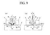
- the floorboard fixture 100 For fixing the floorboards 4 to the support members 5 in this manner, a technique in which a long channel fitting provided with flanges 101 protruding outward from upper edges of an opening is used as the floorboard fixture 100 has been proposed. Specifically, the flanges 101 of the floorboard fixture 100 are respectively inserted into the slits 41 formed in the opposing side surfaces 40 of neighboring floorboards 4, and the threaded nails 7' inserted into nail holes 102 formed in a base plate at a predetermined interval in the longitudinal direction are driven (screwed) into the support members 5, thereby fixing the floorboards 4 to the support members 5 via the floorboard fixture 100 (see Fig. 9(A) ).
- the floorboard fixture 110 which is T-shaped in cross section and has a bridge section 111 and an intermediate segment 112 protruding from the lower surface of the bridge section 111.
- the bridge section 111 of this floorboard fixture 110 is inserted into the slits 41 of the floorboards 4, and the threaded nails 7' inserted into nail holes 113 vertically extending through the intermediate segment 112 are driven (screwed) into the support members 5, thereby fixing the floorboards 4 to the support members 5 (see Fig. 9(B) ).
- engagement claws 103 having serrated edges are formed along the edges of the flanges 101, as shown in Fig. 10 , so that when performing the fixing process with the threaded nails 7', the engagement claws 103 engage with inner walls of the slits 41 in the floorboards 4 (Patent Document 1; see Fig. 10 ).
- Patent Document 1 see Fig. 10
- the floorboard fixture 110 is made to deform as the threaded nails 7' are fastened to the support members 5, whereby increased contact resistance relative to the inner walls of the slits 41 in the floorboards 4 is achieved due to this deformation (Patent Document 2; see Fig. 11 ).
- the fixing techniques using the floorboard fixtures 100 and 110 are advantageous in that the floorboards 4 can be prevented from being pulled upward, a force for restricting the movement of the floorboards 4 in the longitudinal direction is weak since the floorboards 4 and the floorboard fixture 100 or 110 are not directly connected to each other.
- the floorboards 4 may move in the longitudinal direction by a distance equivalent to the clearance every time a person walks thereon. If this causes the ends of the floorboards 4 to collide with the aforementioned crossbars, the collision would produce noise, and result in damage or deformation, such as distortion.
- the engagement claws 103 provided on the flanges 101 are brought into engagement with the inner walls of the slits 41 in the floorboards 4 so as to connect neighboring floorboards 4 to each other (paragraph [0055] in Patent Document 1).
- the floorboard fixture 100 is given a function similar to a "clamp".
- the floorboards 4 and the floorboard fixture 100 are firmly connected to each other. Consequently, when the floorboard fixture 100 is used, it is assumed that the floorboards 4 can be effectively prevented from moving in the longitudinal direction.
- a relatively large dimensional change occurs in the floorboards 4, particularly, floorboards 4 formed of synthetic wood, due to a change in temperature or the amount of moisture absorbed.
- the dimensional change is especially large in the longitudinal direction of the floorboards 4.
- the following relates to the case of a 6-meter-long synthetic wood board.
- the floorboard fixture in addition to the ability of the floorboard fixture to fix the floorboards 4 while restricting the movement thereof in response to a load applied thereto in normal use, such as when a person walks thereon, it is desirable that the floorboard fixture be able to fix the floorboards 4 while permitting the floorboards 4 to move if an applied force that makes the floorboards 4 move is large enough to break the floorboard fixture, thus such as when a dimensional change occurs in the floorboards 4 due to expansion or contraction of the floorboards 4.
- the floorboard fixture 110 is formed of a flexible material such as a resin material.
- the floorboard fixture 110 becomes deformed so that a pressing force of the bridge section 111 applied to the inner walls of the slits 41 provided in the side surfaces 40 of the floorboards 4 increases, thereby restricting the movement of the floorboards 4 in the longitudinal direction.
- the floorboards 4 are prevented from moving in response to a force applied in normal use, such as when a person walks on the floorboards 4, but when an extremely large force is applied such as when the dimensions of the floorboards 4 change due to expansion or contraction thereof, the floorboards 4 are permitted to move in accordance with this dimensional change.
- the floorboard fixture 110 in order to cause deformation of the floorboard fixture 110, the floorboard fixture 110 is formed into a complicated shape by, for example, forming a cutout in the intermediate segment 112 in a preferred embodiment or forming a thick-walled portion and a thin-walled portion in the bridge section 111.
- the heads of the threaded nails 7' need to have a diameter r that is smaller than or equal to a width W 1 of a groove formed in the floorboard fixture 100.
- the side surfaces 40 of the floorboards 4 may similarly be scraped off if the threaded nails 7' are driven slantwise.
- the present invention has been made to solve the problems in the related art, and an obj ect thereof is to provide a relatively simple-structured floorboard fixture that has a function for restricting movement of floorboards in the longitudinal direction thereof when an external force generated in normal use such as when a person walks on the floorboards is applied to the floorboards, and that permits the floorboards to move if a force that makes a contact position between the floorboard fixture and the floorboards move in the longitudinal direction is generated due to an extremely strong force, such as when a dimensional change occurs in the floorboards due to expansion and contraction thereof.
- another object of the present invention is to provide a floorboard fixture in which a fastener used for fastening the floorboard fixture to a support member has a flat-head with a maximum diameter, and in which, even when a threaded nail with such a large-diameter head is used, the construction process of the floorboard fixture can be performed without causing the head of the threaded nail to scrape off side surfaces of the floorboards in the width direction thereof, while also preventing the head of the threaded nail from protruding from the upper surfaces of the floorboards.
- a floorboard fixture 1 is configured to fix multiple (at least two) neighboring floorboards 4, 4, ... (simply referred to as "floorboards 4" hereinafter) onto a support member such as a joist by using a fastener.
- Each floorboard 4 has slits 41 and 41 that are respectively formed in side surfaces 40 serving as opposite widthwise end surfaces of the floorboard 4 and that extend, preferably continuously, in the longitudinal direction of the floorboard 4.
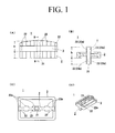
- the floorboard fixture 1 comprises a bridge section 3 having protrusions 22 and a spacer section 2 having an insertion hole 21.
- the bridge section 3 and the spacer section 2 are formed of a flexible synthetic resin material.
- the bridge section 3 is inserted into the slits 41 and 41 so as to be bridged between the two neighboring floorboards 4.
- the spacer section 2 protrudes toward the upper and lower surfaces of the floorboards from a widthwise intermediate position of the bridge section 3 so as to be interposed between the side surfaces 40 of the two neighboring floorboards 4.
- the spacer section 2 is provided with the insertion hole 21 that extends through the spacer section 2 in the aforementioned protruding direction thereof. At least one of side surfaces 23 of the spacer section 2 that are in contact with the opposing side surfaces 40 of the floorboards 4 is provided with a row of protrusions 22 or 22' that are preferably spaced apart by a predetermined distance and that extend in a direction in which the spacer section 2 is orthogonal to the longitudinal direction of the side surfaces 40.
- a fastener 7 which is a screw, a nail, or a threaded nail having a head 71 in the shape of so-called inverted conical shape (referred to as "flat-head” in this specification), i.e., a so-called flat-head screw (see Fig. 5(B) ) in the embodiments, is inserted into the insertion hole 21 of the spacer section 2.
- the flat-head 71 has a diameter that is larger than a joint width W 2 determined by the wall thickness of the spacer section 2 but smaller than a width between upper edges of chamfered portions 43 and 43 formed along corner edges of neighboring widthwise ends of upper surfaces of the floorboards 4.
- the chamfered portions 43 are at least formed at positions of the floorboards where the spacer section 2 is inserted. Moreover, a height h (see Figs. 1(A) and 1(B) ) from the lower end of the bridge section 3 to the upper end of the spacer section 2 where the insertion hole 21 is formed is substantially equal to a height H (see Fig. 5 ) from lower inner walls 41a formed within the slits 41 of the floorboards 4 to lower edges 43b of the chamfered portions 43.
- the chamfered portions 43 and 43 may at least be provided at positions where the spacer section 2 is inserted (positions where the insertion hole 21 is formed).
- the side surfaces 23 of the spacer section 2 provided with the protrusions 22 or 22' may be formed into a so-called serrated shape by forming top portions 22a of the protrusions 22 or 22' into an acute triangular shape in plan view, such that the triangular shape being arranged each of one side thereof is vertically and parrallel.
- Each of consecutively trianglular shapes has an acute angle.
- each protrusion 22 may be slanted toward one side in the width direction of the protrusion 22 (see an enlarged view in Fig. 2(D) ).
- a length 1 (see Fig. 1(A) ) from the lower end of the bridge section 3 to the lower end of the spacer section 2 may be slightly smaller than a height L (see Fig. 5 ) from the lower surfaces of the floorboards 4 to the lower inner walls 41a of the slits 41.
- the bridge section 3 and the spacer section 2 protruding in the aforementioned protruding direction from the bridge section 3 be integrally formed into the shape of a cross in cross section by using one of or multiple kinds of resin materials selected from among ABS resin, polypropylene, polyethylene, vinyl chloride, nylon, and fiberglass-reinforced polypropylene with a glass fiber length of 0.5 to 5 mm and a fiberglass content of 10 to 40 parts by weight.
- a protruding length of the bridge section 3 may be set such that the bridge section 3 does not interfere with innermost walls of the slits 41 in the floorboards 4 when the spacer section 2 is interposed between the side surfaces 40 of the floorboards 4.
- an area where the bridge section 3 comes into contact with inner surfaces of the slits 41 in the floorboards 4 be provided with a plurality of protrusions that form a row.
- the floorboard fixture 1 according to the present invention can achieve the following effects.
- the floorboard fixture 1 is formed into the shape of a cross in cross section (see Fig. 1(B) ), thereby achieving an increased contact area between the floorboard fixture 1 and the floorboards 4.
- the contact resistance between the floorboard fixture 1 and the floorboards 4 can be significantly increased.
- the contact resistance between the two can sufficiently prevent the floorboards 4 from moving in the longitudinal direction thereof in response to a force applied thereto in normal use such as when a person walks on the floorboards 4.
- a force applied thereto in normal use such as when a person walks on the floorboards 4.
- an extremely strong force that makes the contact position between the floorboards 4 and the floorboard fixture 1 move is applied such as when a dimensional change occurs in the floorboards 4 due to expansion or contraction thereof, the floorboards 4 are permitted to move.
- the floorboard fixture 1 can be prevented from breaking due to expansion or contraction of the floorboards, and the fastener 7 such as a threaded nail can be prevented from coming out, as well as preventing deformation such as warping and distortion, of the floorboards 4.
- the contact resistance between the floorboards 4 and the floorboard fixture 1 can be further increased, thereby more reliably preventing the floorboards 4 from moving in the longitudinal direction in normal use such as when a person walks on the floorboards 4.
- each protrusion 22 being slanted toward one side in the width direction of the protrusion 22, a floorboard fixture 1 that can more tightly restrict the movement of the floorboards 4 toward one side in the longitudinal direction can be provided.
- the height 1 from the lower end of the bridge section 3 to the lower end of the spacer section 2 is made slightly smaller than the height L from the lower surfaces of the floorboards 4 to the lower inner walls 41a of the slits 41 in the floorboards, when the floorboard fixture 1 is mounted onto a support member 5 by using the fastener such as a threaded nail, the lower end of the bridge section 3 is firmly pressed against the lower inner walls 41a of the slits in the floorboards, whereby the floorboards can be firmly fixed while still being permitted to move in the longitudinal direction of the floorboards when expansion or contraction occurs.
- the height h from the lower end of the bridge section 3 to the upper end of the spacer section 2 where the insertion hole is formed is set substantially equal to the height H from the lower inner walls 41a formed within the slits of the floorboards 4 to the lower edges 43b of the chamfered portions 43.
- the flat-head screw having the head 71 with a diameter r smaller than the width between upper edges 43a of neighboring chamfered portions 43 and 43 is used for fixing the floorboards to the support member.
- the flat-head screw having the flat-head 71 with the diameter r that is larger than the joint width W 2 can be used for the fixing process, thereby reducing problems like damaging a tool engagement recess formed in the head of the fastener 7 such as a threaded nail.
- the head 71 of the threaded nail 7 can be fitted into a gap between neighboring chamfered portions 43 and 43, whereby the mounting process can be performed without causing the head 71 of the fastener 7 to scrape off the side surfaces 40 of the floorboards 4, while also preventing the head 71 of the fastener 7 from protruding from the upper surfaces of the floorboards 4.
- the contact resistance relative to the floorboards 4 can be further increased, thereby more reliably preventing the floorboards 4 from moving when in normal use.
- a floorboard fixture 1 according to the present invention is formed into the shape of a cross in cross section (see Fig. 1B ) by integrally forming a bridge section 3 and a spacer section 2 which protrudes toward upper and lower surfaces of floorboards from a widthwise intermediate position of the bridge section 3, by using a synthetic resin material having flexibility, for example, ABS resin, polypropylene, polyethylene, vinyl chloride, nylon, or a synthetic resin material having both appropriate rigidity and flexibility, such as fiberglass-reinforced polypropylene with a glass fiber length of 0.5 to 5 mm and a fiberglass content of 10 to 40 parts by weight.
- a synthetic resin material having flexibility for example, ABS resin, polypropylene, polyethylene, vinyl chloride, nylon, or a synthetic resin material having both appropriate rigidity and flexibility, such as fiberglass-reinforced polypropylene with a glass fiber length of 0.5 to 5 mm and a fiberglass content of 10 to 40 parts by weight.
- the aforementioned spacer section 2 is provided with an insertion hole 21 extending through the spacer section 2 in the protruding direction thereof.
- the bridge section 3 is inserted into slits 41 formed in opposing side surfaces 40 of neighboring floorboards 4.
- a fastener in this case, a so-called flat-head screw 7 having a flat-head is inserted into the insertion hole 21 and is driven (screwed) into a support member 5, whereby the floorboard fixture 1 is fixed to the support member 5 such as a joist, and the floorboards 4 are mounted onto the support member 5 via this floorboard fixture 1 (see Figs. 5(A) and 5(B) ).
- Side surfaces 23 of the spacer section 2 of the floorboard fixture 1, which are interposed between and abut on the side surfaces 40 of the floorboards 4, are each provided with a row of protrusions 22 that are spaced apart by a predetermined distance and that extend in a direction in which the spacer section 2 is orthogonal to the longitudinal direction of the side surfaces 40.
- each side surface 23 (23a and 23b; 23c and 23d) of the spacer section 2 is provided with five protrusions 22.
- the protrusions 22 may be formed on the entire side surfaces 23 of the spacer section 2 that are in contact with the side surfaces 40 of the floorboards 4 (see Fig. 1 ) or may be partially formed thereon.
- the protrusions 22 may be formed in one of the areas (23b and 23d) of the side surfaces 23, located below the bridge section 3 (see Fig. 2 ), or in both of these areas, or may be formed in one of or both of areas 23a and 23c of the side surfaces 23, located above the bridge section 3.
- the protrusions 22 may be formed in a freely-chosen combination of the aforementioned areas of the side surfaces.
- the size of each section is adjusted so that, when the spacer section 2 is interposed between the side surfaces 40 of the floorboards 4, the top portions of the protrusions 22 on the side surface provided with the protrusions 22 abut on the side surface 40 of the corresponding floorboard 4, whereas the flat side surface not provided with the protrusions 22 abuts on the side surface 40 of the corresponding floorboard 4.
- the protrusions 22 each have a rectangular shape in plan view with a flat and relatively wide top portion 22a (see Fig. 1(C) ).
- a larger number of narrower protrusions 22 may be provided, as compared with the configuration in Fig. 1 , or the protrusions 22 may each have a triangular shape in plan view with acute top portions 22a such that the side surfaces of the spacer section 2 are entirely serrated as shown in Fig. 2 .
- the relatively wide top portions of the protrusions 22 may be provided with even finer protrusions 22', that is, protrusions 22' with acute top portions in the example shown in the drawing.
- the protrusions 22 may be formed into various kinds of shapes so long as they extend in the direction in which the spacer section 2 is orthogonal to the longitudinal direction of the floorboards 4 so as to allow for increased contact resistance relative to the side surfaces 40 of the floorboards 4.
- the protrusions 22 are preferably formed by providing protrusions 22 or 22' with acute top portions in plan view as shown in Figs. 2 and 3 , so that the side surfaces of the spacer section 2 are serrated.
- the protrusions 22 provided on the side surfaces of the spacer section 2 are to have a serrated shape by forming acute top portions 22a
- the two sides of each protrusion 22 extending from the bases thereof to the top portion 22a thereof are made as scalene sides as shown in an enlarged view in Fig. 2(D) .
- the top portions 22a of the protrusions 22 may be slanted toward one side in the width direction of the protrusions 22 by continuously arranging triangles each having one vertical side and an acute-angled side.
- the spacer section 2 is provided with the insertion hole 21 that extends through the spacer section 2 in the protruding direction thereof.
- the insertion hole 21 has a tapered upper-end portion that widens upward and another portion that has the same diameter in the entirety thereof (see Fig. 1(B) ).
- a threaded nail having a flat-head that is, a so-called flat-head screw serving as a fastener 7 to be described later
- an inclined side surface 71a formed in a head 71 of this flat-head screw is partially fitted into the tapered upper-end portion of the insertion hole 21.
- the spacer section 2 is preferably formed such that a height h (see Figs. 1(A) and 1(B) ) from the lower end of the bridge section 3 to be described later, to the upper end of the insertion hole 21 in the spacer section 2 is substantially equal to a height H (see Fig. 5(A) ) from lower inner walls 41a in the slits 41 of the floorboards 4 to lower edges 43b of chamfered portions 43 formed along opposing edges in the width direction of the upper surfaces of the floorboards.
- the chamfered portions 43 and 43 are formed along the corner edges of the upper surfaces of neighboring floorboards 4 and 4 at least at positions of the floorboards where the spacer section 2 is fitted.
- the floorboards can be fixed to the support member by using, for example, the threaded nail 7 having the flat-head 71 with a diameter r larger than the joint width W 2 between the side surfaces 40 of the floorboards 4, thereby reducing the occurrence of damage to a tool engagement recess formed in the head of the threaded nail 7 while it is being fastened.
- the flat-head 71 of the threaded nail 7 can be fitted in the gap between the chamfered portions 43 and 43 so as to be prevented from protruding from the upper surfaces of the floorboards.
- the inclined side surface 71 a formed in the head 71 of the threaded nail 7 is attached in a state where it is in contact with the chamfered portions 43 and 43 at least formed at the positions of neighboring floorboards 4 and 4 where the spacer section 2 is inserted (see Fig. 5(B) ), the contact resistance between the floorboards 4 and the floorboard fixture 1 can be further increased via the threaded nail 7 due to the contact between the inclined side surface 71a of the threaded nail 7 and the floorboards 4.
- the upper end of the spacer section 2 is entirely formed into a partly-cut-out ellipsoidal arc shape with a bulging center such that the upper side is high at the center and decreases in height toward opposite widthwise ends as shown in a front view in Fig. 1(A) .
- the shape of the floorboard fixture 1 is not limited to this.
- the upper end of the spacer section 2 may have the same height at all positions, or may be formed into, for example, a trapezoidal shape with a high central portion and low opposite widthwise ends.
- the area corresponding to the tapered upper portion of the insertion hole in Fig. 1(B) may be entirely or partially cut out so that the central portion is depressed, as shown in Fig. 2(A) .
- the opposite widthwise ends of the spacer section 2 may be provided with V-shaped deformable portions 24 that extend outward from the end edges of the spacer section 2 as shown in Fig. 4 as an example.
- Each deformable portion 24 may have a maximum width that is larger than the wall thickness of the spacer section 2 prior to the mounting process of the floorboard fixture 1, but has deformability to a degree that the deformable portion 24 deforms during the mounting process so as to not restrict the interposed contact of the side surfaces 40 of the floorboards 4 with the side surfaces of the spacer section 2.
- the spacer section 2 having the above-described configuration intersects the bridge section 3 at the center of the bridge section 3 in the width direction thereof, which is substantially rectangular in plan view, so that the floorboard fixture 1 has the shape of a cross overall as shown in a cross-sectional view in Fig. 1(B) .
- the bridge section 3 may have a flat shape with a constant thickness over the entirety thereof, as shown in Fig. 2 , so long as it can be fitted into the slits 41 formed in the side surfaces 40 of the floorboards 4.
- the bridge section 3 may have ribs along the peripheral edges thereof as shown in Fig. 1 , or may be provided with protrusions similar to those of the spacer section described above, in areas where the bridge section 3 comes into contact with the inner surfaces of the slits 41 in the floorboards 4.
- a height 1 (see Figs. 1(A) and 1(B) ) from the lower end of the spacer section 2 to the lower end of the bridge section 3 may be substantially equal to a height L (see Fig. 5(A) ) from the lower surfaces of the floorboards 4 to the lower inner walls 41a of the slits 41 in the floorboards, it is preferable that the height 1 be slightly smaller than the height L.
- the maximum thickness of the bridge section 3, that is, the thickness of the peripheral edges of the bridge section 3 in the embodiment in Fig. 1 , may be set equal to the width of the slits 41 formed in the side surfaces 40 of the floorboards 4 so that the bridge section 3 is press-fitted into the slits 41, or may be formed smaller than the width of the slits 41 so that the bridge section 3 is loosely fitted into the slits 41.
- the bridge section 3 is formed to a size that prevents it from interfering with innermost walls of the slits 41 in the floorboards 4 when the spacer section 2 is interposed between the side surfaces 40 of the floorboards 4.
- the floorboards are fixed to the support member 5 by using the fastener 7, and are preferably fixed to the support member 5 by using a threaded nail having a flat-head, that is, a so-called flat-head screw as the fastener 7.
- the threaded nail 7 serving as the fastener for the floorboard fixture 1 is formed to be longer than the overall height of the spacer section 2 so as to ensure enough driving depth in the support member 5, and an area excluding the head 71 is formed to a thickness that allows this area to be inserted into the insertion hole 21 formed in the spacer section 2.
- the bridge section 3 is fitted into the slits 41 formed in the opposing side surfaces 40 of neighboring floorboards 4, and the spacer section 2 is interposed between the side surfaces 40 of the floorboards 4 so that the side surfaces 40 of the floorboards 4 are in contact with the side surfaces 23 of the spacer section 2.
- the distance between the floorboards 4 is adjusted with the deformation of the deformable portions 24 so that the side surfaces 40 of the floorboards 4 come into pressure contact with the side surfaces 23 of the spacer section 2.
- the joint width W 2 between the floorboards 4 is set to a fixed width based on the wall thickness of the spacer section 2 so that the floorboards 4 can be arranged neatly with the same joint width W 2 .
- the threaded nail 7 inserted in the insertion hole 21 is driven into the support member 5 so that the lower end of the spacer section 2 is pressed onto the support member 5 and the lower surface of the bridge section 3 is pressed onto the lower inner walls 41a of the slits 41 in the floorboards, whereby the floorboards 4 are fixed onto the support member 5 via the floorboard fixture 1.
- each floorboard 4 is fixed to multiple locations that are set apart by a predetermined distance, for example, about 450 mm in the longitudinal direction of the floorboard 4 in correspondence with the distance between support members 5 such as joists.
- the floorboard fixture 1 fixes the floorboards 4 based on the pressure contact between the lower surface of the aforementioned bridge section 3 and the lower inner walls 41a of the slits 41 in the floorboards and the pressure contact between the side surfaces 40 of the floorboards 4 and the side surfaces of the spacer section 2 without being directly fixed to the floorboards 4 with a nail, a threaded nail, or an adhesive
- the above-described structure of the floorboard fixture 1 allows for an increased contact area between the side surfaces 40 of the floorboards 4 and the floorboard fixture 1 since the spacer section 2 also exists above the bridge section 3, unlike the T-shaped fixture (see Fig. 9(B) ) described in the related art, thereby achieving increased contact resistance.
- the side surfaces 23 of the spacer section 2 are provided with protrusions that longitudinally extend in the vertical direction of the spacer section, that is, the protrusions 22 extending orthogonally to the longitudinal direction of the slits in the side surfaces of the floorboards 4 in the embodiment in Fig. 5 , the contact resistance between the side surfaces 23 of the spacer section 2 and the side surfaces 40 of the floorboards 4 is also increased.
- the deformable portions 24 are pressed against the side surfaces 40 of the floorboards 4 due to an elastic restoring force of the deformable portions 24, and the tips of the deformable portions 24 would move together with the floorboards if the floorboards 4 were to move in the longitudinal direction thereof. In that case, since one of the deformable portions 24 would expand outward, the contact resistance relative to the side surfaces 40 of the floorboards 4 is further increased.
- the floorboards 4 are permitted to move since the floorboards 4 and the floorboard fixture 1 are not directly fastened to each other with a nail, a threaded nail, or an adhesive, as described above.
- the floorboard fixture 1 can be prevented from breaking and the threaded nail 7 that fixes the floorboard fixture 1 to the support member 5 can be prevented from coming out, as well as preventing deformation such as warping and distortion of the floorboards 4.
- a force applied by the floorboard fixture 1 for restricting the movement of the floorboards 4 is stronger in a case where the floorboards 4 moving in a direction indicated by an arrow A in Fig. 6(A) are to be restricted, as compared with a case where the floorboards 4 moving in a direction indicated by an arrow B in Fig. 6(B) are to be restricted.
- floorboard fixtures 1 (1a to 1d) may be alternately arranged facing opposite directions at a predetermined interval in the longitudinal direction of the floorboards 4, so that the floorboard fixtures 1a and 1c tightly restrict the movement of the floorboards 4 when moving in the direction of the arrow (A) in Fig. 6(A) , whereas the floorboard fixtures 1b and 1d tightly restrict the movement of the floorboards 4 when moving in the direction of the arrow (B) in Fig. 6(B) , thereby preventing the floorboards 4 from moving toward either side in the longitudinal direction.
- floorboard fixtures 1 (1a and 1b) may be mounted such that a large force for restricting the movement of the floorboard 4 acts in a direction away from the crossbar. With this configuration, the one end of the floorboard 4 is always maintained in abutment with the crossbar.
- Fig. 6(E) if the floorboard 4 in a position where one end thereof has moved away from the crossbar deforms and expands so as to become larger in size, the force for restricting the movement is weaker in the floorboard fixture 1a than in the floorboard fixture 1b. Therefore, the floorboard 4 expands so as to bring the crossbar-side end thereof closer toward the crossbar as indicated by a dashed line in Fig. 6(E) .
- the floorboard 4 contracts so as to become smaller in size, because the restricting force is weaker in the floorboard fixture 1b than in the floorboard fixture 1a, the floorboard deforms so as to contract its right end in the drawing, whereby the floorboard 4 can automatically return to its original position (i.e., the position at the time of construction) where the floorboard 4 is butted against the crossbar in accordance with the expansion or contraction of the floorboard 4.
Landscapes
- Engineering & Computer Science (AREA)
- Architecture (AREA)
- Civil Engineering (AREA)
- Structural Engineering (AREA)
- Physics & Mathematics (AREA)
- Electromagnetism (AREA)
- Floor Finish (AREA)
Abstract
Description
- The present invention relates to a floorboard fixing device for fixing floorboards (hereinafter called "floorboard fixture") used indoors or outdoors as for example, wooden decks or floors and each having slits that are formed in side surfaces located at opposite widthwise ends and that extend in the longitudinal direction of the floorboard, onto support members such as joists, by using fasteners such as screws, nails, or threaded nails, and particularly to a floorboard fixture suitable for fixing floorboards formed of synthetic wood based on a method according to Japanese Patent No.
3,543,021 - With reference to a wooden deck as an example, as shown in
Fig. 7 , a wooden-deck construction process involves, for example, settingposts 6 upright on an installation surface 9 serving as a foundation formed by pouring concrete on the ground as needed, settingsupport members 5 such as joists on theposts 6, arranging deck panels serving asfloorboards 4 parallel to each other in a certain direction at a predetermined interval on thesupport members 5, and fixing thefloorboards 4 to thesupport members 5. - The simplest technique for fixing the
floorboards 4 to thesupport members 5 involves driving fasteners such as nails or threaded nails 7' which extend from the upper surfaces of thefloorboards 4 to thesupport members 5 so as to directly fix thefloorboards 4 to thesupport members 5 with these nails or threaded nails, as shown inFig. 8 . - However, with this technique, the upper surfaces of the
floorboards 4 have a poor appearance since the heads of the nails or threaded nails 7' are exposed thereon, and if the heads of the fasteners such as the nails or threaded nails protrude from the upper surfaces of thefloorboards 4 due to aging, there is a risk of danger to people walking on the floorboards. - Furthermore, if the
floorboards 4 once constructed are to be removed, holes formed by the nails or threaded nails would remain on the upper surfaces of thefloorboards 4. Therefore, if used floorboards collected from, for example, a demolished house or the like are to be reused, a troublesome process of filling in these holes is necessary. - In light of this, techniques for mounting the
floorboards 4 to thesupport members 5 by usingfloorboard fixtures floorboards 4 have been proposed as shown inFigs. 9(A) and 9(B) . In order to allow for mounting using such afloorboard fixture side surfaces 40 serving as opposite widthwise ends of eachfloorboard 4 are provided withslits 41 that extend continuously in the longitudinal direction of thefloorboard 4. By fixing thefloorboard fixture slits 41 to thesupport members 5, thefloorboards 4 can be fixed to thesupport members 5. - For fixing the
floorboards 4 to thesupport members 5 in this manner, a technique in which a long channel fitting provided withflanges 101 protruding outward from upper edges of an opening is used as thefloorboard fixture 100 has been proposed. Specifically, theflanges 101 of thefloorboard fixture 100 are respectively inserted into theslits 41 formed in theopposing side surfaces 40 of neighboringfloorboards 4, and the threaded nails 7' inserted intonail holes 102 formed in a base plate at a predetermined interval in the longitudinal direction are driven (screwed) into thesupport members 5, thereby fixing thefloorboards 4 to thesupport members 5 via the floorboard fixture 100 (seeFig. 9(A) ). Another proposed technique uses thefloorboard fixture 110 which is T-shaped in cross section and has abridge section 111 and anintermediate segment 112 protruding from the lower surface of thebridge section 111. Specifically, thebridge section 111 of thisfloorboard fixture 110 is inserted into theslits 41 of thefloorboards 4, and the threaded nails 7' inserted intonail holes 113 vertically extending through theintermediate segment 112 are driven (screwed) into thesupport members 5, thereby fixing thefloorboards 4 to the support members 5 (seeFig. 9(B) ). - As another proposed example, in the structure of the
floorboard fixture 100 described with reference toFig. 9(A) ,engagement claws 103 having serrated edges are formed along the edges of theflanges 101, as shown inFig. 10 , so that when performing the fixing process with the threaded nails 7', theengagement claws 103 engage with inner walls of theslits 41 in the floorboards 4 (Patent Document 1; seeFig. 10 ). Furthermore, as another proposed example, in the structure of thefloorboard fixture 110 described with reference toFig. 9(B) , thefloorboard fixture 110 is made to deform as the threaded nails 7' are fastened to thesupport members 5, whereby increased contact resistance relative to the inner walls of theslits 41 in thefloorboards 4 is achieved due to this deformation (Patent Document 2; seeFig. 11 ). -
- Patent Document 1: Japanese Unexamined Patent Application Publication No.
2002-146901 - Patent Document 2: Japanese Unexamined Patent Application Publication No.
2008-285929 - Patent Document 3: Japanese Unexamined Patent Application Publication No.
2008-255601 - Patent Document 4: Japanese Unexamined Patent Application Publication No.
2008-031827 - Patent Document 5: Japanese Unexamined Patent Application Publication No.
2006-226029 - Patent Document 6: Publication of Japanese Registered Utility Model No.
3091481 - In the above-described techniques for fixing the
floorboards 4, even if thefloorboards 4 are pulled upward away from thesupport members 5, thefloorboards 4 are kept fixed on thesupport members 5 and cannot be pulled off since the inner walls of theslits 41 formed in theside surfaces 40 of thefloorboards 4 are in contact with theflanges 101 or thebridge section 111 of thefloorboard fixture Figs. 9(A) and 9(B) . - Although the fixing techniques using the
floorboard fixtures floorboards 4 can be prevented from being pulled upward, a force for restricting the movement of thefloorboards 4 in the longitudinal direction is weak since thefloorboards 4 and thefloorboard fixture - For this reason, when a force that causes the
floorboards 4 to move in the longitudinal direction is applied thereto due to, for example, a person walking on thefloorboards 4 fixed in this manner, there is a possibility that the floorboards may move in the longitudinal direction and become detached. Therefore, it is necessary to provide crossbars or the like in abutment with opposite longitudinal ends of thefloorboards 4 so as to restrict the movement of thefloorboards 4. - However, even if the crossbars are provided in this manner to prevent the ends of the
floorboards 4 from moving beyond the crossbars, since it is necessary to provide a small clearance between the ends of thefloorboards 4 and the crossbars in view of expansion and contraction of thefloorboards 4 caused by changes in temperature and/or humidity, thefloorboards 4 may move in the longitudinal direction by a distance equivalent to the clearance every time a person walks thereon. If this causes the ends of thefloorboards 4 to collide with the aforementioned crossbars, the collision would produce noise, and result in damage or deformation, such as distortion. - In the
floorboard fixture 100 discussed inPatent Document 1 shown inFig. 10 , theengagement claws 103 provided on theflanges 101 are brought into engagement with the inner walls of theslits 41 in thefloorboards 4 so as to connect neighboringfloorboards 4 to each other (paragraph [0055] in Patent Document 1). With theengagement claws 103, thefloorboard fixture 100 is given a function similar to a "clamp". By providing theseengagement claws 103 and engaging them with thefloorboards 4, thefloorboards 4 and thefloorboard fixture 100 are firmly connected to each other. Consequently, when thefloorboard fixture 100 is used, it is assumed that thefloorboards 4 can be effectively prevented from moving in the longitudinal direction. - However, a relatively large dimensional change occurs in the
floorboards 4, particularly,floorboards 4 formed of synthetic wood, due to a change in temperature or the amount of moisture absorbed. The dimensional change is especially large in the longitudinal direction of thefloorboards 4. For example, the following relates to the case of a 6-meter-long synthetic wood board. - Coefficient of Linear Expansion
4.4 x 10⁻⁵ (°C-1) Measurement Temperature Range: -10°C~90°C (JIS K 7197 Compliance) - Expansion Length of 6-meter-long board (ΔL):
ΔL=5.28mm (20°C→40°C : in case of Temperature Difference (ΔT)=20°C
ΔL=10.56mm (20°C→60°C : in case of ΔT=40°C)
- Therefore, if the
floorboards 4 and thefloorboard fixture 100 are firmly connected to each other by bringing theengagement claws 103 into engagement with thefloorboards 4, as in thefloorboard fixture 100 inFig. 10 , the dimensional change in thefloorboards 4 caused by expansion or contraction cannot be absorbed. Thus, when a large force is applied to thefloorboard fixture 100, causing thefloorboard fixture 100 to break or deform and the threaded nails 7' to come out, there is a possibility that thefloorboards 4 cannot be fixed in position, and that deformation such as warping and distortion may occur in thefloorboards 4. - Therefore, in addition to the ability of the floorboard fixture to fix the
floorboards 4 while restricting the movement thereof in response to a load applied thereto in normal use, such as when a person walks thereon, it is desirable that the floorboard fixture be able to fix thefloorboards 4 while permitting thefloorboards 4 to move if an applied force that makes thefloorboards 4 move is large enough to break the floorboard fixture, thus such as when a dimensional change occurs in thefloorboards 4 due to expansion or contraction of thefloorboards 4. - To meet this demand, in the
floorboard fixture 110 discussed inPatent Document 2 described above with reference toFig. 11 , thefloorboard fixture 110 is formed of a flexible material such as a resin material. Thus, by driving the threaded nails 7', thefloorboard fixture 110 becomes deformed so that a pressing force of thebridge section 111 applied to the inner walls of theslits 41 provided in theside surfaces 40 of thefloorboards 4 increases, thereby restricting the movement of thefloorboards 4 in the longitudinal direction. Consequently, thefloorboards 4 are prevented from moving in response to a force applied in normal use, such as when a person walks on thefloorboards 4, but when an extremely large force is applied such as when the dimensions of thefloorboards 4 change due to expansion or contraction thereof, thefloorboards 4 are permitted to move in accordance with this dimensional change. - However, with regard to the
floorboard fixture 110 discussed inPatent Document 2 mentioned above, in order to cause deformation of thefloorboard fixture 110, thefloorboard fixture 110 is formed into a complicated shape by, for example, forming a cutout in theintermediate segment 112 in a preferred embodiment or forming a thick-walled portion and a thin-walled portion in thebridge section 111. - With regard to the
floorboard fixture 100 described with reference toFigs. 9(A) and10 , in order for the heads of the threaded nails 7' to be hidden within the gaps formed between thefloorboards 4, the heads of the threaded nails 7' need to have a diameter r that is smaller than or equal to a width W1 of a groove formed in thefloorboard fixture 100. In thefloorboard fixture 110 described with reference toFigs. 9(B) and11 , it is necessary to use threaded nails whose heads have a diameter r that is smaller than or equal to a distance (referred to as "joint width" hereinafter) W2 between theside surfaces 40 of neighboringfloorboards 4. - Therefore, if the joint width W2 of the
floorboards 4 is to be made relatively narrow, the diameter r of the heads of the threaded nails 7' to be used is inevitably reduced. For this reason, a tool engagement recess formed in each head may become deformed due to torque from a tool such as a screwdriver, resulting in an inability to fasten the threaded nail 7'. - On the other hand, in the technique for fixing the
floorboards 4 described with reference toFigs. 9(B) and11 , if threaded nails with heads having a diameter r larger than the joint width W2 are purposely used, the heads of the threaded nails 7' would scrape off theside surfaces 40 of thefloorboards 4 when fastening the threaded nails 7', resulting in a poor appearance after the construction process. Mending these areas scraped off by the heads of the threaded nails 7' by filling these areas with putty or the like to enhance the appearance requires many hours of labor. - Even in a case where the threaded nails 7' used have heads with a diameter smaller than the joint width, the
side surfaces 40 of thefloorboards 4 may similarly be scraped off if the threaded nails 7' are driven slantwise. - The present invention has been made to solve the problems in the related art, and an obj ect thereof is to provide a relatively simple-structured floorboard fixture that has a function for restricting movement of floorboards in the longitudinal direction thereof when an external force generated in normal use such as when a person walks on the floorboards is applied to the floorboards, and that permits the floorboards to move if a force that makes a contact position between the floorboard fixture and the floorboards move in the longitudinal direction is generated due to an extremely strong force, such as when a dimensional change occurs in the floorboards due to expansion and contraction thereof.
- In addition to the aforementioned object, another object of the present invention is to provide a floorboard fixture in which a fastener used for fastening the floorboard fixture to a support member has a flat-head with a maximum diameter, and in which, even when a threaded nail with such a large-diameter head is used, the construction process of the floorboard fixture can be performed without causing the head of the threaded nail to scrape off side surfaces of the floorboards in the width direction thereof, while also preventing the head of the threaded nail from protruding from the upper surfaces of the floorboards.
- Means for solving the problems will be described below using reference numerals used in embodiments of the invention. It is to be noted that these reference numerals are only provided for clarifying the correspondence relationship between the scope of the claims and the embodiments of the invention, but should not be used for limiting the interpretation of the technical scope of the claims of the present invention.
- In order to achieve the aforementioned objects, a
floorboard fixture 1 according to the present invention is configured to fix multiple (at least two) neighboringfloorboards floorboards 4" hereinafter) onto a support member such as a joist by using a fastener. Eachfloorboard 4 hasslits side surfaces 40 serving as opposite widthwise end surfaces of thefloorboard 4 and that extend, preferably continuously, in the longitudinal direction of thefloorboard 4. - The
floorboard fixture 1 comprises abridge section 3 havingprotrusions 22 and aspacer section 2 having aninsertion hole 21. Thebridge section 3 and thespacer section 2 are formed of a flexible synthetic resin material. Thebridge section 3 is inserted into theslits floorboards 4. - The
spacer section 2 protrudes toward the upper and lower surfaces of the floorboards from a widthwise intermediate position of thebridge section 3 so as to be interposed between the side surfaces 40 of the two neighboringfloorboards 4. - The
spacer section 2 is provided with theinsertion hole 21 that extends through thespacer section 2 in the aforementioned protruding direction thereof. At least one of side surfaces 23 of thespacer section 2 that are in contact with the opposing side surfaces 40 of thefloorboards 4 is provided with a row ofprotrusions 22 or 22' that are preferably spaced apart by a predetermined distance and that extend in a direction in which thespacer section 2 is orthogonal to the longitudinal direction of the side surfaces 40. - Furthermore, a
fastener 7 which is a screw, a nail, or a threaded nail having ahead 71 in the shape of so-called inverted conical shape (referred to as "flat-head" in this specification), i.e., a so-called flat-head screw (seeFig. 5(B) ) in the embodiments, is inserted into theinsertion hole 21 of thespacer section 2. The flat-head 71 has a diameter that is larger than a joint width W2 determined by the wall thickness of thespacer section 2 but smaller than a width between upper edges ofchamfered portions floorboards 4. Thechamfered portions 43 are at least formed at positions of the floorboards where thespacer section 2 is inserted. Moreover, a height h (seeFigs. 1(A) and 1(B) ) from the lower end of thebridge section 3 to the upper end of thespacer section 2 where theinsertion hole 21 is formed is substantially equal to a height H (seeFig. 5 ) from lowerinner walls 41a formed within theslits 41 of thefloorboards 4 tolower edges 43b of the chamferedportions 43. - As mentioned above, the chamfered
portions spacer section 2 is inserted (positions where theinsertion hole 21 is formed). - In the
floorboard fixture 1 having the above-described configuration, the side surfaces 23 of thespacer section 2 provided with theprotrusions 22 or 22' may be formed into a so-called serrated shape by formingtop portions 22a of theprotrusions 22 or 22' into an acute triangular shape in plan view, such that the triangular shape being arranged each of one side thereof is vertically and parrallel. Each of consecutively trianglular shapes has an acute angle. - Furthermore, if the
protrusions 22 or 22' are provided with the acutetop portions 22a in this manner, thetop portion 22a of eachprotrusion 22 may be slanted toward one side in the width direction of the protrusion 22 (see an enlarged view inFig. 2(D) ). - Furthermore, a length 1 (see
Fig. 1(A) ) from the lower end of thebridge section 3 to the lower end of thespacer section 2 may be slightly smaller than a height L (seeFig. 5 ) from the lower surfaces of thefloorboards 4 to the lowerinner walls 41a of theslits 41. - It is preferable that the
bridge section 3 and thespacer section 2 protruding in the aforementioned protruding direction from thebridge section 3 be integrally formed into the shape of a cross in cross section by using one of or multiple kinds of resin materials selected from among ABS resin, polypropylene, polyethylene, vinyl chloride, nylon, and fiberglass-reinforced polypropylene with a glass fiber length of 0.5 to 5 mm and a fiberglass content of 10 to 40 parts by weight. - Furthermore, a protruding length of the
bridge section 3 may be set such that thebridge section 3 does not interfere with innermost walls of theslits 41 in thefloorboards 4 when thespacer section 2 is interposed between the side surfaces 40 of thefloorboards 4. - It is preferable that an area where the
bridge section 3 comes into contact with inner surfaces of theslits 41 in thefloorboards 4 be provided with a plurality of protrusions that form a row. - With the configuration of the present invention described above, the
floorboard fixture 1 according to the present invention can achieve the following effects. - By providing the
spacer section 2 interposed between the side surfaces 40 of thefloorboards 4 not only at the lower side of thebridge section 3 but also at the upper side thereof, thefloorboard fixture 1 is formed into the shape of a cross in cross section (seeFig. 1(B) ), thereby achieving an increased contact area between thefloorboard fixture 1 and thefloorboards 4. In addition, by providing themultiple protrusions 22 in the side surfaces 23 of thespacer section 2, the contact resistance between thefloorboard fixture 1 and thefloorboards 4 can be significantly increased. - Consequently, without having to directly fix the
floorboards 4 and thefloorboard fixture 1 to each other, the contact resistance between the two can sufficiently prevent thefloorboards 4 from moving in the longitudinal direction thereof in response to a force applied thereto in normal use such as when a person walks on thefloorboards 4. On the other hand, when an extremely strong force that makes the contact position between thefloorboards 4 and thefloorboard fixture 1 move is applied such as when a dimensional change occurs in thefloorboards 4 due to expansion or contraction thereof, thefloorboards 4 are permitted to move. Thus, thefloorboard fixture 1 can be prevented from breaking due to expansion or contraction of the floorboards, and thefastener 7 such as a threaded nail can be prevented from coming out, as well as preventing deformation such as warping and distortion, of thefloorboards 4. - In the configuration in which the side surfaces 23 of the
spacer section 2 are serrated by providing theprotrusions 22 or 22' with the acutetop portions 22a in plan view of thefloorboard fixture 1, the contact resistance between thefloorboards 4 and thefloorboard fixture 1 can be further increased, thereby more reliably preventing thefloorboards 4 from moving in the longitudinal direction in normal use such as when a person walks on thefloorboards 4. - In particular, with the
top portion 22a of eachprotrusion 22 being slanted toward one side in the width direction of theprotrusion 22, afloorboard fixture 1 that can more tightly restrict the movement of thefloorboards 4 toward one side in the longitudinal direction can be provided. - In the case where the
height 1 from the lower end of thebridge section 3 to the lower end of thespacer section 2 is made slightly smaller than the height L from the lower surfaces of thefloorboards 4 to the lowerinner walls 41a of theslits 41 in the floorboards, when thefloorboard fixture 1 is mounted onto asupport member 5 by using the fastener such as a threaded nail, the lower end of thebridge section 3 is firmly pressed against the lowerinner walls 41a of the slits in the floorboards, whereby the floorboards can be firmly fixed while still being permitted to move in the longitudinal direction of the floorboards when expansion or contraction occurs. - Relative to the
floorboards 4 provided with the chamferedportions 43 that are at least provided at the positions of the floorboards where thespacer section 2 is inserted and that are formed by chamfering the corner edges of the widthwise ends of the upper surfaces of the neighboringfloorboards bridge section 3 to the upper end of thespacer section 2 where the insertion hole is formed is set substantially equal to the height H from the lowerinner walls 41a formed within the slits of thefloorboards 4 to thelower edges 43b of the chamferedportions 43. Moreover, in the process for fixing thefloorboard fixture 1 to thesupport member 5, the flat-head screw having thehead 71 with a diameter r smaller than the width betweenupper edges 43a of neighboring chamferedportions head 71 with the diameter r that is larger than the joint width W2 can be used for the fixing process, thereby reducing problems like damaging a tool engagement recess formed in the head of thefastener 7 such as a threaded nail. - Furthermore, when the floorboards are to be fixed to the support member by using the
fastener 7 such as a threaded nail having a flat-head, whose head has a diameter r that is larger than the joint width W2, thehead 71 of the threadednail 7 can be fitted into a gap between neighboringchamfered portions head 71 of thefastener 7 to scrape off the side surfaces 40 of thefloorboards 4, while also preventing thehead 71 of thefastener 7 from protruding from the upper surfaces of thefloorboards 4. - In addition, with an
inclined side surface 71a of thehead 71 of thefastener 7 being in contact with the chamferedportions floorboards 4 can be further increased, thereby more reliably preventing thefloorboards 4 from moving when in normal use. - The objects and advantages of the present invention will become apparent from a detailed description of preferred embodiments based on the appended drawings using reference numerals that denote respective components.
-
Fig. 1 illustrates a floorboard fixture according to an embodiment of the present invention, and includes a front view (A), a cross-sectional view (B) taken along line B-B in view (A), a plan view (C), and a perspective view (D); -
Fig. 2 illustrates a floorboard fixture according to another embodiment of the present invention, and includes a front view (A), a side view (B), a plan view (C), and a bottom view (D); -
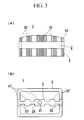
Fig. 3 illustrates a modification of the floorboard fixture inFig. 1 , and includes a front view (A) and a bottom view (B); -
Fig. 4 illustrates another modification of the floorboard fixture inFig. 1 , and includes a front view (A) and a bottom view (B); -
Fig. 5 illustrates the floorboard fixture according to the present invention in use, and includes a diagram (A) showing a threaded nail serving as a fastener before being driven and a diagram (B) showing the threaded nail in a driven state; -
Fig. 6 illustrates the floorboard fixture inFig. 2 , and includes diagrams (A) and (B) showing different moving directions of a floorboard and different effects of protrusions, a diagram (C) showing a construction example of floorboard fixtures, and diagrams (D) to (F) showing the effects of another construction example of floorboard fixtures; -
Fig. 7 illustrates how floorboards are normally constructed; -
Fig. 8 illustrates how floorboards are fixed (by using nails) in the related art; -
Fig. 9 illustrates floorboard fixing techniques in the related art, and includes a diagram (A) showing an example in which a flanged channel fitting is used as a floorboard fixture and a diagram (B) showing an example in which a T-shaped floorboard fixture is used; -
Fig. 10 is a perspective view of a floorboard fixture in the related art (corresponding toFig. 8(a) in Patent Document 1); and -
Fig. 11 illustrates a principle of how floorboards are fixed using the floorboard fixture in the related art (corresponding toFig. 10(B) in Patent Document 2). - Embodiments of the present invention will be described below with reference to the appended drawings.
- A
floorboard fixture 1 according to the present invention is formed into the shape of a cross in cross section (seeFig. 1B ) by integrally forming abridge section 3 and aspacer section 2 which protrudes toward upper and lower surfaces of floorboards from a widthwise intermediate position of thebridge section 3, by using a synthetic resin material having flexibility, for example, ABS resin, polypropylene, polyethylene, vinyl chloride, nylon, or a synthetic resin material having both appropriate rigidity and flexibility, such as fiberglass-reinforced polypropylene with a glass fiber length of 0.5 to 5 mm and a fiberglass content of 10 to 40 parts by weight. - The
aforementioned spacer section 2 is provided with aninsertion hole 21 extending through thespacer section 2 in the protruding direction thereof. Thebridge section 3 is inserted intoslits 41 formed in opposing side surfaces 40 of neighboring floorboards 4. In a state where thespacer section 2 is interposed between the side surfaces 40 of thefloorboards 4 such that the floorboards are arranged with a fixed joint width W2 therebetween, a fastener, in this case, a so-called flat-head screw 7 having a flat-head is inserted into theinsertion hole 21 and is driven (screwed) into asupport member 5, whereby thefloorboard fixture 1 is fixed to thesupport member 5 such as a joist, and thefloorboards 4 are mounted onto thesupport member 5 via this floorboard fixture 1 (seeFigs. 5(A) and 5(B) ). - Side surfaces 23 of the
spacer section 2 of thefloorboard fixture 1, which are interposed between and abut on the side surfaces 40 of thefloorboards 4, are each provided with a row ofprotrusions 22 that are spaced apart by a predetermined distance and that extend in a direction in which thespacer section 2 is orthogonal to the longitudinal direction of the side surfaces 40. In an embodiment shown inFig. 1 , each side surface 23 (23a and 23b; 23c and 23d) of thespacer section 2 is provided with fiveprotrusions 22. - The
protrusions 22 may be formed on the entire side surfaces 23 of thespacer section 2 that are in contact with the side surfaces 40 of the floorboards 4 (seeFig. 1 ) or may be partially formed thereon. For example, theprotrusions 22 may be formed in one of the areas (23b and 23d) of the side surfaces 23, located below the bridge section 3 (seeFig. 2 ), or in both of these areas, or may be formed in one of or both ofareas bridge section 3. Furthermore, theprotrusions 22 may be formed in a freely-chosen combination of the aforementioned areas of the side surfaces. - If the
protrusions 22 are to be partially provided on the side surfaces 23 of thespacer section 2, the size of each section is adjusted so that, when thespacer section 2 is interposed between the side surfaces 40 of thefloorboards 4, the top portions of theprotrusions 22 on the side surface provided with theprotrusions 22 abut on theside surface 40 of thecorresponding floorboard 4, whereas the flat side surface not provided with theprotrusions 22 abuts on theside surface 40 of thecorresponding floorboard 4. - In the embodiment shown in
Fig. 1 , theprotrusions 22 each have a rectangular shape in plan view with a flat and relatively widetop portion 22a (seeFig. 1(C) ). Alternatively, a larger number ofnarrower protrusions 22 may be provided, as compared with the configuration inFig. 1 , or theprotrusions 22 may each have a triangular shape in plan view with acutetop portions 22a such that the side surfaces of thespacer section 2 are entirely serrated as shown inFig. 2 . As a further alternative, referring toFig. 3 , the relatively wide top portions of theprotrusions 22 may be provided with even finer protrusions 22', that is, protrusions 22' with acute top portions in the example shown in the drawing. Theprotrusions 22 may be formed into various kinds of shapes so long as they extend in the direction in which thespacer section 2 is orthogonal to the longitudinal direction of thefloorboards 4 so as to allow for increased contact resistance relative to the side surfaces 40 of thefloorboards 4. - In order to achieve such increased contact resistance, the
protrusions 22 are preferably formed by providingprotrusions 22 or 22' with acute top portions in plan view as shown inFigs. 2 and3 , so that the side surfaces of thespacer section 2 are serrated. - Furthermore, if the
protrusions 22 provided on the side surfaces of thespacer section 2 are to have a serrated shape by forming acutetop portions 22a, the two sides of eachprotrusion 22 extending from the bases thereof to thetop portion 22a thereof are made as scalene sides as shown in an enlarged view inFig. 2(D) . In other words, thetop portions 22a of theprotrusions 22 may be slanted toward one side in the width direction of theprotrusions 22 by continuously arranging triangles each having one vertical side and an acute-angled side. - The
spacer section 2 is provided with theinsertion hole 21 that extends through thespacer section 2 in the protruding direction thereof. - In the embodiment in
Fig. 1 , theinsertion hole 21 has a tapered upper-end portion that widens upward and another portion that has the same diameter in the entirety thereof (seeFig. 1(B) ). When the floorboards are fixed to the support member by using a threaded nail having a flat-head, that is, a so-called flat-head screw serving as afastener 7 to be described later, aninclined side surface 71a formed in ahead 71 of this flat-head screw is partially fitted into the tapered upper-end portion of theinsertion hole 21. - The
spacer section 2 is preferably formed such that a height h (seeFigs. 1(A) and 1(B) ) from the lower end of thebridge section 3 to be described later, to the upper end of theinsertion hole 21 in thespacer section 2 is substantially equal to a height H (seeFig. 5(A) ) from lowerinner walls 41a in theslits 41 of thefloorboards 4 tolower edges 43b ofchamfered portions 43 formed along opposing edges in the width direction of the upper surfaces of the floorboards. Thechamfered portions floorboards spacer section 2 is fitted. - With this configuration, so long as the fastener has a diameter that is smaller than a width W3 (see
Fig. 5(B) ) betweenupper edges 43a of the chamferedportions 43, the floorboards can be fixed to the support member by using, for example, the threadednail 7 having the flat-head 71 with a diameter r larger than the joint width W2 between the side surfaces 40 of thefloorboards 4, thereby reducing the occurrence of damage to a tool engagement recess formed in the head of the threadednail 7 while it is being fastened. In addition, even when the fastening process is performed using such a threadednail 7, the flat-head 71 of the threadednail 7 can be fitted in the gap between thechamfered portions - Moreover, since the inclined side surface 71 a formed in the
head 71 of the threadednail 7 is attached in a state where it is in contact with the chamferedportions floorboards spacer section 2 is inserted (seeFig. 5(B) ), the contact resistance between thefloorboards 4 and thefloorboard fixture 1 can be further increased via the threadednail 7 due to the contact between theinclined side surface 71a of the threadednail 7 and thefloorboards 4. - In the embodiment shown in
Fig. 1 , the upper end of thespacer section 2 is entirely formed into a partly-cut-out ellipsoidal arc shape with a bulging center such that the upper side is high at the center and decreases in height toward opposite widthwise ends as shown in a front view inFig. 1(A) . However, the shape of thefloorboard fixture 1 is not limited to this. Alternatively, the upper end of thespacer section 2 may have the same height at all positions, or may be formed into, for example, a trapezoidal shape with a high central portion and low opposite widthwise ends. Furthermore, the area corresponding to the tapered upper portion of the insertion hole inFig. 1(B) may be entirely or partially cut out so that the central portion is depressed, as shown inFig. 2(A) . - Furthermore, the opposite widthwise ends of the
spacer section 2 may be provided with V-shapeddeformable portions 24 that extend outward from the end edges of thespacer section 2 as shown inFig. 4 as an example. - Each
deformable portion 24 may have a maximum width that is larger than the wall thickness of thespacer section 2 prior to the mounting process of thefloorboard fixture 1, but has deformability to a degree that thedeformable portion 24 deforms during the mounting process so as to not restrict the interposed contact of the side surfaces 40 of thefloorboards 4 with the side surfaces of thespacer section 2. - The
spacer section 2 having the above-described configuration intersects thebridge section 3 at the center of thebridge section 3 in the width direction thereof, which is substantially rectangular in plan view, so that thefloorboard fixture 1 has the shape of a cross overall as shown in a cross-sectional view inFig. 1(B) . - The
bridge section 3 may have a flat shape with a constant thickness over the entirety thereof, as shown inFig. 2 , so long as it can be fitted into theslits 41 formed in the side surfaces 40 of thefloorboards 4. Alternatively, thebridge section 3 may have ribs along the peripheral edges thereof as shown inFig. 1 , or may be provided with protrusions similar to those of the spacer section described above, in areas where thebridge section 3 comes into contact with the inner surfaces of theslits 41 in thefloorboards 4. - Although a height 1 (see
Figs. 1(A) and 1(B) ) from the lower end of thespacer section 2 to the lower end of thebridge section 3 may be substantially equal to a height L (seeFig. 5(A) ) from the lower surfaces of thefloorboards 4 to the lowerinner walls 41a of theslits 41 in the floorboards, it is preferable that theheight 1 be slightly smaller than the height L. - The maximum thickness of the
bridge section 3, that is, the thickness of the peripheral edges of thebridge section 3 in the embodiment inFig. 1 , may be set equal to the width of theslits 41 formed in the side surfaces 40 of thefloorboards 4 so that thebridge section 3 is press-fitted into theslits 41, or may be formed smaller than the width of theslits 41 so that thebridge section 3 is loosely fitted into theslits 41. - The
bridge section 3 is formed to a size that prevents it from interfering with innermost walls of theslits 41 in thefloorboards 4 when thespacer section 2 is interposed between the side surfaces 40 of thefloorboards 4. - With the
floorboard fixture 1 configured as mentnioned above, the floorboards are fixed to thesupport member 5 by using thefastener 7, and are preferably fixed to thesupport member 5 by using a threaded nail having a flat-head, that is, a so-called flat-head screw as thefastener 7. - The threaded
nail 7 serving as the fastener for thefloorboard fixture 1 is formed to be longer than the overall height of thespacer section 2 so as to ensure enough driving depth in thesupport member 5, and an area excluding thehead 71 is formed to a thickness that allows this area to be inserted into theinsertion hole 21 formed in thespacer section 2. - Referring to
Figs. 5(A) and 5(B) , with regard to thefloorboard fixture 1 according to the present invention having the above-described configuration, thebridge section 3 is fitted into theslits 41 formed in the opposing side surfaces 40 of neighboringfloorboards 4, and thespacer section 2 is interposed between the side surfaces 40 of thefloorboards 4 so that the side surfaces 40 of thefloorboards 4 are in contact with the side surfaces 23 of thespacer section 2. - In the case where the
floorboard fixture 1 has thedeformable portions 24 shown inFig. 4 , the distance between thefloorboards 4 is adjusted with the deformation of thedeformable portions 24 so that the side surfaces 40 of thefloorboards 4 come into pressure contact with the side surfaces 23 of thespacer section 2. - With this process, the joint width W2 between the
floorboards 4 is set to a fixed width based on the wall thickness of thespacer section 2 so that thefloorboards 4 can be arranged neatly with the same joint width W2. - In this state, the threaded
nail 7 inserted in theinsertion hole 21 is driven into thesupport member 5 so that the lower end of thespacer section 2 is pressed onto thesupport member 5 and the lower surface of thebridge section 3 is pressed onto the lowerinner walls 41a of theslits 41 in the floorboards, whereby thefloorboards 4 are fixed onto thesupport member 5 via thefloorboard fixture 1. - In this manner, each
floorboard 4 is fixed to multiple locations that are set apart by a predetermined distance, for example, about 450 mm in the longitudinal direction of thefloorboard 4 in correspondence with the distance betweensupport members 5 such as joists. - Although the
floorboard fixture 1 fixes thefloorboards 4 based on the pressure contact between the lower surface of theaforementioned bridge section 3 and the lowerinner walls 41a of theslits 41 in the floorboards and the pressure contact between the side surfaces 40 of thefloorboards 4 and the side surfaces of thespacer section 2 without being directly fixed to thefloorboards 4 with a nail, a threaded nail, or an adhesive, the above-described structure of thefloorboard fixture 1 allows for an increased contact area between the side surfaces 40 of thefloorboards 4 and thefloorboard fixture 1 since thespacer section 2 also exists above thebridge section 3, unlike the T-shaped fixture (seeFig. 9(B) ) described in the related art, thereby achieving increased contact resistance. - In addition, since the side surfaces 23 of the
spacer section 2 are provided with protrusions that longitudinally extend in the vertical direction of the spacer section, that is, theprotrusions 22 extending orthogonally to the longitudinal direction of the slits in the side surfaces of thefloorboards 4 in the embodiment inFig. 5 , the contact resistance between the side surfaces 23 of thespacer section 2 and the side surfaces 40 of thefloorboards 4 is also increased. - Furthermore, when the floorboards are to be fixed to the support member by using the flat-
head screw 7 having thehead 71 with a diameter larger than the joint width W2 as mentioned above, in the fixing process of thefloorboard fixture 1, since theinclined side surface 71a provided in thehead 71 of the flat-head screw comes into pressure contact with the chamferedportions floorboards 4 as the flat-head screw 7 is fastened, the movement of thefloorboards 4 is restricted also by the contact resistance between theinclined side surface 71a of thehead 71 of the flat-head screw and thefloorboards 4. - Furthermore, in the configuration in which the V-shaped
deformable portions 24 are provided at the opposite widthwise ends of thespacer section 2, thedeformable portions 24 are pressed against the side surfaces 40 of thefloorboards 4 due to an elastic restoring force of thedeformable portions 24, and the tips of thedeformable portions 24 would move together with the floorboards if thefloorboards 4 were to move in the longitudinal direction thereof. In that case, since one of thedeformable portions 24 would expand outward, the contact resistance relative to the side surfaces 40 of thefloorboards 4 is further increased. - Therefore, with the
floorboards 4 and thefloorboard fixture 1 being in contact with each other, a sufficient fixation force for preventing thefloorboards 4 from moving in response to a load or force applied thereto in normal use, such as when a person walks on thefloorboards 4, is generated. - On the other hand, if the dimensions of the
floorboards 4 change due to, for example, expansion or contraction of thefloorboards 4 caused by a change in temperature or humidity, and an extremely strong force that makes the contact position between thefloorboards 4 and thefloorboard fixture 1 move is thus generated, thefloorboards 4 are permitted to move since thefloorboards 4 and thefloorboard fixture 1 are not directly fastened to each other with a nail, a threaded nail, or an adhesive, as described above. - As a result, even when such a dimensional change in the
floorboards 4 occurs due to expansion or contraction, thefloorboard fixture 1 can be prevented from breaking and the threadednail 7 that fixes thefloorboard fixture 1 to thesupport member 5 can be prevented from coming out, as well as preventing deformation such as warping and distortion of thefloorboards 4. - Referring to
Fig. 2 , in thefloorboard fixture 1 provided with theprotrusions 22 that are arranged such that the acutetop portions 22a are slanted toward one side in the width direction of theprotrusions 22, assuming that theprotrusions 22 of thefloorboard fixture 1 are in contact with the side surfaces of thefloorboards 4 as shown inFigs. 6(A) and 6(B) , a force applied by thefloorboard fixture 1 for restricting the movement of thefloorboards 4 is stronger in a case where thefloorboards 4 moving in a direction indicated by an arrow A inFig. 6(A) are to be restricted, as compared with a case where thefloorboards 4 moving in a direction indicated by an arrow B inFig. 6(B) are to be restricted. - Specifically, in the above example, when the
floorboards 4 move in the direction of the arrow A, as shown inFig. 6(A) , thetop portions 22a of theprotrusions 22 of thefloorboard fixture 1, which are formed of a flexible material, fixture are pulled by the movingfloorboards 4 so as to deform in an outwardly expanding manner, as indicated by arrows a in the drawing. As a result, the contact resistance relative to the side surfaces 40 of thefloorboards 4 increases due to the deformation of theprotrusions 22. - On the other hand, when the
floorboards 4 move in the direction of the arrow B, as shown inFig. 6(B) , thetop portions 22a of theprotrusions 22 of thefloorboard fixture 1, which are formed of a flexible material, are pulled by the movement offloorboards 4 so as to deform in an inwardly contracting manner, as indicated by arrows b in the drawing. As a result, in the case where theprotrusions 22 having the above-described shape are provided, thefloorboard fixture 1 tightly restricts the movement of thefloorboards 4 moving in the direction of the arrow A with a stronger force, as compared with thefloorboards 4 moving in the direction of the arrow B. - Accordingly, in the
floorboard fixture 1 shown inFig. 2 , the force for restricting the movement of thefloorboards 4 varies depending on the direction. Therefore, as shown inFig. 6(C) , for example, floorboard fixtures 1 (1a to 1d) may be alternately arranged facing opposite directions at a predetermined interval in the longitudinal direction of thefloorboards 4, so that thefloorboard fixtures 1a and 1c tightly restrict the movement of thefloorboards 4 when moving in the direction of the arrow (A) inFig. 6(A) , whereas thefloorboard fixtures floorboards 4 when moving in the direction of the arrow (B) inFig. 6(B) , thereby preventing thefloorboards 4 from moving toward either side in the longitudinal direction. - Furthermore, as shown in
Fig. 6(D) , for example, in a state where one longitudinal end of eachfloorboard 4 is butted against a crossbar or the like so as to restrict the movement thereof, floorboard fixtures 1 (1a and 1b) may be mounted such that a large force for restricting the movement of thefloorboard 4 acts in a direction away from the crossbar. With this configuration, the one end of thefloorboard 4 is always maintained in abutment with the crossbar. - In a case where the
floorboard 4 and the floorboard fixtures 1 (1a and 1b) are mounted as inFig. 6(D) , if by any possibility thefloorboard 4 is moved away from the crossbar due to a large unexpected force applied to thefloorboard 4, thefloorboard 4 can still automatically return to its original position where one end thereof is butted against the crossbar. - Specifically, as shown in
Fig. 6(E) , if thefloorboard 4 in a position where one end thereof has moved away from the crossbar deforms and expands so as to become larger in size, the force for restricting the movement is weaker in the floorboard fixture 1a than in thefloorboard fixture 1b. Therefore, thefloorboard 4 expands so as to bring the crossbar-side end thereof closer toward the crossbar as indicated by a dashed line inFig. 6(E) . - On the other hand, if the
floorboard 4 contracts so as to become smaller in size, because the restricting force is weaker in thefloorboard fixture 1b than in the floorboard fixture 1a, the floorboard deforms so as to contract its right end in the drawing, whereby thefloorboard 4 can automatically return to its original position (i.e., the position at the time of construction) where thefloorboard 4 is butted against the crossbar in accordance with the expansion or contraction of thefloorboard 4. - Accordingly, the scope of the following claims is not limited to the equipment, apparatus, machine, or device configured only by specific means disclosed here, or to the steps or method disclosed here. The aforementioned scope of the claims is intended to protect the core or essence of this innovative invention. The present invention apparently has novelty and is practical.
- Furthermore, at the time of conception of the present invention, the present invention was not obvious to those skilled in the art in view of the related art or is apparently a pioneering invention within the technical field in view of the revolutionary characteristics of the invention. In legal terms, the scope of the following claims must be interpreted in an extremely broad way to protect the core of the invention.
- Therefore, since the aforementioned objects clarified in the above description are efficiently achieved, and the above configuration permits modifications to some degree without departing from the scope of the invention, all of the contents included in the above description and the appended drawings should be interpreted in an exemplary manner but not in a limited manner. It is to be understood that the scope of the following claims should include all the comprehensive and inherent characteristics of the invention described here, and in linguistic aspects, all other expressions in the scope of the invention belong to the scope of the claims.
- The present invention will be described below.
-
- 1
- Floorboard fixture
- 2
- Spacer section
- 21
- Insertion hole
- 22, 22'
- Protrusions
- 22a
- Top portions
- 23(23a-23d)
- Side surfaces
- 24
- Deformable portions
- 3
- Bridge section
- 4
- Floorboards
- 40
- Side surfaces
- 41
- Slits
- 41a
- Lower inner walls
- 42
- Lower surface (of floorboard)
- 43(,43)
- Chamfered portions
- 43a
- Upper edges (of chamfered portions 43)
- 43b
- Lower edges (of chamfered portions 43)
- 5
- Support members (Joist)
- 6
- Posts
- 7, 7'
- Fastener (Threaded nails, Flat-head screw)
- 71
- Head
- 71a
- Inclined side surface
- 9
- Installation surface
- 100
- Floorboard fixture
- 101
- Flanges
- 102
- Nail holes
- 103
- Engagement claws
- 110
- Floorboard fixing device
- 111
- Bridge section
- 112
- Intermediate segment
- 113
- Nail holes
Claims (8)
- A floorboard fixture for fixing floorboards, each floorboard having slits that are formed in side surfaces thereof serving as opposite widthwise ends and that extend in a longitudinal direction, wherein
a bridge section and a spacer section are formed of a flexible synthetic resin material, the bridge section being inserted into the slits formed in the side surfaces of two neighboring floorboards so as to be bridged between the two neighboring floorboards, and the spacer section protruding toward upper and lower surfaces of the floorboards from a widthwise intermediate position of the bridge section and being interposed between the side surfaces of the two neighboring floorboards,
the spacer section is provided with an insertion hole that extends through the spacer section in a protruding direction thereof,
side surfaces of the spacer section that are in contact with the side surfaces of the floorboards are provided with a plurality of protrusions that form rows and extend orthogonally to the longitudinal direction of the side surfaces of the floorboards,
a fastener having a flat-head is inserted into the insertion hole of the spacer section, the flat-head having a diameter that is larger than a joint width determined by a wall thickness of the spacer section but smaller than a width between upper edges of chamfered portions formed along corner edges of neighboring widthwise ends of the upper surfaces of the floorboards, the chamfered portions being at least formed at positions of the floorboards where the spacer section is inserted, and
a height from a lower end of the bridge section to an upper end of the spacer section where the insertion hole is formed is substantially equal to a height from lower inner walls formed within the slits of the floorboards to lower edges of the chamfered portions. - The floorboard fixture according to Claim 1, wherein the side surfaces of the spacer section are serrated by forming top portions of the protrusions into a triangular shape in plan view, such that the triangular shape being arranged each of one side thereof is vertically and parrallel, and each of consecutively trianglular shapes has an acute angle.
- The floorboard fixture according to Claim 2, wherein the top portion of each protrusion is slanted toward one side in a width direction of the protrusion.
- The floorboard fixture according to Claim 1, wherein a length from the lower end of the bridge section to a lower end of the spacer section is slightly smaller than a height from the lower surfaces of the floorboards to the lower inner walls of the slits.
- The floorboard fixture according to Claim 1, wherein the fastener inserted into the insertion hole is a threaded nail, a nail, or a screw having a flat-head.
- The floorboard fixture according to Claim 1, wherein the bridge section and the spacer section are integrally formed into a shape of a cross in cross section by using a single kind of resin material or a mixture of multiple kinds of resin materials selected from among ABS resin, polypropylene, polyethylene, vinyl chloride, nylon, and fiberglass-reinforced polypropylene with a glass fiber length of 0.5 to 5 mm and a fiberglass content of 10 to 40 parts by weight.
- The floorboard fixture according to Claim 1, wherein a protruding length of the bridge section is set such that the bridge section does not interfere with innermost walls of the slits when the spacer section is interposed between the side surfaces of the floorboards.
- The floorboard fixture according to Claim 1, wherein an area where the bridge section comes into contact with inner surfaces of the slits in the floorboards is provided with a plurality of protrusions that form a row.
Applications Claiming Priority (2)
| Application Number | Priority Date | Filing Date | Title |
|---|---|---|---|
| JP2009238648A JP4578561B1 (en) | 2009-10-15 | 2009-10-15 | Floor board fixture |
| PCT/JP2010/065311 WO2011045992A1 (en) | 2009-10-15 | 2010-09-07 | Floorboard fixing device |
Publications (2)
| Publication Number | Publication Date |
|---|---|
| EP2489812A1 true EP2489812A1 (en) | 2012-08-22 |
| EP2489812A4 EP2489812A4 (en) | 2017-01-25 |
Family
ID=43319624
Family Applications (1)
| Application Number | Title | Priority Date | Filing Date |
|---|---|---|---|
| EP10823260.4A Withdrawn EP2489812A4 (en) | 2009-10-15 | 2010-09-07 | Floorboard fixing device |
Country Status (7)
| Country | Link |
|---|---|
| EP (1) | EP2489812A4 (en) |
| JP (1) | JP4578561B1 (en) |
| KR (1) | KR101401465B1 (en) |
| CN (1) | CN102549222B (en) |
| AU (1) | AU2010307860B2 (en) |
| IN (1) | IN2012DN02341A (en) |
| WO (1) | WO2011045992A1 (en) |
Cited By (8)
| Publication number | Priority date | Publication date | Assignee | Title |
|---|---|---|---|---|
| DE202014105889U1 (en) | 2013-12-06 | 2015-01-07 | Ulrich Reif | Mounting part for fixing of adjacent cover elements on a substructure, in particular a balcony or Tarrassenabdeckung |
| DE202015106255U1 (en) | 2015-11-18 | 2016-01-08 | Ulrich Reif | Mounting part for fixing of adjacent cover elements on a substructure, in particular a balcony or patio cover |
| WO2018087506A1 (en) * | 2016-11-09 | 2018-05-17 | Bika Products Limited | Decking clip |
| US12129663B2 (en) | 2017-08-15 | 2024-10-29 | National Nail Corp. | Hidden fastener unit and related method of use |
| US12234654B2 (en) | 2017-08-15 | 2025-02-25 | National Nail Corp. | Hidden fastener unit and related method of use |
| US12264483B2 (en) | 2017-08-15 | 2025-04-01 | National Nail Corp. | Hidden fastener unit and related method of use |
| US12297649B2 (en) | 2022-10-27 | 2025-05-13 | Primesource Building Products, Inc. | Deck clip |
| US12365065B2 (en) | 2022-08-02 | 2025-07-22 | National Nail Corp. | Clip starter guide and related method of use |
Families Citing this family (10)
| Publication number | Priority date | Publication date | Assignee | Title |
|---|---|---|---|---|
| JP6114621B2 (en) * | 2013-04-25 | 2017-04-12 | セイキ販売株式会社 | Deck material fixing structure |
| JP6283498B2 (en) * | 2013-10-30 | 2018-02-21 | エア・ウォーター・エコロッカ株式会社 | Deck material fixture |
| GB2540796A (en) * | 2015-07-28 | 2017-02-01 | Bika Products Ltd | Decking clip |
| US10113306B2 (en) | 2016-06-20 | 2018-10-30 | Simpson Strong-Tie Company Inc. | Deck board fasteners |
| USD796306S1 (en) | 2016-06-20 | 2017-09-05 | Simpson Strong-Tie Company Inc. | Deck board fastener |
| USD796305S1 (en) | 2016-06-20 | 2017-09-05 | Simpson Strong-Tie Company Inc. | Deck board fastener |
| USD792757S1 (en) | 2016-06-20 | 2017-07-25 | Simpson Strong-Tie Company Inc. | Deck board fastener |
| USD795049S1 (en) | 2016-06-20 | 2017-08-22 | Simpson Strong-Tie Company Inc. | Deck board fastener |
| JP6465512B2 (en) * | 2017-05-29 | 2019-02-06 | 積水ハウス株式会社 | Panel fixing bracket, floor structure, floor construction method |
| KR102040637B1 (en) * | 2019-02-28 | 2019-11-06 | 경동산업 주식회사 | The joint structure of joist for deckroad |
Family Cites Families (25)
| Publication number | Priority date | Publication date | Assignee | Title |
|---|---|---|---|---|
| DE3903693A1 (en) * | 1989-02-08 | 1990-08-09 | Gerhard R Schmidt Fa | Wainscoting |
| JPH0391481A (en) | 1989-08-18 | 1991-04-17 | Natl Sci Council | Manufacturing method of immobilized glucose oxidase membrane using plasma surface treatment method |
| JPH0391481U (en) * | 1990-01-06 | 1991-09-18 | ||
| JP3543021B2 (en) | 1995-02-17 | 2004-07-14 | アイン・エンジニアリング株式会社 | Extrusion molding method and apparatus for reinforced wood composite board |
| US6402415B1 (en) * | 1997-03-05 | 2002-06-11 | Eberle, Iii Harry W. | Anchoring biscuit device |
| JP2002146901A (en) | 2000-11-10 | 2002-05-22 | Sekisui Chem Co Ltd | deck |
| JP2002256685A (en) * | 2001-02-28 | 2002-09-11 | Toyo Kitchen & Living Co Ltd | Building plate and structure for fixing the same |
| CN2507627Y (en) * | 2001-11-23 | 2002-08-28 | 陈淑宾 | Flooring |
| JP4034076B2 (en) * | 2002-01-25 | 2008-01-16 | 日本総合住生活株式会社 | Floor laying method and floor repair method |
| KR100477516B1 (en) * | 2002-06-05 | 2005-03-23 | 송주제 | An assembly of the wooden floor |
| US6810633B2 (en) * | 2002-08-02 | 2004-11-02 | G. Steven Harris, Sr. | Deck board fastener |
| US7578105B2 (en) * | 2003-03-20 | 2009-08-25 | Blue Heron Enterprises, Llc | Expansion-compensating deck fastener |
| US6851884B2 (en) * | 2003-03-20 | 2005-02-08 | Blue Heron Enterprises, Llc | Decking anchor device |
| KR20030041905A (en) * | 2003-04-14 | 2003-05-27 | 윤석균 | assembling structure of floor |
| US7052200B2 (en) * | 2003-09-23 | 2006-05-30 | Harris G Steven | Resilient deck board fastener |
| JP4579711B2 (en) * | 2005-02-18 | 2010-11-10 | ナカ工業株式会社 | Non-slip for stairs |
| CA2507197A1 (en) * | 2005-05-13 | 2006-11-13 | Alain Lemieux | Floor covering with locking system |
| JP5091516B2 (en) * | 2006-06-28 | 2012-12-05 | 真俊 玉置 | Long plate material fixing structure, long plate material fixture, and long plate material |
| JP4908098B2 (en) * | 2006-07-31 | 2012-04-04 | ハンディテクノ株式会社 | Deck material fixing device |
| US7984599B2 (en) * | 2006-10-09 | 2011-07-26 | Building Materials Investment Corporation | Hidden decking fastener and related method of fastening deck boards |
| KR100777900B1 (en) * | 2007-01-29 | 2007-11-21 | 장석조 | Construction method of wooden deck structure and wooden deck |
| JP2008255601A (en) * | 2007-04-03 | 2008-10-23 | Handy Techno Kk | Structure for connecting plate material and metal frame |
| KR100874580B1 (en) * | 2007-04-12 | 2008-12-16 | 주식회사 엘지화학 | Deck Fasteners |
| JP4370345B2 (en) * | 2007-05-18 | 2009-11-25 | Wpcコーポレーション株式会社 | Floor board fixture |
| CN201276811Y (en) * | 2008-10-13 | 2009-07-22 | 上海泷晟环保科技有限公司 | Connection device for regenerated sheet material |
-
2009
- 2009-10-15 JP JP2009238648A patent/JP4578561B1/en not_active Expired - Fee Related
-
2010
- 2010-09-07 EP EP10823260.4A patent/EP2489812A4/en not_active Withdrawn
- 2010-09-07 AU AU2010307860A patent/AU2010307860B2/en not_active Ceased
- 2010-09-07 CN CN201080045446.6A patent/CN102549222B/en not_active Expired - Fee Related
- 2010-09-07 IN IN2341DEN2012 patent/IN2012DN02341A/en unknown
- 2010-09-07 KR KR1020127009756A patent/KR101401465B1/en not_active Expired - Fee Related
- 2010-09-07 WO PCT/JP2010/065311 patent/WO2011045992A1/en not_active Ceased
Non-Patent Citations (1)
| Title |
|---|
| See references of WO2011045992A1 * |
Cited By (12)
| Publication number | Priority date | Publication date | Assignee | Title |
|---|---|---|---|---|
| DE202014105889U1 (en) | 2013-12-06 | 2015-01-07 | Ulrich Reif | Mounting part for fixing of adjacent cover elements on a substructure, in particular a balcony or Tarrassenabdeckung |
| EP2899330A1 (en) | 2013-12-06 | 2015-07-29 | Ulrich Reif | Fixture for securing adjacent cover elements to a substructure, in particular a balcony or terrace cover |
| DE202015106255U1 (en) | 2015-11-18 | 2016-01-08 | Ulrich Reif | Mounting part for fixing of adjacent cover elements on a substructure, in particular a balcony or patio cover |
| WO2018087506A1 (en) * | 2016-11-09 | 2018-05-17 | Bika Products Limited | Decking clip |
| US12129663B2 (en) | 2017-08-15 | 2024-10-29 | National Nail Corp. | Hidden fastener unit and related method of use |
| US12234654B2 (en) | 2017-08-15 | 2025-02-25 | National Nail Corp. | Hidden fastener unit and related method of use |
| US12264483B2 (en) | 2017-08-15 | 2025-04-01 | National Nail Corp. | Hidden fastener unit and related method of use |
| US12607020B2 (en) | 2017-08-15 | 2026-04-21 | National Nail Corp. | Hidden fastener unit and related method of use |
| US12365065B2 (en) | 2022-08-02 | 2025-07-22 | National Nail Corp. | Clip starter guide and related method of use |
| US12297649B2 (en) | 2022-10-27 | 2025-05-13 | Primesource Building Products, Inc. | Deck clip |
| US12352054B2 (en) | 2022-10-27 | 2025-07-08 | Primesource Building Products, Inc. | Deck clip |
| US12442198B2 (en) | 2022-10-27 | 2025-10-14 | Primesource Building Products, Inc. | Deck clip |
Also Published As
| Publication number | Publication date |
|---|---|
| HK1170554A1 (en) | 2013-03-01 |
| WO2011045992A1 (en) | 2011-04-21 |
| JP4578561B1 (en) | 2010-11-10 |
| EP2489812A4 (en) | 2017-01-25 |
| JP2011084946A (en) | 2011-04-28 |
| IN2012DN02341A (en) | 2015-08-21 |
| CN102549222A (en) | 2012-07-04 |
| AU2010307860B2 (en) | 2014-03-13 |
| KR20120071399A (en) | 2012-07-02 |
| KR101401465B1 (en) | 2014-05-30 |
| AU2010307860A1 (en) | 2012-04-26 |
| CN102549222B (en) | 2015-02-25 |
Similar Documents
| Publication | Publication Date | Title |
|---|---|---|
| AU2010307860B2 (en) | Floorboard fixing device | |
| US9868147B2 (en) | Method of making composite deck clips | |
| KR100465549B1 (en) | Installation method of panel and rail-type fixing apparatus | |
| US20110123290A1 (en) | Gangable composite clip for attaching decking and method for making | |
| US6892500B2 (en) | Suspended ceiling support structure | |
| US8499512B2 (en) | Exterior wall construction product | |
| US20010015042A1 (en) | Flooring assembly and fastener therefor | |
| AU2014262380B2 (en) | A deck fastening system | |
| GB2561679A (en) | A decking clip | |
| CA2482296A1 (en) | Resilient deck board fastener | |
| CN110121582B (en) | Plank Connector | |
| KR101557419B1 (en) | A deck having reinforcement for preventing distortion of deck edge and deck install structure using the same | |
| GB2538116A (en) | Floor protector | |
| US20060107612A1 (en) | Anchoring device | |
| US12276118B2 (en) | Hidden clip for decking | |
| US9045910B2 (en) | Clip and method for the mounting of panels | |
| JP2609971B2 (en) | Fixed frame for pier in concrete formwork panel | |
| KR200287078Y1 (en) | Rail-type fixing apparatus for installing panel | |
| JPH0882013A (en) | Plate material mounting device | |
| HK1170554B (en) | Floorboard fixing device | |
| JPH09203184A (en) | Joining metal fitting | |
| GB2480618A (en) | Mezzanine tie bar fixing | |
| HK1138054A (en) | Hidden deck fastener | |
| JP2007085106A (en) | Flooring material-fixing structure | |
| JPH0729110U (en) | Metal furring |
Legal Events
| Date | Code | Title | Description |
|---|---|---|---|
| PUAI | Public reference made under article 153(3) epc to a published international application that has entered the european phase |
Free format text: ORIGINAL CODE: 0009012 |
|
| 17P | Request for examination filed |
Effective date: 20120328 |
|
| AK | Designated contracting states |
Kind code of ref document: A1 Designated state(s): AL AT BE BG CH CY CZ DE DK EE ES FI FR GB GR HR HU IE IS IT LI LT LU LV MC MK MT NL NO PL PT RO SE SI SK SM TR |
|
| DAX | Request for extension of the european patent (deleted) | ||
| RA4 | Supplementary search report drawn up and despatched (corrected) |
Effective date: 20170103 |
|
| RIC1 | Information provided on ipc code assigned before grant |
Ipc: E04F 15/02 20060101AFI20161221BHEP |
|
| 17Q | First examination report despatched |
Effective date: 20171107 |
|
| STAA | Information on the status of an ep patent application or granted ep patent |
Free format text: STATUS: THE APPLICATION IS DEEMED TO BE WITHDRAWN |
|
| 18D | Application deemed to be withdrawn |
Effective date: 20180320 |