EP2495813A1 - Crimp terminal - Google Patents
Crimp terminal Download PDFInfo
- Publication number
- EP2495813A1 EP2495813A1 EP10826680A EP10826680A EP2495813A1 EP 2495813 A1 EP2495813 A1 EP 2495813A1 EP 10826680 A EP10826680 A EP 10826680A EP 10826680 A EP10826680 A EP 10826680A EP 2495813 A1 EP2495813 A1 EP 2495813A1
- Authority
- EP
- European Patent Office
- Prior art keywords
- conductor
- press bond
- joining
- crimp
- terminal
- Prior art date
- Legal status (The legal status is an assumption and is not a legal conclusion. Google has not performed a legal analysis and makes no representation as to the accuracy of the status listed.)
- Withdrawn
Links
- 239000004020 conductor Substances 0.000 claims abstract description 158
- 239000011248 coating agent Substances 0.000 claims abstract description 32
- 238000000576 coating method Methods 0.000 claims abstract description 32
- 230000000694 effects Effects 0.000 description 3
- 238000005482 strain hardening Methods 0.000 description 2
Images


Classifications
-
- H—ELECTRICITY
- H01—ELECTRIC ELEMENTS
- H01R—ELECTRICALLY-CONDUCTIVE CONNECTIONS; STRUCTURAL ASSOCIATIONS OF A PLURALITY OF MUTUALLY-INSULATED ELECTRICAL CONNECTING ELEMENTS; COUPLING DEVICES; CURRENT COLLECTORS
- H01R4/00—Electrically-conductive connections between two or more conductive members in direct contact, i.e. touching one another; Means for effecting or maintaining such contact; Electrically-conductive connections having two or more spaced connecting locations for conductors and using contact members penetrating insulation
- H01R4/10—Electrically-conductive connections between two or more conductive members in direct contact, i.e. touching one another; Means for effecting or maintaining such contact; Electrically-conductive connections having two or more spaced connecting locations for conductors and using contact members penetrating insulation effected solely by twisting, wrapping, bending, crimping, or other permanent deformation
- H01R4/18—Electrically-conductive connections between two or more conductive members in direct contact, i.e. touching one another; Means for effecting or maintaining such contact; Electrically-conductive connections having two or more spaced connecting locations for conductors and using contact members penetrating insulation effected solely by twisting, wrapping, bending, crimping, or other permanent deformation by crimping
- H01R4/183—Electrically-conductive connections between two or more conductive members in direct contact, i.e. touching one another; Means for effecting or maintaining such contact; Electrically-conductive connections having two or more spaced connecting locations for conductors and using contact members penetrating insulation effected solely by twisting, wrapping, bending, crimping, or other permanent deformation by crimping for cylindrical elongated bodies, e.g. cables having circular cross-section
- H01R4/184—Electrically-conductive connections between two or more conductive members in direct contact, i.e. touching one another; Means for effecting or maintaining such contact; Electrically-conductive connections having two or more spaced connecting locations for conductors and using contact members penetrating insulation effected solely by twisting, wrapping, bending, crimping, or other permanent deformation by crimping for cylindrical elongated bodies, e.g. cables having circular cross-section comprising a U-shaped wire-receiving portion
- H01R4/185—Electrically-conductive connections between two or more conductive members in direct contact, i.e. touching one another; Means for effecting or maintaining such contact; Electrically-conductive connections having two or more spaced connecting locations for conductors and using contact members penetrating insulation effected solely by twisting, wrapping, bending, crimping, or other permanent deformation by crimping for cylindrical elongated bodies, e.g. cables having circular cross-section comprising a U-shaped wire-receiving portion combined with a U-shaped insulation-receiving portion
-
- H—ELECTRICITY
- H01—ELECTRIC ELEMENTS
- H01R—ELECTRICALLY-CONDUCTIVE CONNECTIONS; STRUCTURAL ASSOCIATIONS OF A PLURALITY OF MUTUALLY-INSULATED ELECTRICAL CONNECTING ELEMENTS; COUPLING DEVICES; CURRENT COLLECTORS
- H01R4/00—Electrically-conductive connections between two or more conductive members in direct contact, i.e. touching one another; Means for effecting or maintaining such contact; Electrically-conductive connections having two or more spaced connecting locations for conductors and using contact members penetrating insulation
- H01R4/10—Electrically-conductive connections between two or more conductive members in direct contact, i.e. touching one another; Means for effecting or maintaining such contact; Electrically-conductive connections having two or more spaced connecting locations for conductors and using contact members penetrating insulation effected solely by twisting, wrapping, bending, crimping, or other permanent deformation
- H01R4/18—Electrically-conductive connections between two or more conductive members in direct contact, i.e. touching one another; Means for effecting or maintaining such contact; Electrically-conductive connections having two or more spaced connecting locations for conductors and using contact members penetrating insulation effected solely by twisting, wrapping, bending, crimping, or other permanent deformation by crimping
- H01R4/188—Electrically-conductive connections between two or more conductive members in direct contact, i.e. touching one another; Means for effecting or maintaining such contact; Electrically-conductive connections having two or more spaced connecting locations for conductors and using contact members penetrating insulation effected solely by twisting, wrapping, bending, crimping, or other permanent deformation by crimping having an uneven wire-receiving surface to improve the contact
-
- H—ELECTRICITY
- H01—ELECTRIC ELEMENTS
- H01R—ELECTRICALLY-CONDUCTIVE CONNECTIONS; STRUCTURAL ASSOCIATIONS OF A PLURALITY OF MUTUALLY-INSULATED ELECTRICAL CONNECTING ELEMENTS; COUPLING DEVICES; CURRENT COLLECTORS
- H01R4/00—Electrically-conductive connections between two or more conductive members in direct contact, i.e. touching one another; Means for effecting or maintaining such contact; Electrically-conductive connections having two or more spaced connecting locations for conductors and using contact members penetrating insulation
- H01R4/10—Electrically-conductive connections between two or more conductive members in direct contact, i.e. touching one another; Means for effecting or maintaining such contact; Electrically-conductive connections having two or more spaced connecting locations for conductors and using contact members penetrating insulation effected solely by twisting, wrapping, bending, crimping, or other permanent deformation
- H01R4/18—Electrically-conductive connections between two or more conductive members in direct contact, i.e. touching one another; Means for effecting or maintaining such contact; Electrically-conductive connections having two or more spaced connecting locations for conductors and using contact members penetrating insulation effected solely by twisting, wrapping, bending, crimping, or other permanent deformation by crimping
- H01R4/20—Electrically-conductive connections between two or more conductive members in direct contact, i.e. touching one another; Means for effecting or maintaining such contact; Electrically-conductive connections having two or more spaced connecting locations for conductors and using contact members penetrating insulation effected solely by twisting, wrapping, bending, crimping, or other permanent deformation by crimping using a crimping sleeve
- H01R4/203—Electrically-conductive connections between two or more conductive members in direct contact, i.e. touching one another; Means for effecting or maintaining such contact; Electrically-conductive connections having two or more spaced connecting locations for conductors and using contact members penetrating insulation effected solely by twisting, wrapping, bending, crimping, or other permanent deformation by crimping using a crimping sleeve having an uneven wire-receiving surface to improve the contact
-
- H—ELECTRICITY
- H01—ELECTRIC ELEMENTS
- H01R—ELECTRICALLY-CONDUCTIVE CONNECTIONS; STRUCTURAL ASSOCIATIONS OF A PLURALITY OF MUTUALLY-INSULATED ELECTRICAL CONNECTING ELEMENTS; COUPLING DEVICES; CURRENT COLLECTORS
- H01R13/00—Details of coupling devices of the kinds covered by groups H01R12/70 or H01R24/00 - H01R33/00
- H01R13/02—Contact members
- H01R13/10—Sockets for co-operation with pins or blades
- H01R13/11—Resilient sockets
-
- H—ELECTRICITY
- H01—ELECTRIC ELEMENTS
- H01R—ELECTRICALLY-CONDUCTIVE CONNECTIONS; STRUCTURAL ASSOCIATIONS OF A PLURALITY OF MUTUALLY-INSULATED ELECTRICAL CONNECTING ELEMENTS; COUPLING DEVICES; CURRENT COLLECTORS
- H01R43/00—Apparatus or processes specially adapted for manufacturing, assembling, maintaining, or repairing of line connectors or current collectors or for joining electric conductors
- H01R43/16—Apparatus or processes specially adapted for manufacturing, assembling, maintaining, or repairing of line connectors or current collectors or for joining electric conductors for manufacturing contact members, e.g. by punching and by bending
Definitions
- the present invention relates to a press bond terminal of an open barrel type having a conductor press bond part with substantially a U-shaped cross section used in, for example, an electrical equipment system of an automobile.
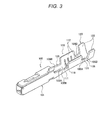
- Fig. 3 is a perspective view showing a configuration of a conventional press bond terminal described in, for example, Patent Reference 1.
- This press bond terminal 100 includes an electrical connection part 101 connected to a terminal of the other connector side (not shown) in the front of a longitudinal direction (also a longitudinal direction of a conductor of an electric wire connected) of the terminal, and includes a conductor press bond part 110 crimped to the conductor in which the distal end of the electric wire (not shown) is exposed in the back of the electrical connection part 101, and further includes a coating crimp part 120 crimped to the portion having an insulating coating in the electric wire in the back of the conductor press bond part 110.
- a first joining part 105 for joining the electrical connection part 101 to the conductor press bond part 110 is included between the electrical connection part 101 and the conductor press bond part 110
- a second joining part 106 for joining the conductor press bond part 110 to the coating crimp part 120 is included between the conductor press bond part 110 and the coating crimp part 120.
- the conductor press bond part 110 is formed in substantially a U-shaped cross section by a base plate 111 and a pair of conductor crimp pieces 112, 112 which is extended upward from both right and left lateral edges of the base plate 111 and is crimped so as to wrap the conductor of the electric wire disposed on an inner surface of the base plate 111.
- the coating crimp part 120 is formed in substantially a U-shaped cross section by a base plate 121 and a pair of coating crimp pieces 122, 122 which is extended upward from both right and left lateral edges of the base plate 121 and is crimped so as to wrap the electric wire (that is, the portion having the insulating coating) disposed on an inner surface of the base plate 121.
- both of the first joining part 105 and the second joining part 106 in the front and back of the conductor press bond part 110 are formed in substantially U-shaped cross sections by base plates 105A, 106A and low side plates 105B, 106B upward erected from both right and left lateral edges of the base plates 105A, 106A.
- the portion ranging from a base plate (not shown) of the front electrical connection part 101 to the base plate of the backmost coating crimp part 120 (that is, the base plate 105A of the first joining part 105, the base plate 111 of the conductor press bond part 110, the base plate 106A of the second joining part 106 and the base plate 121 of the coating crimp part 120) is formed continuously in a shape of one band plate.
- the front and back ends of the low side plate 105B of the first joining part 105 respectively continue with the back end of a side plate (numeral is omitted) of the electrical connection part 101 and each lower half part of the front end of the conductor crimp piece 112 of the conductor press bond part 110
- the front and back ends of the low side plate 106B of the second joining part 106 respectively continue with the back end of the conductor crimp piece 112 of the conductor press bond part 110 and each lower half part of the front end of the coating crimp piece 122 of the coating crimp part 120.
- an inner surface of the conductor press bond part 110 is provided with plural serrations 118 with a recessed groove shape extending in a direction orthogonal to the longitudinal direction (that is, the longitudinal direction of the terminal) of the conductor of the electric wire.
- the press bond terminal 100 is placed on a placement surface (that is, an upper surface) of a lower mold (that is, an anvil) (not shown) and also, the conductor of the distal end of the electric wire is inserted between the conductor crimp pieces 112 of the conductor press bond part 110 and is placed on an upper surface of the base plate 111. Then, by downward moving an upper mold (that is, a crimper) relatively with respect to the lower mold, the distal end sides of the conductor crimp pieces 112 are gradually laid inward by a guide inclined surface of the upper mold.
- a placement surface that is, an upper surface
- a lower mold that is, an anvil
- the distal ends of the conductor crimp pieces 112 are rounded so as to be folded back to the conductor side by a curved surface ranging from the guide inclined surface of the upper mold to a chevron-shaped part of the center, and the distal ends of the conductor crimp pieces 112 are mutually bitten into the conductor while being rubbed together and thereby, the conductor crimp pieces 112 are crimped so as to wrap the conductor.
- the conductor press bond part 110 of the press bond terminal 100 can be connected to the conductor of the electric wire by press bonding.
- the coating crimp part 120 using the lower mold and the upper mold, the coating crimp pieces 122 are gradually bent inward and are crimped to the portion having the insulating coating in the electric wire. This allows the press bond terminal 100 to be electrically and mechanically connected to the electric wire.
- an object of the invention is to provide a press bond terminal capable of easily ensuring compatibility between electrical connection performance and mechanical connection performance in the case of connecting a terminal to an electric wire by reducing a springback of a conductor crimp piece.
- any place ranging from the inner surface of the conductor crimp piece of the conductor press bond part to the inner surface of the side plate of the joining part is provided with the projection, so that a rib effect by the projection or work hardening by forming the projection can increase rigidity of a place of the formed projection and its periphery. Therefore, when the inner surface of the conductor crimp piece is provided with the projection, an increase in rigidity of the conductor crimp piece by the presence itself of the projection can reduce a springback after press bonding of the conductor crimp pieces.
- the region of making close contact with the conductor of the electric wire at the time of press bonding in the inner surface of the conductor crimp piece is provided with the plural projections spaced in the front and back directions as shown in the press bond terminal of (2) described above, the presence of the projections projecting to the side of the conductor of the electric wire in the conductor press bond part can increase internal stress of the conductor press bond part as compared with a press bond part with the same crimp height (C/H) having no projections.
- C/H crimp height
- Figs. 1(a) to 1(c) are configuration views of a press bond terminal of a first embodiment
- Fig. 1(a) is a developed plan view of the press bond terminal
- Fig. 1(b) is a sectional view taken on arrow line A-A of Fig. 1(a)
- Fig. 1(c) is a transverse sectional view showing a state after a conductor press bond part of the press bond terminal is pressed and bonded.
- This press bond terminal 10 includes an electrical connection part 11 connected to a terminal of the other connector side in the front of a longitudinal direction (also a longitudinal direction of a conductor of an electric wire connected) of the terminal, and includes a conductor press bond part 13 crimped to the conductor in which the distal end of the electric wire (not shown) is exposed in the back of the electrical connection part 11, and further includes a coating crimp part 15 crimped to the portion having an insulating coating in the electric wire in the back of the conductor press bond part 13.
- a first joining part 12 for joining the electrical connection part 11 to the conductor press bond part 13 is included between the electrical connection part 11 and the conductor press bond part 13
- a second joining part 14 for joining the conductor press bond part 13 to the coating crimp part 15 is included between the conductor press bond part 13 and the coating crimp part 15.
- the conductor press bond part 13 is formed in substantially a U-shaped cross section by a base plate 13A and a pair of conductor crimp pieces 13B, 13B which is extended upward from both right and left lateral edges of the base plate 13A and is crimped so as to wrap the conductor of the electric wire disposed on an inner surface of the base plate 13A.
- the coating crimp part 15 is formed in substantially a U-shaped cross section by a base plate 15A and a pair of coating crimp pieces 15B, 15B which is extended upward from both right and left lateral edges of the base plate 15A and is crimped so as to wrap the electric wire (the portion having the insulating coating) disposed on an inner surface of the base plate 15A.
- both of the first joining part 12 and the second joining part 14 in the front and back of the conductor press bond part 13 are formed in substantially U-shaped cross sections by base plates 12A, 14A and low side plates 12B, 14B upward erected from both right and left lateral edges of the base plates 12A, 14A.
- the base plates ranging from the front electrical connection part 11 to the backmost coating crimp part 15, that is, a base plate 11A of the electrical connection part 11, the base plate 12A of the first joining part 12, the base plate 13A of the conductor press bond part 13, the base plate 14A of the second joining part 14 and the base plate 15A of the coating crimp part 15 are formed continuously in a shape of one band plate.
- the front and back ends of the low side plate 12B of the first joining part 12 respectively continue with the back end of a side plate 11B of the electrical connection part 11 and each lower half part of the front end of the conductor crimp piece 13B of the conductor press bond part 13, and the front and back ends of the low side plate 14B of the second joining part 14 respectively continue with the back end of the conductor crimp piece 13B of the conductor press bond part 13 and each lower half part of the front end of the coating crimp piece 15B of the coating crimp part 15.
- an inner surface of the conductor press bond part 13 is provided with plural serrations 21 with a recessed groove shape extending in a direction orthogonal to the longitudinal direction (the longitudinal direction of the terminal) of the conductor of the electric wire.
- inner surfaces of a pair of conductor crimp pieces 13B, 13B of the conductor press bond part 13 are provided with plural projections 22 formed by being pushed from an outer surface.
- plural projections spaced in the front and back directions are formed in a region of making close contact with a conductor Wa of an electric wire at the time of press bonding in the inner surfaces of the conductor crimp pieces 13B.
- the press bond terminal 10 is placed on a placement surface (an upper surface) of a lower mold (an anvil) (not shown) and also, the conductor of the distal end of the electric wire is inserted between a pair of conductor crimp pieces 13B, 13B of the conductor press bond part 13 and is placed on an upper surface of the base plate 13A. Then, by downward moving an upper mold (a crimper) relatively with respect to the lower mold, the distal end sides of the conductor crimp pieces 13B are gradually laid inward by a guide inclined surface of the upper mold.
- an upper mold a crimper
- the distal ends of the conductor crimp pieces 13B are rounded so as to be folded back to the side of the conductor Wa by a curved surface ranging from the guide inclined surface of the upper mold to a chevron-shaped part of the center, and the distal ends of the conductor crimp pieces 13B are mutually bitten into the conductor Wa while being rubbed together and thereby, the conductor crimp pieces 13B are crimped so as to wrap the conductor Wa.
- the conductor press bond part 13 of the press bond terminal 10 can be connected to the conductor Wa of the electric wire by press bonding.
- the coating crimp part 15B are gradually bent inward and are crimped to the portion having the insulating coating in the electric wire. This allows the press bond terminal 10 to be electrically and mechanically connected to the electric wire.
- the press bond terminal 10 of the embodiment can have the following effects in a state of making connection by press bonding thus.
- the inner surfaces of the conductor crimp pieces 13B of the conductor press bond part 13 are provided with the projections 22, so that a rib effect by the projections 22 or work hardening by forming the projections 22 can increase rigidity of a place of the formed projections 22 and its periphery (mainly, the conductor crimp pieces 13B).
- a springback after press bonding of the conductor crimp pieces 13B can be reduced, with the result that a press bond shape of the conductor press bond part 13 can surely be maintained and a grip force of the conductor press bond part 13 on the conductor of the electric wire can be improved and also, misalignment between core wires of the conductor Wa can be reduced and the range of compatibility between stable electrical contact and fastening strength can be expanded.
- the presence of the projections 22 projecting to the side of the conductor Wa of the electric wire in the conductor press bond part 13 can increase internal stress of the conductor press bond part 13 as compared with a press bond part with the same crimp height (C/H) having no projections 22.
- C/H crimp height
- an increase in a binding force of the conductor Wa in a region sandwiched between the front and back projections 22 strengthens action of reducing misalignment (particularly, misalignment in the front and back directions) between core wires of the conductor Wa, and a more stable electrical contact state can be maintained.
- Figs. 2(a) to 2(d) are configuration views of a press bond terminal of a second embodiment
- Fig. 2(a) is a developed plan view of the press bond terminal
- Fig. 2(b) is a sectional view taken on arrow line B-B of Fig. 2(a)
- Fig. 2(c) is a partially perspective view showing a state after the conductor press bond part of the press bond terminal is pressed and bonded
- Fig. 2(d) is a sectional view taken on arrow line C-C of Fig. 2(c) .
- This press bond terminal 40 of the second embodiment differs from the press bond terminal 10 of the first embodiment in that an inner surface of a conductor crimp piece 13B of a conductor press bond part 13 is not provided with a projection and an inner surface of a side plate 12B of a first joining part 12 and an inner surface of a side plate 14B of a second joining part 14 are provided with projections 42. Since the others are similar to the first embodiment, explanation is omitted by assigning the same numerals to the same portions.
- the projections can be formed in any place in the range from the inner surfaces of the conductor crimp pieces 13B to the inner surfaces of the side plates 12B, 14B of the joining parts 12, 14.
Landscapes
- Connections Effected By Soldering, Adhesion, Or Permanent Deformation (AREA)
- Multi-Conductor Connections (AREA)
Abstract
Description
- The present invention relates to a press bond terminal of an open barrel type having a conductor press bond part with substantially a U-shaped cross section used in, for example, an electrical equipment system of an automobile.
-
Fig. 3 is a perspective view showing a configuration of a conventional press bond terminal described in, for example, Patent Reference 1. - This
press bond terminal 100 includes anelectrical connection part 101 connected to a terminal of the other connector side (not shown) in the front of a longitudinal direction (also a longitudinal direction of a conductor of an electric wire connected) of the terminal, and includes a conductorpress bond part 110 crimped to the conductor in which the distal end of the electric wire (not shown) is exposed in the back of theelectrical connection part 101, and further includes acoating crimp part 120 crimped to the portion having an insulating coating in the electric wire in the back of the conductorpress bond part 110. Also, a first joiningpart 105 for joining theelectrical connection part 101 to the conductorpress bond part 110 is included between theelectrical connection part 101 and the conductorpress bond part 110, and a second joiningpart 106 for joining the conductorpress bond part 110 to thecoating crimp part 120 is included between the conductorpress bond part 110 and thecoating crimp part 120. - The conductor
press bond part 110 is formed in substantially a U-shaped cross section by abase plate 111 and a pair ofconductor crimp pieces base plate 111 and is crimped so as to wrap the conductor of the electric wire disposed on an inner surface of thebase plate 111. Also, thecoating crimp part 120 is formed in substantially a U-shaped cross section by abase plate 121 and a pair ofcoating crimp pieces base plate 121 and is crimped so as to wrap the electric wire (that is, the portion having the insulating coating) disposed on an inner surface of thebase plate 121. - Also, both of the first joining
part 105 and the second joiningpart 106 in the front and back of the conductorpress bond part 110 are formed in substantially U-shaped cross sections bybase plates low side plates base plates - Then, the portion ranging from a base plate (not shown) of the front
electrical connection part 101 to the base plate of the backmost coating crimp part 120 (that is, thebase plate 105A of the first joiningpart 105, thebase plate 111 of the conductorpress bond part 110, thebase plate 106A of the second joiningpart 106 and thebase plate 121 of the coating crimp part 120) is formed continuously in a shape of one band plate. Also, the front and back ends of thelow side plate 105B of the first joiningpart 105 respectively continue with the back end of a side plate (numeral is omitted) of theelectrical connection part 101 and each lower half part of the front end of theconductor crimp piece 112 of the conductorpress bond part 110, and the front and back ends of thelow side plate 106B of the second joiningpart 106 respectively continue with the back end of theconductor crimp piece 112 of the conductorpress bond part 110 and each lower half part of the front end of thecoating crimp piece 122 of thecoating crimp part 120. - Also, an inner surface of the conductor
press bond part 110 is provided withplural serrations 118 with a recessed groove shape extending in a direction orthogonal to the longitudinal direction (that is, the longitudinal direction of the terminal) of the conductor of the electric wire. - In the case of pressing and bonding the conductor
press bond part 110 of thispress bond terminal 100 to the conductor of the distal end of the electric wire, thepress bond terminal 100 is placed on a placement surface (that is, an upper surface) of a lower mold (that is, an anvil) (not shown) and also, the conductor of the distal end of the electric wire is inserted between theconductor crimp pieces 112 of the conductorpress bond part 110 and is placed on an upper surface of thebase plate 111. Then, by downward moving an upper mold (that is, a crimper) relatively with respect to the lower mold, the distal end sides of theconductor crimp pieces 112 are gradually laid inward by a guide inclined surface of the upper mold. - Then, by further downward moving the upper mold (the crimper) relatively with respect to the lower mold, finally, the distal ends of the
conductor crimp pieces 112 are rounded so as to be folded back to the conductor side by a curved surface ranging from the guide inclined surface of the upper mold to a chevron-shaped part of the center, and the distal ends of theconductor crimp pieces 112 are mutually bitten into the conductor while being rubbed together and thereby, theconductor crimp pieces 112 are crimped so as to wrap the conductor. - By the above operation, the conductor
press bond part 110 of thepress bond terminal 100 can be connected to the conductor of the electric wire by press bonding. In addition, similarly in thecoating crimp part 120, using the lower mold and the upper mold, thecoating crimp pieces 122 are gradually bent inward and are crimped to the portion having the insulating coating in the electric wire. This allows thepress bond terminal 100 to be electrically and mechanically connected to the electric wire. -
- Patent Reference 1:
JP-A-2006-228759 Fig. 1 ) - Incidentally, in the case of the conventional press bond terminal described above, a springback occurs due to a repulsive force of the conductor crimp pieces or the electric wire after press bonding, and the conductor crimp pieces crimped become open slightly and performance of electrical connection between the electric wire and the terminal may decrease. On the other hand, when the conductor crimp pieces are strongly crimped in order to prevent the springback, excessive press bonding may damage a core wire (that is, a conductor) to decrease the strength of fastening between the electric wire and the terminal in turn. Therefore, it is difficult to ensure compatibility between electrical connection performance and mechanical connection performance in the case of connecting the terminal to the electric wire.
- In view of the circumstances described above, an object of the invention is to provide a press bond terminal capable of easily ensuring compatibility between electrical connection performance and mechanical connection performance in the case of connecting a terminal to an electric wire by reducing a springback of a conductor crimp piece.
-
- (1) In order to solve the problem described above, one aspect of the invention provides a press bond terminal in which the front of a longitudinal direction of a terminal is provided with an electrical connection part and the back of the electrical connection part is provided with a conductor press bond part connected by being pressed and bonded to a conductor of a distal end of an electric wire through a first joining part and the back of the conductor press bond part is further provided with a coating crimp part through a second joining part, and the conductor press bond part is formed in substantially a U-shaped cross section by a base plate and a pair of conductor crimp pieces which is extended upward from both right and left lateral edges of the base plate and is crimped so as to wrap the conductor disposed on an inner surface of the base plate, and both of the first joining part and the second joining part are formed in substantially U-shaped cross sections by base plates and low side plates upward erected from both right and left lateral edges of the base plates, and the base plate of the conductor press bond part is formed continuously with the base plates of the first and second joining parts and lower half parts of the conductor crimp pieces of the conductor press bond part are formed continuously with the low side plates of the first and second joining parts, wherein any place ranging from an inner surface of the conductor crimp piece to an inner surface of the side plate of the joining part is provided with a projection.
-
- (2) In the press bond terminal of (1) described above, a region of making close contact with a conductor of an electric wire at the time of press bonding in the inner surface of the conductor crimp piece is preferably provided with the plural projections spaced in front and back directions.
-
- (3) In the press bond terminal of (1) described above, the inner surfaces of each of the side plates of the first joining part and the second joining part are preferably respectively provided with the projections.
- According to the press bond terminal of (1) described above, any place ranging from the inner surface of the conductor crimp piece of the conductor press bond part to the inner surface of the side plate of the joining part is provided with the projection, so that a rib effect by the projection or work hardening by forming the projection can increase rigidity of a place of the formed projection and its periphery. Therefore, when the inner surface of the conductor crimp piece is provided with the projection, an increase in rigidity of the conductor crimp piece by the presence itself of the projection can reduce a springback after press bonding of the conductor crimp pieces. Also, when the inner surface of the side plate of the joining part is provided with the projection even though the inner surface of the conductor crimp piece is not provided with the projection, an increase in rigidity of the side plate of the joining part continuous with the conductor crimp piece can reduce the springback after press bonding of the conductor crimp pieces. As a result, a press bond shape of the conductor press bond part can surely be maintained and also a grip force of the conductor press bond part on the conductor of the electric wire can be improved and thereby, misalignment between core wires of the conductor can be reduced and the range of compatibility between stable electrical contact and fastening strength can be expanded.
- When the region of making close contact with the conductor of the electric wire at the time of press bonding in the inner surface of the conductor crimp piece is provided with the plural projections spaced in the front and back directions as shown in the press bond terminal of (2) described above, the presence of the projections projecting to the side of the conductor of the electric wire in the conductor press bond part can increase internal stress of the conductor press bond part as compared with a press bond part with the same crimp height (C/H) having no projections. Also, in conjunction with an increase in the internal stress, an increase in a binding force of the conductor in a region sandwiched between the front and back projections strengthens action of reducing misalignment between core wires of the conductor, and a more stable electrical contact state can be maintained.
- When the inner surfaces of each of the side plates of the first joining part and the second joining part are respectively provided with the projections as shown in the press bond terminal of (3) described above, the presence of the projections in the inner surfaces of the side plates of the joining parts increases rigidity of the joining parts and accordingly, a springback of the conductor crimp pieces is reduced. This can substantially increase rigidity of the conductor crimp pieces even though the conductor crimp pieces have no projection, and a more stable electrical contact state can be maintained.
-
- [
Fig. 1] Figs. 1(a) to 1(c) are configuration views of a press bond terminal of a first embodiment of the invention, andFig. 1(a) is a developed plan view of the press bond terminal, andFig. 1(b) is a sectional view taken on arrow line A-A ofFig. 1(a), and Fig. 1(c) is a transverse sectional view showing a state after a conductor press bond part of the press bond terminal is pressed and bonded. - [
Fig. 2] Figs. 2(a) to 2(d) are configuration views of a press bond terminal of a second embodiment of the invention, andFig. 2(a) is a developed plan view of the press bond terminal, andFig. 2(b) is a sectional view taken on arrow line B-B ofFig. 2(a), and Fig. 2(c) is a partially perspective view showing a state after the conductor press bond part of the press bond terminal is pressed and bonded, andFig. 2(d) is a sectional view taken on arrow line C-C ofFig. 2(c) . - [
Fig. 3] Fig. 3 is a perspective view showing a configuration of a conventional press bond terminal. - Embodiments of the invention will hereinafter be described using the drawings.
In addition, in a press bond terminal of the invention, the side connected to the other connector is set at the front and the side connected to an electric wire is set at the back. -
Figs. 1(a) to 1(c) are configuration views of a press bond terminal of a first embodiment, andFig. 1(a) is a developed plan view of the press bond terminal, andFig. 1(b) is a sectional view taken on arrow line A-A ofFig. 1(a), and Fig. 1(c) is a transverse sectional view showing a state after a conductor press bond part of the press bond terminal is pressed and bonded. - This
press bond terminal 10 includes anelectrical connection part 11 connected to a terminal of the other connector side in the front of a longitudinal direction (also a longitudinal direction of a conductor of an electric wire connected) of the terminal, and includes a conductorpress bond part 13 crimped to the conductor in which the distal end of the electric wire (not shown) is exposed in the back of theelectrical connection part 11, and further includes acoating crimp part 15 crimped to the portion having an insulating coating in the electric wire in the back of the conductorpress bond part 13. Also, a first joiningpart 12 for joining theelectrical connection part 11 to the conductorpress bond part 13 is included between theelectrical connection part 11 and the conductorpress bond part 13, and a second joiningpart 14 for joining the conductorpress bond part 13 to thecoating crimp part 15 is included between the conductorpress bond part 13 and thecoating crimp part 15. - The conductor
press bond part 13 is formed in substantially a U-shaped cross section by abase plate 13A and a pair ofconductor crimp pieces base plate 13A and is crimped so as to wrap the conductor of the electric wire disposed on an inner surface of thebase plate 13A. - Also, the
coating crimp part 15 is formed in substantially a U-shaped cross section by abase plate 15A and a pair ofcoating crimp pieces base plate 15A and is crimped so as to wrap the electric wire (the portion having the insulating coating) disposed on an inner surface of thebase plate 15A. - Also, both of the first joining
part 12 and the second joiningpart 14 in the front and back of the conductorpress bond part 13 are formed in substantially U-shaped cross sections bybase plates low side plates base plates - Then, the base plates ranging from the front
electrical connection part 11 to the backmostcoating crimp part 15, that is, abase plate 11A of theelectrical connection part 11, thebase plate 12A of the first joiningpart 12, thebase plate 13A of the conductorpress bond part 13, thebase plate 14A of the second joiningpart 14 and thebase plate 15A of thecoating crimp part 15 are formed continuously in a shape of one band plate. Also, the front and back ends of thelow side plate 12B of the first joiningpart 12 respectively continue with the back end of aside plate 11B of theelectrical connection part 11 and each lower half part of the front end of theconductor crimp piece 13B of the conductorpress bond part 13, and the front and back ends of thelow side plate 14B of the second joiningpart 14 respectively continue with the back end of theconductor crimp piece 13B of the conductorpress bond part 13 and each lower half part of the front end of thecoating crimp piece 15B of thecoating crimp part 15. - Also, an inner surface of the conductor
press bond part 13 is provided withplural serrations 21 with a recessed groove shape extending in a direction orthogonal to the longitudinal direction (the longitudinal direction of the terminal) of the conductor of the electric wire. - Also, in this
press bond terminal 10, inner surfaces of a pair ofconductor crimp pieces press bond part 13 are provided withplural projections 22 formed by being pushed from an outer surface. In theseprojections 22, plural projections spaced in the front and back directions are formed in a region of making close contact with a conductor Wa of an electric wire at the time of press bonding in the inner surfaces of theconductor crimp pieces 13B. - In the case of pressing and bonding the conductor
press bond part 13 of thispress bond terminal 10 to the conductor Wa of the distal end of the electric wire, thepress bond terminal 10 is placed on a placement surface (an upper surface) of a lower mold (an anvil) (not shown) and also, the conductor of the distal end of the electric wire is inserted between a pair ofconductor crimp pieces press bond part 13 and is placed on an upper surface of thebase plate 13A. Then, by downward moving an upper mold (a crimper) relatively with respect to the lower mold, the distal end sides of theconductor crimp pieces 13B are gradually laid inward by a guide inclined surface of the upper mold. Then, by further downward moving the upper mold (the crimper) relatively with respect to the lower mold, finally, as shown inFig. 1(c) , the distal ends of theconductor crimp pieces 13B are rounded so as to be folded back to the side of the conductor Wa by a curved surface ranging from the guide inclined surface of the upper mold to a chevron-shaped part of the center, and the distal ends of theconductor crimp pieces 13B are mutually bitten into the conductor Wa while being rubbed together and thereby, theconductor crimp pieces 13B are crimped so as to wrap the conductor Wa. By the above operation, the conductorpress bond part 13 of thepress bond terminal 10 can be connected to the conductor Wa of the electric wire by press bonding. Similarly in thecoating crimp part 15, using the lower mold and the upper mold, thecoating crimp pieces 15B are gradually bent inward and are crimped to the portion having the insulating coating in the electric wire. This allows thepress bond terminal 10 to be electrically and mechanically connected to the electric wire. - The
press bond terminal 10 of the embodiment can have the following effects in a state of making connection by press bonding thus. - First, the inner surfaces of the
conductor crimp pieces 13B of the conductorpress bond part 13 are provided with theprojections 22, so that a rib effect by theprojections 22 or work hardening by forming theprojections 22 can increase rigidity of a place of the formedprojections 22 and its periphery (mainly, theconductor crimp pieces 13B). Therefore, a springback after press bonding of theconductor crimp pieces 13B can be reduced, with the result that a press bond shape of the conductorpress bond part 13 can surely be maintained and a grip force of the conductorpress bond part 13 on the conductor of the electric wire can be improved and also, misalignment between core wires of the conductor Wa can be reduced and the range of compatibility between stable electrical contact and fastening strength can be expanded. - Also, the presence of the
projections 22 projecting to the side of the conductor Wa of the electric wire in the conductorpress bond part 13 can increase internal stress of the conductorpress bond part 13 as compared with a press bond part with the same crimp height (C/H) having noprojections 22. Also, in conjunction with an increase in the internal stress, an increase in a binding force of the conductor Wa in a region sandwiched between the front andback projections 22 strengthens action of reducing misalignment (particularly, misalignment in the front and back directions) between core wires of the conductor Wa, and a more stable electrical contact state can be maintained. -
Figs. 2(a) to 2(d) are configuration views of a press bond terminal of a second embodiment, andFig. 2(a) is a developed plan view of the press bond terminal, andFig. 2(b) is a sectional view taken on arrow line B-B ofFig. 2(a), and Fig. 2(c) is a partially perspective view showing a state after the conductor press bond part of the press bond terminal is pressed and bonded, andFig. 2(d) is a sectional view taken on arrow line C-C ofFig. 2(c) . - This
press bond terminal 40 of the second embodiment differs from thepress bond terminal 10 of the first embodiment in that an inner surface of aconductor crimp piece 13B of a conductorpress bond part 13 is not provided with a projection and an inner surface of aside plate 12B of a first joiningpart 12 and an inner surface of aside plate 14B of a second joiningpart 14 are provided withprojections 42. Since the others are similar to the first embodiment, explanation is omitted by assigning the same numerals to the same portions. - By providing the inner surfaces of the
side plates parts projections 42 thus, rigidity of theside plates parts conductor crimp pieces 13B is reduced. This can substantially increase rigidity of theconductor crimp pieces 13B even though theconductor crimp pieces 13B have no projection. As a result, a press bond shape of the conductorpress bond part 13 can surely be maintained and a grip force of the conductorpress bond part 13 on a conductor of an electric wire can be improved and also, misalignment between core wires of the conductor can be reduced and the range of compatibility between stable electrical contact and fastening strength can be expanded. - In addition, the projections can be formed in any place in the range from the inner surfaces of the
conductor crimp pieces 13B to the inner surfaces of theside plates parts - The present application is based on Japanese patent application (patent application No. 2009-247863) filed on October 28, 2009, and the contents of the patent application are hereby incorporated by reference.
-
- 10, 40
- PRESS BOND TERMINAL
- 11
- ELECTRICAL CONNECTION PART
- 12
- FIRST JOINING PART
- 12A
- BASE PLATE
- 12B
- SIDE PLATE
- 13
- CONDUCTOR PRESS BOND PART
- 13A
- BASE PLATE
- 13B
- CONDUCTOR CRIMP PIECE
- 14
- SECOND JOINING PART
- 14A
- BASE PLATE
- 14B
- SIDE PLATE
- 15
- COATING CRIMP PART
- 22
- PROJECTION
- 42
- PROJECTION
Claims (3)
- A press bond terminal in which the front of a longitudinal direction of a terminal is provided with an electrical connection part and the back of the electrical connection part is provided with a conductor press bond part connected by being pressed and bonded to a conductor of a distal end of an electric wire through a first joining part and the back of the conductor press bond part is further provided with a coating crimp part through a second joining part, and the conductor press bond part is formed in substantially a U-shaped cross section by a base plate and a pair of conductor crimp pieces which is extended upward from both right and left lateral edges of the base plate and is crimped so as to wrap the conductor disposed on an inner surface of the base plate, and both of the first joining part and the second joining part are formed in substantially U-shaped cross sections by base plates and low side plates upward erected from both right and left lateral edges of the base plates, and the base plate of the conductor press bond part is formed continuously with the base plates of the first and second joining parts and lower half parts of the conductor crimp pieces of the conductor press bond part are formed continuously with the low side plates of the first and second joining parts, wherein any place ranging from an inner surface of the conductor crimp piece to an inner surface of the side plate of the joining part is provided with a projection.
- The press bond terminal according to claim 1, wherein a region of making close contact with a conductor of an electric wire at the time of press bonding in the inner surface of the conductor crimp piece is preferably provided with the plural projections spaced in front and back directions.
- The press bond terminal according to claim 1, wherein the inner surfaces of each of the side plates of the first joining part and the second joining part are preferably respectively provided with the projections.
Applications Claiming Priority (2)
| Application Number | Priority Date | Filing Date | Title |
|---|---|---|---|
| JP2009247863A JP2011096451A (en) | 2009-10-28 | 2009-10-28 | Crimping terminal |
| PCT/JP2010/068881 WO2011052548A1 (en) | 2009-10-28 | 2010-10-25 | Crimp terminal |
Publications (2)
| Publication Number | Publication Date |
|---|---|
| EP2495813A1 true EP2495813A1 (en) | 2012-09-05 |
| EP2495813A4 EP2495813A4 (en) | 2013-03-27 |
Family
ID=43921971
Family Applications (1)
| Application Number | Title | Priority Date | Filing Date |
|---|---|---|---|
| EP10826680A Withdrawn EP2495813A4 (en) | 2009-10-28 | 2010-10-25 | CRIMPING TERMINAL |
Country Status (5)
| Country | Link |
|---|---|
| US (1) | US9054431B2 (en) |
| EP (1) | EP2495813A4 (en) |
| JP (1) | JP2011096451A (en) |
| CN (1) | CN102598414A (en) |
| WO (1) | WO2011052548A1 (en) |
Cited By (1)
| Publication number | Priority date | Publication date | Assignee | Title |
|---|---|---|---|---|
| EP4354663A1 (en) * | 2022-10-13 | 2024-04-17 | Wolf Neumann-Henneberg | Crimp connector for mechanical and electrically conductive connection of an electrical connection contact to an electrical conductor and crimped connection of an electrical connection contact with an electrical conductor |
Families Citing this family (18)
| Publication number | Priority date | Publication date | Assignee | Title |
|---|---|---|---|---|
| JP2011096452A (en) * | 2009-10-28 | 2011-05-12 | Yazaki Corp | Crimping terminal |
| JP2013149564A (en) * | 2012-01-23 | 2013-08-01 | Auto Network Gijutsu Kenkyusho:Kk | Terminal fitting |
| JP5992231B2 (en) * | 2012-07-02 | 2016-09-14 | 矢崎総業株式会社 | Crimp structure of wire and terminal |
| WO2014129220A1 (en) * | 2013-02-19 | 2014-08-28 | 古河電気工業株式会社 | Electric wire connection structure, method for manufacturing said electric wire connection structure, connector provided with said electric wire connection structure, and crimping die |
| JP2014179260A (en) * | 2013-03-15 | 2014-09-25 | Sumitomo Wiring Syst Ltd | Corrosion-proof terminal, wire with corrosion-proof terminal and method of manufacturing wire with corrosion-proof terminal |
| JP6454062B2 (en) | 2013-03-21 | 2019-01-16 | 矢崎総業株式会社 | Crimp terminal |
| US10230178B2 (en) | 2013-06-07 | 2019-03-12 | Amphenol Fci Asia Pte Ltd | Cable connector |
| US9972932B2 (en) * | 2013-08-19 | 2018-05-15 | Fci Americas Technology Llc | Electrical connector with high retention force |
| CN105594062B (en) | 2013-11-01 | 2018-03-20 | 古河电气工业株式会社 | Wire harness, the connection method of terminal and coated wire, mould |
| JP6749039B2 (en) | 2013-11-13 | 2020-09-02 | 矢崎総業株式会社 | Wire with terminal |
| CN110994242B (en) | 2013-12-03 | 2022-03-11 | 安费诺富加宜(亚洲)私人有限公司 | Connector and pin receiving contact for such a connector |
| JP6020436B2 (en) * | 2013-12-16 | 2016-11-02 | 住友電装株式会社 | Terminal for connecting electric wire and electric wire connecting structure of the terminal |
| JP2018037374A (en) * | 2016-09-02 | 2018-03-08 | 矢崎総業株式会社 | Electric wire with terminal |
| JP6904147B2 (en) * | 2017-08-01 | 2021-07-14 | 株式会社オートネットワーク技術研究所 | Wire with terminal |
| CN107959164A (en) * | 2017-11-19 | 2018-04-24 | 中山市丰申电器有限公司 | Machining terminal structure capable of preventing copper wire from being exposed |
| MX2020009647A (en) | 2018-03-16 | 2021-02-26 | Fci Usa Llc | High density electrical connectors. |
| DE202018105269U1 (en) * | 2018-09-14 | 2019-12-17 | Weidmüller Interface GmbH & Co. KG | Busbar for an electrical conductor and assembly with the busbar |
| JP2023006152A (en) * | 2021-06-30 | 2023-01-18 | 株式会社オートネットワーク技術研究所 | Connection terminal and electric wire with connection terminal |
Family Cites Families (23)
| Publication number | Priority date | Publication date | Assignee | Title |
|---|---|---|---|---|
| US3831132A (en) | 1971-04-29 | 1974-08-20 | Molex Inc | Crimp terminal for aluminum wire |
| US3892459A (en) * | 1974-06-21 | 1975-07-01 | Amp Inc | Open barrel terminal and method for terminating an electrical wire therein |
| US4010538A (en) * | 1975-07-01 | 1977-03-08 | Amp Incorporated | Phono plug |
| JPS55120079U (en) * | 1979-02-16 | 1980-08-25 | ||
| JPS55120079A (en) | 1979-03-08 | 1980-09-16 | Suwa Seikosha Kk | Liquid crystal display unit |
| JPH03121661A (en) | 1989-10-04 | 1991-05-23 | Toshiba Corp | Communication terminal equipment |
| JPH0722046Y2 (en) * | 1990-03-27 | 1995-05-17 | 矢崎総業株式会社 | Crimp terminal |
| GB9313652D0 (en) | 1993-07-02 | 1993-08-18 | Amp Gmbh | Electrical terminal with lead strain relief means |
| US5593328A (en) * | 1993-11-04 | 1997-01-14 | Sumitomo Wiring Systems, Ltd. | Female terminal fitting for connector |
| JP2001217013A (en) * | 2000-02-02 | 2001-08-10 | Sumitomo Wiring Syst Ltd | Terminal fitting |
| JP2003157924A (en) | 2001-11-22 | 2003-05-30 | Sumitomo Wiring Syst Ltd | Female side terminal fitting |
| US7249983B2 (en) * | 2005-05-19 | 2007-07-31 | Deutsch Engineered Connecting Devices | Sleeveless stamped and formed socket contact |
| JP2007257905A (en) * | 2006-03-22 | 2007-10-04 | Japan Aviation Electronics Industry Ltd | Terminal and connector using the same |
| JP4078564B2 (en) | 2006-06-02 | 2008-04-23 | 住友電装株式会社 | Female terminal fitting |
| WO2008120632A1 (en) | 2007-03-29 | 2008-10-09 | Autonetworks Technologies, Ltd. | Connector terminal and connector with that connector terminal |
| JP5030232B2 (en) | 2008-01-28 | 2012-09-19 | 矢崎総業株式会社 | Crimp terminal for aluminum wire |
| JP2009247863A (en) | 2008-04-04 | 2009-10-29 | Takaharu Horie | Stand for micromotor |
| JP5400318B2 (en) | 2008-04-15 | 2014-01-29 | 矢崎総業株式会社 | Crimp terminal for aluminum wire |
| EP2151891A1 (en) * | 2008-08-06 | 2010-02-10 | Sumitomo Wiring Systems, Ltd. | A terminal fitting and a method of forming it |
| JP5311962B2 (en) | 2008-10-24 | 2013-10-09 | 矢崎総業株式会社 | Crimp terminal for aluminum wire and method for manufacturing crimp terminal for aluminum wire |
| JP5403788B2 (en) * | 2008-12-12 | 2014-01-29 | 矢崎総業株式会社 | Crimping structure of crimping barrel, crimping terminal and crimping device |
| JP5437685B2 (en) * | 2009-04-07 | 2014-03-12 | 矢崎総業株式会社 | Crimping terminal, crimping structure of crimping terminal, and crimping method of crimping terminal |
| JP2011096452A (en) * | 2009-10-28 | 2011-05-12 | Yazaki Corp | Crimping terminal |
-
2009
- 2009-10-28 JP JP2009247863A patent/JP2011096451A/en active Pending
-
2010
- 2010-10-25 WO PCT/JP2010/068881 patent/WO2011052548A1/en not_active Ceased
- 2010-10-25 US US13/504,292 patent/US9054431B2/en not_active Expired - Fee Related
- 2010-10-25 CN CN2010800488015A patent/CN102598414A/en active Pending
- 2010-10-25 EP EP10826680A patent/EP2495813A4/en not_active Withdrawn
Cited By (1)
| Publication number | Priority date | Publication date | Assignee | Title |
|---|---|---|---|---|
| EP4354663A1 (en) * | 2022-10-13 | 2024-04-17 | Wolf Neumann-Henneberg | Crimp connector for mechanical and electrically conductive connection of an electrical connection contact to an electrical conductor and crimped connection of an electrical connection contact with an electrical conductor |
Also Published As
| Publication number | Publication date |
|---|---|
| CN102598414A (en) | 2012-07-18 |
| JP2011096451A (en) | 2011-05-12 |
| US20120214361A1 (en) | 2012-08-23 |
| WO2011052548A1 (en) | 2011-05-05 |
| EP2495813A4 (en) | 2013-03-27 |
| US9054431B2 (en) | 2015-06-09 |
Similar Documents
| Publication | Publication Date | Title |
|---|---|---|
| EP2495813A1 (en) | Crimp terminal | |
| EP2495814A1 (en) | Crimp terminal | |
| US10003136B2 (en) | Crimp terminal and crimping structure with respect to electrical wire thereof | |
| CN102144336B (en) | terminal adapter | |
| EP2151891A1 (en) | A terminal fitting and a method of forming it | |
| KR20130099233A (en) | Electrical contact having rhombic knurl pattern | |
| WO2009154108A1 (en) | Metal terminal fitting and electric wire with terminal | |
| JP2008277302A (en) | Electric contact | |
| CN105191001A (en) | Crimping terminal | |
| JP2020107615A (en) | Cable assembly | |
| US20200287300A1 (en) | Connection Terminal, Method Of Connecting Wires Using The Same And Pressing Die | |
| JP2009245695A (en) | Crimp terminal | |
| JP2009245701A (en) | Crimp terminal | |
| JP2013196921A (en) | Electric wire with crimp-style terminal, and method of crimping the crimp-style terminal to electric wire | |
| US9048606B2 (en) | Press bond terminal and method for pressing and bonding terminal | |
| WO2015108123A1 (en) | Terminal crimp structure and terminal crimping method | |
| JP2010097781A (en) | Manufacturing method of electric wire with terminal fitting, and terminal crimping device | |
| JP2009181777A (en) | Crimp structure of wire and terminal | |
| KR20160119689A (en) | Coil end connecting structure | |
| JP2011243519A (en) | Crimp terminal and flat cable with crimp terminal | |
| JP2007059304A (en) | Electric wire with terminal and manufacturing method thereof | |
| JP2010244888A (en) | Crimp terminal and crimp structure | |
| JP2011124135A (en) | Flat cable with terminal fitting, and terminal crimping die for flat cable | |
| EP2187478A1 (en) | A terminal fitting, a wire connection structure and a connecting method | |
| JP5195191B2 (en) | Terminal fittings and electric wires with terminal fittings |
Legal Events
| Date | Code | Title | Description |
|---|---|---|---|
| PUAI | Public reference made under article 153(3) epc to a published international application that has entered the european phase |
Free format text: ORIGINAL CODE: 0009012 |
|
| 17P | Request for examination filed |
Effective date: 20120425 |
|
| AK | Designated contracting states |
Kind code of ref document: A1 Designated state(s): AL AT BE BG CH CY CZ DE DK EE ES FI FR GB GR HR HU IE IS IT LI LT LU LV MC MK MT NL NO PL PT RO RS SE SI SK SM TR |
|
| DAX | Request for extension of the european patent (deleted) | ||
| A4 | Supplementary search report drawn up and despatched |
Effective date: 20130221 |
|
| RIC1 | Information provided on ipc code assigned before grant |
Ipc: H01R 4/20 20060101ALI20130215BHEP Ipc: H01R 4/18 20060101AFI20130215BHEP |
|
| STAA | Information on the status of an ep patent application or granted ep patent |
Free format text: STATUS: THE APPLICATION HAS BEEN WITHDRAWN |
|
| 18W | Application withdrawn |
Effective date: 20170922 |