EP2495996A2 - Verfahren zur Bestimmung der maximalen stabilen Verstärkung am Hörgerät - Google Patents
Verfahren zur Bestimmung der maximalen stabilen Verstärkung am Hörgerät Download PDFInfo
- Publication number
- EP2495996A2 EP2495996A2 EP11192966A EP11192966A EP2495996A2 EP 2495996 A2 EP2495996 A2 EP 2495996A2 EP 11192966 A EP11192966 A EP 11192966A EP 11192966 A EP11192966 A EP 11192966A EP 2495996 A2 EP2495996 A2 EP 2495996A2
- Authority
- EP
- European Patent Office
- Prior art keywords
- signal
- hearing aid
- input
- output
- sound
- Prior art date
- Legal status (The legal status is an assumption and is not a legal conclusion. Google has not performed a legal analysis and makes no representation as to the accuracy of the status listed.)
- Granted
Links
Images

Classifications
-
- H—ELECTRICITY
- H04—ELECTRIC COMMUNICATION TECHNIQUE
- H04R—LOUDSPEAKERS, MICROPHONES, GRAMOPHONE PICK-UPS OR LIKE ACOUSTIC ELECTROMECHANICAL TRANSDUCERS; ELECTRIC HEARING AIDS; PUBLIC ADDRESS SYSTEMS
- H04R25/00—Electric hearing aids
- H04R25/70—Adaptation of deaf aid to hearing loss, e.g. initial electronic fitting
-
- H—ELECTRICITY
- H04—ELECTRIC COMMUNICATION TECHNIQUE
- H04R—LOUDSPEAKERS, MICROPHONES, GRAMOPHONE PICK-UPS OR LIKE ACOUSTIC ELECTROMECHANICAL TRANSDUCERS; ELECTRIC HEARING AIDS; PUBLIC ADDRESS SYSTEMS
- H04R25/00—Electric hearing aids
- H04R25/55—Electric hearing aids using an external connection, either wireless or wired
- H04R25/558—Remote control, e.g. of amplification, frequency
-
- H—ELECTRICITY
- H04—ELECTRIC COMMUNICATION TECHNIQUE
- H04R—LOUDSPEAKERS, MICROPHONES, GRAMOPHONE PICK-UPS OR LIKE ACOUSTIC ELECTROMECHANICAL TRANSDUCERS; ELECTRIC HEARING AIDS; PUBLIC ADDRESS SYSTEMS
- H04R2225/00—Details of deaf aids covered by H04R25/00, not provided for in any of its subgroups
- H04R2225/41—Detection or adaptation of hearing aid parameters or programs to listening situation, e.g. pub, forest
-
- H—ELECTRICITY
- H04—ELECTRIC COMMUNICATION TECHNIQUE
- H04R—LOUDSPEAKERS, MICROPHONES, GRAMOPHONE PICK-UPS OR LIKE ACOUSTIC ELECTROMECHANICAL TRANSDUCERS; ELECTRIC HEARING AIDS; PUBLIC ADDRESS SYSTEMS
- H04R25/00—Electric hearing aids
- H04R25/45—Prevention of acoustic reaction, i.e. acoustic oscillatory feedback
- H04R25/453—Prevention of acoustic reaction, i.e. acoustic oscillatory feedback electronically
-
- H—ELECTRICITY
- H04—ELECTRIC COMMUNICATION TECHNIQUE
- H04R—LOUDSPEAKERS, MICROPHONES, GRAMOPHONE PICK-UPS OR LIKE ACOUSTIC ELECTROMECHANICAL TRANSDUCERS; ELECTRIC HEARING AIDS; PUBLIC ADDRESS SYSTEMS
- H04R25/00—Electric hearing aids
- H04R25/50—Customised settings for obtaining desired overall acoustical characteristics
- H04R25/505—Customised settings for obtaining desired overall acoustical characteristics using digital signal processing
Definitions
- the invention may e.g. be useful for the customization of hearing aid parameters in cooperation with fitting software and/or for improving signal to noise ratio of a detected or measured signal.
- the Hearing Instrument itself can carry out all, or part of a measurement procedure.
- Using the Hearing Instrument, rather than an external device, to perform a measurement often brings significant benefits, as in the case of measuring the so-called individual threshold of feedback (also called "Critical Gain").
- the individual threshold of feedback is a measure of the gain limitations that should be taken into account in order to reduce unwanted whistling sounds, and this threshold is unique for every hearing instrument fitting.
- the present invention addresses both of the above potential causes of inaccuracy.
- the general idea is to apply the "matched filter” concept (which is taken from telecommunications engineering) to audio processing in Hearing Instruments (HI), with particular focus on
- a matched filter is capable of identifying a signal of known waveform from noise, even if the signal-to-noise ratio is very poor, cf. e.g. W.L. Melvin, IEEE A&E Systems Magazine, Vol. 19, No. 1, January 2004, page 19-35 or G.L. Turin, IRE Transactions on Information Theory, Vol. 6, No. 3, June 1960, page 311-329 .
- a comparison of analogue and digital implementations of matched filters is e.g.
- An idealized matched filter is a delay-free linear time-invariant system with one input and one output.
- an ideal matched filter When matched to a given waveform s(t), an ideal matched filter has an impulse response that equals s(-t).
- the filter's output is produced by cross-correlating its input signal with a given waveform s(t). That means that for an input of s(t) the filter outputs the auto-correlation function of s(t).
- the filter attenuates all signals with waveforms different from s(t). If s(t) is the filter's input signal then we can measure its level by feeding the output of the matched filter into a level meter. The filter attenuates background noise, improving measurement accuracy.
- An ideal matched filter is a non-causal system and cannot be implemented. However, one can implement a sufficient approximation of the idealized matched filter by introducing a time delay, and if s(t) is periodic, by limiting the length of the signal to correlate with. We can use windowing techniques to generate a fragment of s(t) short enough to be correlated with the input signal of the filter.
- matched filter will denote a feasible implementation that approximates an idealized matched filter.
- An object of the present invention is to improve the signal-to-noise ratio of a signal to be measured or detected in a hearing instrument compared to prior art solutions.
- a hearing aid system :
- a limited time interval is in the range from 0.2 milliseconds to 20 milliseconds, such as 1 millisecond.
- An advantage of the invention is that it provides an alternative scheme for improving signal to noise ratio of a hearing aid.
- the hearing aid system comprises a signal path comprising a signal processing unit for processing the digital input signal - at least for adapting the digital input signal to a user's hearing profile - and for providing a processed output signal.
- the signal path (also termed the forward path) comprises the signal picked up by the input transducer to be processed by the signal processing unit and the components for processing the signal to be presented (e.g. via an output transducer) as an audio signal adapted to a user's needs.
- the hearing aid system comprises a D/A converter for converting a processed output signal to an analogue electrical output signal.
- the electrical input signal is split into a number of frequency bands (e.g. 4 or 8 or 16 or more) that are treated individually.
- the frequency range considered is between 0 and 20 kHz, such as between 10 Hz and 10 kHz.
- frames of digitized values of amplitude versus time are generated for each frequency band (and for a number of discrete frequencies in each band), thereby generating a digital time-frequency matrix.
- the hearing aid system comprises an output transducer, such as a receiver, for converting a digital or analogue electrical output signal to an output sound signal.
- an output transducer such as a receiver
- the hearing aid system comprises a signal generator for generating a predefined source signal s(t).
- the hearing aid system is adapted to provide that the source signal can be added to the output of the signal processing unit, e.g. via a digital SUM-unit, possibly controlled by a switch for enabling or disabling the source signal from the signal generator to the SUM-unit.
- the hearing aid system is adapted to provide that the source signal can be connected directly to the D/A converter or output transducer, e.g. by disabling the input to the SUM-unit from the signal processing unit.
- the hearing aid system can be used to generate a predefined output sound signal which can be used in measurements of specific parameters of the hearing aid in the current 'natural setting' consisting of the actual user's ear a specific acoustical environment.
- the signal generator is adapted to generate a signal with a predefined waveform s(t).
- the matched filter is adapted to have an impulse response of a predefined shape s(-t + ⁇ t) for a certain range of t, where ⁇ t is a certain time delay.
- the matched filter is adapted to provide the auto-correlation function of s(t) as an output.
- This signal can be used in the further processing e.g. to extract information about the acoustic feedback path, to adjust parameters of the signal processing, including to improve feedback cancellation.
- the hearing aid system comprises an alternative path comprising the matched filter.
- the digital input signal from the A/D converter is fed to the matched filter.
- the electrical analogue input signal is split into frequency bands by a filter bank prior to A/D conversion.
- the splitting of the signal into frequency bands is based on the digitized signals (i.e. after A/D-conversion). In both cases, a frequency split signal comprising individual frequency bands is fed to the matched filter (or filters) and processed individually.
- the alternative path further comprises a detection unit for evaluating the signal from the matched filter.
- the output of the matched filter is fed to the detection unit.
- the output of the detection unit is connectable to the signal processing unit for further evaluation.
- the signal processing unit is connectable to the signal generator to allow the signal generator to be controlled from the signal processing unit.
- the output of the detection unit is connectable to the external programming unit via the programming interface.
- the signal generator is connectable to the external programming unit via the programming interface. This has the advantage of allowing fitting software running on the programming unit to monitor and/or control and/or display the generated and detected signals in the hearing aid.
- control unit is adapted to switch the hearing aid system into a low power mode based on pre-defined criteria.
- predefined criteria may include a comparison of current output signals from the detector with stored ones for 'active acoustic environments'.
- a 'low power mode' can e.g. be a mode where power consumption is significantly reduced compared to normal operation, e.g. reduced to less than 20% or less than 10% or less than 5% of the normal consumption. Thereby power can be saved when the hearing aid system is not in use. In an embodiment, power can automatically be switched totally off. A manual on/off option is further provided.
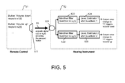
- the hearing instrument is adapted to identify the known waveform of the remote control signal from the sound picked up by its input transducer and react to it by modifying its behaviour, e.g. by changing a parameter setting, e.g. volume.
- the hearing instrument comprises a matched filter in combination with a level detector and a 1-bit quantizer for identifying the remote control signal.
- the signal generator of the remote control is adapted to transmit signals of different waveforms representing different remote control commands.
- the invention provides a method of making a Critical Gain measurement on a hearing aid, the hearing aid comprising an input transducer for converting an input sound signal to an electrical input signal and an output transducer for converting a processed electrical output signal to a processed sound output, the method comprising,
- a method of making a Critical Gain measurement on a hearing aid comprising an input transducer for converting an input sound signal to an electrical input signal and an output transducer for converting a processed electrical output signal to a processed sound output, the method comprising
- the hearing aid comprises a signal path comprising a signal processing unit for adapting the input signal to a user's hearing profile and an alternative path comprising the matched filter. It is intended that other features of a hearing aid as described above under the heading "A hearing aid system” and as described in the section “Mode(s) for carrying out the invention” can be combined with the present method.
- the method comprises communication with a programming unit, e.g. a personal computer, whereon fitting software runs and from which the gain measurement can be controlled.
- a programming unit e.g. a personal computer
- fitting software runs and from which the gain measurement can be controlled.
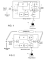
- Fig. 1 shows an embodiment of a hearing aid system according to the invention wherein a signal source (or signal of interest) is located outside the hearing instrument.
- FIG. 1 is a general diagram of an embodiment of a hearing aid system according to the invention.
- the hearing aid system comprises a Hearing Instrument (enclosed by a solid rectangle above the Hearing Instrument reference) comprising a forward path comprising
- an alternative path (to the signal path) is shown taking its input from the A / D -converter (in the form of the digital input signal 12) and comprising a matched filter (MF), matched to the waveform generated by the signal generator (SG), where the output 18 of the matched filter is fed to a detector and post-processing unit (D+PP), whose output 19 (when switch S3 is closed) is connected to a PC interface (PC-I) connectable to a PC comprising Fitting Software and to the signal processing unit (when switch S5 is closed).
- a PC is - via a wired or wireless connection 21 - connected to the hearing aid via the PC Interface of the hearing aid.
- Fitting software located on the PC is used to "fit" the hearing aid to a hearing profile of an end user.
- a (possibly two-way) connection between the Fitting software on the PC via connection 21 to the PC interface (PC-I) in the hearing instrument can be established to the signal generator (SG) via connection 20 (when switch S4 is closed), thereby providing a possibility to control the signal generator from the fitting software and optionally to forward the predefined signal from the signal generator to the Fitting software.
- the signal generator (SG) can be controlled by a control signal 22 from the signal processing unit SP (via switch S6 in a closed condition).
- the switches S1-S6 are symbolic components for electrically (e.g. digitally) connecting (enabling) or disconnecting (disabling) the two sides of the switch.
- the switch functions can by physically implemented in any appropriate way. Some or all of the individual switches can be controlled by the signal processing unit or via the fitting software.
- the detector part of the detector and post-processing unit can e.g. rectify or square its input signal and then feed it into a short-time integrator that applies one of the known numeric integration schemes in order to obtain a level estimate.
- the post-processing unit retrieves the actually desired information from the resulting detector output.
- the post-processing unit could be a comparator whose output is "signal detected", if the detector's output exceeds a certain threshold or it could be a decision unit deciding whether the signal level is sufficient for a reliable measurement.
- the detector (possibly in combination with the signal generator) can be used for measuring the level of or detecting the presence of a signal of known waveform, e.g. while the Hearing Instrument is worn. Including the matched filter in the alternative path improves the signal to noise ratio between the signal of known waveform and Background noise from the environment.
- the improved measurement or detection can be used for different applications or modes of operation, some of which are briefly exemplified in the following:
- the Hl does not operate in a normal way (see also the example below with reference to FIG. 2 ).
- the signal generator (SG) and receiver 17 are used to produce a tone (output sound signal) that will be measured at the input (open loop measurement, which means that the user of the hearing instrument does not hear the input from the microphone).
- the signal processing block (cf. FIG. 2 ) is not used in this case.
- the measurement is controlled by the PC (fitting software) and the results can for example be displayed on the PC screen.
- the embodiment of a hearing aid according to the invention shown in FIG. 2 corresponds to the hearing aid of FIG. 1 with switches S1 open, S2 closed, S3 closed, S4 closed, S5 open and S6 open.
- the HI is worn by the user, and operates normally - adapting incoming sound according to the needs of the user.
- the HI is not necessarily connected to the fitting software.
- the improved measurement (involving the matched filter and the detector and post-processing unit) identifies a special pattern from the background noise by attenuating noise influences in the matched filter and then routing the matched filter's output signal into a level meter that would for example square this signal and do short time integration on the result.
- the information extracted in this way can be used, for example, to adjust the signal processing (cf. FIG. 3 ).
- the embodiment of a hearing aid according to the invention shown in FIG. 3 corresponds to the hearing aid of FIG. 1 with switches S1 closed, S2 closed, S3 open, S4 open, S5 closed and S6 closed.
- the HI is located behind or in the ear of a user (i.e. in normal operation) and is connected to the fitting software on the PC via the PC Interface (cf. e.g. FIG. 1 with switches S2, S4, S5 S6 open and switches S1 and S3 closed).
- the improved measurement identifies a special pattern out of background noise by attenuating noise influences in the matched filter and then routing the matched filter's output signal into a level meter that would for example square this signal and do short time integration on the result.
- the result of the measurement in the level meter does not change the signal processing, but the information is used in the fitting software to demonstrate functionality.
- the fitting software could control sounds coming from the different loudspeakers, conduct measurements of the signal level by means of the Hearing Instrument's "Detector + Post-processing" (D + PP) unit, compute the attenuation applied by the directional microphone and display the results on the PC screen.
- This application suffers from acoustic background noise in the room where the Hearing Instrument wearer and the loudspeakers are located.
- the invention allows using a matched filter for filtering the sound currently coming from one of the loudspeakers out of the background noise. In the given example, this can improve accuracy of level measurements and thus the demonstration of the directional microphone's operation.
- Fig. 2 is an illustration of a critical gain measurement using a hearing aid system according to an embodiment of the invention.
- the components of the hearing instruments shown in FIG. 2 are identical to those shown in FIG. 1 , but their interconnection is different.
- the Detector + Post-processing unit of FIG. 1 is substituted by a Level detector (LD) in FIG. 2 .
- the purpose of the Level detector is to measure level of signal produced by the signal generator that is picked up by the Hearing Instrument's input transducer. Subtracting the level of the signal that was produced by the signal generator from the measurement result on the dB scale yields an estimate of the transfer function between signal generator and Level detector at the frequency or frequency range of the signal emitted by the signal generator.
- the Level detector can be implemented as follows: its input signal is rectified or squared and then passed to a short-time integrator that applies one of the known numeric integration schemes in order to obtain a level estimate.
- the processed output from the Signal Processing unit (SP) is not coupled to the D / A -converter.
- the signal generator here a Sine Generator
- the Fitting Software of the PC is controlled by the Fitting Software of the PC, which is coupled to the Hearing Instrument via the PC Interface.
- the coupling between PC and Hearing Instrument can be a wired or wireless, one- or two-way connection (here shown as a two-way connection). In the mode of operation illustrated by FIG.
- the Sine Generator generates a tone, which - via the (optional) D/A converter - is converted to an output sound signal by the receiver.
- An acoustical feedback path (Feedbackpath) from the receiver to the microphone is indicated in FIG. 2 , whereby the input sound signal to the microphone of the Hearing Instrument is the sum of the acoustic signal of the Feedbackpath and the Background noise signal.
- This signal source is here shown to be located inside the Hearing Instrument (in the form of the Sine Generator and the receiver).
- the signal generator could be located outside of the hearing aid (e.g. in the form of a computer loudspeaker).
- Critical Gain Measurement The purpose of the Critical Gain Measurement is to determine the maximum gain that can be applied in fitting, before the Hearing Instrument starts to whistle because of feedback. Once this maximum gain (here called “Critical Gain”) has been measured, it can be used for preventing application of gain so high that it would cause feedback. This can be done by
- the fitting software - here illustrated as being located on an external PC communicating with the hearing aid via a PC-interface - controls the "Critical Gain Measurement", which forms part of the fitting process.
- a filter is designed as a "matched filter” for receiving the generated tone. This matched filter is used to filter the Hearing Instrument's input signal.
- the signal generated by the signal source is a sine wave of given frequency and the signal processing is digital, thus operates in discrete time.
- the matched filter could be implemented digitally as Finite Impulse Response (FIR) filter with a certain number N of coefficients with index n from 0 to (N-1).
- FIR Finite Impulse Response
- windowing functions with appropriate frequency response characteristics are discussed in e.g. J. G. Proakis, D. G. Manolakis, Digital Signal Processing, Prentice Hall, New Jersey, 3rd edition, 1996, ISBN 0-13-373762-4, chapter 8.2.2 Design of Linear-Phase FIR filters Using Windows, pp. 623-630 .
- Fig. 3 shows an illustration of a configuration of a hearing aid system according to an embodiment of the invention in a normal operating mode.
- a signal generator (SG) in the Hearing Instrument generates a predefined source signal 14, which is transformed to an output sound by the Hearing Instrument's output transducer 17.
- certain properties of the acoustic path can be determined (e.g. transfer function and average gain).
- the measurement accuracy can be improved if the input signal is passed through a matched filter (MF) before the level measurement (in the detector unit D+PP), as is the case in the embodiment of FIG. 3 .
- MF matched filter
- the measured properties of the acoustic path can be used to analyze the Hearing Instrument wearer's current acoustic environment and to react to it appropriately. This is illustrated in FIG. 3 in that the output 19 of the signal and post processing unit D+PP is fed to the signal processing unit SP (switch S5 being closed). For example:
- the hearing instrument is body worn or capable of being body worn.
- the hearing instrument is adapted to be worn at or fully or partially in an ear canal.
- the hearing instrument comprises at least two physically separate bodies, which are capable of being in communication with each other by wired or wireless transmission (be it acoustic, ultrasonic, electrical of optical).
- the microphone is located in a first body and the receiver in a second body of the hearing instrument.
- a hearing aid system can comprise two hearing instruments adapted for being located one at each ear of a user.
- Fig. 4 shows an example of the improvement in Critical Gain measurement accuracy achieved by means of a hearing aid system according to an embodiment of the invention.
- the top graph 41 shows the maximum possible gain of the signal processing unit (SP in FIGs. 1-3 ).
- the second graph from the top 42 shows the correct critical gain of the signal processing unit.
- the third graph from the top 43 shows the critical gain of the signal processing unit as measured with an embodiment of a hearing aid system according to the invention.
- the bottom graph 44 shows critical gain of the signal processing unit measured with the classic method. The figure illustrates that the improved measurement accuracy may result in more gain being available to the hearing aid wearer. In the shown example, the user could benefit from 10 dB more gain at certain frequencies.
Landscapes
- Engineering & Computer Science (AREA)
- Acoustics & Sound (AREA)
- Neurosurgery (AREA)
- Otolaryngology (AREA)
- Physics & Mathematics (AREA)
- General Health & Medical Sciences (AREA)
- Health & Medical Sciences (AREA)
- Signal Processing (AREA)
- Computer Networks & Wireless Communication (AREA)
- Measurement Of The Respiration, Hearing Ability, Form, And Blood Characteristics Of Living Organisms (AREA)
- Circuit For Audible Band Transducer (AREA)
- Selective Calling Equipment (AREA)
- Measurement Of Mechanical Vibrations Or Ultrasonic Waves (AREA)
Priority Applications (2)
| Application Number | Priority Date | Filing Date | Title |
|---|---|---|---|
| DK11192966.7T DK2495996T3 (da) | 2007-12-11 | 2007-12-11 | Fremgangsmåde til at måle kritisk forstærkning på et høreapparat |
| EP11192966.7A EP2495996B1 (de) | 2007-12-11 | 2007-12-11 | Verfahren zur Bestimmung der maximalen stabilen Verstärkung am Hörgerät |
Applications Claiming Priority (2)
| Application Number | Priority Date | Filing Date | Title |
|---|---|---|---|
| EP11192966.7A EP2495996B1 (de) | 2007-12-11 | 2007-12-11 | Verfahren zur Bestimmung der maximalen stabilen Verstärkung am Hörgerät |
| EP07122823.3A EP2071873B1 (de) | 2007-12-11 | 2007-12-11 | Hörgerätsystem mit einem angepassten Filter und Messverfahren |
Related Parent Applications (5)
| Application Number | Title | Priority Date | Filing Date |
|---|---|---|---|
| EP07122823.3 Division | 2007-12-11 | ||
| EP07122823.3A Division-Into EP2071873B1 (de) | 2007-12-11 | 2007-12-11 | Hörgerätsystem mit einem angepassten Filter und Messverfahren |
| EP07122823.3A Division EP2071873B1 (de) | 2007-12-11 | 2007-12-11 | Hörgerätsystem mit einem angepassten Filter und Messverfahren |
| EP07122823.3A Previously-Filed-Application EP2071873B1 (de) | 2007-12-11 | 2007-12-11 | Hörgerätsystem mit einem angepassten Filter und Messverfahren |
| EP07122823 Previously-Filed-Application | 2007-12-11 |
Publications (3)
| Publication Number | Publication Date |
|---|---|
| EP2495996A2 true EP2495996A2 (de) | 2012-09-05 |
| EP2495996A3 EP2495996A3 (de) | 2015-04-01 |
| EP2495996B1 EP2495996B1 (de) | 2019-05-01 |
Family
ID=39588010
Family Applications (3)
| Application Number | Title | Priority Date | Filing Date |
|---|---|---|---|
| EP07122823.3A Not-in-force EP2071873B1 (de) | 2007-12-11 | 2007-12-11 | Hörgerätsystem mit einem angepassten Filter und Messverfahren |
| EP12150450.0A Withdrawn EP2475192A3 (de) | 2007-12-11 | 2007-12-11 | Hörgerätsystem mit einem angepassten Filter und Messverfahren |
| EP11192966.7A Not-in-force EP2495996B1 (de) | 2007-12-11 | 2007-12-11 | Verfahren zur Bestimmung der maximalen stabilen Verstärkung am Hörgerät |
Family Applications Before (2)
| Application Number | Title | Priority Date | Filing Date |
|---|---|---|---|
| EP07122823.3A Not-in-force EP2071873B1 (de) | 2007-12-11 | 2007-12-11 | Hörgerätsystem mit einem angepassten Filter und Messverfahren |
| EP12150450.0A Withdrawn EP2475192A3 (de) | 2007-12-11 | 2007-12-11 | Hörgerätsystem mit einem angepassten Filter und Messverfahren |
Country Status (4)
| Country | Link |
|---|---|
| US (1) | US8442247B2 (de) |
| EP (3) | EP2071873B1 (de) |
| CN (1) | CN101459867B (de) |
| DK (2) | DK2495996T3 (de) |
Cited By (3)
| Publication number | Priority date | Publication date | Assignee | Title |
|---|---|---|---|---|
| CN104661151A (zh) * | 2013-11-15 | 2015-05-27 | 奥迪康有限公司 | 具有自适应反馈通路估计的听力装置 |
| US9774960B2 (en) | 2014-12-22 | 2017-09-26 | Gn Hearing A/S | Diffuse noise listening |
| EP3896998B1 (de) | 2020-04-16 | 2025-07-30 | Mimi Hearing Technologies GmbH | Systeme und verfahren zur bereitstellung inhaltsspezifischer personalisierter audiowiedergabe auf kundenvorrichtungen |
Families Citing this family (24)
| Publication number | Priority date | Publication date | Assignee | Title |
|---|---|---|---|---|
| JP5567491B2 (ja) | 2007-12-18 | 2014-08-06 | コクレア リミテッド | 蝸牛インプラントの調整 |
| EP2192794B1 (de) * | 2008-11-26 | 2017-10-04 | Oticon A/S | Verbesserungen für Hörgerätalgorithmen |
| CN101593522B (zh) * | 2009-07-08 | 2011-09-14 | 清华大学 | 一种全频域数字助听方法和设备 |
| EP2284833A1 (de) | 2009-08-03 | 2011-02-16 | Bernafon AG | Verfahren zur Überwachung des Einflusses von Umgebungsgeräuschen auf ein adaptives Filter zur akustischen Rückkoplungsunterdrückung |
| DE102009051200B4 (de) * | 2009-10-29 | 2014-06-18 | Siemens Medical Instruments Pte. Ltd. | Hörgerät und Verfahren zur Rückkopplungsunterdrückung mit einem Richtmikrofon |
| US8369549B2 (en) * | 2010-03-23 | 2013-02-05 | Audiotoniq, Inc. | Hearing aid system adapted to selectively amplify audio signals |
| US9155886B2 (en) * | 2010-10-28 | 2015-10-13 | Cochlear Limited | Fitting an auditory prosthesis |
| DE102011106634B4 (de) * | 2011-07-04 | 2015-02-19 | Eberhard-Karls-Universität Tübingen Universitätsklinikum | Hörgerät und Verfahren zum Eliminieren akustischer Rückkopplungen bei Verstärkung akustischer Signale |
| DK2613566T3 (en) | 2012-01-03 | 2016-10-17 | Oticon As | A listening device and method for monitoring the placement of an earplug for a listening device |
| US9626335B2 (en) * | 2013-01-17 | 2017-04-18 | Honeywell International Inc. | Field device including a software configurable analog to digital converter system |
| US9635479B2 (en) | 2013-03-15 | 2017-04-25 | Cochlear Limited | Hearing prosthesis fitting incorporating feedback determination |
| US9781521B2 (en) | 2013-04-24 | 2017-10-03 | Oticon A/S | Hearing assistance device with a low-power mode |
| US9148734B2 (en) | 2013-06-05 | 2015-09-29 | Cochlear Limited | Feedback path evaluation implemented with limited signal processing |
| KR102077264B1 (ko) | 2013-11-06 | 2020-02-14 | 삼성전자주식회사 | 생활 패턴을 이용하는 청각 기기 및 외부 기기 |
| KR101528621B1 (ko) * | 2014-06-23 | 2015-06-17 | (주)샤론테크 | 분리형 보청기 |
| DK3016407T3 (da) * | 2014-10-28 | 2020-02-10 | Oticon As | Høresystem til estimering af en tilbagekoblingsvej for et høreapparat |
| US10105539B2 (en) | 2014-12-17 | 2018-10-23 | Cochlear Limited | Configuring a stimulation unit of a hearing device |
| EP3139636B1 (de) * | 2015-09-07 | 2019-10-16 | Oticon A/s | Hörgerät mit einem auf signalenergieverschiebung basierenden rückkopplungsunterdrückungssystem |
| DK3139637T3 (da) * | 2015-09-07 | 2020-01-20 | Oticon As | Mikrofontilpasningsenhed og høreapparat |
| EP3301675B1 (de) * | 2016-09-28 | 2019-08-21 | Panasonic Intellectual Property Corporation of America | Parametervorhersagevorrichtung parametervorhersageverfahren zur verarbeitung akustischer signale |
| CN107144818A (zh) * | 2017-03-21 | 2017-09-08 | 北京大学深圳研究生院 | 基于双向双耳匹配滤波器加权融合的双耳声源定位方法 |
| EP3917169A1 (de) * | 2017-08-25 | 2021-12-01 | Oticon A/s | Hörgerät mit selbstprüfungseinheit zur bestimmung des status einer oder mehrerer eigenschaften des hörgeräts basierend auf der rückkopplungsreaktion |
| KR20220166866A (ko) | 2020-08-29 | 2022-12-19 | 썬전 샥 컴퍼니 리미티드 | 골전도 청력장치의 상태를 검측하기 위한 시스템 및 방법 |
| CN114786105B (zh) * | 2022-03-02 | 2024-10-11 | 左点实业(湖北)有限公司 | 助听器听力补偿积分控制方法及设备 |
Family Cites Families (41)
| Publication number | Priority date | Publication date | Assignee | Title |
|---|---|---|---|---|
| US3662108A (en) * | 1970-06-08 | 1972-05-09 | Bell Telephone Labor Inc | Apparatus for reducing multipath distortion of signals utilizing cepstrum technique |
| US4622440A (en) * | 1984-04-11 | 1986-11-11 | In Tech Systems Corp. | Differential hearing aid with programmable frequency response |
| AT379929B (de) * | 1984-07-18 | 1986-03-10 | Viennatone Gmbh | Hoergeraet |
| DE3431584A1 (de) * | 1984-08-28 | 1986-03-13 | Siemens AG, 1000 Berlin und 8000 München | Hoerhilfegeraet |
| GB8424471D0 (en) * | 1984-09-27 | 1984-10-31 | Bordewijk L G | Remote control system for hearing-aid |
| US4878188A (en) * | 1988-08-30 | 1989-10-31 | Noise Cancellation Tech | Selective active cancellation system for repetitive phenomena |
| US5812682A (en) * | 1993-06-11 | 1998-09-22 | Noise Cancellation Technologies, Inc. | Active vibration control system with multiple inputs |
| US5748763A (en) * | 1993-11-18 | 1998-05-05 | Digimarc Corporation | Image steganography system featuring perceptually adaptive and globally scalable signal embedding |
| DE59410235D1 (de) * | 1994-05-06 | 2003-03-06 | Siemens Audiologische Technik | Programmierbares Hörgerät |
| US5825894A (en) * | 1994-08-17 | 1998-10-20 | Decibel Instruments, Inc. | Spatialization for hearing evaluation |
| JP2763022B2 (ja) * | 1995-10-17 | 1998-06-11 | 日本電気株式会社 | 補聴器 |
| US6327366B1 (en) * | 1996-05-01 | 2001-12-04 | Phonak Ag | Method for the adjustment of a hearing device, apparatus to do it and a hearing device |
| GB2319932B (en) * | 1996-11-27 | 2001-07-25 | Sony Uk Ltd | Signal processors |
| US6134329A (en) * | 1997-09-05 | 2000-10-17 | House Ear Institute | Method of measuring and preventing unstable feedback in hearing aids |
| US6498858B2 (en) * | 1997-11-18 | 2002-12-24 | Gn Resound A/S | Feedback cancellation improvements |
| DE59814316D1 (de) * | 1998-01-14 | 2008-12-18 | Bernafon Ag | Schaltung und Verfahren zur adaptiven Unterdrückung einer akustischen Rückkopplung |
| US5944672A (en) * | 1998-04-15 | 1999-08-31 | Samsung Electronics Co., Ltd. | Digital hearing impairment simulation method and hearing aid evaluation method using the same |
| WO2001010169A1 (en) * | 1999-08-03 | 2001-02-08 | Widex A/S | Hearing aid with adaptive matching of microphones |
| US7058182B2 (en) * | 1999-10-06 | 2006-06-06 | Gn Resound A/S | Apparatus and methods for hearing aid performance measurement, fitting, and initialization |
| US6785394B1 (en) * | 2000-06-20 | 2004-08-31 | Gn Resound A/S | Time controlled hearing aid |
| EP1303165A1 (de) * | 2001-10-15 | 2003-04-16 | Bernafon AG | Hörhilfegerät |
| DE10228632B3 (de) * | 2002-06-26 | 2004-01-15 | Siemens Audiologische Technik Gmbh | Richtungshören bei binauraler Hörgeräteversorgung |
| US7536022B2 (en) | 2002-10-02 | 2009-05-19 | Phonak Ag | Method to determine a feedback threshold in a hearing device |
| ATE519339T1 (de) * | 2003-01-16 | 2011-08-15 | Phonak Ag | Verfahren zum prüfen eines hörgerätes |
| DE10310579B4 (de) * | 2003-03-11 | 2005-06-16 | Siemens Audiologische Technik Gmbh | Automatischer Mikrofonabgleich bei einem Richtmikrofonsystem mit wenigstens drei Mikrofonen |
| US7242778B2 (en) * | 2003-04-08 | 2007-07-10 | Gennum Corporation | Hearing instrument with self-diagnostics |
| CA2524338C (en) * | 2003-05-09 | 2012-07-10 | Widex A/S | Hearing aid system, a hearing aid and a method for processing audio signals |
| US7010132B2 (en) * | 2003-06-03 | 2006-03-07 | Unitron Hearing Ltd. | Automatic magnetic detection in hearing aids |
| DE10331956C5 (de) * | 2003-07-16 | 2010-11-18 | Siemens Audiologische Technik Gmbh | Hörhilfegerät sowie Verfahren zum Betrieb eines Hörhilfegerätes mit einem Mikrofonsystem, bei dem unterschiedliche Richtcharakteistiken einstellbar sind |
| JP4145323B2 (ja) * | 2003-09-19 | 2008-09-03 | ヴェーデクス・アクティーセルスカプ | 補聴器の受音特性の指向性制御方法および制御可能な指向特性を備える補聴器用の信号処理装置 |
| DE10344367B4 (de) * | 2003-09-24 | 2010-01-14 | Siemens Audiologische Technik Gmbh | Hörhilfegerät mit magnetfeldgesteuertem Schalter und entsprechendes Verfahren zum Betreiben eines Hörhilfegeräts |
| DE10347212B3 (de) * | 2003-10-10 | 2005-03-24 | Siemens Audiologische Technik Gmbh | Hörhilfevorrichtung zum automatischen Schalten in einen Telefonbetrieb und entsprechendes Verfahren |
| US7319768B2 (en) * | 2004-03-16 | 2008-01-15 | Phonak Ag | Hearing aid and method for the detection and automatic selection of an input signal |
| US7463745B2 (en) * | 2004-04-09 | 2008-12-09 | Otologic, Llc | Phase based feedback oscillation prevention in hearing aids |
| JP4312103B2 (ja) * | 2004-05-31 | 2009-08-12 | パナソニック株式会社 | 音響装置 |
| US7716046B2 (en) * | 2004-10-26 | 2010-05-11 | Qnx Software Systems (Wavemakers), Inc. | Advanced periodic signal enhancement |
| US8096937B2 (en) * | 2005-01-11 | 2012-01-17 | Otologics, Llc | Adaptive cancellation system for implantable hearing instruments |
| DE102005020317B4 (de) * | 2005-05-02 | 2009-04-02 | Siemens Audiologische Technik Gmbh | Automatische Verstärkungseinstellung bei einem Hörhilfegerät |
| CA2621940C (en) * | 2005-09-09 | 2014-07-29 | Mcmaster University | Method and device for binaural signal enhancement |
| FI122089B (fi) * | 2006-03-28 | 2011-08-15 | Genelec Oy | Kalibrointimenetelmä ja -laitteisto äänentoistojärjestelmässä |
| EP1926343B1 (de) * | 2006-11-23 | 2008-11-05 | Siemens Audiologische Technik GmbH | Hörvorrichtung mit automatischer Ausschaltung und entsprechendes Verfahren |
-
2007
- 2007-12-11 EP EP07122823.3A patent/EP2071873B1/de not_active Not-in-force
- 2007-12-11 DK DK11192966.7T patent/DK2495996T3/da active
- 2007-12-11 EP EP12150450.0A patent/EP2475192A3/de not_active Withdrawn
- 2007-12-11 EP EP11192966.7A patent/EP2495996B1/de not_active Not-in-force
- 2007-12-11 DK DK07122823.3T patent/DK2071873T3/en active
-
2008
- 2008-12-09 CN CN200810185123.1A patent/CN101459867B/zh not_active Expired - Fee Related
- 2008-12-10 US US12/332,103 patent/US8442247B2/en active Active
Cited By (4)
| Publication number | Priority date | Publication date | Assignee | Title |
|---|---|---|---|---|
| CN104661151A (zh) * | 2013-11-15 | 2015-05-27 | 奥迪康有限公司 | 具有自适应反馈通路估计的听力装置 |
| CN104661151B (zh) * | 2013-11-15 | 2019-07-05 | 奥迪康有限公司 | 具有自适应反馈通路估计的听力装置 |
| US9774960B2 (en) | 2014-12-22 | 2017-09-26 | Gn Hearing A/S | Diffuse noise listening |
| EP3896998B1 (de) | 2020-04-16 | 2025-07-30 | Mimi Hearing Technologies GmbH | Systeme und verfahren zur bereitstellung inhaltsspezifischer personalisierter audiowiedergabe auf kundenvorrichtungen |
Also Published As
| Publication number | Publication date |
|---|---|
| EP2071873B1 (de) | 2017-05-03 |
| EP2071873A1 (de) | 2009-06-17 |
| DK2495996T3 (da) | 2019-07-22 |
| US20090147977A1 (en) | 2009-06-11 |
| EP2475192A2 (de) | 2012-07-11 |
| DK2071873T3 (en) | 2017-08-28 |
| CN101459867A (zh) | 2009-06-17 |
| CN101459867B (zh) | 2014-06-18 |
| EP2495996B1 (de) | 2019-05-01 |
| US8442247B2 (en) | 2013-05-14 |
| EP2475192A3 (de) | 2015-04-01 |
| EP2495996A3 (de) | 2015-04-01 |
Similar Documents
| Publication | Publication Date | Title |
|---|---|---|
| EP2495996B1 (de) | Verfahren zur Bestimmung der maximalen stabilen Verstärkung am Hörgerät | |
| EP2494792B1 (de) | Verfahren und System zur Sprachverbesserung | |
| EP2846559B1 (de) | Verfahren zur Durchführung einer RECD-Messung mit einer Hörhilfevorrichtung | |
| CN101400014B (zh) | 在助听器中的全自动接通/断开 | |
| US8213627B2 (en) | Method and apparatus for monitoring a hearing aid | |
| US9179224B2 (en) | Hearing device with adaptive feedback-path estimation | |
| CN108235181B (zh) | 在音频处理装置中降噪的方法 | |
| EP4047956B1 (de) | Hörgerät mit einem offenschleifigen verstärkungsschätzer | |
| EP3253074B1 (de) | Hörgerät mit einer filterbank und einem einsetzdetektor | |
| US9973863B2 (en) | Feedback estimation based on deterministic sequences | |
| EP3703391A1 (de) | Hörvorrichtung mit einem schleifenverstärkungsbegrenzer | |
| EP4021017A1 (de) | Hörgerät mit rückkopplungssteuerungssystem | |
| US9473860B2 (en) | Method and hearing aid system for logic-based binaural beam-forming system | |
| EP3016407B1 (de) | Hörsystem zur Schätzung eines Rückkopplungspfads eines Hörgeräts | |
| US20130230198A1 (en) | Amplification of a speech signal in dependence on the input level | |
| US10129661B2 (en) | Techniques for increasing processing capability in hear aids | |
| CN117156365A (zh) | 验配听力装置的方法 | |
| US11540070B2 (en) | Method of fine tuning a hearing aid system and a hearing aid system |
Legal Events
| Date | Code | Title | Description |
|---|---|---|---|
| PUAI | Public reference made under article 153(3) epc to a published international application that has entered the european phase |
Free format text: ORIGINAL CODE: 0009012 |
|
| AC | Divisional application: reference to earlier application |
Ref document number: 2071873 Country of ref document: EP Kind code of ref document: P |
|
| AK | Designated contracting states |
Kind code of ref document: A2 Designated state(s): AT BE BG CH CY CZ DE DK EE ES FI FR GB GR HU IE IS IT LI LT LU LV MC MT NL PL PT RO SE SI SK TR |
|
| PUAL | Search report despatched |
Free format text: ORIGINAL CODE: 0009013 |
|
| AK | Designated contracting states |
Kind code of ref document: A3 Designated state(s): AT BE BG CH CY CZ DE DK EE ES FI FR GB GR HU IE IS IT LI LT LU LV MC MT NL PL PT RO SE SI SK TR |
|
| RIC1 | Information provided on ipc code assigned before grant |
Ipc: H04R 25/00 20060101AFI20150223BHEP |
|
| 17P | Request for examination filed |
Effective date: 20151001 |
|
| RBV | Designated contracting states (corrected) |
Designated state(s): AT BE BG CH CY CZ DE DK EE ES FI FR GB GR HU IE IS IT LI LT LU LV MC MT NL PL PT RO SE SI SK TR |
|
| 17Q | First examination report despatched |
Effective date: 20160624 |
|
| STAA | Information on the status of an ep patent application or granted ep patent |
Free format text: STATUS: EXAMINATION IS IN PROGRESS |
|
| GRAP | Despatch of communication of intention to grant a patent |
Free format text: ORIGINAL CODE: EPIDOSNIGR1 |
|
| STAA | Information on the status of an ep patent application or granted ep patent |
Free format text: STATUS: GRANT OF PATENT IS INTENDED |
|
| INTG | Intention to grant announced |
Effective date: 20181121 |
|
| GRAS | Grant fee paid |
Free format text: ORIGINAL CODE: EPIDOSNIGR3 |
|
| GRAA | (expected) grant |
Free format text: ORIGINAL CODE: 0009210 |
|
| STAA | Information on the status of an ep patent application or granted ep patent |
Free format text: STATUS: THE PATENT HAS BEEN GRANTED |
|
| AC | Divisional application: reference to earlier application |
Ref document number: 2071873 Country of ref document: EP Kind code of ref document: P |
|
| AK | Designated contracting states |
Kind code of ref document: B1 Designated state(s): AT BE BG CH CY CZ DE DK EE ES FI FR GB GR HU IE IS IT LI LT LU LV MC MT NL PL PT RO SE SI SK TR |
|
| REG | Reference to a national code |
Ref country code: GB Ref legal event code: FG4D |
|
| REG | Reference to a national code |
Ref country code: CH Ref legal event code: EP Ref country code: AT Ref legal event code: REF Ref document number: 1128537 Country of ref document: AT Kind code of ref document: T Effective date: 20190515 |
|
| REG | Reference to a national code |
Ref country code: DE Ref legal event code: R096 Ref document number: 602007058271 Country of ref document: DE |
|
| REG | Reference to a national code |
Ref country code: IE Ref legal event code: FG4D |
|
| REG | Reference to a national code |
Ref country code: DK Ref legal event code: T3 Effective date: 20190717 |
|
| REG | Reference to a national code |
Ref country code: CH Ref legal event code: PUE Owner name: OTICON A/S, DK Free format text: FORMER OWNER: BERNAFON AG, CH |
|
| REG | Reference to a national code |
Ref country code: DE Ref legal event code: R081 Ref document number: 602007058271 Country of ref document: DE Owner name: OTICON A/S, DK Free format text: FORMER OWNER: BERNAFON AG, BERN, CH |
|
| REG | Reference to a national code |
Ref country code: NL Ref legal event code: MP Effective date: 20190501 |
|
| REG | Reference to a national code |
Ref country code: LT Ref legal event code: MG4D |
|
| REG | Reference to a national code |
Ref country code: GB Ref legal event code: 732E Free format text: REGISTERED BETWEEN 20191003 AND 20191009 |
|
| PG25 | Lapsed in a contracting state [announced via postgrant information from national office to epo] |
Ref country code: ES Free format text: LAPSE BECAUSE OF FAILURE TO SUBMIT A TRANSLATION OF THE DESCRIPTION OR TO PAY THE FEE WITHIN THE PRESCRIBED TIME-LIMIT Effective date: 20190501 Ref country code: LT Free format text: LAPSE BECAUSE OF FAILURE TO SUBMIT A TRANSLATION OF THE DESCRIPTION OR TO PAY THE FEE WITHIN THE PRESCRIBED TIME-LIMIT Effective date: 20190501 Ref country code: NL Free format text: LAPSE BECAUSE OF FAILURE TO SUBMIT A TRANSLATION OF THE DESCRIPTION OR TO PAY THE FEE WITHIN THE PRESCRIBED TIME-LIMIT Effective date: 20190501 Ref country code: PT Free format text: LAPSE BECAUSE OF FAILURE TO SUBMIT A TRANSLATION OF THE DESCRIPTION OR TO PAY THE FEE WITHIN THE PRESCRIBED TIME-LIMIT Effective date: 20190901 Ref country code: FI Free format text: LAPSE BECAUSE OF FAILURE TO SUBMIT A TRANSLATION OF THE DESCRIPTION OR TO PAY THE FEE WITHIN THE PRESCRIBED TIME-LIMIT Effective date: 20190501 Ref country code: SE Free format text: LAPSE BECAUSE OF FAILURE TO SUBMIT A TRANSLATION OF THE DESCRIPTION OR TO PAY THE FEE WITHIN THE PRESCRIBED TIME-LIMIT Effective date: 20190501 |
|
| PG25 | Lapsed in a contracting state [announced via postgrant information from national office to epo] |
Ref country code: LV Free format text: LAPSE BECAUSE OF FAILURE TO SUBMIT A TRANSLATION OF THE DESCRIPTION OR TO PAY THE FEE WITHIN THE PRESCRIBED TIME-LIMIT Effective date: 20190501 Ref country code: GR Free format text: LAPSE BECAUSE OF FAILURE TO SUBMIT A TRANSLATION OF THE DESCRIPTION OR TO PAY THE FEE WITHIN THE PRESCRIBED TIME-LIMIT Effective date: 20190802 Ref country code: BG Free format text: LAPSE BECAUSE OF FAILURE TO SUBMIT A TRANSLATION OF THE DESCRIPTION OR TO PAY THE FEE WITHIN THE PRESCRIBED TIME-LIMIT Effective date: 20190801 |
|
| REG | Reference to a national code |
Ref country code: AT Ref legal event code: MK05 Ref document number: 1128537 Country of ref document: AT Kind code of ref document: T Effective date: 20190501 |
|
| PG25 | Lapsed in a contracting state [announced via postgrant information from national office to epo] |
Ref country code: IS Free format text: LAPSE BECAUSE OF FAILURE TO SUBMIT A TRANSLATION OF THE DESCRIPTION OR TO PAY THE FEE WITHIN THE PRESCRIBED TIME-LIMIT Effective date: 20190901 |
|
| PG25 | Lapsed in a contracting state [announced via postgrant information from national office to epo] |
Ref country code: RO Free format text: LAPSE BECAUSE OF FAILURE TO SUBMIT A TRANSLATION OF THE DESCRIPTION OR TO PAY THE FEE WITHIN THE PRESCRIBED TIME-LIMIT Effective date: 20190501 Ref country code: CZ Free format text: LAPSE BECAUSE OF FAILURE TO SUBMIT A TRANSLATION OF THE DESCRIPTION OR TO PAY THE FEE WITHIN THE PRESCRIBED TIME-LIMIT Effective date: 20190501 Ref country code: EE Free format text: LAPSE BECAUSE OF FAILURE TO SUBMIT A TRANSLATION OF THE DESCRIPTION OR TO PAY THE FEE WITHIN THE PRESCRIBED TIME-LIMIT Effective date: 20190501 Ref country code: AT Free format text: LAPSE BECAUSE OF FAILURE TO SUBMIT A TRANSLATION OF THE DESCRIPTION OR TO PAY THE FEE WITHIN THE PRESCRIBED TIME-LIMIT Effective date: 20190501 Ref country code: SK Free format text: LAPSE BECAUSE OF FAILURE TO SUBMIT A TRANSLATION OF THE DESCRIPTION OR TO PAY THE FEE WITHIN THE PRESCRIBED TIME-LIMIT Effective date: 20190501 |
|
| REG | Reference to a national code |
Ref country code: DE Ref legal event code: R097 Ref document number: 602007058271 Country of ref document: DE |
|
| PG25 | Lapsed in a contracting state [announced via postgrant information from national office to epo] |
Ref country code: IT Free format text: LAPSE BECAUSE OF FAILURE TO SUBMIT A TRANSLATION OF THE DESCRIPTION OR TO PAY THE FEE WITHIN THE PRESCRIBED TIME-LIMIT Effective date: 20190501 |
|
| PLBE | No opposition filed within time limit |
Free format text: ORIGINAL CODE: 0009261 |
|
| STAA | Information on the status of an ep patent application or granted ep patent |
Free format text: STATUS: NO OPPOSITION FILED WITHIN TIME LIMIT |
|
| PG25 | Lapsed in a contracting state [announced via postgrant information from national office to epo] |
Ref country code: TR Free format text: LAPSE BECAUSE OF FAILURE TO SUBMIT A TRANSLATION OF THE DESCRIPTION OR TO PAY THE FEE WITHIN THE PRESCRIBED TIME-LIMIT Effective date: 20190501 |
|
| 26N | No opposition filed |
Effective date: 20200204 |
|
| PG25 | Lapsed in a contracting state [announced via postgrant information from national office to epo] |
Ref country code: PL Free format text: LAPSE BECAUSE OF FAILURE TO SUBMIT A TRANSLATION OF THE DESCRIPTION OR TO PAY THE FEE WITHIN THE PRESCRIBED TIME-LIMIT Effective date: 20190501 |
|
| PG25 | Lapsed in a contracting state [announced via postgrant information from national office to epo] |
Ref country code: SI Free format text: LAPSE BECAUSE OF FAILURE TO SUBMIT A TRANSLATION OF THE DESCRIPTION OR TO PAY THE FEE WITHIN THE PRESCRIBED TIME-LIMIT Effective date: 20190501 |
|
| REG | Reference to a national code |
Ref country code: BE Ref legal event code: MM Effective date: 20191231 |
|
| PG25 | Lapsed in a contracting state [announced via postgrant information from national office to epo] |
Ref country code: MC Free format text: LAPSE BECAUSE OF FAILURE TO SUBMIT A TRANSLATION OF THE DESCRIPTION OR TO PAY THE FEE WITHIN THE PRESCRIBED TIME-LIMIT Effective date: 20190501 |
|
| PG25 | Lapsed in a contracting state [announced via postgrant information from national office to epo] |
Ref country code: IE Free format text: LAPSE BECAUSE OF NON-PAYMENT OF DUE FEES Effective date: 20191211 Ref country code: LU Free format text: LAPSE BECAUSE OF NON-PAYMENT OF DUE FEES Effective date: 20191211 |
|
| PG25 | Lapsed in a contracting state [announced via postgrant information from national office to epo] |
Ref country code: BE Free format text: LAPSE BECAUSE OF NON-PAYMENT OF DUE FEES Effective date: 20191231 |
|
| PG25 | Lapsed in a contracting state [announced via postgrant information from national office to epo] |
Ref country code: CY Free format text: LAPSE BECAUSE OF FAILURE TO SUBMIT A TRANSLATION OF THE DESCRIPTION OR TO PAY THE FEE WITHIN THE PRESCRIBED TIME-LIMIT Effective date: 20190501 |
|
| PG25 | Lapsed in a contracting state [announced via postgrant information from national office to epo] |
Ref country code: HU Free format text: LAPSE BECAUSE OF FAILURE TO SUBMIT A TRANSLATION OF THE DESCRIPTION OR TO PAY THE FEE WITHIN THE PRESCRIBED TIME-LIMIT; INVALID AB INITIO Effective date: 20071211 Ref country code: MT Free format text: LAPSE BECAUSE OF FAILURE TO SUBMIT A TRANSLATION OF THE DESCRIPTION OR TO PAY THE FEE WITHIN THE PRESCRIBED TIME-LIMIT Effective date: 20190501 |
|
| PGFP | Annual fee paid to national office [announced via postgrant information from national office to epo] |
Ref country code: DE Payment date: 20211130 Year of fee payment: 15 Ref country code: GB Payment date: 20211203 Year of fee payment: 15 Ref country code: FR Payment date: 20211203 Year of fee payment: 15 Ref country code: DK Payment date: 20211202 Year of fee payment: 15 |
|
| PGFP | Annual fee paid to national office [announced via postgrant information from national office to epo] |
Ref country code: CH Payment date: 20211202 Year of fee payment: 15 |
|
| REG | Reference to a national code |
Ref country code: DE Ref legal event code: R119 Ref document number: 602007058271 Country of ref document: DE |
|
| REG | Reference to a national code |
Ref country code: DK Ref legal event code: EBP Effective date: 20221231 |
|
| REG | Reference to a national code |
Ref country code: CH Ref legal event code: PL |
|
| GBPC | Gb: european patent ceased through non-payment of renewal fee |
Effective date: 20221211 |
|
| PG25 | Lapsed in a contracting state [announced via postgrant information from national office to epo] |
Ref country code: LI Free format text: LAPSE BECAUSE OF NON-PAYMENT OF DUE FEES Effective date: 20221231 Ref country code: GB Free format text: LAPSE BECAUSE OF NON-PAYMENT OF DUE FEES Effective date: 20221211 Ref country code: DE Free format text: LAPSE BECAUSE OF NON-PAYMENT OF DUE FEES Effective date: 20230701 Ref country code: CH Free format text: LAPSE BECAUSE OF NON-PAYMENT OF DUE FEES Effective date: 20221231 |
|
| PG25 | Lapsed in a contracting state [announced via postgrant information from national office to epo] |
Ref country code: FR Free format text: LAPSE BECAUSE OF NON-PAYMENT OF DUE FEES Effective date: 20221231 |
|
| PG25 | Lapsed in a contracting state [announced via postgrant information from national office to epo] |
Ref country code: DK Free format text: LAPSE BECAUSE OF NON-PAYMENT OF DUE FEES Effective date: 20221231 |