EP2499511B1 - Verfahren zur messung der winkel von mehreren wegen mit einem zweiwege-empfänger - Google Patents
Verfahren zur messung der winkel von mehreren wegen mit einem zweiwege-empfänger Download PDFInfo
- Publication number
- EP2499511B1 EP2499511B1 EP10773932.8A EP10773932A EP2499511B1 EP 2499511 B1 EP2499511 B1 EP 2499511B1 EP 10773932 A EP10773932 A EP 10773932A EP 2499511 B1 EP2499511 B1 EP 2499511B1
- Authority
- EP
- European Patent Office
- Prior art keywords
- matrix
- signal
- symbols
- estimated
- paths
- Prior art date
- Legal status (The legal status is an assumption and is not a legal conclusion. Google has not performed a legal analysis and makes no representation as to the accuracy of the status listed.)
- Not-in-force
Links
Images


Classifications
-
- H—ELECTRICITY
- H04—ELECTRIC COMMUNICATION TECHNIQUE
- H04L—TRANSMISSION OF DIGITAL INFORMATION, e.g. TELEGRAPHIC COMMUNICATION
- H04L25/00—Baseband systems
- H04L25/02—Details ; arrangements for supplying electrical power along data transmission lines
- H04L25/0202—Channel estimation
- H04L25/0204—Channel estimation of multiple channels
-
- G—PHYSICS
- G01—MEASURING; TESTING
- G01S—RADIO DIRECTION-FINDING; RADIO NAVIGATION; DETERMINING DISTANCE OR VELOCITY BY USE OF RADIO WAVES; LOCATING OR PRESENCE-DETECTING BY USE OF THE REFLECTION OR RERADIATION OF RADIO WAVES; ANALOGOUS ARRANGEMENTS USING OTHER WAVES
- G01S3/00—Direction-finders for determining the direction from which infrasonic, sonic, ultrasonic or electromagnetic waves, or particle emission, not having a directional significance, are being received
- G01S3/02—Direction-finders for determining the direction from which infrasonic, sonic, ultrasonic or electromagnetic waves, or particle emission, not having a directional significance, are being received using radio waves
- G01S3/14—Systems for determining direction or deviation from predetermined direction
- G01S3/46—Systems for determining direction or deviation from predetermined direction using antennas spaced apart and measuring phase or time difference between signals therefrom, i.e. path-difference systems
- G01S3/50—Systems for determining direction or deviation from predetermined direction using antennas spaced apart and measuring phase or time difference between signals therefrom, i.e. path-difference systems the waves arriving at the antennas being pulse modulated and the time difference of their arrival being measured
-
- G—PHYSICS
- G01—MEASURING; TESTING
- G01S—RADIO DIRECTION-FINDING; RADIO NAVIGATION; DETERMINING DISTANCE OR VELOCITY BY USE OF RADIO WAVES; LOCATING OR PRESENCE-DETECTING BY USE OF THE REFLECTION OR RERADIATION OF RADIO WAVES; ANALOGOUS ARRANGEMENTS USING OTHER WAVES
- G01S3/00—Direction-finders for determining the direction from which infrasonic, sonic, ultrasonic or electromagnetic waves, or particle emission, not having a directional significance, are being received
- G01S3/02—Direction-finders for determining the direction from which infrasonic, sonic, ultrasonic or electromagnetic waves, or particle emission, not having a directional significance, are being received using radio waves
- G01S3/74—Multi-channel systems specially adapted for direction-finding, i.e. having a single antenna system capable of giving simultaneous indications of the directions of different signals
-
- H—ELECTRICITY
- H04—ELECTRIC COMMUNICATION TECHNIQUE
- H04L—TRANSMISSION OF DIGITAL INFORMATION, e.g. TELEGRAPHIC COMMUNICATION
- H04L25/00—Baseband systems
- H04L25/02—Details ; arrangements for supplying electrical power along data transmission lines
- H04L25/0202—Channel estimation
- H04L25/024—Channel estimation channel estimation algorithms
- H04L25/0242—Channel estimation channel estimation algorithms using matrix methods
Definitions
- the object of the invention relates to a method and a system for finding the arrival direction of several source signals Ei in a network comprising N sensors or reception antennas, with at least two reception channels, one of the antennas of the network. being continuously to a receiver 3 1 connected via a two-way switch, the other N-1 antennas receiving the signal only when connected through the switch two channels to a second receiver 3 2.
- the switch has a switching duration T and a switching time ⁇ T.
- the letter p denotes the index of a path and M the number of paths.
- the technical field in which the subject of the present invention applies relates to the processing of antennas which processes the signals of several emitting sources from a multi-sensor reception system.
- the sensors are antennas and the radio sources propagate with a polarization dependent on the transmitting antenna.
- the sensors are microphones (or hydrophones) and the sources are sound.
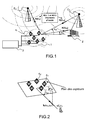
- the figure 1 shows an example of an antenna processing system which is composed of a network 1 of sensors or antennas 4i receiving signals from different sources with different arrival angles ⁇ p or ⁇ m and a receiver 3 , the figure also shows the obstacles 2 on which the signals are reflected.
- the field is more particularly that of the direction finding which consists in estimating the angles of arrival or incidences of the sources Ei (DOA for Direction Of Arrival in Anglo-Saxon).
- the elementary sensors or antennas 4i of the network which receive the signals emitted by the sources with a phase and an amplitude depending in particular on their angles of incidence and the position of the sensors.
- the angles of incidence are parameterized in a dimension 1 D by the azimuth angle ⁇ p or ⁇ m and in two dimensions 2D by the azimuth ⁇ p or ⁇ m and the elevation ⁇ p or ⁇ m .
- a 1 D direction finding is defined by techniques that estimate only the azimuth by assuming that the waves of the sources propagate in the plane of the sensor array.
- One of the objectives of antenna processing techniques is primarily to exploit the spatial diversity generated by the multi-antenna reception of incident signals by using the spatial position of network antennas to better exploit divergence in incidence and frequency. distance from sources.
- the technical field in which the object of the present patent application lies is that of direction finding in the presence of multipath resulting from the presence of obstacles placed in the path of the signals emitted by the source as illustrated in FIG. figure 3 .
- the m-th source E m propagates along paths P of incidence ⁇ mp (1 ⁇ p ⁇ M) that are caused by M-1 obstacles in the radio environment.
- One of the problems to be solved is that of multi-path direction finding of a transmitter emitting a signal which comprises at least one reference signal TSC or d (t) within a received message and which uses the knowledge of the Message formatting filter, as part of a two-way type reception system.
- the reception system is said to be two-way because it comprises two receivers 3 1 and 3 2 , which are switched alternately and periodically on a pair of antennas 4i, 4j of the sensor array as will be described in the description which follows.
- Multipath goniometry requires the implementation of a high resolution method requiring a number of reception channels strictly greater than the number of paths. More particularly, the direction finding methods using a reference signal assume that the reference signal is detected simultaneously on all the sensors. With a two-way reception system, the reference signal TSC can be seen typically on a single couple of antennas of the sensor network. Indeed, the reference signal may have a duration less than the switching time T.
- the MUSIC algorithm exploits the properties of the covariance matrix of the signal in order to estimate parameters such as the effects of the sources.
- the switching system has the disadvantage of only giving access to part of the information of the covariance matrix.
- the method according to the invention therefore consists in adapting the direction finding algorithm so as not to use the covariance matrix according to the art. earlier, but to use a matrix of direction A whose columns correspond to vectors of direction or directional vectors of each of the paths, in order to separate the different paths.
- the construction of the covariance matrix is based in particular on the knowledge of the training sequences contained in the message and also on the knowledge of the formatting filter of the linear modulation.
- the formatting filter used will be that of the linearized version of the GMSK and the learning sequences will be those TSC (Training Sequence Code), TCH (Traffic Channel) or Random Access Channel (RACH) signals.
- the method according to the invention will contain a first synchronization step which uses the symbols of the reference sequences, then the received signal is demodulated around the sequence using the shaping filter of the modulation concerned (GSM, UMTS, etc. ).
- the method may comprise an estimation step based on the estimated values of the coefficients ⁇ n and then a step where an MMSE method is applied which consists in minimizing the Euclidean distance between ⁇ n and the states ⁇ k of a constellation.
- an MMSE method is applied which consists in minimizing the Euclidean distance between ⁇ n and the states ⁇ k of a constellation.
- the method comprises a step in which one applies an algorithm MUSIC on the matrix (A . ⁇ . H) (A . ⁇ . H) H.
- linearly modulated signals which comprise a structure or a format such that includes a sequence on which a receiver can synchronize, and which is known expression of the shaping filter or filter used to modulate the symbols of the message.
- the radio-communication signals have, by their nature, reference signals in order, in particular, to build receivers or equalizers that cancel the effects of multipaths as well as those of interference. This is, for example, the case of GPS signals, radar signals that are generally composed of replicas to measure the propagation time between transmission and reception.
- FIG 5 is represented an exemplary system architecture comprising N sensors 4i in connection with a switch 10, itself connected to two receivers 3 1 , 3 2 .
- the first antenna 4 1 continuously receives a signal x 1 (t), the antenna is connected to the reference receiver 3 1.
- the signals x n (t) of the N-1 other antennas regularly commute to the second receiver 3 2, that is to say that the receiver R 2 will receive the signals received from the N-1 other antennas that are not the reference antenna.
- the signal transmitted s ( t ) by the transmitters of the switching system is in the example that of a linear modulation containing a reference signal d ( t ).
- A [ a ( ⁇ 1 ) ... a ( ⁇ M )] is the mixing matrix of the paths or sources that are also called "leading matrix”.
- the columns of this master matrix are the direction vectors of the paths.
- the multipath phenomenon is modeled in this example by specular multipaths.
- the signal emitted when it encounters an obstacle is reflected in one direction, unlike diffuse multipaths, reflected along a continuum of directions.
- Each path p is therefore associated with a single triplet ( ⁇ p , ⁇ p , ⁇ p ) respectively denoting the power, the propagation delay and the arrival angle for 1 ⁇ p ⁇ M , given that M is the number of paths.
- ⁇ at 1 ⁇ ... at NOT ⁇ T the response of the network of N antennas to a signal arriving at an angle ⁇ .
- Equation 3.1 is always checked at the antennas reception.
- the 2-way acquisition system continuously receives on the first receiver 3 1 the signal x 1 (t), while the second receiver 3 2 , because of the switching, will receive alternately the signals x 2 (t) at x N (t) for disjointed "t" time slots.
- the system makes it possible to correlate the signals x i (t) and x j (t) when i> 1 and j> 1.
- the system therefore has truncated signals and no longer all the signals received.
- An example of the signals received on the channels 1, .. i, ..N is represented at the figure 6 .
- the hatched portions correspond to the duration of reception of the signal on a given sensor.
- a ij ⁇ a ij ( ⁇ 1 ) ⁇ a ij ( ⁇ M ) ⁇ the sub-matrix of the matrix of direction A associated with the antennas i and j, since A ij contains the i th and j th lines of the matrix A.
- the switching time ⁇ t of the acquisition system will subsequently be considered zero.
- the idea implemented in the method and the system according to the invention ( figure 8 ) is to design a signal processing to reconstruct the direction matrix A (or a linearly dependent matrix of A ) to separate the M different paths.
- the method will then apply a direction finding algorithm, for example, the MUSIC type algorithm on each column of the above-mentioned direction matrix.
- the objective is to demodulate the linearly modulated signals around the reference sequence, knowing the shaping filter used during the modulation of the signal.
- This step requires knowing the position of the first modulated symbol of the sequence d (t) consisting of symbols dn in the signals received on the antennas 4 1 , ..., 4 N.
- a so-called symbol synchronization step is used here.
- the GMSK modulation can then be seen as a QPSK modulated linearly by the filter C 0 ( t ).
- TSC sequences of GSM K 26.
- the steps of the algorithm will first consist in performing symbol synchronization on the reference antenna 4 1 and then in estimating the matrix of passage between the signal x 1 ( nT s ) and the symbols c n . This will make it possible to build front and back filters which will make it possible to estimate and detect by the quadratic method, for example MMSE, the symbols on either side of the learning sequence.
- the symbols c n are estimated 21, it will be possible to estimate the channel matrix A i . ⁇ . H. , 22, on each of the commutations then to build the matrix of channel A . ⁇ . H. It will then be possible to estimate the 23 ⁇ p delays 1 ⁇ p ⁇ M from the matrix (A . ⁇ . H.) H (Ai . ⁇ .
- a more direct method of goniometry paths comprises applying a MUSIC type algorithm to the matrix (A . ⁇ . H.) (A . ⁇ . H.) H .From estimation values A i . ⁇ . H., It will also be possible to estimate the values of the angles ⁇ p from the matrix (A . ⁇ . H). H (A i . ⁇ . H.) H for i ⁇ p ⁇ M, 26.
- the synchronization criterion gives a peak that goes up to 1. This means that the hypothesis made on the length of the channel is just and that symbol synchronization works. From a practical point of view, the spreading of the channel depends, on the one hand, on the temporal spread T of the shaping filter C 0 ( t ) and on the other hand on the spreading of the channel characterized by the delays. multipaths.
- 1
- a i . ⁇ . H is the i-th line of A . ⁇ . H.
- the matrix A i . ⁇ . H is, for example, obtained in the least squares sense by minimizing the difference between x i ( nT s ) and c n AT i . ⁇ .
- a second approach for the multi-path direction finding is to separate the paths after their delay and then to goniometer them independently.
- the detection of the rank of R HH by a method known to those skilled in the art allows to know the number M of paths and deduce the projector noise ⁇ ( R HH ) of the MUSIC algorithm.
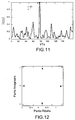
- the second approach has the advantage of being more robust to antenna calibration errors because each path is goniometrically independent, as shown in FIG. figure 12 , where the incidences of the two paths are 40 ° and 80 °.
- the method requires a good estimate of the delays ⁇ p .
Landscapes
- Engineering & Computer Science (AREA)
- Physics & Mathematics (AREA)
- General Physics & Mathematics (AREA)
- Radar, Positioning & Navigation (AREA)
- Remote Sensing (AREA)
- Power Engineering (AREA)
- Computer Networks & Wireless Communication (AREA)
- Signal Processing (AREA)
- Mathematical Physics (AREA)
- Radio Transmission System (AREA)
Claims (11)
- Verfahren zum Bestimmen der Ankunftswinkel oder der Ankunftsrichtung von mehreren Pfaden, die mit einem/r Sender oder Quelle Ei in einem N Empfangsantennen umfassenden System assoziiert sind, wobei eine der Antennen (41) eine Referenzantenne ist, die mit einem ersten Empfänger (31) kontinuierlich verbunden ist, und die N-1 anderen Antennen (4i) über einen Zweiweg-Schalter 10 mit einem zweiten Empfänger (32) diskontinuierlich verbunden sind, wobei die Referenzantenne (41) kontinuierlich ein Signal x1(t) empfängt, wobei das Signal eine Referenzsequenz d(t) umfasst, dadurch gekennzeichnet, dass es wenigstens die folgenden Schritte beinhaltet:• Durchführen einer Symbolsynchronisation an der Referenzantenne (41), dann Schätzen der Durchgangsmatrix zwischen dem an der Referenzantenne empfangenen Signal x1(nTs ) und den Referenzsymbolen dn, wobei Ts die Symbolzeit ist;• Konstruieren von zwei Filtern, die es zulassen, die Symbole cn auf beiden Seiten der Referenzsequenz d(t) bestehend aus den Symbolen dn zu schätzen und zu erkennen;• Schätzen der Kanalmatrix A 1i.Ω.H an jedem der Schalter 1 bis N auf der Basis der Kenntnis der geschätzten Symbole cn und der Signale x1(nTs ) und Konstruieren der Kanalmatrix A.Ω.H, wobei H die Kanalmatrix ist, definiert durch:
 • Schätzen des Wertes des Winkels θp auf der Basis der Kanalmatrix A.Ω.H. in der Kenntnis von:


- Verfahren nach Anspruch 1, dadurch gekennzeichnet, dass der Symbolsynchronisationsschritt wie folgt ausgeführt wird:es wird das an der Referenzantenne (41) empfangene Signal betrachtet:


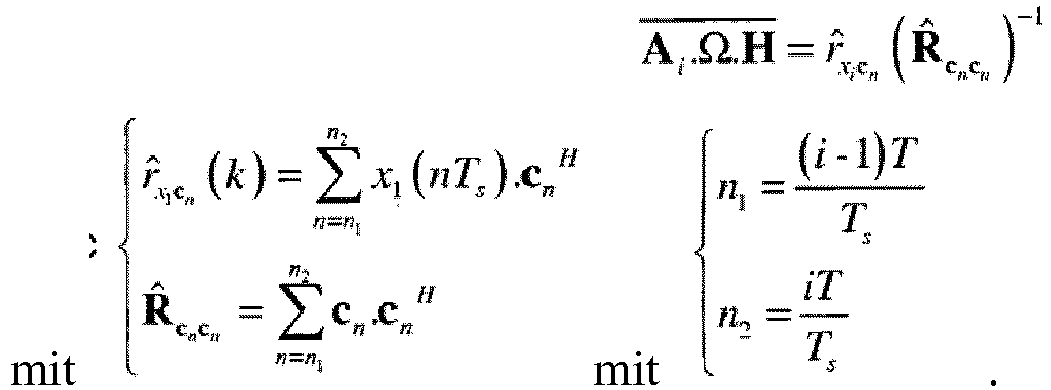
- Verfahren nach Anspruch 2, dadurch gekennzeichnet, dass nach dem Schätzen des Synchronisationsindexes i die Kanalmatrix A 1.Ω.H. durch Minimieren der Abweichung zwischen xi (nTs ) und c n geschätzt wird:
- Verfahren nach Anspruch 1, dadurch gekennzeichnet, dass für eine Demodulation auf der Basis von MMSE (Maximum Mean Square Estimator) die beiden hinteren und vorderen Filter, die benutzt werden, jeweils die folgenden Gleichungen verifizieren:
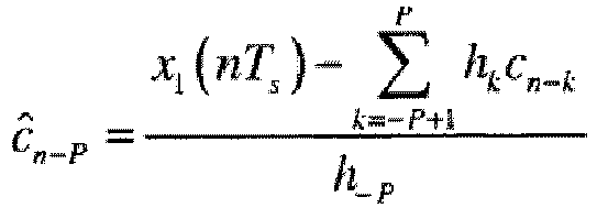

- Verfahren nach Anspruch 4, dadurch gekennzeichnet, dass es einen Schritt des Schätzens, auf der Basis von geschätzten Werten ĉn , und einen Schritt des Anwendens eines MMSE-Prozesses beinhaltet, der das Minimieren des euklidischen Abstands zwischen ĉn und den Zuständen η k einer Konstellation beinhaltet, d.h.:

- Verfahren nach Anspruch 5, dadurch gekennzeichnet, dass im Falle von GMSK, der 4 Zustände wie QPSK hat, d.h. η1 = 1, η2 = -1, η3 = j und η4 = -j, das demodulierte Symbol dann wie folgt ist:

- Verfahren nach Anspruch 5, dadurch gekennzeichnet, dass im Falle der GMSK-Modulation, bei der das Symbol-Modul |cn | = 1 verifiziert, das Verfahren einen Schritt des Verbesserns der MMSE-Berechnung beinhaltet, durch Ausführen von:

- Verfahren nach Anspruch 1, dadurch gekennzeichnet, dass die komplette Kanalmatrix A.Ω.H auf der Basis der Symbole {cn} und von kommutierten Beobachtungen geschätzt wird, die Folgendes verifizieren:

- Verfahren nach Anspruch 8, dadurch gekennzeichnet, dass die Matrix A i .Ω.H im Kleinste-Quadrate-Sinne durch Minimieren der Abweichung zwischen xi (nTs ) und c n erhalten wird, um Folgendes zu erhalten:


- Verfahren nach einem der Ansprüche 1 bis 9, dadurch gekennzeichnet, dass es wenigstens einen Schritt, bei dem ein Peilprozess auf jede der Spalten von A angewendet wird, um die Inzidenzwerte θ p jedes der Pfade zu finden, und die folgenden Schritte beinhaltet:• Schätzen der Werte der Verzögerungen τ p für 1≤p≤M, wobei M die Anzahl von Pfaden ist, auf der Basis der Matrix (A.Ω.H)H (A.Ω.H) und der Kenntnis des Vektors h(τ); und• Ermitteln, auf der Basis der Kenntnis von h(τ) und der Werte der Verzögerungen τp , einer Matrix H, und Ableiten der Matrix A oder einer linear von A abhängigen Matrix davon.
- Verfahren nach einem der Ansprüche 1 bis 9, dadurch gekennzeichnet, dass es einen Schritt beinhaltet, bei dem ein Algorithmus des MUSIC-Typs auf die Matrix (A.Ω.H)(A.Ω.H) H angewandt wird.
Applications Claiming Priority (2)
| Application Number | Priority Date | Filing Date | Title |
|---|---|---|---|
| FR0905474A FR2952725B1 (fr) | 2009-11-13 | 2009-11-13 | Procede de goniometrie de multi-trajets avec un recepteur 2 voies |
| PCT/EP2010/067229 WO2011058067A1 (fr) | 2009-11-13 | 2010-11-10 | Procede de goniometrie de multi-trajets avec un recepteur 2 voies |
Publications (2)
| Publication Number | Publication Date |
|---|---|
| EP2499511A1 EP2499511A1 (de) | 2012-09-19 |
| EP2499511B1 true EP2499511B1 (de) | 2016-03-16 |
Family
ID=42290124
Family Applications (1)
| Application Number | Title | Priority Date | Filing Date |
|---|---|---|---|
| EP10773932.8A Not-in-force EP2499511B1 (de) | 2009-11-13 | 2010-11-10 | Verfahren zur messung der winkel von mehreren wegen mit einem zweiwege-empfänger |
Country Status (5)
| Country | Link |
|---|---|
| EP (1) | EP2499511B1 (de) |
| FR (1) | FR2952725B1 (de) |
| IL (1) | IL219749A0 (de) |
| PL (1) | PL2499511T3 (de) |
| WO (1) | WO2011058067A1 (de) |
Families Citing this family (1)
| Publication number | Priority date | Publication date | Assignee | Title |
|---|---|---|---|---|
| DE102015122420A1 (de) | 2015-12-21 | 2017-06-22 | Fraunhofer-Gesellschaft zur Förderung der angewandten Forschung e.V. | Sendeanordnung zum Erzeugen eines für eine Lokalisierung geeigneten Signalmusters und Empfangsanordnung zum Durchführen einer Lokalisierung |
Family Cites Families (5)
| Publication number | Priority date | Publication date | Assignee | Title |
|---|---|---|---|---|
| US5583517A (en) * | 1992-08-20 | 1996-12-10 | Nexus 1994 Limited | Multi-path resistant frequency-hopped spread spectrum mobile location system |
| US6489923B1 (en) * | 1999-09-16 | 2002-12-03 | Nortel Networks Limited | Position location method and apparatus for a mobile telecommunications system |
| FR2805614B1 (fr) | 2000-02-25 | 2003-08-22 | Thomson Csf | Procede de localisation de sources radioelectriques au moyen d'un radiogoniometre haute resolution deux voies |
| FR2829325B1 (fr) | 2001-09-05 | 2005-06-17 | Thales Sa | Procede et dispositif de detection de sources dans un systeme de communication |
| FR2829241B1 (fr) | 2001-09-05 | 2006-07-21 | Thales Sa | Procede et dispositif de radiogoniometrie cooperative en transmission |
-
2009
- 2009-11-13 FR FR0905474A patent/FR2952725B1/fr not_active Expired - Fee Related
-
2010
- 2010-11-10 PL PL10773932.8T patent/PL2499511T3/pl unknown
- 2010-11-10 WO PCT/EP2010/067229 patent/WO2011058067A1/fr not_active Ceased
- 2010-11-10 EP EP10773932.8A patent/EP2499511B1/de not_active Not-in-force
-
2012
- 2012-05-13 IL IL219749A patent/IL219749A0/en unknown
Also Published As
| Publication number | Publication date |
|---|---|
| FR2952725B1 (fr) | 2011-12-30 |
| EP2499511A1 (de) | 2012-09-19 |
| IL219749A0 (en) | 2012-07-31 |
| FR2952725A1 (fr) | 2011-05-20 |
| PL2499511T3 (pl) | 2016-10-31 |
| WO2011058067A1 (fr) | 2011-05-19 |
Similar Documents
| Publication | Publication Date | Title |
|---|---|---|
| EP1259833B1 (de) | Verfahren zum orten von funkquellen mittels eines hochauflösenden zweikanaligen funkpeilers | |
| EP2368133B1 (de) | Verfahren zum lokalisieren mehrerer strahlen einer quelle mit oder ohne aoa durch mehrkanalschätzung von tdoa und fdoa | |
| EP2428810B1 (de) | Geo-Lokalisierungsverfahren mit mehreren Sender mit räumlich-zeitlicher Behandlung | |
| EP2579063B1 (de) | Verfahren und System zur Lokalisierung von Interferenzen durch Frequenz-Subbasisband | |
| EP2223153B1 (de) | Verfahren und system zur unterstüzung von umweltcharakterisierung mittels ultrabreitband-hochfrequenzsignalen | |
| EP2176680B1 (de) | Verfahren und vorrichtungen zu bestimmung der impulsreaktion von übertragungskanälen mit fixen oder mobilen sendern, reflektoren und sensoren | |
| EP3203267B1 (de) | Kalibriermethode eines satelliten-funknavigationsempfängers | |
| EP0926510B1 (de) | Verfahren zur Positionsbestimmung von mobilen Objekten im Stadtverkehr | |
| EP2517037B1 (de) | Verfahren zur kalkulation der anzahl von störquellen einer sensoranordnung mittels kalkulation von rauschstatistiken | |
| EP1582888B1 (de) | Verfahren zur breitbandigen blinden Ortung von einem oder mehreren Sendern durch einen sich vorbeibewegenden Träger | |
| EP1291664B1 (de) | Verfahren und Vorrichtung zur kooperativen Funkpeilung im Übertragungsmodus | |
| EP1253435B1 (de) | Verfahren und Vorrichtung zur Raum-Zeitschätzung von einem oder mehrerer Sendern | |
| EP3543745B1 (de) | Multiantennenvorrichtung für die unterdrückung von mehrwegesignalen in einem satelliten-navigationssystem, und entsprechendes verfahren | |
| EP2499511B1 (de) | Verfahren zur messung der winkel von mehreren wegen mit einem zweiwege-empfänger | |
| EP2851703A1 (de) | Verfahren, bei dem gleichzeitig die Synchronisation, Identifikation, Messung und Schätzung des Ausbreitungsfilters und die Lokalisierung der nützlichen und interferierenden Sender stattfindet | |
| EP2607915B1 (de) | Lokalisierungsverfahren von Sendequellen durch Ausnutzung der Transformatorkopplung eines Antennennetzes mit kleiner Basis, und Einkanal-Empfangssystem mit langsamer Umschaltung zur Umsetzung dieses Verfahrens | |
| EP2857856B1 (de) | Goniometrieverfahren mit einem System, das über weniger Empfangswege als Sensoren verfügt | |
| EP2607916B1 (de) | Lokalisierungsverfahren von Sendequellen durch Ausnutzung der Transformatorkopplung eines Antennennetzes mit kleiner Basis, und Einkanal-Empfangssystem mit schneller Umschaltung zur Umsetzung dieses Verfahrens | |
| EP1229696A1 (de) | Schätzung der Kanalparameter mittels Maximalwahrscheinlichkeitsschätzung | |
| Rouseff et al. | Underwater acoustic communication using passive phase conjugation | |
| EP1221792A1 (de) | Verfahren und Empfänger zur adaptiven Schätzung der Raum-Zeit-Parametern eines Kanal | |
| EP3074783B1 (de) | System und verfahren zur ortung aufgefangener sonarübertragungen | |
| EP4124877A1 (de) | Verfahren zur analyse von durch ein elektromagnetisches empfangssystem abgefangenen signalen und entsprechendes system | |
| EP2743720A1 (de) | Verfahren zur Positionsbestimmung eines Senders ohne Verwendung einer Referenzstrecke | |
| CA2586008A1 (fr) | Procede pour caracteriser les emetteurs par association de parametres lies a un meme emetteur radio-electrique |
Legal Events
| Date | Code | Title | Description |
|---|---|---|---|
| PUAI | Public reference made under article 153(3) epc to a published international application that has entered the european phase |
Free format text: ORIGINAL CODE: 0009012 |
|
| 17P | Request for examination filed |
Effective date: 20120511 |
|
| AK | Designated contracting states |
Kind code of ref document: A1 Designated state(s): AL AT BE BG CH CY CZ DE DK EE ES FI FR GB GR HR HU IE IS IT LI LT LU LV MC MK MT NL NO PL PT RO RS SE SI SK SM TR |
|
| DAX | Request for extension of the european patent (deleted) | ||
| 17Q | First examination report despatched |
Effective date: 20130603 |
|
| GRAP | Despatch of communication of intention to grant a patent |
Free format text: ORIGINAL CODE: EPIDOSNIGR1 |
|
| INTG | Intention to grant announced |
Effective date: 20150918 |
|
| GRAS | Grant fee paid |
Free format text: ORIGINAL CODE: EPIDOSNIGR3 |
|
| GRAA | (expected) grant |
Free format text: ORIGINAL CODE: 0009210 |
|
| AK | Designated contracting states |
Kind code of ref document: B1 Designated state(s): AL AT BE BG CH CY CZ DE DK EE ES FI FR GB GR HR HU IE IS IT LI LT LU LV MC MK MT NL NO PL PT RO RS SE SI SK SM TR |
|
| REG | Reference to a national code |
Ref country code: GB Ref legal event code: FG4D Free format text: NOT ENGLISH |
|
| REG | Reference to a national code |
Ref country code: CH Ref legal event code: EP |
|
| REG | Reference to a national code |
Ref country code: IE Ref legal event code: FG4D Free format text: LANGUAGE OF EP DOCUMENT: FRENCH |
|
| REG | Reference to a national code |
Ref country code: AT Ref legal event code: REF Ref document number: 781703 Country of ref document: AT Kind code of ref document: T Effective date: 20160415 |
|
| REG | Reference to a national code |
Ref country code: DE Ref legal event code: R096 Ref document number: 602010031244 Country of ref document: DE |
|
| REG | Reference to a national code |
Ref country code: CH Ref legal event code: NV Representative=s name: MARKS AND CLERK (LUXEMBOURG) LLP, CH |
|
| REG | Reference to a national code |
Ref country code: SE Ref legal event code: TRGR |
|
| REG | Reference to a national code |
Ref country code: NL Ref legal event code: MP Effective date: 20160316 |
|
| REG | Reference to a national code |
Ref country code: LT Ref legal event code: MG4D |
|
| PG25 | Lapsed in a contracting state [announced via postgrant information from national office to epo] |
Ref country code: HR Free format text: LAPSE BECAUSE OF FAILURE TO SUBMIT A TRANSLATION OF THE DESCRIPTION OR TO PAY THE FEE WITHIN THE PRESCRIBED TIME-LIMIT Effective date: 20160316 Ref country code: NO Free format text: LAPSE BECAUSE OF FAILURE TO SUBMIT A TRANSLATION OF THE DESCRIPTION OR TO PAY THE FEE WITHIN THE PRESCRIBED TIME-LIMIT Effective date: 20160616 Ref country code: GR Free format text: LAPSE BECAUSE OF FAILURE TO SUBMIT A TRANSLATION OF THE DESCRIPTION OR TO PAY THE FEE WITHIN THE PRESCRIBED TIME-LIMIT Effective date: 20160617 |
|
| REG | Reference to a national code |
Ref country code: AT Ref legal event code: MK05 Ref document number: 781703 Country of ref document: AT Kind code of ref document: T Effective date: 20160316 |
|
| PG25 | Lapsed in a contracting state [announced via postgrant information from national office to epo] |
Ref country code: RS Free format text: LAPSE BECAUSE OF FAILURE TO SUBMIT A TRANSLATION OF THE DESCRIPTION OR TO PAY THE FEE WITHIN THE PRESCRIBED TIME-LIMIT Effective date: 20160316 Ref country code: NL Free format text: LAPSE BECAUSE OF FAILURE TO SUBMIT A TRANSLATION OF THE DESCRIPTION OR TO PAY THE FEE WITHIN THE PRESCRIBED TIME-LIMIT Effective date: 20160316 Ref country code: LT Free format text: LAPSE BECAUSE OF FAILURE TO SUBMIT A TRANSLATION OF THE DESCRIPTION OR TO PAY THE FEE WITHIN THE PRESCRIBED TIME-LIMIT Effective date: 20160316 Ref country code: LV Free format text: LAPSE BECAUSE OF FAILURE TO SUBMIT A TRANSLATION OF THE DESCRIPTION OR TO PAY THE FEE WITHIN THE PRESCRIBED TIME-LIMIT Effective date: 20160316 |
|
| REG | Reference to a national code |
Ref country code: FR Ref legal event code: PLFP Year of fee payment: 7 |
|
| PG25 | Lapsed in a contracting state [announced via postgrant information from national office to epo] |
Ref country code: IS Free format text: LAPSE BECAUSE OF FAILURE TO SUBMIT A TRANSLATION OF THE DESCRIPTION OR TO PAY THE FEE WITHIN THE PRESCRIBED TIME-LIMIT Effective date: 20160716 Ref country code: EE Free format text: LAPSE BECAUSE OF FAILURE TO SUBMIT A TRANSLATION OF THE DESCRIPTION OR TO PAY THE FEE WITHIN THE PRESCRIBED TIME-LIMIT Effective date: 20160316 |
|
| PG25 | Lapsed in a contracting state [announced via postgrant information from national office to epo] |
Ref country code: PT Free format text: LAPSE BECAUSE OF FAILURE TO SUBMIT A TRANSLATION OF THE DESCRIPTION OR TO PAY THE FEE WITHIN THE PRESCRIBED TIME-LIMIT Effective date: 20160718 Ref country code: ES Free format text: LAPSE BECAUSE OF FAILURE TO SUBMIT A TRANSLATION OF THE DESCRIPTION OR TO PAY THE FEE WITHIN THE PRESCRIBED TIME-LIMIT Effective date: 20160316 Ref country code: SK Free format text: LAPSE BECAUSE OF FAILURE TO SUBMIT A TRANSLATION OF THE DESCRIPTION OR TO PAY THE FEE WITHIN THE PRESCRIBED TIME-LIMIT Effective date: 20160316 Ref country code: AT Free format text: LAPSE BECAUSE OF FAILURE TO SUBMIT A TRANSLATION OF THE DESCRIPTION OR TO PAY THE FEE WITHIN THE PRESCRIBED TIME-LIMIT Effective date: 20160316 Ref country code: RO Free format text: LAPSE BECAUSE OF FAILURE TO SUBMIT A TRANSLATION OF THE DESCRIPTION OR TO PAY THE FEE WITHIN THE PRESCRIBED TIME-LIMIT Effective date: 20160316 Ref country code: CZ Free format text: LAPSE BECAUSE OF FAILURE TO SUBMIT A TRANSLATION OF THE DESCRIPTION OR TO PAY THE FEE WITHIN THE PRESCRIBED TIME-LIMIT Effective date: 20160316 Ref country code: SM Free format text: LAPSE BECAUSE OF FAILURE TO SUBMIT A TRANSLATION OF THE DESCRIPTION OR TO PAY THE FEE WITHIN THE PRESCRIBED TIME-LIMIT Effective date: 20160316 |
|
| REG | Reference to a national code |
Ref country code: DE Ref legal event code: R097 Ref document number: 602010031244 Country of ref document: DE |
|
| PG25 | Lapsed in a contracting state [announced via postgrant information from national office to epo] |
Ref country code: IT Free format text: LAPSE BECAUSE OF FAILURE TO SUBMIT A TRANSLATION OF THE DESCRIPTION OR TO PAY THE FEE WITHIN THE PRESCRIBED TIME-LIMIT Effective date: 20160316 |
|
| PGFP | Annual fee paid to national office [announced via postgrant information from national office to epo] |
Ref country code: LU Payment date: 20161027 Year of fee payment: 7 |
|
| PLBE | No opposition filed within time limit |
Free format text: ORIGINAL CODE: 0009261 |
|
| STAA | Information on the status of an ep patent application or granted ep patent |
Free format text: STATUS: NO OPPOSITION FILED WITHIN TIME LIMIT |
|
| PG25 | Lapsed in a contracting state [announced via postgrant information from national office to epo] |
Ref country code: DK Free format text: LAPSE BECAUSE OF FAILURE TO SUBMIT A TRANSLATION OF THE DESCRIPTION OR TO PAY THE FEE WITHIN THE PRESCRIBED TIME-LIMIT Effective date: 20160316 |
|
| PGFP | Annual fee paid to national office [announced via postgrant information from national office to epo] |
Ref country code: CH Payment date: 20161115 Year of fee payment: 7 Ref country code: FR Payment date: 20161028 Year of fee payment: 7 Ref country code: DE Payment date: 20161101 Year of fee payment: 7 Ref country code: FI Payment date: 20161109 Year of fee payment: 7 Ref country code: GB Payment date: 20161027 Year of fee payment: 7 |
|
| 26N | No opposition filed |
Effective date: 20161219 |
|
| PG25 | Lapsed in a contracting state [announced via postgrant information from national office to epo] |
Ref country code: BG Free format text: LAPSE BECAUSE OF FAILURE TO SUBMIT A TRANSLATION OF THE DESCRIPTION OR TO PAY THE FEE WITHIN THE PRESCRIBED TIME-LIMIT Effective date: 20160616 |
|
| PGFP | Annual fee paid to national office [announced via postgrant information from national office to epo] |
Ref country code: BE Payment date: 20161024 Year of fee payment: 7 Ref country code: SE Payment date: 20161111 Year of fee payment: 7 Ref country code: PL Payment date: 20161103 Year of fee payment: 7 |
|
| PG25 | Lapsed in a contracting state [announced via postgrant information from national office to epo] |
Ref country code: SI Free format text: LAPSE BECAUSE OF FAILURE TO SUBMIT A TRANSLATION OF THE DESCRIPTION OR TO PAY THE FEE WITHIN THE PRESCRIBED TIME-LIMIT Effective date: 20160316 |
|
| REG | Reference to a national code |
Ref country code: IE Ref legal event code: MM4A |
|
| PG25 | Lapsed in a contracting state [announced via postgrant information from national office to epo] |
Ref country code: IE Free format text: LAPSE BECAUSE OF NON-PAYMENT OF DUE FEES Effective date: 20161110 |
|
| PG25 | Lapsed in a contracting state [announced via postgrant information from national office to epo] |
Ref country code: HU Free format text: LAPSE BECAUSE OF FAILURE TO SUBMIT A TRANSLATION OF THE DESCRIPTION OR TO PAY THE FEE WITHIN THE PRESCRIBED TIME-LIMIT; INVALID AB INITIO Effective date: 20101110 Ref country code: CY Free format text: LAPSE BECAUSE OF FAILURE TO SUBMIT A TRANSLATION OF THE DESCRIPTION OR TO PAY THE FEE WITHIN THE PRESCRIBED TIME-LIMIT Effective date: 20160316 |
|
| REG | Reference to a national code |
Ref country code: DE Ref legal event code: R119 Ref document number: 602010031244 Country of ref document: DE |
|
| PG25 | Lapsed in a contracting state [announced via postgrant information from national office to epo] |
Ref country code: MC Free format text: LAPSE BECAUSE OF FAILURE TO SUBMIT A TRANSLATION OF THE DESCRIPTION OR TO PAY THE FEE WITHIN THE PRESCRIBED TIME-LIMIT Effective date: 20160316 Ref country code: TR Free format text: LAPSE BECAUSE OF FAILURE TO SUBMIT A TRANSLATION OF THE DESCRIPTION OR TO PAY THE FEE WITHIN THE PRESCRIBED TIME-LIMIT Effective date: 20160316 Ref country code: MK Free format text: LAPSE BECAUSE OF FAILURE TO SUBMIT A TRANSLATION OF THE DESCRIPTION OR TO PAY THE FEE WITHIN THE PRESCRIBED TIME-LIMIT Effective date: 20160316 |
|
| REG | Reference to a national code |
Ref country code: SE Ref legal event code: EUG |
|
| GBPC | Gb: european patent ceased through non-payment of renewal fee |
Effective date: 20171110 |
|
| PG25 | Lapsed in a contracting state [announced via postgrant information from national office to epo] |
Ref country code: FI Free format text: LAPSE BECAUSE OF NON-PAYMENT OF DUE FEES Effective date: 20171110 Ref country code: LI Free format text: LAPSE BECAUSE OF NON-PAYMENT OF DUE FEES Effective date: 20171130 Ref country code: CH Free format text: LAPSE BECAUSE OF NON-PAYMENT OF DUE FEES Effective date: 20171130 |
|
| PG25 | Lapsed in a contracting state [announced via postgrant information from national office to epo] |
Ref country code: SE Free format text: LAPSE BECAUSE OF NON-PAYMENT OF DUE FEES Effective date: 20171111 Ref country code: LU Free format text: LAPSE BECAUSE OF NON-PAYMENT OF DUE FEES Effective date: 20171110 |
|
| REG | Reference to a national code |
Ref country code: FR Ref legal event code: ST Effective date: 20180731 Ref country code: BE Ref legal event code: MM Effective date: 20171130 |
|
| PG25 | Lapsed in a contracting state [announced via postgrant information from national office to epo] |
Ref country code: MT Free format text: LAPSE BECAUSE OF FAILURE TO SUBMIT A TRANSLATION OF THE DESCRIPTION OR TO PAY THE FEE WITHIN THE PRESCRIBED TIME-LIMIT Effective date: 20160316 |
|
| PG25 | Lapsed in a contracting state [announced via postgrant information from national office to epo] |
Ref country code: FR Free format text: LAPSE BECAUSE OF NON-PAYMENT OF DUE FEES Effective date: 20171130 Ref country code: AL Free format text: LAPSE BECAUSE OF FAILURE TO SUBMIT A TRANSLATION OF THE DESCRIPTION OR TO PAY THE FEE WITHIN THE PRESCRIBED TIME-LIMIT Effective date: 20160316 Ref country code: DE Free format text: LAPSE BECAUSE OF NON-PAYMENT OF DUE FEES Effective date: 20180602 |
|
| PG25 | Lapsed in a contracting state [announced via postgrant information from national office to epo] |
Ref country code: BE Free format text: LAPSE BECAUSE OF NON-PAYMENT OF DUE FEES Effective date: 20171130 Ref country code: GB Free format text: LAPSE BECAUSE OF NON-PAYMENT OF DUE FEES Effective date: 20171110 |
|
| PG25 | Lapsed in a contracting state [announced via postgrant information from national office to epo] |
Ref country code: PL Free format text: LAPSE BECAUSE OF NON-PAYMENT OF DUE FEES Effective date: 20171110 |