EP2500102A1 - Dispositif de flottation avec un élément de distribution d'un fluide pouvant générer un courant du fluide vers le collecteur en mousse - Google Patents
Dispositif de flottation avec un élément de distribution d'un fluide pouvant générer un courant du fluide vers le collecteur en mousse Download PDFInfo
- Publication number
- EP2500102A1 EP2500102A1 EP20110158298 EP11158298A EP2500102A1 EP 2500102 A1 EP2500102 A1 EP 2500102A1 EP 20110158298 EP20110158298 EP 20110158298 EP 11158298 A EP11158298 A EP 11158298A EP 2500102 A1 EP2500102 A1 EP 2500102A1
- Authority
- EP
- European Patent Office
- Prior art keywords
- foam product
- flotation
- suspension
- foam
- bubbles
- Prior art date
- Legal status (The legal status is an assumption and is not a legal conclusion. Google has not performed a legal analysis and makes no representation as to the accuracy of the status listed.)
- Granted
Links
- 238000005188 flotation Methods 0.000 title claims abstract description 124
- 239000012530 fluid Substances 0.000 title claims abstract description 111
- 239000006260 foam Substances 0.000 claims abstract description 155
- 239000000725 suspension Substances 0.000 claims abstract description 80
- 238000007599 discharging Methods 0.000 claims abstract description 9
- 239000002245 particle Substances 0.000 claims description 32
- 238000000034 method Methods 0.000 claims description 21
- 230000001105 regulatory effect Effects 0.000 claims description 16
- 239000007787 solid Substances 0.000 claims description 16
- 239000000463 material Substances 0.000 claims description 9
- 229910052500 inorganic mineral Inorganic materials 0.000 claims description 5
- 239000011707 mineral Substances 0.000 claims description 5
- 230000015572 biosynthetic process Effects 0.000 claims description 4
- 230000001276 controlling effect Effects 0.000 claims description 2
- 208000002352 blister Diseases 0.000 description 12
- 230000002209 hydrophobic effect Effects 0.000 description 7
- 239000007788 liquid Substances 0.000 description 4
- 230000009172 bursting Effects 0.000 description 3
- 239000003153 chemical reaction reagent Substances 0.000 description 3
- 238000005755 formation reaction Methods 0.000 description 3
- 229910052751 metal Inorganic materials 0.000 description 3
- 239000002184 metal Substances 0.000 description 3
- XEEYBQQBJWHFJM-UHFFFAOYSA-N Iron Chemical compound [Fe] XEEYBQQBJWHFJM-UHFFFAOYSA-N 0.000 description 2
- 238000005276 aerator Methods 0.000 description 2
- 238000004581 coalescence Methods 0.000 description 2
- 238000005457 optimization Methods 0.000 description 2
- 238000011084 recovery Methods 0.000 description 2
- 238000000926 separation method Methods 0.000 description 2
- XLYOFNOQVPJJNP-UHFFFAOYSA-N water Substances O XLYOFNOQVPJJNP-UHFFFAOYSA-N 0.000 description 2
- RYGMFSIKBFXOCR-UHFFFAOYSA-N Copper Chemical compound [Cu] RYGMFSIKBFXOCR-UHFFFAOYSA-N 0.000 description 1
- 230000001133 acceleration Effects 0.000 description 1
- 238000005273 aeration Methods 0.000 description 1
- 230000001174 ascending effect Effects 0.000 description 1
- 229910052802 copper Inorganic materials 0.000 description 1
- 239000010949 copper Substances 0.000 description 1
- 230000007423 decrease Effects 0.000 description 1
- 230000001419 dependent effect Effects 0.000 description 1
- 230000002349 favourable effect Effects 0.000 description 1
- -1 ferrous metals Chemical class 0.000 description 1
- 239000006261 foam material Substances 0.000 description 1
- 238000005187 foaming Methods 0.000 description 1
- 238000007654 immersion Methods 0.000 description 1
- 238000002347 injection Methods 0.000 description 1
- 239000007924 injection Substances 0.000 description 1
- 229910052742 iron Inorganic materials 0.000 description 1
- 238000005259 measurement Methods 0.000 description 1
- 239000012528 membrane Substances 0.000 description 1
- 239000006262 metallic foam Substances 0.000 description 1
- 150000002739 metals Chemical class 0.000 description 1
- 239000000203 mixture Substances 0.000 description 1
- 238000012544 monitoring process Methods 0.000 description 1
- 230000003287 optical effect Effects 0.000 description 1
- 239000013618 particulate matter Substances 0.000 description 1
- 239000011148 porous material Substances 0.000 description 1
- 239000010970 precious metal Substances 0.000 description 1
- 230000002028 premature Effects 0.000 description 1
- 239000002002 slurry Substances 0.000 description 1
- 239000000126 substance Substances 0.000 description 1
- PTISTKLWEJDJID-UHFFFAOYSA-N sulfanylidenemolybdenum Chemical class [Mo]=S PTISTKLWEJDJID-UHFFFAOYSA-N 0.000 description 1
- 239000012991 xanthate Substances 0.000 description 1
Images


Classifications
-
- B—PERFORMING OPERATIONS; TRANSPORTING
- B03—SEPARATION OF SOLID MATERIALS USING LIQUIDS OR USING PNEUMATIC TABLES OR JIGS; MAGNETIC OR ELECTROSTATIC SEPARATION OF SOLID MATERIALS FROM SOLID MATERIALS OR FLUIDS; SEPARATION BY HIGH-VOLTAGE ELECTRIC FIELDS
- B03D—FLOTATION; DIFFERENTIAL SEDIMENTATION
- B03D1/00—Flotation
- B03D1/02—Froth-flotation processes
- B03D1/028—Control and monitoring of flotation processes; computer models therefor
-
- B—PERFORMING OPERATIONS; TRANSPORTING
- B03—SEPARATION OF SOLID MATERIALS USING LIQUIDS OR USING PNEUMATIC TABLES OR JIGS; MAGNETIC OR ELECTROSTATIC SEPARATION OF SOLID MATERIALS FROM SOLID MATERIALS OR FLUIDS; SEPARATION BY HIGH-VOLTAGE ELECTRIC FIELDS
- B03D—FLOTATION; DIFFERENTIAL SEDIMENTATION
- B03D1/00—Flotation
- B03D1/14—Flotation machines
- B03D1/1443—Feed or discharge mechanisms for flotation tanks
- B03D1/1456—Feed mechanisms for the slurry
-
- B—PERFORMING OPERATIONS; TRANSPORTING
- B03—SEPARATION OF SOLID MATERIALS USING LIQUIDS OR USING PNEUMATIC TABLES OR JIGS; MAGNETIC OR ELECTROSTATIC SEPARATION OF SOLID MATERIALS FROM SOLID MATERIALS OR FLUIDS; SEPARATION BY HIGH-VOLTAGE ELECTRIC FIELDS
- B03D—FLOTATION; DIFFERENTIAL SEDIMENTATION
- B03D1/00—Flotation
- B03D1/14—Flotation machines
- B03D1/1443—Feed or discharge mechanisms for flotation tanks
- B03D1/1462—Discharge mechanisms for the froth
-
- B—PERFORMING OPERATIONS; TRANSPORTING
- B03—SEPARATION OF SOLID MATERIALS USING LIQUIDS OR USING PNEUMATIC TABLES OR JIGS; MAGNETIC OR ELECTROSTATIC SEPARATION OF SOLID MATERIALS FROM SOLID MATERIALS OR FLUIDS; SEPARATION BY HIGH-VOLTAGE ELECTRIC FIELDS
- B03D—FLOTATION; DIFFERENTIAL SEDIMENTATION
- B03D1/00—Flotation
- B03D1/14—Flotation machines
- B03D1/1493—Flotation machines with means for establishing a specified flow pattern
-
- B—PERFORMING OPERATIONS; TRANSPORTING
- B03—SEPARATION OF SOLID MATERIALS USING LIQUIDS OR USING PNEUMATIC TABLES OR JIGS; MAGNETIC OR ELECTROSTATIC SEPARATION OF SOLID MATERIALS FROM SOLID MATERIALS OR FLUIDS; SEPARATION BY HIGH-VOLTAGE ELECTRIC FIELDS
- B03D—FLOTATION; DIFFERENTIAL SEDIMENTATION
- B03D1/00—Flotation
- B03D1/14—Flotation machines
- B03D1/24—Pneumatic
- B03D1/26—Air lift machines
Definitions
- the invention relates to a housing comprising a flotation chamber for receiving a suspension and at least one inlet for the suspension, and at least one foam collecting device for receiving and discharging a foam product, which is arranged on an upper side of the housing.
- the invention further relates to a method for discharging a foam product formed in such a flotation device, wherein the flotation chamber is at least partially filled with suspension, wherein the suspension is fumigated and the foam product forms from gas bubbles and solid particles adhering thereto, which adheres to a surface of the suspension collects and is discharged via the at least one foam collecting device.
- Flotation is a physical separation process for separating fine-grained mixtures of solids, such as ores and gangue, in an aqueous slurry by means of gas bubbles due to a different surface wettability of the particles contained in the suspension. It is used for the treatment of mineral resources and in the processing of preferably mineral substances with a low to moderate content of a useful component or a valuable material, for example in the form of non-ferrous metals, iron, metals of rare earths and / or precious metals and non-metallic mineral resources.
- a suspension of water and fine-grained solid mixed with reagents is generally introduced into a flotation chamber via at least one nozzle arrangement.
- the purpose of the reagents is to ensure that, in particular, the valuable particles or valuable material particles which are preferably to be separated off are made hydrophobic in the suspension become.
- xanthates are used as reagents, in particular to selectively hydrophobize sulfidic ore particles.
- the at least one nozzle arrangement is supplied with gas, in particular with air, which comes into contact with the hydrophobic particles in the suspension.
- the hydrophobic particles adhere to forming gas bubbles, so that the gas bubble structures, also called aeroflocs, float and form the foam product on the surface of the suspension.
- the foam product is discharged into a collecting container and usually thickened.
- the quality of the foam product or the separation efficiency of the flotation process depends inter alia on the probability of collision between a hydrophobic particle and a gas bubble.
- a preferred diameter of the gas bubbles is less than about 5 mm and is in particular in the range between 1 and 5 mm.
- Such small gas bubbles have a high specific surface area and are therefore able to bind and take up significantly more valuable material particles, in particular ore particles, per amount of gas used than larger gas bubbles are capable of doing.
- gas bubbles larger in diameter increase faster than gas bubbles of smaller diameter.
- the smaller gas bubbles are collected by larger gas bubbles and combine with them to even larger gas bubbles. This reduces the available specific surface of the gas bubbles in the suspension, can be bound to the valuable particles.
- hybrid flotation cells which represent a combination of a pneumatic flotation cell with a columnar flotation cell
- larger particulate matter having particle diameters in the range of 50 microns and larger are not completely bound to the existing gas bubbles and thus can only be partially separated from the suspension. Fines with particle diameters in the range of 20 microns and less, however, are particularly well deposited.
- the performance of a flotation device also depends on the efficiency of a removal of the foam product formed from the surface of the suspension. So-called dead zones often form in flotation devices in which only vertical transport processes take place between the suspension and the foam product floating thereon. The application of solid particles to be separated is reduced in the dead zones, since the bubbles of the foam product stay there too long and burst already on site. Thus, solid particles formerly bound to such a burst bubble sink back into the suspension and can not be discharged as a foam product.
- the WO 2006/069995 A1 describes a pneumatic flotation cell having a housing comprising a flotation chamber with at least one nozzle arrangement for feeding suspension into the flotation chamber, here referred to as ejectors, furthermore with at least a feed arrangement for feeding gas into the flotation chamber, when using air aeration devices or aerators, and a collecting container for a foam product formed in the flotation.
- the foam product is ideally pushed away by the incoming foam and runs into a foam collecting channel.
- the US 6,095,336 and the WO 1993/20945 A1 describe flotation cells with a network of permanently installed foam collecting troughs, which are intended to remove the foam product as quickly as possible at each location of the surface of the suspension.
- the RU 2397818 C1 describes a flotation device in which a gas flow is blown towards a foam collecting channel on the surface of the suspension in order to accelerate the foam product towards the foam collecting channel.
- the US 6,926,154 B2 describes a flotation machine comprising a rotating device for foam product removal, which at least partially immersed in the foam and pushes it mechanically towards the foam collecting channel.
- the three last-mentioned, active systems for accelerating the removal of the foam product usually have such high shear forces on the foam product that this leads to premature bursting of bubbles and thus also to a reduced yield of foam product.
- the object is achieved for the flotation device by comprising a housing with a flotation chamber for receiving a suspension and at least one inlet for the suspension, and at least one foam collecting device for receiving and discharging a foam product, which is arranged on an upper side of the housing wherein at least one fluid distribution element for generating a directed towards the at least one foam collection device flow is present above the at least one inlet in the flotation chamber, the vertical position is variable above the inlet in the flotation chamber.
- the object is for the method for discharging a foam product formed in a flotation device according to the invention, wherein the flotation is at least partially filled with suspension, wherein the suspension is fumigated and the foam product forms from gas bubbles and adhering solid particles, which forms on a surface of the suspension collects and discharged via the at least one foam collecting device, achieved by means of the at least one fluid distribution element generates a flow in the direction of the at least one foam collecting device and the vertical position of the at least one fluid distribution element in the flotation is adjusted depending on a level of the flotation chamber with suspension.
- the flotation device has the advantage that the vertical position of the at least one fluid distribution element above the inlet into the flotation chamber is variable and thus adjustable to a level of suspension in the upper part of the flotation chamber.
- a fluid distributor element can optimally act at the interface or across the interface between the foam and the suspension, thereby enabling a particularly gentle acceleration of the foam product in the direction of the foam collecting device. It gets through that out of one Fluid distribution element fluid flowing out of the foam and / or displaced the suspension and pushed in the direction of a foam collection device. This can be done at relatively low outflow velocities of the fluid, so that no bubbles burst prematurely.
- a fluid distribution element is arranged in particular adjacent to an area in the flotation chamber, in which would be located without the fluid distribution element, a dead zone in which take place only vertical transport operations between the suspension and the foam product floating thereon.
- the fluid either gas, especially air, can be used or a liquid, in particular water, are flowed.
- the vertical position of the at least one fluid distribution element is adjusted such that at least a portion of a fluid discharged from the at least one fluid distribution element immediately adjacent to the surface of the suspension flows directly into the suspension.
- fluid distribution elements for introducing gas and / or for introducing liquid can be present at the same time.
- the flotation chamber has a vertical central axis and the at least one foam collecting device annular and concentric with the central axis is arranged, wherein the at least one fluid distribution element for generating a, directed away from the central axis in the direction of the at least one annular foam collecting device flow is established.
- a plurality of concentrically arranged, annular foam collecting devices may be present, each of which is assigned at least one fluid distribution element.
- the circumference of the flotation chamber can have different shapes, such as a rectangle, a circle, an ellipse, etc., although here the circular shape is preferred.
- the flotation machine is preferably a pneumatic flotation cell, a columnar flotation cell or a hybrid flotation cell, in which both types are combined.
- the at least one fluid distributor element is preferably set up to generate a flow directed radially from the central axis of the flotation chamber. This minimizes the way a bubble of the foam product must travel. The time to reach the foam collection device and thus the risk that a bubble could burst during this time is also minimized. Alternatively, however, a flow directed obliquely to a separating edge between the flotation chamber and the foam collecting device can also be generated.
- the flotation device has at least one positioning device which is set up to automatically change the vertical position of the at least one fluid distributor element as a function of a fill level of the flotation chamber with suspension.
- This ensures at all times that a locally optimal supply of fluid takes place in the direction of foam product and / or suspension.
- a float as a positioning, which floats on the surface of the suspension and a consistent, automatic Ensuring positioning of the fluid distribution element to the surface of the suspension.
- vertical height adjustment can also take place via a position device with electric drive, whereby it is also possible to vary how far a fluid distributor element should dive into the suspension at a certain fill level. As a result, different levels of immersion of a fluid distribution element in the suspension can be realized with different fill levels.
- At least one control or regulating device for controlling or regulating an outflow velocity of the fluid from the at least one fluid distribution element and / or the vertical position of the at least one fluid distribution element is present.
- the outflow velocity of the fluid is adjustable via the volume flow of fluid and / or the fluid pressure.
- the outflow velocity of the fluid and / or the amount of fluid is reduced and an even gentler flow is created to treat the bubbles more gently and to extend their shelf life.
- the aim of the scheme is to adjust the fluid flow so that a high output of foam product is achieved with maximum quality of the foam product. This point is called “optimum froth recovery” or “peak air recovery”.
- the color of the foam product gives, for example, a statement as to how high the loading of the gas bubbles is with the recyclable material particles to be delivered. The higher the loading of the gas bubbles with valuable particles, the more intense is the color of the foam product. If the foam product is light in color, for example in sulfidic ores, it can be assumed that the outflow velocity of the fluid or the fluid flow is too great and thus the concentration of valuable particles to be discharged, for example of copper or molybdenum sulfides, too low in the foam product. An undesirable amount of gangue material is introduced into the foam product, as a result of which its quality assumes unacceptably low values.
- the fluid flow and / or its outflow speed is reduced until the required color level of the foam product and thus the required quality are again achieved.
- the bubble shape of individual bubbles in the foam product can also be used to control the fluid quantity and / or outflow velocity of the fluid and thus the decisive process parameters yield and quality. While in some processes a round shape of the bubbles in the foam is preferable, in other flotation processes, a polygonal bubble structure may also be optimal for the process. Depending on the particular process, therefore, the amount of fluid and / or its outflow speed is controlled so that the respective more favorable bubble shape results in terms of discharge and quality.
- At least one second sensor for determining a filling level of the flotation chamber with suspension is present.
- An online level measurement also enables a targeted optimization of the vertical position of a fluid distribution element or of the outflow velocity of fluid.
- the at least one first sensor and / or the at least one second sensor is connected to the at least one control and regulating device. This allows a cost-effective, fully automatic operation of the flotation device with high foam discharge.
- the control or regulating device thus enables optimal foam discharge at any time with changing input parameters with regard to the fill level of the flotation chamber and a quality or quality of the foam product.
- the at least one fluid distributor element comprises an open-pored component, via which the fluid is dispensed.
- the open-porous component is formed in particular by a foam material made of metal or plastic.
- the fluid distribution element can also comprise a tube or a hose with fluid outlet openings, for example in the form of slots, holes or fluid-permeable membranes.
- the at least one fluid distribution element is preferably designed such that a laminar flow is generated in the direction of the at least one foam collecting device. Vortex formations are avoided as far as possible, as these unnecessarily prolong a residence time of the foam product on the surface of the suspension and the bubbles mechanically stronger so that more bubbles burst prematurely and less foam product can be discharged overall.
- a use of a flotation device according to the invention for flotation of solid particles from a valuable material, in particular ore mineral, from a suspension having a solids content in the range of 20 to 50% to form a foam product is preferred. Under such conditions, the efficiency of a flotation device can be significantly increased by means of at least one fluid distribution element.
- FIG. 1 schematically shows a first flotation, comprising a housing 2 with a flotation chamber 2a for receiving a suspension S and at least one annular foam collecting device 3 for receiving and discharging a foam product SP, which is arranged on an upper side of the housing 2.
- the housing 2 is shown for clarity in the longitudinal section.
- the suspension S optionally with the addition of gas, is introduced via an inlet 5a into the flotation chamber 2a and mixed with gas bubbles ascending from the bottom of the flotation chamber 2a, in particular air bubbles.
- the gas bubbles in the suspension S are formed by a gassing element 6.
- Hydrophobic solid particles from the suspension S adhere to the gas bubbles, so that the gas bubble structures, also called aero flakes, float and form the foam product SP on the surface S0 of the suspension S.
- the foam product SP flows via the edge of the housing (see arrows) into the foam collecting device 3. Remaining residual pulp R flows out of the flotation chamber 2 a via an outlet 5 b.
- a fluid distribution element 4 for generating a substantially directed in the direction of the foam collecting device 3 flow in the flotation chamber 2a is present, the vertical position in the flotation chamber 2a by means of a positioning device 7 is variable.
- the fluid distributor element 4 is arranged both above and below the boundary surface or surface S0 between suspension S and foam product SP.
- the fluid distribution element 4 is formed from an open-pore metal foam and comprises a supply line 4a, through which the fluid is transported and on which the positioning device 7 engages.
- the fluid distribution element 4 is set up to produce a flow directed radially away from the center axis M of the flotation chamber 2a.
- a control or regulating device 8 is connected to a first sensor 9 for optically determining the rate of disintegration of the bubbles of the foam product SP and to a second sensor 10 for determining the level of suspension S in the flotation chamber 2a. Furthermore, the control and regulating device 8 is connected to a valve arrangement 11, via which adjust the flow rate and / or the pressure of the fluid F and consequently the outflow velocity of the fluid F from the fluid distribution element 4 as a function of the rate of disintegration of the bubbles of the foam product SP can be influenced.
- the vertical desired position of the fluid distribution element 4 is dependent on the level and / or the decay rate on the control or regulating device of the positioning 7 transmitted, which sets the vertical target position accordingly.
- the formation of dead zones can be reliably prevented and a high foam discharge can be achieved.
- FIG. 2 shows a second flotation device 1 '. Same reference numerals as in FIG. 1 identify similar elements.
- a fluid distributor element 4 in the form of an annularly arranged hose is present, which has slots on its side facing the housing 2 in order to allow the fluid F to pass in the direction of the housing 2.
- a floating body 12 is provided, which moves together with the surface SO of the suspension S up or down.
- the control and regulating device 8 is also connected here to a valve arrangement 11, via which the volumetric flow and / or the pressure of the fluid F are set and, as a consequence, the outflow velocity of the fluid F from the fluid distribution element 4 as a function of the rate of disintegration of the bubbles of the foam product Influence SP.
- the formation of dead zones can be reliably prevented and a high foam discharge can be achieved.
- FIG. 3 schematically shows a third flotation device 1 '' in longitudinal section. It is a columnar flotation cell, which is called a hybrid flotation cell when operated with air to fumigate the suspension. Same reference numerals as in the Figures 1 and 2 identify similar elements.
- the housing 2 is widened in the upper part and there is an injection of suspension S and gas G via the inlet 5a.
- a cylindrical insert 20 is present, which is a pneumatic Flotationsculture outside the insert 20 separates from another flotation inside the insert 20.
- the enriched gas G suspension S is injected under high pressure in the flotation chamber 2a.
- gas bubbles are formed, which are then used for the flotation. This mechanism is referred to as so-called flash floatation.
- the further flotation stage operates as so-called column flotation.
- a gassing element 6 for supplying gas G is arranged in the lower part of the flotation chamber 2a, where an outlet 5b for residual pulp R is also provided, which, for example, is designed as an aerator. This produces gas bubbles, which are suitable for binding recyclable material particles in the lower part of the flotation device 1 " .
- a rod-shaped first fluid distribution element 4a is arranged centrally in the insert 20 and serves to introduce fluid F in the region of the surface SO of the suspension S, the fluid F flowing radially away from the central axis M.
- An annular second fluid distributor element 4b surrounds the insert 20 and serves to introduce fluid F in the region of the surface SO of the suspension S, the fluid F flowing radially outward in the direction of the vessel 2.
- the vertical position of the fluid distribution elements 4a, 4b is variable, which is indicated here only by double arrows.
- the valve assembly 11 and also not shown positioning 7 are connected, has been omitted here for clarity. It is in this regard on the Figures 1 and 2 directed.
- FIG. 4 shows the third flotation device 1 '' in the plan view, wherein the configuration of the annular foam collecting means 3, the insert 20 and the annular second fluid distribution element 4b is better visible.
- the foam collecting device 3 has two drainage areas 3a, 3b for discharging the foam product SP.
- FIG. 5 shows a section of a longitudinal section of a conventional flotation without Fluidvermaschinerelement, in principle similar to FIG. 3 in the upper region in which the insert 20 is located, between the center line M and the housing 2.
- the same reference numerals as in the FIGS. 1 to 4 identify similar elements.
- the suspected flow conditions in the foam product SP are shown.
- two dead zones TZ 1 , TZ 2 form , in which only vertical transport processes take place between the suspension S and the foam product SP floating thereon.
- the first of the two dead zones TZ 1 is located in the region of the center axis M.
- the second of the two dead zones TZ 2 is formed annularly around the insert 20.
- FIG. 6 shows the section FIG. 5
- a first fluid distribution element 4a is rod-shaped formed and arranged in the region of the central axis M, wherein it partially dips into the suspension S.
- a second fluid distribution element 4 b is annular and surrounds the insert 20, wherein it completely immersed in the suspension S.
- Same reference numerals as in the FIGS. 1 to 5 identify similar elements.
- the suspected flow conditions in the foam product SP are shown.
- no dead zones are formed due to the fluid discharged through the fluid distribution elements 4a, 4b, in which only vertical transport processes take place between the suspension S and the foam product SP floating thereon.
- the previously existing dead zones have now also become lifting zones HZ 1 , HZ 2 , so that considerably more foam product SP can be discharged than before.
- the output of separated solid particles is significantly increased.
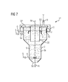
- FIG. 7 shows a fourth flotation device 1 ''' in longitudinal section. It is a columnar flotation cell as in FIG. 3 which, when operated with air for gassing the suspension S, is called a hybrid flotation cell. Same reference numerals as in the FIGS. 1 to 6 identify similar elements.
- An annular fluid distributor element 4 surrounds the insert 20 and serves to introduce fluid F in the region of the surface SO of the suspension S, the fluid F flowing radially outward in the direction of the vessel 2.
- the vertical position of the fluid distribution elements 4 is variable, which is indicated here only by double arrows.
- FIGS. 1 to 7 only examples of a flotation device according to the invention.
- the fluid distribution element, the gassing element, the foam collection device, the insert, etc. may readily be present.
- the number of inlets, outlets, fluid distribution elements, first and / or second sensors, gassing elements, control devices, positioning devices, etc. may be varied without departing from the spirit of the invention.
Landscapes
- Engineering & Computer Science (AREA)
- Life Sciences & Earth Sciences (AREA)
- Biotechnology (AREA)
- General Engineering & Computer Science (AREA)
- Physical Water Treatments (AREA)
- Paper (AREA)
- Manufacture And Refinement Of Metals (AREA)
Priority Applications (11)
| Application Number | Priority Date | Filing Date | Title |
|---|---|---|---|
| EP11158298.7A EP2500102B1 (fr) | 2011-03-15 | 2011-03-15 | Dispositif de flottation avec un élément de distribution d'un fluide pouvant générer un courant du fluide vers le collecteur en mousse |
| AU2012228575A AU2012228575A1 (en) | 2011-03-15 | 2012-03-01 | Flotation device comprising a fluid distribution element for generating a flow that is directed at the foam collecting unit |
| US14/005,204 US20140001102A1 (en) | 2011-03-15 | 2012-03-01 | Flotation device comprising a fluid distribution element for generating a flow that is directed at the foam collecting unit |
| PCT/EP2012/053491 WO2012123258A1 (fr) | 2011-03-15 | 2012-03-01 | Dispositif de flottation pourvu d'un élément répartiteur de fluide pour produire un courant dirigé vers l'appareil collecteur d'écume |
| BR112013023569A BR112013023569A2 (pt) | 2011-03-15 | 2012-03-01 | "dispositivo de flutuação, método para descarregar um produto de espuma formado em um dispositivo de flutuação e uso de um dispositivo de flutuação" |
| CN201280013047.0A CN103429352B (zh) | 2011-03-15 | 2012-03-01 | 具有用于产生指向泡沫收集装置的流动的流体分配件的浮选装置 |
| MX2013010527A MX2013010527A (es) | 2011-03-15 | 2012-03-01 | Dispositivo de flotacion con un elemento distribuidor de fluido para generar una corriente dirigida hacia el dispositivo colector de espuma. |
| CA2830205A CA2830205A1 (fr) | 2011-03-15 | 2012-03-01 | Dispositif de flottation pourvu d'un element repartiteur de fluide pour produire un courant dirige vers l'appareil collecteur d'ecume |
| RU2013145953/03A RU2013145953A (ru) | 2011-03-15 | 2012-03-01 | Флотационное устройство с элементом для распределения текучей среды для создания направляемого в пеносборное устройство потока |
| CL2013002537A CL2013002537A1 (es) | 2011-03-15 | 2013-09-03 | Dispositivo de flotacion porque comprende una carcasa con una camara de flotacion para recibir una suspension y con al menos una entrada para la suspension asi como al menos un dispositivo colector de espuma para recibir y evacuar un producto de espuma; procedimiento para evacuar un producto de espuma. |
| ZA2013/06811A ZA201306811B (en) | 2011-03-15 | 2013-09-10 | Flotation device comprising a fluid distribution element for generating a flow that is directed at the foam collecting unit |
Applications Claiming Priority (1)
| Application Number | Priority Date | Filing Date | Title |
|---|---|---|---|
| EP11158298.7A EP2500102B1 (fr) | 2011-03-15 | 2011-03-15 | Dispositif de flottation avec un élément de distribution d'un fluide pouvant générer un courant du fluide vers le collecteur en mousse |
Publications (2)
| Publication Number | Publication Date |
|---|---|
| EP2500102A1 true EP2500102A1 (fr) | 2012-09-19 |
| EP2500102B1 EP2500102B1 (fr) | 2015-11-11 |
Family
ID=44359416
Family Applications (1)
| Application Number | Title | Priority Date | Filing Date |
|---|---|---|---|
| EP11158298.7A Not-in-force EP2500102B1 (fr) | 2011-03-15 | 2011-03-15 | Dispositif de flottation avec un élément de distribution d'un fluide pouvant générer un courant du fluide vers le collecteur en mousse |
Country Status (11)
| Country | Link |
|---|---|
| US (1) | US20140001102A1 (fr) |
| EP (1) | EP2500102B1 (fr) |
| CN (1) | CN103429352B (fr) |
| AU (1) | AU2012228575A1 (fr) |
| BR (1) | BR112013023569A2 (fr) |
| CA (1) | CA2830205A1 (fr) |
| CL (1) | CL2013002537A1 (fr) |
| MX (1) | MX2013010527A (fr) |
| RU (1) | RU2013145953A (fr) |
| WO (1) | WO2012123258A1 (fr) |
| ZA (1) | ZA201306811B (fr) |
Cited By (1)
| Publication number | Priority date | Publication date | Assignee | Title |
|---|---|---|---|---|
| CN107983529A (zh) * | 2017-11-27 | 2018-05-04 | 中国地质科学院矿产综合利用研究所 | 一种从深海沉积物中提取稀土的方法 |
Families Citing this family (10)
| Publication number | Priority date | Publication date | Assignee | Title |
|---|---|---|---|---|
| CN103871307B (zh) * | 2014-03-25 | 2016-04-20 | 中国矿业大学(北京) | 浮选气泡特征提取教学实验平台 |
| RU2619624C2 (ru) * | 2015-03-13 | 2017-05-17 | Валерий Валентинович Морозов | Устройство для регулирования процесса флотации и флотоклассификации |
| BR112018072837B1 (pt) | 2016-05-09 | 2023-04-11 | Unilever Ip Holdings B.V. | Dispositivo para a purificação de efluentes compreendendo um agente espumante e método para a purificação de efluentes compreendendo um agente espumante |
| US11484815B2 (en) | 2017-11-07 | 2022-11-01 | Hewlett-Packard Development Company, L.P. | Froth coalescing |
| US11202983B2 (en) * | 2017-11-08 | 2021-12-21 | Btu International, Inc. | Devices, systems and methods for flux removal from furnace process gas |
| EP3720610B1 (fr) * | 2017-12-09 | 2025-04-23 | Opec Remediation Technologies Pty Limited | Procédé de séparation d'une substance de l'eau |
| CN109589649B (zh) * | 2018-11-20 | 2020-06-05 | 浙江大学 | 一种反气泡运输装置和方法 |
| SE543716C2 (en) * | 2019-05-17 | 2021-06-29 | Bjoerks Rostfria Ab | Apparatus, system and methods for water processing |
| CN110064522A (zh) * | 2019-05-30 | 2019-07-30 | 贵州大学 | 一种低品位磷矿自动控制浮选装置 |
| CN114011586B (zh) * | 2021-11-05 | 2024-08-09 | 赖江川 | 一种基于矿浆高度进行分离的浮游矿选机 |
Citations (11)
| Publication number | Priority date | Publication date | Assignee | Title |
|---|---|---|---|---|
| US1374447A (en) * | 1916-05-26 | 1921-04-12 | William E Greenawalt | Flotation apparatus |
| US1952727A (en) * | 1929-10-26 | 1934-03-27 | United Verde Copper Company | Froth flotation |
| DE2057195A1 (de) | 1970-11-20 | 1972-05-25 | Vni I Pi Mechanitscheskoj Abra | Vorrichtung zum Fortschaffen von Schaum aus Flotationsmaschinen |
| US4545892A (en) * | 1985-04-15 | 1985-10-08 | Alberta Energy Company Ltd. | Treatment of primary tailings and middlings from the hot water extraction process for recovering bitumen from tar sand |
| US4618430A (en) * | 1984-11-06 | 1986-10-21 | Engineering Specialties, Inc. | Process and apparatus for removing scum from a liquid surface |
| WO1993020945A1 (fr) | 1992-04-16 | 1993-10-28 | Atomaer Pty Ltd | Systeme de lavage par ecumage et d'enlevement de l'ecume |
| EP0613725A2 (fr) | 1993-02-25 | 1994-09-07 | VELO Spa | Dispositif de flottation avec moyens d'aspiration de la mousse |
| US6095336A (en) | 1997-08-29 | 2000-08-01 | Baker Hughes Incorporated | Flotation cell with radial launders for enhancing froth removal |
| US6926154B2 (en) | 2000-12-20 | 2005-08-09 | Outokumpu Oyj | Flotation machine |
| WO2006069995A1 (fr) | 2004-12-28 | 2006-07-06 | Siemens Aktiengesellschaft | Colonne de flottation pneumatique comportant un recipient de collecte de mousse |
| RU2397818C1 (ru) | 2009-06-22 | 2010-08-27 | Государственное образовательное учреждение высшего профессионального образования "Курский государственный технический университет" | Способ и устройство удаления пены из флотатора |
Family Cites Families (8)
| Publication number | Priority date | Publication date | Assignee | Title |
|---|---|---|---|---|
| US3645455A (en) * | 1969-04-04 | 1972-02-29 | Kennecott Copper Corp | Production of lubricant-grade molybdenite from byproduct concentrates of porphyry copper ores |
| CH614135A5 (en) * | 1976-11-29 | 1979-11-15 | Escher Wyss Gmbh | Flotation apparatus |
| SU700455A1 (ru) * | 1978-05-04 | 1979-11-30 | Belichenko Yurij P | Установка дл очистки сточных вод |
| CN1012945B (zh) * | 1987-03-21 | 1991-06-26 | 北京矿冶研究总院 | 一种矿物分离浮选机 |
| JP3303268B2 (ja) * | 1994-05-13 | 2002-07-15 | 財団法人埼玉県下水道公社 | スカム除去・処理設備 |
| US5687609A (en) * | 1995-10-05 | 1997-11-18 | Cyprus Amax Minerals Company | Method and apparatus for mineral flotation cell level detection |
| US8397921B2 (en) * | 2007-10-12 | 2013-03-19 | Utsunomiya Kogyo Co., Ltd. | Scum removing apparatus |
| CN201147726Y (zh) * | 2007-12-27 | 2008-11-12 | 金川集团有限公司 | 一种浮选机的推泡装置 |
-
2011
- 2011-03-15 EP EP11158298.7A patent/EP2500102B1/fr not_active Not-in-force
-
2012
- 2012-03-01 MX MX2013010527A patent/MX2013010527A/es unknown
- 2012-03-01 AU AU2012228575A patent/AU2012228575A1/en not_active Abandoned
- 2012-03-01 BR BR112013023569A patent/BR112013023569A2/pt not_active IP Right Cessation
- 2012-03-01 CN CN201280013047.0A patent/CN103429352B/zh not_active Expired - Fee Related
- 2012-03-01 CA CA2830205A patent/CA2830205A1/fr not_active Abandoned
- 2012-03-01 RU RU2013145953/03A patent/RU2013145953A/ru not_active Application Discontinuation
- 2012-03-01 US US14/005,204 patent/US20140001102A1/en not_active Abandoned
- 2012-03-01 WO PCT/EP2012/053491 patent/WO2012123258A1/fr not_active Ceased
-
2013
- 2013-09-03 CL CL2013002537A patent/CL2013002537A1/es unknown
- 2013-09-10 ZA ZA2013/06811A patent/ZA201306811B/en unknown
Patent Citations (11)
| Publication number | Priority date | Publication date | Assignee | Title |
|---|---|---|---|---|
| US1374447A (en) * | 1916-05-26 | 1921-04-12 | William E Greenawalt | Flotation apparatus |
| US1952727A (en) * | 1929-10-26 | 1934-03-27 | United Verde Copper Company | Froth flotation |
| DE2057195A1 (de) | 1970-11-20 | 1972-05-25 | Vni I Pi Mechanitscheskoj Abra | Vorrichtung zum Fortschaffen von Schaum aus Flotationsmaschinen |
| US4618430A (en) * | 1984-11-06 | 1986-10-21 | Engineering Specialties, Inc. | Process and apparatus for removing scum from a liquid surface |
| US4545892A (en) * | 1985-04-15 | 1985-10-08 | Alberta Energy Company Ltd. | Treatment of primary tailings and middlings from the hot water extraction process for recovering bitumen from tar sand |
| WO1993020945A1 (fr) | 1992-04-16 | 1993-10-28 | Atomaer Pty Ltd | Systeme de lavage par ecumage et d'enlevement de l'ecume |
| EP0613725A2 (fr) | 1993-02-25 | 1994-09-07 | VELO Spa | Dispositif de flottation avec moyens d'aspiration de la mousse |
| US6095336A (en) | 1997-08-29 | 2000-08-01 | Baker Hughes Incorporated | Flotation cell with radial launders for enhancing froth removal |
| US6926154B2 (en) | 2000-12-20 | 2005-08-09 | Outokumpu Oyj | Flotation machine |
| WO2006069995A1 (fr) | 2004-12-28 | 2006-07-06 | Siemens Aktiengesellschaft | Colonne de flottation pneumatique comportant un recipient de collecte de mousse |
| RU2397818C1 (ru) | 2009-06-22 | 2010-08-27 | Государственное образовательное учреждение высшего профессионального образования "Курский государственный технический университет" | Способ и устройство удаления пены из флотатора |
Non-Patent Citations (1)
| Title |
|---|
| DATABASE WPI Week 201065, Derwent World Patents Index; AN 2010-M31790, XP002657391 * |
Cited By (1)
| Publication number | Priority date | Publication date | Assignee | Title |
|---|---|---|---|---|
| CN107983529A (zh) * | 2017-11-27 | 2018-05-04 | 中国地质科学院矿产综合利用研究所 | 一种从深海沉积物中提取稀土的方法 |
Also Published As
| Publication number | Publication date |
|---|---|
| WO2012123258A1 (fr) | 2012-09-20 |
| CN103429352B (zh) | 2016-02-03 |
| ZA201306811B (en) | 2014-08-27 |
| AU2012228575A1 (en) | 2013-09-26 |
| CN103429352A (zh) | 2013-12-04 |
| BR112013023569A2 (pt) | 2016-12-06 |
| CL2013002537A1 (es) | 2014-03-21 |
| RU2013145953A (ru) | 2015-04-20 |
| US20140001102A1 (en) | 2014-01-02 |
| EP2500102B1 (fr) | 2015-11-11 |
| MX2013010527A (es) | 2013-10-07 |
| CA2830205A1 (fr) | 2012-09-20 |
Similar Documents
| Publication | Publication Date | Title |
|---|---|---|
| EP2500102B1 (fr) | Dispositif de flottation avec un élément de distribution d'un fluide pouvant générer un courant du fluide vers le collecteur en mousse | |
| DE3789795T2 (de) | Säulenflotationsverfahren und -vorrichtung. | |
| WO2012116848A1 (fr) | Dispositif de flottation, procédé destiné à faire fonctionner ledit dispositif de flottation ainsi que leur utilisation | |
| DE69600998T2 (de) | Verfahren und vorrichtung zur trennung von nicht löslichen teilchen aus einer flüssigkeit | |
| WO2011039190A1 (fr) | Dispositif, machine de flottation munie de ce dispositif et son procédé d'exploitation | |
| EP2266704A1 (fr) | Machine de flottation pneumatique et procédé de flottation | |
| DE2807129A1 (de) | Verfahren und vorrichtung zur herbeifuehrung von fluessig/fluessig-kontakten | |
| EP2572778B1 (fr) | Machine de flottaison avec une buse de dispersion et procédé de fonctionnementen | |
| DE69508929T2 (de) | Trennung einer suspension in ihre bestandteile | |
| EP1029975B1 (fr) | Procédé pour enlever des contaminants d'une suspension aqueuse de fibres | |
| WO2012059415A1 (fr) | Appareil de flottation et procédé de flottation | |
| EP2033713B1 (fr) | Dispositif et procédé de séparation des particules solides plongeantes et flottantes à densités différentes | |
| DE2359656C3 (de) | Vorrichtung zum Klären von feste Stoffe enthaltendem Abwasser o.dgl. Flüssigkeiten | |
| DE2747322A1 (de) | Verfahren und vorrichtung zum abtrennen von feststoffen von einer fluessigkeit | |
| DE19902148C2 (de) | Tangentiale Feststoffabtrenn-Vorrichtung | |
| DE69318822T2 (de) | Wirbelflockung von schwebenden feststoffen aus einer fluessigkeit | |
| DE60031344T2 (de) | Verfahren und Vorrichtung zur Trennung mittels pneumatischer Flotation | |
| DE102012200958A1 (de) | Flotationsverfahren | |
| DE3918213C2 (fr) | ||
| EP2377620A1 (fr) | Dispositif d'injection de gaz pour une cellule de flottation | |
| DE69621795T2 (de) | Mischen | |
| DE689083C (de) | Verfahren zur Schaumschwimmaufbereitung von Mineralien | |
| WO2013189685A1 (fr) | Dispositif pour isoler des particules magnétiques et/ou magnétisables présentes dans une suspension et son utilisation | |
| EP1001079B1 (fr) | Méthode et dispositif pour la séparation des particules d'une suspension aqueuse de fibres à papier | |
| AT504827A1 (de) | Vorrichtung zum trennen von flüssigkeit und in der flüssigkeit fein verteilten, nicht-löslichen partikeln |
Legal Events
| Date | Code | Title | Description |
|---|---|---|---|
| PUAI | Public reference made under article 153(3) epc to a published international application that has entered the european phase |
Free format text: ORIGINAL CODE: 0009012 |
|
| AK | Designated contracting states |
Kind code of ref document: A1 Designated state(s): AL AT BE BG CH CY CZ DE DK EE ES FI FR GB GR HR HU IE IS IT LI LT LU LV MC MK MT NL NO PL PT RO RS SE SI SK SM TR |
|
| AX | Request for extension of the european patent |
Extension state: BA ME |
|
| RAP1 | Party data changed (applicant data changed or rights of an application transferred) |
Owner name: SIEMENS AKTIENGESELLSCHAFT |
|
| 17P | Request for examination filed |
Effective date: 20130318 |
|
| 17Q | First examination report despatched |
Effective date: 20130705 |
|
| REG | Reference to a national code |
Ref country code: DE Ref legal event code: R079 Ref document number: 502011008314 Country of ref document: DE Free format text: PREVIOUS MAIN CLASS: B03D0001240000 Ipc: B03D0001140000 |
|
| GRAP | Despatch of communication of intention to grant a patent |
Free format text: ORIGINAL CODE: EPIDOSNIGR1 |
|
| RIC1 | Information provided on ipc code assigned before grant |
Ipc: B03D 1/02 20060101ALI20150506BHEP Ipc: B03D 1/14 20060101AFI20150506BHEP Ipc: B03D 1/24 20060101ALI20150506BHEP |
|
| INTG | Intention to grant announced |
Effective date: 20150608 |
|
| RAP1 | Party data changed (applicant data changed or rights of an application transferred) |
Owner name: PRIMETALS TECHNOLOGIES GERMANY GMBH |
|
| GRAS | Grant fee paid |
Free format text: ORIGINAL CODE: EPIDOSNIGR3 |
|
| GRAA | (expected) grant |
Free format text: ORIGINAL CODE: 0009210 |
|
| AK | Designated contracting states |
Kind code of ref document: B1 Designated state(s): AL AT BE BG CH CY CZ DE DK EE ES FI FR GB GR HR HU IE IS IT LI LT LU LV MC MK MT NL NO PL PT RO RS SE SI SK SM TR |
|
| REG | Reference to a national code |
Ref country code: GB Ref legal event code: FG4D Free format text: NOT ENGLISH |
|
| REG | Reference to a national code |
Ref country code: CH Ref legal event code: EP |
|
| REG | Reference to a national code |
Ref country code: IE Ref legal event code: FG4D Free format text: LANGUAGE OF EP DOCUMENT: GERMAN |
|
| REG | Reference to a national code |
Ref country code: AT Ref legal event code: REF Ref document number: 760181 Country of ref document: AT Kind code of ref document: T Effective date: 20151215 |
|
| REG | Reference to a national code |
Ref country code: DE Ref legal event code: R096 Ref document number: 502011008314 Country of ref document: DE |
|
| REG | Reference to a national code |
Ref country code: LT Ref legal event code: MG4D |
|
| REG | Reference to a national code |
Ref country code: NL Ref legal event code: MP Effective date: 20160211 |
|
| PG25 | Lapsed in a contracting state [announced via postgrant information from national office to epo] |
Ref country code: LT Free format text: LAPSE BECAUSE OF FAILURE TO SUBMIT A TRANSLATION OF THE DESCRIPTION OR TO PAY THE FEE WITHIN THE PRESCRIBED TIME-LIMIT Effective date: 20151111 Ref country code: ES Free format text: LAPSE BECAUSE OF FAILURE TO SUBMIT A TRANSLATION OF THE DESCRIPTION OR TO PAY THE FEE WITHIN THE PRESCRIBED TIME-LIMIT Effective date: 20151111 Ref country code: NO Free format text: LAPSE BECAUSE OF FAILURE TO SUBMIT A TRANSLATION OF THE DESCRIPTION OR TO PAY THE FEE WITHIN THE PRESCRIBED TIME-LIMIT Effective date: 20160211 Ref country code: IT Free format text: LAPSE BECAUSE OF FAILURE TO SUBMIT A TRANSLATION OF THE DESCRIPTION OR TO PAY THE FEE WITHIN THE PRESCRIBED TIME-LIMIT Effective date: 20151111 Ref country code: HR Free format text: LAPSE BECAUSE OF FAILURE TO SUBMIT A TRANSLATION OF THE DESCRIPTION OR TO PAY THE FEE WITHIN THE PRESCRIBED TIME-LIMIT Effective date: 20151111 Ref country code: NL Free format text: LAPSE BECAUSE OF FAILURE TO SUBMIT A TRANSLATION OF THE DESCRIPTION OR TO PAY THE FEE WITHIN THE PRESCRIBED TIME-LIMIT Effective date: 20151111 Ref country code: IS Free format text: LAPSE BECAUSE OF FAILURE TO SUBMIT A TRANSLATION OF THE DESCRIPTION OR TO PAY THE FEE WITHIN THE PRESCRIBED TIME-LIMIT Effective date: 20160311 |
|
| PGFP | Annual fee paid to national office [announced via postgrant information from national office to epo] |
Ref country code: DE Payment date: 20160321 Year of fee payment: 6 |
|
| PG25 | Lapsed in a contracting state [announced via postgrant information from national office to epo] |
Ref country code: GR Free format text: LAPSE BECAUSE OF FAILURE TO SUBMIT A TRANSLATION OF THE DESCRIPTION OR TO PAY THE FEE WITHIN THE PRESCRIBED TIME-LIMIT Effective date: 20160212 Ref country code: LV Free format text: LAPSE BECAUSE OF FAILURE TO SUBMIT A TRANSLATION OF THE DESCRIPTION OR TO PAY THE FEE WITHIN THE PRESCRIBED TIME-LIMIT Effective date: 20151111 Ref country code: PL Free format text: LAPSE BECAUSE OF FAILURE TO SUBMIT A TRANSLATION OF THE DESCRIPTION OR TO PAY THE FEE WITHIN THE PRESCRIBED TIME-LIMIT Effective date: 20151111 Ref country code: SE Free format text: LAPSE BECAUSE OF FAILURE TO SUBMIT A TRANSLATION OF THE DESCRIPTION OR TO PAY THE FEE WITHIN THE PRESCRIBED TIME-LIMIT Effective date: 20151111 Ref country code: RS Free format text: LAPSE BECAUSE OF FAILURE TO SUBMIT A TRANSLATION OF THE DESCRIPTION OR TO PAY THE FEE WITHIN THE PRESCRIBED TIME-LIMIT Effective date: 20151111 Ref country code: PT Free format text: LAPSE BECAUSE OF FAILURE TO SUBMIT A TRANSLATION OF THE DESCRIPTION OR TO PAY THE FEE WITHIN THE PRESCRIBED TIME-LIMIT Effective date: 20160311 |
|
| PGFP | Annual fee paid to national office [announced via postgrant information from national office to epo] |
Ref country code: FI Payment date: 20160311 Year of fee payment: 6 |
|
| PG25 | Lapsed in a contracting state [announced via postgrant information from national office to epo] |
Ref country code: CZ Free format text: LAPSE BECAUSE OF FAILURE TO SUBMIT A TRANSLATION OF THE DESCRIPTION OR TO PAY THE FEE WITHIN THE PRESCRIBED TIME-LIMIT Effective date: 20151111 |
|
| REG | Reference to a national code |
Ref country code: DE Ref legal event code: R097 Ref document number: 502011008314 Country of ref document: DE |
|
| PG25 | Lapsed in a contracting state [announced via postgrant information from national office to epo] |
Ref country code: SK Free format text: LAPSE BECAUSE OF FAILURE TO SUBMIT A TRANSLATION OF THE DESCRIPTION OR TO PAY THE FEE WITHIN THE PRESCRIBED TIME-LIMIT Effective date: 20151111 Ref country code: BE Free format text: LAPSE BECAUSE OF NON-PAYMENT OF DUE FEES Effective date: 20160331 Ref country code: EE Free format text: LAPSE BECAUSE OF FAILURE TO SUBMIT A TRANSLATION OF THE DESCRIPTION OR TO PAY THE FEE WITHIN THE PRESCRIBED TIME-LIMIT Effective date: 20151111 Ref country code: DK Free format text: LAPSE BECAUSE OF FAILURE TO SUBMIT A TRANSLATION OF THE DESCRIPTION OR TO PAY THE FEE WITHIN THE PRESCRIBED TIME-LIMIT Effective date: 20151111 Ref country code: RO Free format text: LAPSE BECAUSE OF FAILURE TO SUBMIT A TRANSLATION OF THE DESCRIPTION OR TO PAY THE FEE WITHIN THE PRESCRIBED TIME-LIMIT Effective date: 20151111 Ref country code: SM Free format text: LAPSE BECAUSE OF FAILURE TO SUBMIT A TRANSLATION OF THE DESCRIPTION OR TO PAY THE FEE WITHIN THE PRESCRIBED TIME-LIMIT Effective date: 20151111 |
|
| PLBE | No opposition filed within time limit |
Free format text: ORIGINAL CODE: 0009261 |
|
| STAA | Information on the status of an ep patent application or granted ep patent |
Free format text: STATUS: NO OPPOSITION FILED WITHIN TIME LIMIT |
|
| 26N | No opposition filed |
Effective date: 20160812 |
|
| PG25 | Lapsed in a contracting state [announced via postgrant information from national office to epo] |
Ref country code: LU Free format text: LAPSE BECAUSE OF FAILURE TO SUBMIT A TRANSLATION OF THE DESCRIPTION OR TO PAY THE FEE WITHIN THE PRESCRIBED TIME-LIMIT Effective date: 20160315 Ref country code: MC Free format text: LAPSE BECAUSE OF FAILURE TO SUBMIT A TRANSLATION OF THE DESCRIPTION OR TO PAY THE FEE WITHIN THE PRESCRIBED TIME-LIMIT Effective date: 20151111 |
|
| REG | Reference to a national code |
Ref country code: CH Ref legal event code: PL |
|
| GBPC | Gb: european patent ceased through non-payment of renewal fee |
Effective date: 20160315 |
|
| PG25 | Lapsed in a contracting state [announced via postgrant information from national office to epo] |
Ref country code: SI Free format text: LAPSE BECAUSE OF FAILURE TO SUBMIT A TRANSLATION OF THE DESCRIPTION OR TO PAY THE FEE WITHIN THE PRESCRIBED TIME-LIMIT Effective date: 20151111 |
|
| REG | Reference to a national code |
Ref country code: IE Ref legal event code: MM4A |
|
| REG | Reference to a national code |
Ref country code: FR Ref legal event code: ST Effective date: 20161130 |
|
| PG25 | Lapsed in a contracting state [announced via postgrant information from national office to epo] |
Ref country code: LI Free format text: LAPSE BECAUSE OF NON-PAYMENT OF DUE FEES Effective date: 20160331 Ref country code: CH Free format text: LAPSE BECAUSE OF NON-PAYMENT OF DUE FEES Effective date: 20160331 Ref country code: IE Free format text: LAPSE BECAUSE OF NON-PAYMENT OF DUE FEES Effective date: 20160315 Ref country code: GB Free format text: LAPSE BECAUSE OF NON-PAYMENT OF DUE FEES Effective date: 20160315 Ref country code: FR Free format text: LAPSE BECAUSE OF NON-PAYMENT OF DUE FEES Effective date: 20160331 |
|
| REG | Reference to a national code |
Ref country code: AT Ref legal event code: MM01 Ref document number: 760181 Country of ref document: AT Kind code of ref document: T Effective date: 20160315 |
|
| PG25 | Lapsed in a contracting state [announced via postgrant information from national office to epo] |
Ref country code: MT Free format text: LAPSE BECAUSE OF FAILURE TO SUBMIT A TRANSLATION OF THE DESCRIPTION OR TO PAY THE FEE WITHIN THE PRESCRIBED TIME-LIMIT Effective date: 20151111 Ref country code: AT Free format text: LAPSE BECAUSE OF NON-PAYMENT OF DUE FEES Effective date: 20160315 |
|
| REG | Reference to a national code |
Ref country code: DE Ref legal event code: R119 Ref document number: 502011008314 Country of ref document: DE |
|
| PG25 | Lapsed in a contracting state [announced via postgrant information from national office to epo] |
Ref country code: FI Free format text: LAPSE BECAUSE OF NON-PAYMENT OF DUE FEES Effective date: 20170315 |
|
| PG25 | Lapsed in a contracting state [announced via postgrant information from national office to epo] |
Ref country code: DE Free format text: LAPSE BECAUSE OF NON-PAYMENT OF DUE FEES Effective date: 20171003 |
|
| PG25 | Lapsed in a contracting state [announced via postgrant information from national office to epo] |
Ref country code: CY Free format text: LAPSE BECAUSE OF FAILURE TO SUBMIT A TRANSLATION OF THE DESCRIPTION OR TO PAY THE FEE WITHIN THE PRESCRIBED TIME-LIMIT Effective date: 20151111 Ref country code: HU Free format text: LAPSE BECAUSE OF FAILURE TO SUBMIT A TRANSLATION OF THE DESCRIPTION OR TO PAY THE FEE WITHIN THE PRESCRIBED TIME-LIMIT; INVALID AB INITIO Effective date: 20110315 |
|
| PG25 | Lapsed in a contracting state [announced via postgrant information from national office to epo] |
Ref country code: MK Free format text: LAPSE BECAUSE OF FAILURE TO SUBMIT A TRANSLATION OF THE DESCRIPTION OR TO PAY THE FEE WITHIN THE PRESCRIBED TIME-LIMIT Effective date: 20151111 Ref country code: TR Free format text: LAPSE BECAUSE OF FAILURE TO SUBMIT A TRANSLATION OF THE DESCRIPTION OR TO PAY THE FEE WITHIN THE PRESCRIBED TIME-LIMIT Effective date: 20151111 |
|
| PG25 | Lapsed in a contracting state [announced via postgrant information from national office to epo] |
Ref country code: BG Free format text: LAPSE BECAUSE OF FAILURE TO SUBMIT A TRANSLATION OF THE DESCRIPTION OR TO PAY THE FEE WITHIN THE PRESCRIBED TIME-LIMIT Effective date: 20151111 |
|
| PG25 | Lapsed in a contracting state [announced via postgrant information from national office to epo] |
Ref country code: AL Free format text: LAPSE BECAUSE OF FAILURE TO SUBMIT A TRANSLATION OF THE DESCRIPTION OR TO PAY THE FEE WITHIN THE PRESCRIBED TIME-LIMIT Effective date: 20151111 |