EP2501522B1 - Vorrichtung mit einer schleuderradvorrichtung - Google Patents
Vorrichtung mit einer schleuderradvorrichtung Download PDFInfo
- Publication number
- EP2501522B1 EP2501522B1 EP09851351.8A EP09851351A EP2501522B1 EP 2501522 B1 EP2501522 B1 EP 2501522B1 EP 09851351 A EP09851351 A EP 09851351A EP 2501522 B1 EP2501522 B1 EP 2501522B1
- Authority
- EP
- European Patent Office
- Prior art keywords
- throwing
- locking member
- runnerhead
- vane
- mounting
- Prior art date
- Legal status (The legal status is an assumption and is not a legal conclusion. Google has not performed a legal analysis and makes no representation as to the accuracy of the status listed.)
- Active
Links
Images


Classifications
-
- B—PERFORMING OPERATIONS; TRANSPORTING
- B24—GRINDING; POLISHING
- B24C—ABRASIVE OR RELATED BLASTING WITH PARTICULATE MATERIAL
- B24C5/00—Devices or accessories for generating abrasive blasts
- B24C5/06—Impeller wheels; Rotor blades therefor
- B24C5/062—Rotor blades or vanes; Locking means therefor
Definitions
- the present invention relates generally to new and useful improvements in a rotatable abrading device of the type commonly referred to as centrifugal blasting machines, and more particularly to the throwing wheels and blade assemblies that are used in such machines
- Abrasive blasting machines having a wheel or rotor assembly provided with a plurality of abrasive throwing blades or vanes arranged radially about the face of the rotor are well known.
- a stream of abrasive particulate material is fed into the path of the rotating wheel from an impeller secured to the rotor.
- the blades are adapted to receive and throw the abrasive from the periphery of the rotor at an appropriate discharge point in the machine casing at a blasting velocity to strip or clean metal castings or the like.
- the throwing vanes due to the nature of their use are subject to excessive wear and are, therefore, removably mounted on a runnerhead portion of the wheel assembly for replacement as needed.
- runnerhead assemblies There are two basic styles of runnerhead assemblies, a single-sided runnerhead and double-sided runnerhead.
- the use of a single-sided runnerhead is advantageous to reduce the "overhung load" on the shaft of the motor or spindle.
- the double-sided runnerhead may protect the internal liners on the front of the wheel housing. Many different methods of fixing the blades to a runnerhead assembly have been employed.
- the present invention provides an apparatus according to claim 1.
- Throwing wheel 100 may include a central hub or rotor 12 to which may be affixed a runnerhead 13 having a common axis of rotation 31 therewith.
- a plurality of throwing blades 14 (also referred to as blades or vanes) may be perpendicularly mounted on the face of runnerhead 13 and may extend substantially radially from the axis of rotation 31 of rotor 12.
- An innermost inlet end 16 of each throwing blade 14 may be spaced a distance from the axis of rotation 31 for receiving particulate abrasive material from an impeller 23.
- Impeller 23 may be disposed on the hub 12 between the inlet ends 16 of throwing blades 14 for feeding the abrasive particles which are received from a fixed spout 20 to throwing blades 14 in a usual manner.
- Each throwing blade 14 may have two side edges 30, 29, a front throwing face 15 and a rear throwing face 9, an inlet end 16 and an outlet end 17.
- the impeller case 21 may comprise an open-ended flange 22 connected to the machine casing and open to the spout 20.
- An impeller 23 may be disposed within case 21 and is rotatably affixed to hub 12. Impeller 23 may be provided with openings 24 for discharging abrasive received from spout 20 outwardly of case 21 through a discharge opening 25 therein upon rotation of wheel 100.
- abrasives may be fed to the inlet ends 16 of throwing blades 14 as the throwing blades 14 rotate past the opening 25.
- the abrasive may then be moved along the front throwing face 15 of the blade from the inlet end 16 to the outlet end 17 for discharge therefrom at a selected blasting velocity.
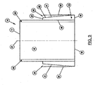
- FIG. 2 depicts a perspective cross-sectional view of a double-sided runnerhead assembly 130, according to an exemplary embodiment of the present invention.
- the runnerhead assembly 130 may include a first runnerhead 13A, or first mounting element, and a second runnerhead 13B, or second mounting element.
- the runnerheads 13A, 13B may be arranged substantially parallel to one another and may be spaced apart from one another along a central axis of rotation 31.
- a plurality of throwing blades 14 may be mounted substantially perpendicular to the inner faces of runnerheads 13A and 13B and may extend substantially radially from the axis of rotation 31 of rotor 12.
- each throwing blade 14 may be spaced a distance from the axis of rotation 31 to receive particulate abrasive material from an impeller 23.
- the use of a double-sided runnerhead may be advantageous to reduce the "overhung load" on the shaft of the motor or spindle 32.
- a throwing blade 14 of novel configuration may be provided for quick and easy removal from the runnerhead assembly 130 in the most efficient way possible with a minimum of complex removable parts. Referring to FIGs. 3-5 , there is shown in greater detail the throwing blades 14 according to embodiments of the present invention.
- FIG. 3 depicts a front elevational view of a throwing blade 14 with two locking members 40, according to an exemplary embodiment of the present invention.
- the throwing blade 14 includes an inlet end 16, an outlet end 17, and a particle throwing portion extending between the inlet and outlet ends 16, 17.
- the particle throwing portion includes a front throwing face 15, a rear throwing face 9 (see FIG. 4 ) and two side edges 29, 30.
- Each of the side edges 29, 30 may extend substantially parallel to one another between the inlet end 16 and the outlet end 17 on opposite sides at the vane.
- Each side edge 29, 30 may include a locking member 40 that may be detachably coupled to a mounting element 50 (see FIG. 6 ) of a runnerhead 13A, B at connection 48.
- Each locking member 40 may include a top end 46, a bottom end 47, a front surface 43, and two front-side surfaces 42, 44 (see FIG. 5 ).
- the front surface 43 is arranged between the top end 46 and the bottom end 47 and extends at an angle towards the axis of rotation 31 (See FIG. 1 ) opposite the connection 48 between the locking member 40 and the throwing face 9.
- the front-side surfaces 42, 44 are also each arranged between the top end 46 and the bottom end 47.
- the front-side surfaces 42, 44 are each further positioned between the front surface 43 and the connection 48 between the locking member 40 and the throwing face 9.
- Each locking member 40 may be tapered at an angle 41 in a first plane 80.
- the first plane 80 may be substantially parallel to each side edge of the vane 29, 30 and/or the central axis 81 of the throwing blade 14.
- the front surface 43 may be tapered from the bottom end 47 to the top end 46 in a direction substantially perpendicular to the connection 48 between the locking member 40 and the side edges 29, 30 of the throwing blade 14.
- the front surface 43 may be tapered along the entire length of the locking member 40.
- the front surface 43 may be tapered at an angle between approximately three- to seven-degrees.
- the locking member 40 may either be made from the same or different material as the vane 14.
- FIG. 4 depicts a top view of the throwing blade 14 with two locking members 40 of FIG. 3 .
- Each side edge 29, 30, as shown in FIG. 3 may be a flange coupled to each side of the front and rear throwing faces 15, 9.
- the locking members 40 may protrude out from the side edges 29, 30 of the throwing blade 14 at connection 48 towards the mounting element.
- the locking members 40 are positioned along the side edges 29, 30 near the inlet end 16 of the throwing blade 14. However, other positions for the locking members 40 may alternatively be used.
- FIG. 5 depicts a side view of the throwing blade 14 with two locking members 40 of FIG. 3 .
- each locking member 40 located on side edges 29, 30 may be tapered at an angle 45.
- each front-side surface 42, 44 may be tapered from the bottom end 47 to the top end 46 in a direction towards a center axis 83 of the locking member 40 and/or side edge 29, 30 of the throwing blade 14.
- the top edge 46 may be rounded or arched.
- each front-side surface 42, 44 may be tapered along the entire length of locking member 40. However, in some embodiments the front-side surface 42, 44 may not touch along the entire surface of the mounting recess.
- the front-side surfaces 42, 44 may be tapered at an angle 45 between approximately three- and seven-degrees.
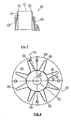
- FIG. 6 depicts a side view of a runnerhead 13A with mounting recesses 50 according to an exemplary embodiment of the present invention.
- the runnerhead 13A, or mounting element may define a mounting face 60 having a central bore 61 and a plurality of radially extending mounting recesses 50.
- Each mounting recess 50 may be adapted to detachably receive a locking member 40 of a throwing blade 14.
- Each mounting recess may include a first end 56, a second end 57, a bottom recessed portion 53 and two bottom-side recessed portions 52, 54.
- the mounting recesses 50 may be positioned on the mounting face 60 radially at a distance from the central bore 61.
- each mounting recess 50 may be tapered at a first angle in a first plane and at a second angle 55 in a second plane 92 that is perpendicular to the first plane.
- the first plane may correspond to the first plane 80 of the locking member 40 coupled to the throwing blade 14.
- the bottom recessed portion 53 may be tapered at an angle from the second end 57 to the first end 56 along the axis of rotation 31 (see FIG. 1 ), so that the bottom recessed portion 53 is recessed deeper into the mounting face at the second end 57 than at the first end 56.
- the bottom-side recessed portions 52, 54 may be tapered at an angle 55 from the second end 57 to the first end 56 in a direction towards a center axis 93 of the mounting recess 50.
- the first plane may be substantially parallel to the axis of rotation and the second plane 92 may be substantially perpendicular to the first plane.
- FIG. 7 depicts a perspective view of the throwing blades 14 locked into the mounting recesses 50 of the runnerhead, according to an exemplary embodiment of the present invention.
- the side edges 29, 30 of the throwing blade 14 may define a width smaller than a pre-determined distance between the first and second runnerheads 13A, 13B, or mounting elements, of the mounting assembly 130 so that when coupled to the runnerheads 13A, 13B a gap 70 may be present on both sides of the vane.
- the gap 70 may be sized such that the largest abrasive used by the throwing wheel assembly 100 cannot become lodged in the gap.
- FIG. 8 depicts an alternative front perspective view of the throwing blades 14 locked into the mounting recesses 50 of the runnerhead 13A, 13B according to an exemplary embodiment of the present invention.
Landscapes
- Engineering & Computer Science (AREA)
- Mechanical Engineering (AREA)
- Structures Of Non-Positive Displacement Pumps (AREA)
- Crushing And Pulverization Processes (AREA)
- Disintegrating Or Milling (AREA)
- Polishing Bodies And Polishing Tools (AREA)
Claims (4)
- Vorrichtung (130), umfassend:eine Schleuderradvorrichtung, welche ein erstes Montageelement und ein zweites Montageelement umfasst, wobei jedes der Montageelemente zur lösbaren Aufnahme eines Verriegelungsglieds (40) einer Radschaufel ausgebildet ist;welche Radschaufel ein erstes Ende (16);ein zweites Ende (17); undeinen Partikelschleuderteil umfasst, der sich zwischen dem ersten und zweiten Ende erstreckt und eine erste Schleuderseite (15), eine zweite Schleuderseite (9) sowie zwei Seitenkanten (29, 30) enthält,wobei jede der Seitenkanten sich im Wesentlichen parallel zueinander erstreckt und ein Verriegelungsglied (40) enthält, welches zum lösbaren Verbinden mit einem Montageelement (50) der Schleuderradvorrichtung ausgebildet ist,dadurch gekennzeichnet, dass jedes Verriegelungsglied (40) eine vom ersten Ende zum zweiten Ende hin sich erstreckende erste Oberfläche, wobei die erste Oberfläche entlang einer ersten Richtung in einem ersten Winkel (41) sich verjüngt, und eine vom ersten Ende zum zweiten Ende hin sich erstreckende zweite Oberfläche, wobei die zweite Oberfläche entlang der ersten Richtung in einem zweiten Winkel (45) sich verjüngt, enthält wobei die erste Richtung sich vom ersten Ende (16) zum zweiten Ende (17) der Radschaufel hin erstreckt,wobei die Seitenkanten eine Breite definieren, die kleiner als ein vorgegebener Abstand zwischen dem ersten und zweiten Montageelement der Schleuderradvorrichtung ist, so dass beim Verbinden mit den Montageelementen ein Spalt (70) beidseitig der Radschaufel vorhanden ist.
- Vorrichtung nach Anspruch 1, wobei das Verriegelungsglied (40) aus Seitenkanten (29, 30) der Radschaufel hervorsteht.
- Vorrichtung nach Anspruch 1, wobei das Verriegelungsglied (40) umfasst: eine Stirnfläche (43), welche die erste Oberfläche ist, und zwei Stirnseitenflächen (42, 44), welche Stirnseitenflächen zwischen der Stirnfläche (43) und den jeweiligen der ersten Schleuderseite und der zweiten Schleuderseite angeordnet sind.
- Vorrichtung nach Anspruch 3, wobei die Stirnseitenflächen (42, 44) zweite im zweiten Winkel (45) sich verjüngende Oberflächen sind.
Applications Claiming Priority (2)
| Application Number | Priority Date | Filing Date | Title |
|---|---|---|---|
| US12/619,452 US8550881B2 (en) | 2009-11-16 | 2009-11-16 | Vane, mounting assembly and throwing wheel apparatus having a locking member tapered in two planes |
| PCT/US2009/069271 WO2011059464A1 (en) | 2009-11-16 | 2009-12-22 | A vane, mounting assembly and throwing wheel apparatus having a locking member tapered in two planes |
Publications (3)
| Publication Number | Publication Date |
|---|---|
| EP2501522A1 EP2501522A1 (de) | 2012-09-26 |
| EP2501522A4 EP2501522A4 (de) | 2014-11-26 |
| EP2501522B1 true EP2501522B1 (de) | 2015-12-16 |
Family
ID=43991893
Family Applications (1)
| Application Number | Title | Priority Date | Filing Date |
|---|---|---|---|
| EP09851351.8A Active EP2501522B1 (de) | 2009-11-16 | 2009-12-22 | Vorrichtung mit einer schleuderradvorrichtung |
Country Status (7)
| Country | Link |
|---|---|
| US (1) | US8550881B2 (de) |
| EP (1) | EP2501522B1 (de) |
| CN (1) | CN102348534B (de) |
| CA (1) | CA2759875C (de) |
| ES (1) | ES2563642T3 (de) |
| MX (1) | MX2011011213A (de) |
| WO (1) | WO2011059464A1 (de) |
Families Citing this family (16)
| Publication number | Priority date | Publication date | Assignee | Title |
|---|---|---|---|---|
| US8926406B2 (en) * | 2010-01-21 | 2015-01-06 | Accelabrator Technologies Llc | Surface applied abrasive cleaning apparatus and method |
| KR102197338B1 (ko) * | 2013-10-31 | 2021-01-04 | 신토고교 가부시키가이샤 | 원심 투사기 및 블레이드 |
| US9440330B2 (en) * | 2014-01-07 | 2016-09-13 | Astech Alloy Steel Technologies, Inc. | Shot blast cleaning wheel blade and blade and wheel combination |
| CN103878699A (zh) * | 2014-04-04 | 2014-06-25 | 北京理工大学 | 一种柔性喷射抛光装置 |
| JP1512010S (de) * | 2014-06-18 | 2017-11-13 | ||
| US9488548B2 (en) | 2014-11-10 | 2016-11-08 | Robert Bosch Gmbh | Apparatus and method for testing an airbag control unit |
| CN105127906B (zh) * | 2015-08-25 | 2019-02-12 | 杨华杰 | 一种用于管壁表面处理的立式抛丸处理机系统及抛丸处理方法 |
| CN105127907B (zh) * | 2015-08-25 | 2018-02-16 | 杨华杰 | 一种立式抛丸处理装置及抛丸处理方法 |
| CN105643476B (zh) * | 2016-03-17 | 2019-02-19 | 大丰市鑫海机电设备有限公司 | 高效抛丸器 |
| PL424642A1 (pl) * | 2018-02-21 | 2019-08-26 | Przedsiębiorstwo Projektowo-Produkcyjne Ideapro Spółka Z Ograniczoną Odpowiedzialnością | Sposób mocowania łopatek rzutowych w kole rzutowym |
| CN109664203B (zh) * | 2019-01-30 | 2020-05-26 | 昆山亚比斯环保包装材料有限公司 | 一种叶片、叶轮结构及投射设备 |
| CN110328622A (zh) * | 2019-07-08 | 2019-10-15 | 昆山亚比斯环保包装材料有限公司 | 一种叶片、叶轮结构及叶轮紧扣式喷击机械 |
| TWI758637B (zh) * | 2019-09-11 | 2022-03-21 | 亞比斯創新科技股份有限公司 | 葉輪結構及投射設備 |
| TWI709460B (zh) * | 2019-09-12 | 2020-11-11 | 亞比斯包材工場股份有限公司 | 噴擊機台及其葉輪設備 |
| CN111644988A (zh) * | 2020-06-30 | 2020-09-11 | 盐城迪尔特抛丸设备有限公司 | 一种抛丸器及其应用方法 |
| US11826882B1 (en) * | 2022-12-27 | 2023-11-28 | Paul Enegren | Blast wheel and quick-connect blade assembly |
Family Cites Families (79)
| Publication number | Priority date | Publication date | Assignee | Title |
|---|---|---|---|---|
| US700224A (en) | 1901-03-12 | 1902-05-20 | John D Mcrae | Centrifugal pump. |
| US1286865A (en) * | 1918-06-28 | 1918-12-03 | Sprout Waldron & Company | Middlings mill or grinder. |
| GB449253A (en) | 1934-02-23 | 1936-06-18 | American Foundry Equip Co | Improvements in or relating to abrasive throwing wheels |
| US2590576A (en) * | 1934-05-17 | 1952-03-25 | Pangborn Corp | Abrading apparatus |
| GB464608A (en) | 1935-06-21 | 1937-04-21 | American Foundry Equip Co | Improvements in abrasive throwing apparatus |
| GB510681A (en) | 1937-02-04 | 1939-08-04 | Ame Ets A Sisson Lehmann | Improvements in and relating to centrifugally spraying matter suspended in fluids |
| GB533051A (en) | 1938-10-07 | 1941-02-05 | American Foundry Equip Co | Improvements relating to centrifugal abrasive projecting machines |
| GB527619A (en) | 1939-06-13 | 1940-10-11 | William Warren Triggs | Abrading apparatus |
| GB532480A (en) | 1939-08-31 | 1941-01-24 | Chester Ellsworth Unger | Improvements relating to abrasive projecting machines |
| GB545650A (en) | 1941-04-04 | 1942-06-05 | Tilghman S Patent Sand Blast C | Improvements relating to centrifugal sand blasting machines |
| GB654420A (en) | 1942-06-12 | 1951-06-20 | Pangborn Corp | Abrading apparatus |
| GB750432A (en) | 1952-09-23 | 1956-06-13 | Pangborn Corp | Centrifugal blasting apparatus |
| GB729012A (en) | 1952-09-23 | 1955-04-27 | Pangborn Corp | Improvements in or relating to the chill-casting of hollow metal articles |
| US2819562A (en) * | 1956-05-07 | 1958-01-14 | Wheelabrator Corp | Centrifugal blasting wheel and blades for use in same |
| GB821869A (en) | 1956-05-07 | 1959-10-14 | Wheelabrator Corp | Centrifugal blasting wheel |
| GB830042A (en) | 1957-01-16 | 1960-03-09 | John Arthur Frank Kinsman | Improvements in or relating to centrifugal machines |
| GB912242A (en) | 1958-04-03 | 1962-12-05 | William Robertson Macmillan | Improvements in or relating to blade retaining means in shot blast impeller wheels |
| US3197920A (en) * | 1962-05-18 | 1965-08-03 | Pangborn Corp | Throwing wheel and parts therefor |
| GB1003441A (en) | 1963-04-18 | 1965-09-02 | Spencer & Halstead Ltd | Blades for the impellers of blast-cleaning machines |
| US3241266A (en) * | 1963-07-10 | 1966-03-22 | Pangborn Corp | Abrasive particle throwing wheel assembly |
| US3287858A (en) * | 1964-07-13 | 1966-11-29 | Pangborn Corp | Abrasive blasting wheel assembly |
| GB1041459A (en) | 1964-10-05 | 1966-09-07 | Pangborn Corp | Throwing wheel vane |
| US3368308A (en) * | 1964-11-03 | 1968-02-13 | Pangborn Corp | Centrifugal blasting apparatus |
| US3513597A (en) * | 1965-02-01 | 1970-05-26 | Wheelabrator Corp | Locking blade for centrifugal blasting wheel |
| GB1114403A (en) | 1965-06-29 | 1968-05-22 | Pangborn Corp | Improvements in abrasive blasting wheels and throwing vanes therefor |
| US3694963A (en) * | 1970-03-25 | 1972-10-03 | Wheelabrator Frye Inc | Centrifugal blasting wheel |
| CH507780A (de) * | 1970-05-06 | 1971-05-31 | Fischer Ag Georg | Schleuderrad zum Schleudern von Schleudergut |
| GB1320641A (en) * | 1971-03-29 | 1973-06-20 | Vacu Blast Ltd | Impelling wheel for particulate material |
| US3785105A (en) * | 1972-04-05 | 1974-01-15 | Wheelabrator Frye Inc | Centrifugal blasting wheel |
| US3872624A (en) * | 1973-10-29 | 1975-03-25 | Carborundum Co | Curved vane for throwing wheels |
| US3867791A (en) * | 1974-05-13 | 1975-02-25 | James R Goff | Abrasive blasting machine |
| US3897014A (en) * | 1974-05-13 | 1975-07-29 | Ingersoll Rand Co | Material disintegrating-and-blowing apparatus |
| US4034516A (en) * | 1974-05-17 | 1977-07-12 | Riichi Maeda | Centrifugal blasting apparatus |
| US3945150A (en) * | 1975-01-20 | 1976-03-23 | The Carborundum Company | Runnerhead for a throwing wheel |
| GB1500092A (en) * | 1975-10-24 | 1978-02-08 | Tilghman Wheelabrator Ltd | Blast impellor wheels |
| US4164104A (en) * | 1977-10-28 | 1979-08-14 | The Carborundum Company | Apparatus and method for obtaining a shortened blast pattern with a centrifugal throwing wheel |
| CH623769A5 (de) * | 1977-11-17 | 1981-06-30 | Fischer Ag Georg | |
| US4176502A (en) * | 1978-02-15 | 1979-12-04 | Wheelabrator-Frye Inc. | Spacerless blasting wheel and blade locking arrangement therefor |
| US4174814A (en) * | 1978-04-03 | 1979-11-20 | Spokane Crusher Manufacturing Co. | Impeller shoe for centrifugal impact rock crushing machine |
| US4249350A (en) * | 1979-01-15 | 1981-02-10 | Goff James R | Abrasive throwing wheel and improved blade assembly |
| US4480413A (en) * | 1979-09-24 | 1984-11-06 | Wheelabrator-Frye Inc. | Bladed centrifugal blasting wheel |
| US4329819A (en) * | 1980-04-18 | 1982-05-18 | Ervin Industries, Inc. | Centrifugal blasting apparatus |
| US4680899A (en) * | 1981-01-06 | 1987-07-21 | Pangborn Corporation | Portable abrasive throwing wheel device |
| US4395851A (en) * | 1981-02-03 | 1983-08-02 | Watts W David | Centrifugal abrasive blasting machine |
| US4509300A (en) * | 1981-03-18 | 1985-04-09 | Kennecott Corporation | Vane retention apparatus for abrasive blasting machine |
| US4447993A (en) * | 1982-04-16 | 1984-05-15 | Laido Donald A | Alignment means for centrifugal blasting wheel |
| JPS5947163A (ja) | 1982-09-10 | 1984-03-16 | Kyocera Corp | サンドブラスト用回転羽根 |
| GB8332348D0 (en) * | 1983-12-03 | 1984-01-11 | Massey A | Machine part |
| US4941297A (en) * | 1983-06-30 | 1990-07-17 | Pangborn Corporation | Flared vane for abrasive blasting wheel |
| FI81512C (fi) * | 1983-11-29 | 1990-11-12 | Hofmeyr Van Huyssteen Jan H | Loephjul foer en sandblaestringsanordning. |
| US4627197A (en) * | 1983-12-08 | 1986-12-09 | Air Products And Chemicals, Inc. | Process control for cryogenic decoating |
| GB8410555D0 (en) | 1984-04-25 | 1984-05-31 | Autoblast Ltd | Abrasive throwing machine |
| GB8415261D0 (en) | 1984-06-15 | 1984-07-18 | Tilghman Wheelabrator Ltd | Shot blasting machinery |
| US4739937A (en) * | 1985-08-19 | 1988-04-26 | Pangborn Corporation | Apparatus for conditioning granular material |
| US4646483A (en) * | 1985-10-07 | 1987-03-03 | Pangborn Corporation | Vanes for abrasive blasting wheels |
| US5291696A (en) * | 1987-06-18 | 1994-03-08 | Viking Corp. | Apparatus for cleaning metallic wheels |
| CA1317765C (en) * | 1989-03-02 | 1993-05-18 | Stefan Fylak | Blasting wheel apparatus and blades therefor |
| US4941295A (en) * | 1989-04-12 | 1990-07-17 | Pangborn Corporation | Abrasive elevating apparatus for blast machines and method of using |
| FR2663579A1 (fr) | 1990-06-25 | 1991-12-27 | Poudres Grenailles Metalliques | Turbine de grenaillage comportant des pales a talon. |
| GB9014994D0 (en) * | 1990-07-06 | 1990-08-29 | Tilghman Wheelabrator Ltd | Abrasive throwing wheel assemblies |
| ATE161212T1 (de) * | 1993-05-27 | 1998-01-15 | Williams N L Eng Ltd | Verbesserungen an oder bezüglich schleuderstrahlrädern und deren käfigen |
| CA2126501C (en) * | 1994-06-22 | 2000-01-18 | Edward J. Stoltz | Blade and wheel plate for blast cleaning wheel and method of connecting a blade to the wheel plate |
| US5975985A (en) * | 1996-10-31 | 1999-11-02 | Phillips Technologies, Inc. | Automated surface treatment apparatus having current monitoring means |
| US5921484A (en) * | 1997-06-04 | 1999-07-13 | Smith And Stout Research And Development, Inc. | Wear resistant rock crusher impeller and method |
| US5888125A (en) * | 1997-11-06 | 1999-03-30 | B&U Corporation | Abrasive blast wheel with improved serviceability |
| DE19838733C1 (de) | 1998-08-26 | 1999-11-25 | Jost Wadephul | Schleuderrad |
| US6126516A (en) * | 1999-05-10 | 2000-10-03 | United States Filter Corporation | Centrifugal blasting apparatus |
| US6447378B1 (en) * | 2000-03-08 | 2002-09-10 | Disa Goff, Inc. | Abrasive throwing wheel and abrasive throwing blade |
| BR0113100A (pt) * | 2000-08-11 | 2003-06-24 | Metso Minerals Matamata Ltd | Desintegrador |
| AU2001273016A1 (en) * | 2000-10-02 | 2002-04-15 | Pangborn Corporation | Abrasive throwing wheel and improved blade assembly |
| GB2372721A (en) | 2001-02-28 | 2002-09-04 | Msi Engineering Ltd | Throwing wheel |
| US6764390B2 (en) * | 2001-11-28 | 2004-07-20 | International Surface Preparation Group, Inc. | Centrifugal throwing vane |
| CN2616341Y (zh) | 2003-05-23 | 2004-05-19 | 齐齐哈尔斯潘塞表面处理设备有限公司 | 抛丸器叶片的固定结构 |
| US6949014B2 (en) * | 2003-11-17 | 2005-09-27 | Wheelabrator Group, Inc. | Control cage for abrasive blast wheel |
| US7002224B2 (en) * | 2004-02-03 | 2006-02-21 | Infineon Technologies Ag | Transistor with doped gate dielectric |
| US6981910B1 (en) * | 2004-07-30 | 2006-01-03 | Goff James R | Throwing wheel assembly |
| WO2008156465A1 (en) * | 2006-09-22 | 2008-12-24 | Pangborn Corporation | Improved throwing blade connection assembly for abrasive throwing wheel |
| DE102006058022B4 (de) | 2006-12-07 | 2009-12-17 | Horst-Dieter Schlick | Schleuderrad für eine Strahleinrichtung |
| US7585207B2 (en) * | 2007-12-07 | 2009-09-08 | Allan Barriger | Throwing wheel assembly |
-
2009
- 2009-11-16 US US12/619,452 patent/US8550881B2/en active Active
- 2009-12-22 CA CA2759875A patent/CA2759875C/en active Active
- 2009-12-22 CN CN200980155298.0A patent/CN102348534B/zh active Active
- 2009-12-22 EP EP09851351.8A patent/EP2501522B1/de active Active
- 2009-12-22 ES ES09851351.8T patent/ES2563642T3/es active Active
- 2009-12-22 MX MX2011011213A patent/MX2011011213A/es active IP Right Grant
- 2009-12-22 WO PCT/US2009/069271 patent/WO2011059464A1/en not_active Ceased
Also Published As
| Publication number | Publication date |
|---|---|
| US20110117824A1 (en) | 2011-05-19 |
| CA2759875A1 (en) | 2011-05-19 |
| CA2759875C (en) | 2017-05-09 |
| WO2011059464A1 (en) | 2011-05-19 |
| ES2563642T3 (es) | 2016-03-15 |
| CN102348534B (zh) | 2015-04-29 |
| EP2501522A1 (de) | 2012-09-26 |
| US8550881B2 (en) | 2013-10-08 |
| CN102348534A (zh) | 2012-02-08 |
| EP2501522A4 (de) | 2014-11-26 |
| MX2011011213A (es) | 2012-02-28 |
Similar Documents
| Publication | Publication Date | Title |
|---|---|---|
| EP2501522B1 (de) | Vorrichtung mit einer schleuderradvorrichtung | |
| US4395851A (en) | Centrifugal abrasive blasting machine | |
| EP0026996B1 (de) | Schleuderrad zum Schleudern von Schleudergut | |
| JP2667268B2 (ja) | 回転砕解装置 | |
| CN106715050A (zh) | 用于离心式抛丸机的叶片及离心式抛丸机的维护方法 | |
| EP2650084B1 (de) | Turbine | |
| US9623418B2 (en) | Wear tip holder for VSI crusher, and method of reducing wear of VSI crusher rotor | |
| US8920217B2 (en) | Blade and wheel plate for blast cleaning wheel and method of connecting a blade to the wheel plate | |
| US10335923B2 (en) | Centrifugal blade lock and release device for a blast wheel machine | |
| US2204635A (en) | Centrifugal abrading machine | |
| US7311584B2 (en) | Abrasive throwing wheel and improved blade assembly | |
| UA78850C2 (en) | Crusher tip holder and method for fastening thereof | |
| JP2008296074A (ja) | 気流式粉砕機用回転翼および気流式粉砕機 | |
| US6981910B1 (en) | Throwing wheel assembly | |
| US9623420B2 (en) | Adjustable flow regulating element retention mechanism for material processing apparatus | |
| US20090104860A1 (en) | Portable power tool | |
| EP3383586A1 (de) | Federanordnung zur positionierung von auskleidungen in einer schleuderradstrahlmaschine | |
| CN101336150A (zh) | 控制框、离心投射装置及用于投射磨粒的离心投射装置 | |
| HK40061095A (en) | Impeller for a blast wheel machine | |
| CN114007812A (zh) | 用于抛丸机的叶轮 | |
| WO2024115013A1 (en) | A cavity wear plate for a rotor of a vertical shaft impactor (vsi) crusher | |
| RU2596569C1 (ru) | Дробемётная турбина | |
| JP2003080174A (ja) | 気流式分級機 |
Legal Events
| Date | Code | Title | Description |
|---|---|---|---|
| PUAI | Public reference made under article 153(3) epc to a published international application that has entered the european phase |
Free format text: ORIGINAL CODE: 0009012 |
|
| 17P | Request for examination filed |
Effective date: 20111011 |
|
| AK | Designated contracting states |
Kind code of ref document: A1 Designated state(s): AT BE BG CH CY CZ DE DK EE ES FI FR GB GR HR HU IE IS IT LI LT LU LV MC MK MT NL NO PL PT RO SE SI SK SM TR |
|
| DAX | Request for extension of the european patent (deleted) | ||
| A4 | Supplementary search report drawn up and despatched |
Effective date: 20141029 |
|
| RIC1 | Information provided on ipc code assigned before grant |
Ipc: B24C 5/06 20060101AFI20141023BHEP |
|
| GRAP | Despatch of communication of intention to grant a patent |
Free format text: ORIGINAL CODE: EPIDOSNIGR1 |
|
| INTG | Intention to grant announced |
Effective date: 20150710 |
|
| GRAS | Grant fee paid |
Free format text: ORIGINAL CODE: EPIDOSNIGR3 |
|
| GRAA | (expected) grant |
Free format text: ORIGINAL CODE: 0009210 |
|
| AK | Designated contracting states |
Kind code of ref document: B1 Designated state(s): AT BE BG CH CY CZ DE DK EE ES FI FR GB GR HR HU IE IS IT LI LT LU LV MC MK MT NL NO PL PT RO SE SI SK SM TR |
|
| REG | Reference to a national code |
Ref country code: GB Ref legal event code: FG4D |
|
| REG | Reference to a national code |
Ref country code: CH Ref legal event code: EP |
|
| REG | Reference to a national code |
Ref country code: IE Ref legal event code: FG4D |
|
| REG | Reference to a national code |
Ref country code: AT Ref legal event code: REF Ref document number: 765304 Country of ref document: AT Kind code of ref document: T Effective date: 20160115 |
|
| REG | Reference to a national code |
Ref country code: DE Ref legal event code: R096 Ref document number: 602009035328 Country of ref document: DE |
|
| REG | Reference to a national code |
Ref country code: ES Ref legal event code: FG2A Ref document number: 2563642 Country of ref document: ES Kind code of ref document: T3 Effective date: 20160315 |
|
| REG | Reference to a national code |
Ref country code: NL Ref legal event code: MP Effective date: 20151216 |
|
| REG | Reference to a national code |
Ref country code: LT Ref legal event code: MG4D Ref country code: FR Ref legal event code: PLFP Year of fee payment: 7 |
|
| PG25 | Lapsed in a contracting state [announced via postgrant information from national office to epo] |
Ref country code: NO Free format text: LAPSE BECAUSE OF FAILURE TO SUBMIT A TRANSLATION OF THE DESCRIPTION OR TO PAY THE FEE WITHIN THE PRESCRIBED TIME-LIMIT Effective date: 20160316 Ref country code: HR Free format text: LAPSE BECAUSE OF FAILURE TO SUBMIT A TRANSLATION OF THE DESCRIPTION OR TO PAY THE FEE WITHIN THE PRESCRIBED TIME-LIMIT Effective date: 20151216 Ref country code: LT Free format text: LAPSE BECAUSE OF FAILURE TO SUBMIT A TRANSLATION OF THE DESCRIPTION OR TO PAY THE FEE WITHIN THE PRESCRIBED TIME-LIMIT Effective date: 20151216 |
|
| REG | Reference to a national code |
Ref country code: AT Ref legal event code: MK05 Ref document number: 765304 Country of ref document: AT Kind code of ref document: T Effective date: 20151216 |
|
| PG25 | Lapsed in a contracting state [announced via postgrant information from national office to epo] |
Ref country code: GR Free format text: LAPSE BECAUSE OF FAILURE TO SUBMIT A TRANSLATION OF THE DESCRIPTION OR TO PAY THE FEE WITHIN THE PRESCRIBED TIME-LIMIT Effective date: 20160317 Ref country code: BE Free format text: LAPSE BECAUSE OF NON-PAYMENT OF DUE FEES Effective date: 20151231 Ref country code: LV Free format text: LAPSE BECAUSE OF FAILURE TO SUBMIT A TRANSLATION OF THE DESCRIPTION OR TO PAY THE FEE WITHIN THE PRESCRIBED TIME-LIMIT Effective date: 20151216 Ref country code: NL Free format text: LAPSE BECAUSE OF FAILURE TO SUBMIT A TRANSLATION OF THE DESCRIPTION OR TO PAY THE FEE WITHIN THE PRESCRIBED TIME-LIMIT Effective date: 20151216 Ref country code: FI Free format text: LAPSE BECAUSE OF FAILURE TO SUBMIT A TRANSLATION OF THE DESCRIPTION OR TO PAY THE FEE WITHIN THE PRESCRIBED TIME-LIMIT Effective date: 20151216 Ref country code: SE Free format text: LAPSE BECAUSE OF FAILURE TO SUBMIT A TRANSLATION OF THE DESCRIPTION OR TO PAY THE FEE WITHIN THE PRESCRIBED TIME-LIMIT Effective date: 20151216 |
|
| PG25 | Lapsed in a contracting state [announced via postgrant information from national office to epo] |
Ref country code: CZ Free format text: LAPSE BECAUSE OF FAILURE TO SUBMIT A TRANSLATION OF THE DESCRIPTION OR TO PAY THE FEE WITHIN THE PRESCRIBED TIME-LIMIT Effective date: 20151216 |
|
| REG | Reference to a national code |
Ref country code: CH Ref legal event code: PL |
|
| PG25 | Lapsed in a contracting state [announced via postgrant information from national office to epo] |
Ref country code: SK Free format text: LAPSE BECAUSE OF FAILURE TO SUBMIT A TRANSLATION OF THE DESCRIPTION OR TO PAY THE FEE WITHIN THE PRESCRIBED TIME-LIMIT Effective date: 20151216 Ref country code: PT Free format text: LAPSE BECAUSE OF FAILURE TO SUBMIT A TRANSLATION OF THE DESCRIPTION OR TO PAY THE FEE WITHIN THE PRESCRIBED TIME-LIMIT Effective date: 20160418 Ref country code: EE Free format text: LAPSE BECAUSE OF FAILURE TO SUBMIT A TRANSLATION OF THE DESCRIPTION OR TO PAY THE FEE WITHIN THE PRESCRIBED TIME-LIMIT Effective date: 20151216 Ref country code: RO Free format text: LAPSE BECAUSE OF FAILURE TO SUBMIT A TRANSLATION OF THE DESCRIPTION OR TO PAY THE FEE WITHIN THE PRESCRIBED TIME-LIMIT Effective date: 20151216 Ref country code: IS Free format text: LAPSE BECAUSE OF FAILURE TO SUBMIT A TRANSLATION OF THE DESCRIPTION OR TO PAY THE FEE WITHIN THE PRESCRIBED TIME-LIMIT Effective date: 20160416 Ref country code: SM Free format text: LAPSE BECAUSE OF FAILURE TO SUBMIT A TRANSLATION OF THE DESCRIPTION OR TO PAY THE FEE WITHIN THE PRESCRIBED TIME-LIMIT Effective date: 20151216 Ref country code: AT Free format text: LAPSE BECAUSE OF FAILURE TO SUBMIT A TRANSLATION OF THE DESCRIPTION OR TO PAY THE FEE WITHIN THE PRESCRIBED TIME-LIMIT Effective date: 20151216 |
|
| REG | Reference to a national code |
Ref country code: DE Ref legal event code: R097 Ref document number: 602009035328 Country of ref document: DE |
|
| REG | Reference to a national code |
Ref country code: IE Ref legal event code: MM4A |
|
| PG25 | Lapsed in a contracting state [announced via postgrant information from national office to epo] |
Ref country code: MC Free format text: LAPSE BECAUSE OF FAILURE TO SUBMIT A TRANSLATION OF THE DESCRIPTION OR TO PAY THE FEE WITHIN THE PRESCRIBED TIME-LIMIT Effective date: 20151216 |
|
| PLBE | No opposition filed within time limit |
Free format text: ORIGINAL CODE: 0009261 |
|
| STAA | Information on the status of an ep patent application or granted ep patent |
Free format text: STATUS: NO OPPOSITION FILED WITHIN TIME LIMIT |
|
| PG25 | Lapsed in a contracting state [announced via postgrant information from national office to epo] |
Ref country code: CH Free format text: LAPSE BECAUSE OF NON-PAYMENT OF DUE FEES Effective date: 20151231 Ref country code: LI Free format text: LAPSE BECAUSE OF NON-PAYMENT OF DUE FEES Effective date: 20151231 Ref country code: IE Free format text: LAPSE BECAUSE OF NON-PAYMENT OF DUE FEES Effective date: 20151222 Ref country code: PL Free format text: LAPSE BECAUSE OF FAILURE TO SUBMIT A TRANSLATION OF THE DESCRIPTION OR TO PAY THE FEE WITHIN THE PRESCRIBED TIME-LIMIT Effective date: 20151216 Ref country code: DK Free format text: LAPSE BECAUSE OF FAILURE TO SUBMIT A TRANSLATION OF THE DESCRIPTION OR TO PAY THE FEE WITHIN THE PRESCRIBED TIME-LIMIT Effective date: 20151216 |
|
| 26N | No opposition filed |
Effective date: 20160919 |
|
| REG | Reference to a national code |
Ref country code: FR Ref legal event code: PLFP Year of fee payment: 8 |
|
| PG25 | Lapsed in a contracting state [announced via postgrant information from national office to epo] |
Ref country code: BE Free format text: LAPSE BECAUSE OF FAILURE TO SUBMIT A TRANSLATION OF THE DESCRIPTION OR TO PAY THE FEE WITHIN THE PRESCRIBED TIME-LIMIT Effective date: 20151216 |
|
| PG25 | Lapsed in a contracting state [announced via postgrant information from national office to epo] |
Ref country code: SI Free format text: LAPSE BECAUSE OF FAILURE TO SUBMIT A TRANSLATION OF THE DESCRIPTION OR TO PAY THE FEE WITHIN THE PRESCRIBED TIME-LIMIT Effective date: 20151216 |
|
| PG25 | Lapsed in a contracting state [announced via postgrant information from national office to epo] |
Ref country code: HU Free format text: LAPSE BECAUSE OF FAILURE TO SUBMIT A TRANSLATION OF THE DESCRIPTION OR TO PAY THE FEE WITHIN THE PRESCRIBED TIME-LIMIT; INVALID AB INITIO Effective date: 20091222 Ref country code: BG Free format text: LAPSE BECAUSE OF FAILURE TO SUBMIT A TRANSLATION OF THE DESCRIPTION OR TO PAY THE FEE WITHIN THE PRESCRIBED TIME-LIMIT Effective date: 20151216 |
|
| PG25 | Lapsed in a contracting state [announced via postgrant information from national office to epo] |
Ref country code: CY Free format text: LAPSE BECAUSE OF FAILURE TO SUBMIT A TRANSLATION OF THE DESCRIPTION OR TO PAY THE FEE WITHIN THE PRESCRIBED TIME-LIMIT Effective date: 20151216 |
|
| PG25 | Lapsed in a contracting state [announced via postgrant information from national office to epo] |
Ref country code: MT Free format text: LAPSE BECAUSE OF FAILURE TO SUBMIT A TRANSLATION OF THE DESCRIPTION OR TO PAY THE FEE WITHIN THE PRESCRIBED TIME-LIMIT Effective date: 20151216 Ref country code: TR Free format text: LAPSE BECAUSE OF FAILURE TO SUBMIT A TRANSLATION OF THE DESCRIPTION OR TO PAY THE FEE WITHIN THE PRESCRIBED TIME-LIMIT Effective date: 20151216 |
|
| PG25 | Lapsed in a contracting state [announced via postgrant information from national office to epo] |
Ref country code: LU Free format text: LAPSE BECAUSE OF NON-PAYMENT OF DUE FEES Effective date: 20151222 |
|
| REG | Reference to a national code |
Ref country code: FR Ref legal event code: PLFP Year of fee payment: 9 |
|
| PG25 | Lapsed in a contracting state [announced via postgrant information from national office to epo] |
Ref country code: MK Free format text: LAPSE BECAUSE OF FAILURE TO SUBMIT A TRANSLATION OF THE DESCRIPTION OR TO PAY THE FEE WITHIN THE PRESCRIBED TIME-LIMIT Effective date: 20151216 |
|
| PGFP | Annual fee paid to national office [announced via postgrant information from national office to epo] |
Ref country code: GB Payment date: 20251229 Year of fee payment: 17 |
|
| PGFP | Annual fee paid to national office [announced via postgrant information from national office to epo] |
Ref country code: IT Payment date: 20251219 Year of fee payment: 17 |
|
| PGFP | Annual fee paid to national office [announced via postgrant information from national office to epo] |
Ref country code: FR Payment date: 20251226 Year of fee payment: 17 |
|
| PGFP | Annual fee paid to national office [announced via postgrant information from national office to epo] |
Ref country code: ES Payment date: 20260102 Year of fee payment: 17 |
|
| PGFP | Annual fee paid to national office [announced via postgrant information from national office to epo] |
Ref country code: DE Payment date: 20251229 Year of fee payment: 17 |