EP2501531B1 - Appareil pour granuler - Google Patents
Appareil pour granuler Download PDFInfo
- Publication number
- EP2501531B1 EP2501531B1 EP10781620.9A EP10781620A EP2501531B1 EP 2501531 B1 EP2501531 B1 EP 2501531B1 EP 10781620 A EP10781620 A EP 10781620A EP 2501531 B1 EP2501531 B1 EP 2501531B1
- Authority
- EP
- European Patent Office
- Prior art keywords
- housing
- outlet
- outlet duct
- inlet
- region
- Prior art date
- Legal status (The legal status is an assumption and is not a legal conclusion. Google has not performed a legal analysis and makes no representation as to the accuracy of the status listed.)
- Active
Links
Images

Classifications
-
- B—PERFORMING OPERATIONS; TRANSPORTING
- B29—WORKING OF PLASTICS; WORKING OF SUBSTANCES IN A PLASTIC STATE IN GENERAL
- B29B—PREPARATION OR PRETREATMENT OF THE MATERIAL TO BE SHAPED; MAKING GRANULES OR PREFORMS; RECOVERY OF PLASTICS OR OTHER CONSTITUENTS OF WASTE MATERIAL CONTAINING PLASTICS
- B29B9/00—Making granules
- B29B9/02—Making granules by dividing preformed material
- B29B9/06—Making granules by dividing preformed material in the form of filamentary material, e.g. combined with extrusion
- B29B9/065—Making granules by dividing preformed material in the form of filamentary material, e.g. combined with extrusion under-water, e.g. underwater pelletizers
Definitions
- the invention relates to a device for granulating melt emerging from nozzles in a perforated plate, e.g. of thermoplastic material, wherein the perforated plate a knife assembly with at least one knife, driven by a motor, opposite, so that the at least one knife passes over the nozzles in the perforated plate and thereby separates granules of the exiting material, wherein the device has a housing which on the perforated plate adjoins, at least that surrounds at least one knife of the knife assembly and by a cooling medium, eg a cooling fluid such as water, is flowed through, and wherein on the housing an inlet for the cooling medium and an outlet for the cooling medium and therein Granulatspringmer is provided, according to the preamble of claim 1.
- a cooling medium eg a cooling fluid such as water
- Corresponding devices which carry out, for example, methods for underwater granulation, are known as underwater granulation systems, for example under the product name SPHERO® from the company Automatik Plastics Machinery GmbH.
- the leadership of the cooling medium is important both when flowing to the housing, when flowing through the housing as well as the effluent from the housing of a granulation.
- the guidance of the cooling medium should be as effective as possible without too much turbulence, on the other hand, the cooling medium with the granules contained therein after the granulation is continued so that clumping by Anarikleben the granules can be avoided.
- the Granulatkömer should be able to be removed as quickly and reliably.
- the European patent EP 1 218 156 B1 describes an underwater granulator, in which in the designated there as a water box housing an additional water flow guide is mounted to direct the flow of water and granules through the water tank.
- the font US-A-2009/206507 describes an apparatus for granulating to carry out an underwater granulation according to the preamble of claim 1.
- the inlet for the admission of a cooling medium to the local housing is arranged in the lower half of the housing and the outlet is in the upper half of arranged there housing.
- the device according to the invention is used for granulating melt emerging from nozzles in a perforated plate, for example from thermoplastic synthetic material.
- the perforated plate is located opposite a knife arrangement with at least one knife, driven by a motor, so that the at least one knife passes over the nozzles in the perforated plate and thereby separates granules of the emerging melt material.
- the device according to the invention has a housing which adjoins the perforated plate, at least which surrounds at least one knife of the knife assembly and is flowed through by a cooling medium, wherein on the housing an inlet for the cooling medium and an outlet for the cooling medium and the Granulatgromer located therein is provided.
- the inlet is arranged only in the lower half of the housing and has an inlet opening in the housing and an inlet channel to the housing hinactedd.
- the inlet channel may preferably be arranged in a straight line or substantially rectilinear (see also the corresponding information on the outlet).
- the outlet is arranged according to the invention in the upper half of the housing and has an outlet opening in the housing and an outlet channel tangentially away from the housing, wherein the outlet channel over a length of at least twice the largest inner diameter of the cross section of the housing in a straight line or substantially rectilinear runs.
- the term "essentially rectilinear" in this case refers to embodiments of the invention which will be described in more detail below with certain bends or bends of the channels, which are defined there more precisely below with respect to the dimensions.
- the inventive design of the inlet and the outlet can be achieved in a structurally simple manner efficient granulation while reliable and rapid transport of granules located in the cooling medium.
- the outlet channel arranged tangentially away from the housing allows the local flow of the cooling medium with the granules therein not to be substantially constricted, and thus the outlet cross section is not substantially constricted.
- the granules located there in the cooling medium are thus not compressed to a wall of the outlet with the outlet opening according to the invention and the outlet channel according to the invention, and the risk of contact between the Granulatkömer with each other, which can lead to bonding of the Granulatkömer especially for gluing prone plastic materials for bonding of Granulatkömer is characterized significantly reduced or even completely avoided.
- the design of the inlet with the inlet opening according to the invention and the inlet channel according to the invention provides an improved, trouble-free inflow of the cooling medium to the housing, which makes the flow conditions in the housing more uniform and thus more controllable.
- Efficient granulation is thus possible according to the invention due to the improved defined flow conditions, thereby also the residence time of the granules in the housing is uniform, which contributes to the standardization and improvement of the quality of Granulatkömer produced.
- the statistical Gaussian distribution of the residence times of the granules is narrowed by the flow conditions defined on the basis of the design according to the invention.
- dead zones in which no or only a small flow of the cooling medium occurs and thus the risk of lumping of granules located in the cooling medium are higher can be reliably avoided by the resulting uniform forced flow conditions. In general, this also leads according to the invention to a reduced wear of the knife arrangement and to a possible reduction of the drive energy necessary for the drive of the knife arrangement.
- the inlet opening is arranged in a rear area of the housing in a region remote from the perforated plate in the longitudinal direction of the housing and the outlet opening is arranged in a longitudinal direction of the housing viewed front portion of the housing in the region of movement of the at least one knife at the perforated plate ,
- the inlet channel can be arranged tangentially to the housing hinactedd.
- a directed flow in the housing can build up more easily, wherein immediately upon entry of the water into the housing, which may preferably have a circular or essentially circular cross-section, a rotating vortex of the cooling medium is generated, which already starts during the starting process
- the device according to the invention optionally easily carried out the air still in the housing.
- the correspondingly directed flow in the housing further reduce the risk of sticking of the granules in the cooling medium further.
- the outlet on the housing in a front portion of the housing in the region of movement of the at least one blade disposed at the perforated plate and the inlet on the housing can be seen in the longitudinal direction of the housing in a rear portion of the housing in a region facing away from the perforated plate.
- the flow of the cooling medium thus resulting in the flow vortex from the rear region to the front region is particularly uniform and free from harmful additional turbulences in the housing.
- the outlet channel in the region of the rectilinear or substantially rectilinear course, a curvature with a bending angle of less than 30 degrees, more preferably of less than 15 degrees, measured between the center axis of the starting region of the rectilinear or substantially rectilinear course of the outlet channel and the central axis of the end portion the rectilinear or substantially rectilinear course of the outlet channel.
- the outlet channel can particularly reliably prevent sticking of the granules in the cooling medium, since there are therefore no changes or only as indicated correspondingly small changes in the direction of the flow of the cooling medium with the granules located therein in the outlet channel thus configured in accordance with the invention.
- the sticking of the granules in the cooling medium can be further reduced in the region of the outlet in that the outlet channel preferably has a constant cross section over the length of the rectilinear or essentially straight course.
- the length of the rectilinear or substantially rectilinear course of the outlet channel is at least ten times the local diameter of the outlet channel at the respective location.
- a constriction-free or substantially constriction-free sufficiently long cooling section for the Granulatkömer located in the cooling medium may be provided in the outlet channel, which offers no hindrance to the local flow, otherwise the risk of lumping in the cooling granules located could result in the cooling medium there.
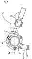
- the Fig. 1 shows a schematic plan view of an apparatus for granulating emerging from nozzles in a nozzle plate thermoplastic material according to a preferred embodiment of the invention.
- Fig. 1 the housing 6 of the device, through which a cooling medium flows, is shown, wherein an inlet 7 for the cooling medium and an outlet 8 for the cooling medium and the granules therein are provided on the housing 6.
- the inlet 7 is arranged according to the invention in the lower half of the housing 6, preferably for example in a position between four and five o'clock.
- the inlet 7 has an inlet opening 7a in the housing and a to the housing 6 hinactedd arranged inlet channel 7b, wherein the inlet channel 7b in the i Fig. 1 shown preferred embodiment is arranged rectilinear and tangential to the housing 6 hinactedd.
- the outlet 8 is further arranged in the upper half of the housing 6, preferably in a position between ten and two o'clock.
- the outlet 8 according to the invention has an outlet opening 8a in the housing 6 and an outlet channel 8b arranged tangentially away from the housing 6, the outlet channel 8b being rectilinear over a length of at least twice the largest inner diameter of the cross section of the housing 6.
- the length of the rectilinear course of the outlet channel 8b is also at least ten times the local diameter of the outlet channel 8b at the corresponding location of the outlet channel 8b.
- the length may be due to the clarity of the Fig. 1 There are not fully reproduced there and extends accordingly further on in the Fig. 1 shown length out.
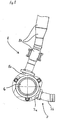
- the Fig. 2 shows a schematic plan view of a device for granulating according to another preferred embodiment of the invention.
- illustrated embodiment of the invention differs from the in Fig. 1 illustrated embodiment of the invention only in that in Fig. 2 the outlet channel 8b is not completely rectilinear, but runs essentially in a straight line. In this case, the outlet channel 8b according to the illustration of Fig.
- the outlet channel 8b there also has, over the length of its essentially rectilinear course, a change in cross section, namely a widening of the cross section, wherein over the length of the change in cross section the opening angle of the outlet channel 8b there according to the representation of FIG Fig. 2 is about 10 degrees, based on the local center axis of the outlet channel 8b.
- the Fig. 3 shows in a schematic sectional view of a device according to a preferred embodiment of the invention, taken along the section AA in Fig. 1 ,
- the apparatus according to the invention for granulating melt material emerging from nozzles 1 in a perforated plate 2 can be seen.
- the melt for example of the thermoplastic material
- the perforated plate 2 is a knife assembly with at least one knife 3, driven by a motor (not shown), opposite.
- the knife assembly is shown in dashed lines.
- At least one blade 3 passes over the nozzles 1 in the perforated plate 2 and separates granules from the emerging melt material during the production process.
- the device comprises the housing 6, which adjoins the perforated plate 2, at least surrounds the at least one knife 3 of the knife assembly and flows through the cooling medium, wherein on the housing 6 of the invention the inlet 7 for the cooling medium and the outlet 8 according to the invention for the cooling medium and the granules therein is provided.
- the inlet 7 is arranged only in the lower half of the housing 6 with an inlet opening 7a in the housing 6, wherein the inlet on the housing seen in the longitudinal direction of the housing 6 in a rear portion of the housing 6 in a perforated plate 2 remote area is arranged.
- the outlet 8 is arranged in the upper half of the housing 6 and has an outlet opening 8a in the housing 6 and an outlet channel 8b arranged tangentially away from the housing 6, the outlet channel 8b being at least twice the largest inside diameter of the cross section of the body Housing 6 is rectilinear or substantially rectilinear, which is in Fig. 3 only indicated, since the length of the outlet channel 8b in the figure is not fully representable.
- the outlet 8 is in accordance with the in Fig. 3 shown embodiment of the invention on the housing 6 in a viewed in the longitudinal direction of the housing 6 front portion of the housing 6 in the region of movement of the at least one blade 3 in the perforated plate 2 is arranged.
- an efficient granulation can be achieved in a structurally simple manner with simultaneous reliable and rapid transport of the granules in the cooling medium, in particular a reliable bonding of the granules in the cooling medium can be avoided.
Landscapes
- Engineering & Computer Science (AREA)
- Mechanical Engineering (AREA)
- Processing And Handling Of Plastics And Other Materials For Molding In General (AREA)
- Glanulating (AREA)
Claims (7)
- Dispositif de granulation de matière fondue extrudée à partir de buses (1) dans une plaque perforée (2), ladite plaque perforée (2) étant placée face à un ensemble de lames comprenant au moins une lame (3) actionné par un moteur de sorte que la ou les lames (3) balaie les buses (1) dans la plaque perforée (2) et sépare ce faisant des granulats du matériau en fusion extrudé, le dispositif présentant un boîtier (6) accolé à la plaque perforée (2) qui entoure au moins la ou les lames (3) de l'ensemble de lames et qui est parcouru par un fluide de refroidissement et ledit boîtier (6) étant doté d'une admission (7) pour le fluide de refroidissement et d'une évacuation (8) pour le fluide de refroidissement et les granulats qui s'y trouvent,
et
l'admission (7) étant uniquement disposée dans la moitié inférieure du boîtier (6) et présentant un orifice d'admission (7a) dans le boîtier (6), ainsi qu'un conduit d'admission (7b) conduisant au boîtier (6), tandis que l'évacuation (8) est disposée dans la moitié supérieure du boîtier (6) et présente un orifice d'évacuation (8a) dans le boîtier (6) et un conduit d'évacuation (8b), ledit conduit d'évacuation (8b) étant rectiligne ou sensiblement rectiligne sur une longueur égale à au moins le double du plus grand diamètre intérieur de la section du boîtier (6)
caractérisé en ce que
le conduit d'évacuation (8b) s'éloigne tangentiellement du boîtier (6) et ledit orifice d'admission (7a) étant disposé dans une partie arrière du boîtier (6) vu dans le sens longitudinal, éloignée de la plaque perforée (2), tandis que ledit orifice d'évacuation (8a) est disposé dans une partie avant du boîtier (6) vu dans le sens longitudinal, dans la zone de balayage de la ou des lames (3) à proximité de la plaque perforée (2). - Dispositif conforme à la revendication 1 caractérisé par la disposition tangentielle par rapport au boîtier (6) du conduit d'admission (7b) y conduisant.
- Dispositif conforme à l'une des revendications 1 à 2, caractérisé par la disposition du même côté du boîtier (6) vu en coupe de l'admission (7) et de l'évacuation (8).
- Dispositif conforme à l'une des revendications 1 à 3, caractérisé par une courbure du conduit d'évacuation (8b) au niveau de sa partie rectiligne ou sensiblement rectiligne dont l'angle de courbure est inférieur à 30 °, de préférence inférieur à 15 °, mesuré entre l'axe central du début de la partie rectiligne ou sensiblement rectiligne du conduit d'évacuation (8b) et l'axe central de la fin de la partie rectiligne ou sensiblement rectiligne du conduit d'évacuation (8b).
- Dispositif conforme à l'une des revendications 1 à 4, caractérisé par la section constante du conduit d'évacuation (8b) sur la longueur de sa partie rectiligne ou sensiblement rectiligne.
- Dispositif conforme à l'une des revendications 1 à 4, caractérisé par une ou plusieurs modifications de section du conduit d'évacuation (8b) sur la longueur de sa partie rectiligne ou sensiblement rectiligne, les élargissements ou rétrécissements de la section présentant chacun un angle d'ouverture inférieur à 15 ° par rapport à l'axe central du conduit d'évacuation (8b) à cet endroit.
- Dispositif conforme à l'une des revendications 1 à 6, caractérisé en ce que la longueur de la partie rectiligne ou sensiblement rectiligne du conduit d'évacuation (8b) est égale à au moins dix fois le diamètre local du conduit d'évacuation (8b).
Applications Claiming Priority (2)
| Application Number | Priority Date | Filing Date | Title |
|---|---|---|---|
| DE202009015876U DE202009015876U1 (de) | 2009-11-20 | 2009-11-20 | Vorrichtung zum Granulieren |
| PCT/EP2010/007017 WO2011060938A1 (fr) | 2009-11-20 | 2010-11-18 | Dispositif de granulation |
Publications (2)
| Publication Number | Publication Date |
|---|---|
| EP2501531A1 EP2501531A1 (fr) | 2012-09-26 |
| EP2501531B1 true EP2501531B1 (fr) | 2019-10-30 |
Family
ID=41795637
Family Applications (1)
| Application Number | Title | Priority Date | Filing Date |
|---|---|---|---|
| EP10781620.9A Active EP2501531B1 (fr) | 2009-11-20 | 2010-11-18 | Appareil pour granuler |
Country Status (7)
| Country | Link |
|---|---|
| US (1) | US20120231102A1 (fr) |
| EP (1) | EP2501531B1 (fr) |
| JP (1) | JP5948247B2 (fr) |
| CN (1) | CN102470555B (fr) |
| DE (1) | DE202009015876U1 (fr) |
| TW (1) | TWI537116B (fr) |
| WO (1) | WO2011060938A1 (fr) |
Families Citing this family (2)
| Publication number | Priority date | Publication date | Assignee | Title |
|---|---|---|---|---|
| CN102615735B (zh) * | 2012-03-24 | 2014-05-28 | 佛山欣涛新材料科技有限公司 | 一种热熔胶粒生产流水线 |
| CN104209058A (zh) * | 2013-05-30 | 2014-12-17 | 杜广安 | 木屑颗粒成型机 |
Family Cites Families (23)
| Publication number | Priority date | Publication date | Assignee | Title |
|---|---|---|---|---|
| NL298480A (fr) * | 1962-09-27 | |||
| DE1454888B2 (de) * | 1964-03-24 | 1971-09-30 | Werner & Pfleiderer, 7000 Stuttgart | Vorrichtung zum granulieren von thermoplastischen kunst stoffen |
| US3892834A (en) * | 1974-01-09 | 1975-07-01 | Phillips Petroleum Co | Surface active agent to reduce agglomeration in dry die-face pelletizing |
| GB1514160A (en) * | 1975-07-07 | 1978-06-14 | Farrel Bridge Ltd | Extrusion pelletising machines |
| DD132475B1 (de) * | 1977-06-22 | 1980-01-30 | Hans Jarausch | Vorrichtung zum granulieren von thermoplastischen kunststoffen |
| EP0305862A1 (fr) * | 1987-09-04 | 1989-03-08 | General Electric Company | Procédé en une étape pour la production de perles expansibles en mousse |
| JPH06182760A (ja) * | 1992-12-15 | 1994-07-05 | Japan Steel Works Ltd:The | ミニペレット造粒方法及び装置 |
| US5624688A (en) * | 1995-10-12 | 1997-04-29 | Gala Industries, Inc. | Self-aligning cutter hub |
| US5629028A (en) * | 1995-11-07 | 1997-05-13 | The Conair Group, Inc. | Underwater pelletizer having sealed heat transfer tubes embedded in extrusion die |
| US6551087B1 (en) | 1999-09-21 | 2003-04-22 | Gala Industries, Inc. | Flow guide for underwater pelletizer |
| DE10137525A1 (de) * | 2001-08-01 | 2003-02-13 | Rieter Automatik Gmbh | Vorrichtung zum Granulieren von aus Düsen austretenden thermoplastischem Kunststoff |
| DE10137524A1 (de) * | 2001-08-01 | 2003-02-13 | Rieter Automatik Gmbh | Vorrichtung zum Granulieren von aus Düsen austretenden thermoplastischem Kunststoff |
| ITMI20012706A1 (it) * | 2001-12-20 | 2003-06-20 | Enichem Spa | Procedimento per la produzione di granuli di polimeri termoplastici espandibili ed apparecchiatura adatta allo scopo |
| US6848639B2 (en) * | 2002-02-12 | 2005-02-01 | Borsig Gmbh | Low turbulent flow high speed cutter knife |
| CA2482056A1 (fr) * | 2003-10-10 | 2005-04-10 | Eastman Chemical Company | Cristallisation thermique d'un polyester fondu dans un fluide |
| TWI440658B (zh) * | 2005-08-31 | 2014-06-11 | Gala Inc | 用於水中粒化具減低含水量的聚合體生物材料複合物之方法及裝置 |
| JP4592572B2 (ja) * | 2005-11-25 | 2010-12-01 | 株式会社神戸製鋼所 | 水中カット造粒装置 |
| CH711770B1 (de) * | 2006-03-13 | 2017-05-15 | Uhde Inventa-Fischer Ag | Verfahren zur Herstellung eines nicht klebenden Granulats aus einem Polyestermaterial und zur Weiterverarbeitung eines so hergestellten Granulats. |
| CN102617999B (zh) * | 2007-03-29 | 2014-06-25 | 积水化成品工业株式会社 | 模内发泡成形用聚乳酸系树脂发泡颗粒及其制造方法以及聚乳酸系树脂发泡成形体的制造方法 |
| US8969435B2 (en) * | 2007-08-28 | 2015-03-03 | Gala Industries, Inc. | Method and apparatus for enhanced minimal shear molding utilizing extrusional, pelletization, and melt rheological control of pellets and micropellets and molded objects made therefrom |
| US20090110833A1 (en) * | 2007-10-31 | 2009-04-30 | Gala Industries, Inc. | Method for abrasion-resistant non-stick surface treatments for pelletization and drying process equipment components |
| US8080196B2 (en) * | 2008-02-12 | 2011-12-20 | Gala Industries, Inc. | Method and apparatus to achieve crystallization of polymers utilizing multiple processing systems |
| DE102009006123B4 (de) * | 2009-01-26 | 2019-01-10 | Maag Automatik Gmbh | Verfahren und Vorrichtung zum Granulieren von thermoplastischem Kunststoffmaterial |
-
2009
- 2009-11-20 DE DE202009015876U patent/DE202009015876U1/de not_active Expired - Lifetime
-
2010
- 2010-11-17 TW TW099139460A patent/TWI537116B/zh active
- 2010-11-18 WO PCT/EP2010/007017 patent/WO2011060938A1/fr not_active Ceased
- 2010-11-18 CN CN201080026441.9A patent/CN102470555B/zh active Active
- 2010-11-18 EP EP10781620.9A patent/EP2501531B1/fr active Active
- 2010-11-18 JP JP2012539229A patent/JP5948247B2/ja active Active
-
2012
- 2012-05-18 US US13/475,791 patent/US20120231102A1/en not_active Abandoned
Non-Patent Citations (1)
| Title |
|---|
| None * |
Also Published As
| Publication number | Publication date |
|---|---|
| DE202009015876U1 (de) | 2010-03-04 |
| JP2013511400A (ja) | 2013-04-04 |
| TW201127589A (en) | 2011-08-16 |
| JP5948247B2 (ja) | 2016-07-06 |
| TWI537116B (zh) | 2016-06-11 |
| CN102470555B (zh) | 2016-06-08 |
| CN102470555A (zh) | 2012-05-23 |
| US20120231102A1 (en) | 2012-09-13 |
| EP2501531A1 (fr) | 2012-09-26 |
| WO2011060938A1 (fr) | 2011-05-26 |
Similar Documents
| Publication | Publication Date | Title |
|---|---|---|
| EP1970180B1 (fr) | Valve de démarrage pour granulateur | |
| EP0701505B1 (fr) | Dispositif pour le degazage d'une matiere synthetique thermoplastique | |
| EP2576180B1 (fr) | Dispositif de filtration pour matériau visqueux | |
| DE10017408A1 (de) | Behandlungs-Tunelleinrichtung, insbesondere Kühltunell | |
| DE102013020316A1 (de) | Verfahren zur Herstellung von Granulatkörnern aus einem Schmelzematerial | |
| EP2501531B1 (fr) | Appareil pour granuler | |
| EP2892704B1 (fr) | Buse à canal chaud d'injection de matiere thermoplastique dans un moule | |
| EP3953126B1 (fr) | Agencement destiné à la granulation d'un matériau extrudé | |
| EP3645149B1 (fr) | Distributeur de fluide | |
| EP1288600B1 (fr) | Dispositif de séchage d'un matériau en vrac en contre-courant avec un fluide gazeux | |
| DE10138333C2 (de) | Vorrichtung zum Auspressen fließfähiger Substanzen | |
| EP3459701B1 (fr) | Dispositif de coupe pour découper des matières pâteuses | |
| DD132475B1 (de) | Vorrichtung zum granulieren von thermoplastischen kunststoffen | |
| EP3393751B1 (fr) | Extrudeuse avec un déflecteur à guider le flux aux sections respective de la plaque du filtre | |
| EP2861396A1 (fr) | Plaque à buses pour un dispositif de granulation et dispositif de granulation comprenant une plaque à buses | |
| AT510262B1 (de) | Vorrichtung zum granulieren von kunststoff | |
| DE102009032993A1 (de) | Vorrichtung und Verfahren zum Granulieren von Kunststoffmaterial | |
| DE102010052153A1 (de) | Vorrichtung zum Verhindern des unkontrollierten Austritts von Schmelze aus einer Düsenplatte | |
| EP3953128A1 (fr) | Dispositif de refroidissement de matériaux particulaires | |
| DE19834302A1 (de) | Filtereinrichtung für Strangpressen und Spritzgießmaschinen | |
| EP4617027A1 (fr) | Hotte de granulation et dispositif de granulation | |
| DE19735571C2 (de) | Spinneinrichtung zum Ausspinnen von Filamenten aus synthetischen Polymeren | |
| EP3199314B1 (fr) | Dispositif de production de tiges, et dispositif de granulation associé | |
| AT523143B1 (de) | Anordnung zum Granulieren von extrudiertem Material | |
| EP3287254B1 (fr) | Structure de mélangeur pour un outil pour film et outil pour film |
Legal Events
| Date | Code | Title | Description |
|---|---|---|---|
| PUAI | Public reference made under article 153(3) epc to a published international application that has entered the european phase |
Free format text: ORIGINAL CODE: 0009012 |
|
| 17P | Request for examination filed |
Effective date: 20120616 |
|
| AK | Designated contracting states |
Kind code of ref document: A1 Designated state(s): AL AT BE BG CH CY CZ DE DK EE ES FI FR GB GR HR HU IE IS IT LI LT LU LV MC MK MT NL NO PL PT RO RS SE SI SK SM TR |
|
| DAX | Request for extension of the european patent (deleted) | ||
| STAA | Information on the status of an ep patent application or granted ep patent |
Free format text: STATUS: EXAMINATION IS IN PROGRESS |
|
| 17Q | First examination report despatched |
Effective date: 20170220 |
|
| RAP1 | Party data changed (applicant data changed or rights of an application transferred) |
Owner name: MAAG AUTOMATIK GMBH |
|
| GRAP | Despatch of communication of intention to grant a patent |
Free format text: ORIGINAL CODE: EPIDOSNIGR1 |
|
| STAA | Information on the status of an ep patent application or granted ep patent |
Free format text: STATUS: GRANT OF PATENT IS INTENDED |
|
| INTG | Intention to grant announced |
Effective date: 20190108 |
|
| GRAJ | Information related to disapproval of communication of intention to grant by the applicant or resumption of examination proceedings by the epo deleted |
Free format text: ORIGINAL CODE: EPIDOSDIGR1 |
|
| STAA | Information on the status of an ep patent application or granted ep patent |
Free format text: STATUS: EXAMINATION IS IN PROGRESS |
|
| GRAS | Grant fee paid |
Free format text: ORIGINAL CODE: EPIDOSNIGR3 |
|
| STAA | Information on the status of an ep patent application or granted ep patent |
Free format text: STATUS: GRANT OF PATENT IS INTENDED |
|
| GRAP | Despatch of communication of intention to grant a patent |
Free format text: ORIGINAL CODE: EPIDOSNIGR1 |
|
| INTG | Intention to grant announced |
Effective date: 20190529 |
|
| GRAJ | Information related to disapproval of communication of intention to grant by the applicant or resumption of examination proceedings by the epo deleted |
Free format text: ORIGINAL CODE: EPIDOSDIGR1 |
|
| GRAL | Information related to payment of fee for publishing/printing deleted |
Free format text: ORIGINAL CODE: EPIDOSDIGR3 |
|
| STAA | Information on the status of an ep patent application or granted ep patent |
Free format text: STATUS: EXAMINATION IS IN PROGRESS |
|
| STAA | Information on the status of an ep patent application or granted ep patent |
Free format text: STATUS: GRANT OF PATENT IS INTENDED |
|
| GRAA | (expected) grant |
Free format text: ORIGINAL CODE: 0009210 |
|
| STAA | Information on the status of an ep patent application or granted ep patent |
Free format text: STATUS: THE PATENT HAS BEEN GRANTED |
|
| INTC | Intention to grant announced (deleted) | ||
| AK | Designated contracting states |
Kind code of ref document: B1 Designated state(s): AL AT BE BG CH CY CZ DE DK EE ES FI FR GB GR HR HU IE IS IT LI LT LU LV MC MK MT NL NO PL PT RO RS SE SI SK SM TR |
|
| REG | Reference to a national code |
Ref country code: GB Ref legal event code: FG4D Free format text: NOT ENGLISH |
|
| REG | Reference to a national code |
Ref country code: CH Ref legal event code: EP |
|
| REG | Reference to a national code |
Ref country code: AT Ref legal event code: REF Ref document number: 1195650 Country of ref document: AT Kind code of ref document: T Effective date: 20191115 |
|
| REG | Reference to a national code |
Ref country code: DE Ref legal event code: R096 Ref document number: 502010016343 Country of ref document: DE |
|
| REG | Reference to a national code |
Ref country code: IE Ref legal event code: FG4D Free format text: LANGUAGE OF EP DOCUMENT: GERMAN |
|
| REG | Reference to a national code |
Ref country code: DE Ref legal event code: R082 Ref document number: 502010016343 Country of ref document: DE Representative=s name: KUHNEN & WACKER PATENT- UND RECHTSANWALTSBUERO, DE Ref country code: DE Ref legal event code: R082 Ref document number: 502010016343 Country of ref document: DE Representative=s name: LORENZ SEIDLER GOSSEL RECHTSANWAELTE PATENTANW, DE |
|
| REG | Reference to a national code |
Ref country code: LT Ref legal event code: MG4D |
|
| REG | Reference to a national code |
Ref country code: DE Ref legal event code: R082 Ref document number: 502010016343 Country of ref document: DE Representative=s name: LORENZ SEIDLER GOSSEL RECHTSANWAELTE PATENTANW, DE |
|
| REG | Reference to a national code |
Ref country code: DE Ref legal event code: R082 Ref document number: 502010016343 Country of ref document: DE Representative=s name: LORENZ SEIDLER GOSSEL RECHTSANWAELTE PATENTANW, DE |
|
| PG25 | Lapsed in a contracting state [announced via postgrant information from national office to epo] |
Ref country code: PT Free format text: LAPSE BECAUSE OF FAILURE TO SUBMIT A TRANSLATION OF THE DESCRIPTION OR TO PAY THE FEE WITHIN THE PRESCRIBED TIME-LIMIT Effective date: 20200302 Ref country code: LV Free format text: LAPSE BECAUSE OF FAILURE TO SUBMIT A TRANSLATION OF THE DESCRIPTION OR TO PAY THE FEE WITHIN THE PRESCRIBED TIME-LIMIT Effective date: 20191030 Ref country code: SE Free format text: LAPSE BECAUSE OF FAILURE TO SUBMIT A TRANSLATION OF THE DESCRIPTION OR TO PAY THE FEE WITHIN THE PRESCRIBED TIME-LIMIT Effective date: 20191030 Ref country code: FI Free format text: LAPSE BECAUSE OF FAILURE TO SUBMIT A TRANSLATION OF THE DESCRIPTION OR TO PAY THE FEE WITHIN THE PRESCRIBED TIME-LIMIT Effective date: 20191030 Ref country code: BG Free format text: LAPSE BECAUSE OF FAILURE TO SUBMIT A TRANSLATION OF THE DESCRIPTION OR TO PAY THE FEE WITHIN THE PRESCRIBED TIME-LIMIT Effective date: 20200130 Ref country code: GR Free format text: LAPSE BECAUSE OF FAILURE TO SUBMIT A TRANSLATION OF THE DESCRIPTION OR TO PAY THE FEE WITHIN THE PRESCRIBED TIME-LIMIT Effective date: 20200131 Ref country code: NO Free format text: LAPSE BECAUSE OF FAILURE TO SUBMIT A TRANSLATION OF THE DESCRIPTION OR TO PAY THE FEE WITHIN THE PRESCRIBED TIME-LIMIT Effective date: 20200130 Ref country code: PL Free format text: LAPSE BECAUSE OF FAILURE TO SUBMIT A TRANSLATION OF THE DESCRIPTION OR TO PAY THE FEE WITHIN THE PRESCRIBED TIME-LIMIT Effective date: 20191030 Ref country code: NL Free format text: LAPSE BECAUSE OF FAILURE TO SUBMIT A TRANSLATION OF THE DESCRIPTION OR TO PAY THE FEE WITHIN THE PRESCRIBED TIME-LIMIT Effective date: 20191030 Ref country code: ES Free format text: LAPSE BECAUSE OF FAILURE TO SUBMIT A TRANSLATION OF THE DESCRIPTION OR TO PAY THE FEE WITHIN THE PRESCRIBED TIME-LIMIT Effective date: 20191030 Ref country code: LT Free format text: LAPSE BECAUSE OF FAILURE TO SUBMIT A TRANSLATION OF THE DESCRIPTION OR TO PAY THE FEE WITHIN THE PRESCRIBED TIME-LIMIT Effective date: 20191030 |
|
| REG | Reference to a national code |
Ref country code: NL Ref legal event code: MP Effective date: 20191030 |
|
| PG25 | Lapsed in a contracting state [announced via postgrant information from national office to epo] |
Ref country code: HR Free format text: LAPSE BECAUSE OF FAILURE TO SUBMIT A TRANSLATION OF THE DESCRIPTION OR TO PAY THE FEE WITHIN THE PRESCRIBED TIME-LIMIT Effective date: 20191030 Ref country code: IS Free format text: LAPSE BECAUSE OF FAILURE TO SUBMIT A TRANSLATION OF THE DESCRIPTION OR TO PAY THE FEE WITHIN THE PRESCRIBED TIME-LIMIT Effective date: 20200229 Ref country code: RS Free format text: LAPSE BECAUSE OF FAILURE TO SUBMIT A TRANSLATION OF THE DESCRIPTION OR TO PAY THE FEE WITHIN THE PRESCRIBED TIME-LIMIT Effective date: 20191030 |
|
| PG25 | Lapsed in a contracting state [announced via postgrant information from national office to epo] |
Ref country code: AL Free format text: LAPSE BECAUSE OF FAILURE TO SUBMIT A TRANSLATION OF THE DESCRIPTION OR TO PAY THE FEE WITHIN THE PRESCRIBED TIME-LIMIT Effective date: 20191030 |
|
| REG | Reference to a national code |
Ref country code: CH Ref legal event code: PL |
|
| PG25 | Lapsed in a contracting state [announced via postgrant information from national office to epo] |
Ref country code: EE Free format text: LAPSE BECAUSE OF FAILURE TO SUBMIT A TRANSLATION OF THE DESCRIPTION OR TO PAY THE FEE WITHIN THE PRESCRIBED TIME-LIMIT Effective date: 20191030 Ref country code: RO Free format text: LAPSE BECAUSE OF FAILURE TO SUBMIT A TRANSLATION OF THE DESCRIPTION OR TO PAY THE FEE WITHIN THE PRESCRIBED TIME-LIMIT Effective date: 20191030 Ref country code: CZ Free format text: LAPSE BECAUSE OF FAILURE TO SUBMIT A TRANSLATION OF THE DESCRIPTION OR TO PAY THE FEE WITHIN THE PRESCRIBED TIME-LIMIT Effective date: 20191030 Ref country code: MC Free format text: LAPSE BECAUSE OF FAILURE TO SUBMIT A TRANSLATION OF THE DESCRIPTION OR TO PAY THE FEE WITHIN THE PRESCRIBED TIME-LIMIT Effective date: 20191030 Ref country code: LI Free format text: LAPSE BECAUSE OF NON-PAYMENT OF DUE FEES Effective date: 20191130 Ref country code: CH Free format text: LAPSE BECAUSE OF NON-PAYMENT OF DUE FEES Effective date: 20191130 Ref country code: DK Free format text: LAPSE BECAUSE OF FAILURE TO SUBMIT A TRANSLATION OF THE DESCRIPTION OR TO PAY THE FEE WITHIN THE PRESCRIBED TIME-LIMIT Effective date: 20191030 Ref country code: LU Free format text: LAPSE BECAUSE OF NON-PAYMENT OF DUE FEES Effective date: 20191118 |
|
| REG | Reference to a national code |
Ref country code: DE Ref legal event code: R097 Ref document number: 502010016343 Country of ref document: DE |
|
| REG | Reference to a national code |
Ref country code: BE Ref legal event code: MM Effective date: 20191130 |
|
| PG25 | Lapsed in a contracting state [announced via postgrant information from national office to epo] |
Ref country code: SM Free format text: LAPSE BECAUSE OF FAILURE TO SUBMIT A TRANSLATION OF THE DESCRIPTION OR TO PAY THE FEE WITHIN THE PRESCRIBED TIME-LIMIT Effective date: 20191030 Ref country code: SK Free format text: LAPSE BECAUSE OF FAILURE TO SUBMIT A TRANSLATION OF THE DESCRIPTION OR TO PAY THE FEE WITHIN THE PRESCRIBED TIME-LIMIT Effective date: 20191030 |
|
| PLBE | No opposition filed within time limit |
Free format text: ORIGINAL CODE: 0009261 |
|
| STAA | Information on the status of an ep patent application or granted ep patent |
Free format text: STATUS: NO OPPOSITION FILED WITHIN TIME LIMIT |
|
| GBPC | Gb: european patent ceased through non-payment of renewal fee |
Effective date: 20200130 |
|
| 26N | No opposition filed |
Effective date: 20200731 |
|
| PG25 | Lapsed in a contracting state [announced via postgrant information from national office to epo] |
Ref country code: FR Free format text: LAPSE BECAUSE OF NON-PAYMENT OF DUE FEES Effective date: 20191230 Ref country code: IE Free format text: LAPSE BECAUSE OF NON-PAYMENT OF DUE FEES Effective date: 20191118 Ref country code: GB Free format text: LAPSE BECAUSE OF NON-PAYMENT OF DUE FEES Effective date: 20200130 |
|
| PG25 | Lapsed in a contracting state [announced via postgrant information from national office to epo] |
Ref country code: SI Free format text: LAPSE BECAUSE OF FAILURE TO SUBMIT A TRANSLATION OF THE DESCRIPTION OR TO PAY THE FEE WITHIN THE PRESCRIBED TIME-LIMIT Effective date: 20191030 Ref country code: BE Free format text: LAPSE BECAUSE OF NON-PAYMENT OF DUE FEES Effective date: 20191130 |
|
| PG25 | Lapsed in a contracting state [announced via postgrant information from national office to epo] |
Ref country code: CY Free format text: LAPSE BECAUSE OF FAILURE TO SUBMIT A TRANSLATION OF THE DESCRIPTION OR TO PAY THE FEE WITHIN THE PRESCRIBED TIME-LIMIT Effective date: 20191030 |
|
| PG25 | Lapsed in a contracting state [announced via postgrant information from national office to epo] |
Ref country code: HU Free format text: LAPSE BECAUSE OF FAILURE TO SUBMIT A TRANSLATION OF THE DESCRIPTION OR TO PAY THE FEE WITHIN THE PRESCRIBED TIME-LIMIT; INVALID AB INITIO Effective date: 20101118 Ref country code: MT Free format text: LAPSE BECAUSE OF FAILURE TO SUBMIT A TRANSLATION OF THE DESCRIPTION OR TO PAY THE FEE WITHIN THE PRESCRIBED TIME-LIMIT Effective date: 20191030 |
|
| PG25 | Lapsed in a contracting state [announced via postgrant information from national office to epo] |
Ref country code: TR Free format text: LAPSE BECAUSE OF FAILURE TO SUBMIT A TRANSLATION OF THE DESCRIPTION OR TO PAY THE FEE WITHIN THE PRESCRIBED TIME-LIMIT Effective date: 20191030 |
|
| PG25 | Lapsed in a contracting state [announced via postgrant information from national office to epo] |
Ref country code: MK Free format text: LAPSE BECAUSE OF FAILURE TO SUBMIT A TRANSLATION OF THE DESCRIPTION OR TO PAY THE FEE WITHIN THE PRESCRIBED TIME-LIMIT Effective date: 20191030 |
|
| PGFP | Annual fee paid to national office [announced via postgrant information from national office to epo] |
Ref country code: DE Payment date: 20251119 Year of fee payment: 16 |
|
| PGFP | Annual fee paid to national office [announced via postgrant information from national office to epo] |
Ref country code: AT Payment date: 20251120 Year of fee payment: 16 |
|
| PGFP | Annual fee paid to national office [announced via postgrant information from national office to epo] |
Ref country code: IT Payment date: 20251125 Year of fee payment: 16 |