EP2502296B1 - Agencement pour une cellula à combustible ainsi que son procédé de fabrication - Google Patents
Agencement pour une cellula à combustible ainsi que son procédé de fabrication Download PDFInfo
- Publication number
- EP2502296B1 EP2502296B1 EP10784263.5A EP10784263A EP2502296B1 EP 2502296 B1 EP2502296 B1 EP 2502296B1 EP 10784263 A EP10784263 A EP 10784263A EP 2502296 B1 EP2502296 B1 EP 2502296B1
- Authority
- EP
- European Patent Office
- Prior art keywords
- electrolyte
- electrode
- layer
- adaptation layer
- arrangement according
- Prior art date
- Legal status (The legal status is an assumption and is not a legal conclusion. Google has not performed a legal analysis and makes no representation as to the accuracy of the status listed.)
- Active
Links
Images


Classifications
-
- H—ELECTRICITY
- H01—ELECTRIC ELEMENTS
- H01M—PROCESSES OR MEANS, e.g. BATTERIES, FOR THE DIRECT CONVERSION OF CHEMICAL ENERGY INTO ELECTRICAL ENERGY
- H01M4/00—Electrodes
- H01M4/86—Inert electrodes with catalytic activity, e.g. for fuel cells
- H01M4/8605—Porous electrodes
-
- H—ELECTRICITY
- H01—ELECTRIC ELEMENTS
- H01M—PROCESSES OR MEANS, e.g. BATTERIES, FOR THE DIRECT CONVERSION OF CHEMICAL ENERGY INTO ELECTRICAL ENERGY
- H01M8/00—Fuel cells; Manufacture thereof
- H01M8/02—Details
- H01M8/0202—Collectors; Separators, e.g. bipolar separators; Interconnectors
-
- H—ELECTRICITY
- H01—ELECTRIC ELEMENTS
- H01M—PROCESSES OR MEANS, e.g. BATTERIES, FOR THE DIRECT CONVERSION OF CHEMICAL ENERGY INTO ELECTRICAL ENERGY
- H01M4/00—Electrodes
- H01M4/86—Inert electrodes with catalytic activity, e.g. for fuel cells
- H01M4/8647—Inert electrodes with catalytic activity, e.g. for fuel cells consisting of more than one material, e.g. consisting of composites
- H01M4/8657—Inert electrodes with catalytic activity, e.g. for fuel cells consisting of more than one material, e.g. consisting of composites layered
-
- H—ELECTRICITY
- H01—ELECTRIC ELEMENTS
- H01M—PROCESSES OR MEANS, e.g. BATTERIES, FOR THE DIRECT CONVERSION OF CHEMICAL ENERGY INTO ELECTRICAL ENERGY
- H01M4/00—Electrodes
- H01M4/86—Inert electrodes with catalytic activity, e.g. for fuel cells
- H01M4/88—Processes of manufacture
- H01M4/8878—Treatment steps after deposition of the catalytic active composition or after shaping of the electrode being free-standing body
- H01M4/8892—Impregnation or coating of the catalyst layer, e.g. by an ionomer
-
- H—ELECTRICITY
- H01—ELECTRIC ELEMENTS
- H01M—PROCESSES OR MEANS, e.g. BATTERIES, FOR THE DIRECT CONVERSION OF CHEMICAL ENERGY INTO ELECTRICAL ENERGY
- H01M4/00—Electrodes
- H01M4/86—Inert electrodes with catalytic activity, e.g. for fuel cells
- H01M4/90—Selection of catalytic material
- H01M4/9016—Oxides, hydroxides or oxygenated metallic salts
- H01M4/9025—Oxides specially used in fuel cell operating at high temperature, e.g. SOFC
- H01M4/9033—Complex oxides, optionally doped, of the type M1MeO3, M1 being an alkaline earth metal or a rare earth, Me being a metal, e.g. perovskites
-
- H—ELECTRICITY
- H01—ELECTRIC ELEMENTS
- H01M—PROCESSES OR MEANS, e.g. BATTERIES, FOR THE DIRECT CONVERSION OF CHEMICAL ENERGY INTO ELECTRICAL ENERGY
- H01M8/00—Fuel cells; Manufacture thereof
- H01M8/10—Fuel cells with solid electrolytes
- H01M8/12—Fuel cells with solid electrolytes operating at high temperature, e.g. with stabilised ZrO2 electrolyte
- H01M8/1213—Fuel cells with solid electrolytes operating at high temperature, e.g. with stabilised ZrO2 electrolyte characterised by the electrode/electrolyte combination or the supporting material
-
- H—ELECTRICITY
- H01—ELECTRIC ELEMENTS
- H01M—PROCESSES OR MEANS, e.g. BATTERIES, FOR THE DIRECT CONVERSION OF CHEMICAL ENERGY INTO ELECTRICAL ENERGY
- H01M8/00—Fuel cells; Manufacture thereof
- H01M8/10—Fuel cells with solid electrolytes
- H01M8/12—Fuel cells with solid electrolytes operating at high temperature, e.g. with stabilised ZrO2 electrolyte
- H01M8/124—Fuel cells with solid electrolytes operating at high temperature, e.g. with stabilised ZrO2 electrolyte characterised by the process of manufacturing or by the material of the electrolyte
- H01M8/1246—Fuel cells with solid electrolytes operating at high temperature, e.g. with stabilised ZrO2 electrolyte characterised by the process of manufacturing or by the material of the electrolyte the electrolyte consisting of oxides
- H01M8/1253—Fuel cells with solid electrolytes operating at high temperature, e.g. with stabilised ZrO2 electrolyte characterised by the process of manufacturing or by the material of the electrolyte the electrolyte consisting of oxides the electrolyte containing zirconium oxide
-
- H—ELECTRICITY
- H01—ELECTRIC ELEMENTS
- H01M—PROCESSES OR MEANS, e.g. BATTERIES, FOR THE DIRECT CONVERSION OF CHEMICAL ENERGY INTO ELECTRICAL ENERGY
- H01M8/00—Fuel cells; Manufacture thereof
- H01M8/10—Fuel cells with solid electrolytes
- H01M8/12—Fuel cells with solid electrolytes operating at high temperature, e.g. with stabilised ZrO2 electrolyte
- H01M8/124—Fuel cells with solid electrolytes operating at high temperature, e.g. with stabilised ZrO2 electrolyte characterised by the process of manufacturing or by the material of the electrolyte
- H01M8/1246—Fuel cells with solid electrolytes operating at high temperature, e.g. with stabilised ZrO2 electrolyte characterised by the process of manufacturing or by the material of the electrolyte the electrolyte consisting of oxides
- H01M8/126—Fuel cells with solid electrolytes operating at high temperature, e.g. with stabilised ZrO2 electrolyte characterised by the process of manufacturing or by the material of the electrolyte the electrolyte consisting of oxides the electrolyte containing cerium oxide
-
- Y—GENERAL TAGGING OF NEW TECHNOLOGICAL DEVELOPMENTS; GENERAL TAGGING OF CROSS-SECTIONAL TECHNOLOGIES SPANNING OVER SEVERAL SECTIONS OF THE IPC; TECHNICAL SUBJECTS COVERED BY FORMER USPC CROSS-REFERENCE ART COLLECTIONS [XRACs] AND DIGESTS
- Y02—TECHNOLOGIES OR APPLICATIONS FOR MITIGATION OR ADAPTATION AGAINST CLIMATE CHANGE
- Y02E—REDUCTION OF GREENHOUSE GAS [GHG] EMISSIONS, RELATED TO ENERGY GENERATION, TRANSMISSION OR DISTRIBUTION
- Y02E60/00—Enabling technologies; Technologies with a potential or indirect contribution to GHG emissions mitigation
- Y02E60/30—Hydrogen technology
- Y02E60/50—Fuel cells
-
- Y—GENERAL TAGGING OF NEW TECHNOLOGICAL DEVELOPMENTS; GENERAL TAGGING OF CROSS-SECTIONAL TECHNOLOGIES SPANNING OVER SEVERAL SECTIONS OF THE IPC; TECHNICAL SUBJECTS COVERED BY FORMER USPC CROSS-REFERENCE ART COLLECTIONS [XRACs] AND DIGESTS
- Y02—TECHNOLOGIES OR APPLICATIONS FOR MITIGATION OR ADAPTATION AGAINST CLIMATE CHANGE
- Y02P—CLIMATE CHANGE MITIGATION TECHNOLOGIES IN THE PRODUCTION OR PROCESSING OF GOODS
- Y02P70/00—Climate change mitigation technologies in the production process for final industrial or consumer products
- Y02P70/50—Manufacturing or production processes characterised by the final manufactured product
Definitions
- the invention relates to an arrangement for a fuel cell, with an electrode and an electrolyte, and to a method for producing the arrangement.
- a substrate is usually used, on which an electrolyte and the two electrodes (cathode and anode) are applied. For example, first the anode, then the electrolyte and finally the cathode are applied to the substrate.
- These components of the fuel cell, which are applied in layers, are electrochemically active cell layers and are also referred to as cathode-electrolyte-anode units (KEA units), as described, for example, in DE 103 43 652 A1 is known.
- the substrate acts as a mechanical support for the KEA unit and is, for example, ceramic or metallic.
- a metallic substrate for example a porous body consisting of sintered or pressed metal particles.
- Metallic substrates have the advantage that they enable a good thermal adaptation to a so-called interconnector and a technically simple electrical contact with this interconnector.
- the interconnector - also known as a bipolar plate or current collector - is arranged between two fuel cells and connects the individual fuel cells electrically in series.
- the interconnectors also mechanically support the fuel cells and separate and guide the reaction gases on the anode and cathode sides.
- the electrolyte is arranged between the anode and the cathode.
- the electrolyte has to meet several requirements. It must conduct oxygen ions and at the same time be insulating for electrons. In addition, the electrolyte must be gas-tight. In addition, an undesirable chemical reaction between the electrolyte and an adjacent electrode must be avoided.
- DE 10 2007 015 358 A1 a multilayer structure of an electrolyte from at least three layers is provided.
- a method for producing a thin electrolyte layer on a porous electrode in which a suspension comprising electrode material is first poured onto an electrode and dried (intermediate electrode layer), the size of the solids content of this suspension being selected such that after drying, the intermediate electrode layer is one has an average pore size that is smaller than the average pore size of the electrode layer. A further suspension comprising electrolyte material is then poured onto this intermediate electrode layer and dried.
- the invention has for its object to provide an arrangement that simplifies the construction of a fuel cell.
- the invention is also based on the object of providing a method for producing such an arrangement.
- an adaptation layer is provided in the arrangement between an electrode and the electrolyte.
- This adaptation layer brings about a good connection or adaptation of the electrolyte to the electrode. Furthermore, it supports a flat structure of the arrangement or the fuel cell if a metallic porous carrier substrate is provided for the electrodes and the electrolyte.
- metallic porous carrier substrates are mechanically more stable in comparison to ceramic carrier substrates and can be provided with a particularly small substrate thickness.
- the gas-tight electrolyte should be made as thin as possible. This requires the smallest possible roughness on the electrode surface associated with the electrolyte (eg anode surface). Accordingly, the electrode material must be applied to the carrier substrate in such a way that this desired low surface roughness is achieved on the electrode. This is opposed by the relatively large surface roughness of the metallic porous carrier substrate.
- the average pore size of the adaptation layer is smaller than the average pore size of the electrode. This ratio of the average pore sizes applies at least to the near-surface layer regions of the surfaces of the electrolyte facing Electrode layer and adaptation layer. This ratio preferably applies to the entire layer thickness of the electrode and the adaptation layer.
- a surface structure is made available in the arrangement which technically simplifies the application of a gas-tight thin-layer electrolyte.
- PVD physical vapor deposition
- a single thin electrolyte layer is therefore sufficient for the proper functioning of the fuel cell, which simplifies the manufacture of the fuel cell.
- the internal cell resistance of the fuel cell is significantly reduced compared to fuel cells with plasma-sprayed electrolytes, which require a layer thickness of approx. 40 ⁇ m for sufficient gas tightness, which means that higher power yields can be achieved.
- the adaptation layer can be selected in terms of material and structure, in particular pore structure, such that an electrolyte can always be applied to an electrode (anode or cathode) with the adaptation layer interposed.
- the adaptation layer is used in the case of reduced anode layer structures on which a gas-tight electrolyte layer cannot be applied directly.
- reduced anode layer structures arise, for example, in connection with metallic substrates.
- These substrates are preferably produced by powder metallurgy and in particular are provided in the form of plates.
- a central area of this substrate is porous and serves as a mechanical support for the electrochemically active cell layers.
- These cell layers can be, for example, by wet chemical coating (such as screen printing or wet powder spraying) with subsequent sintering or by thermal spraying processes (such as plasma spraying or high-speed flame spraying) getting produced.
- Metallic carrier substrates have the advantage over ceramic carrier substrates that they are thermally more resilient and more redox-stable during operation.
- the anode structure applied to the carrier substrate is sintered in a reduced atmosphere, so that the anode structure is in a reduced, porous form.
- the nickel oxide contained in the anode structure before sintering is reduced during the sintering, which leads to a coarsening of its grain size due to the high sintering activity, and pores with relatively large diameters (for example 2 ⁇ m) are formed.
- Such a surface structure of the anode is often not suitable for applying a gas-tight thin-film electrolyte directly to the anode structure.
- the desired gas tightness of the electrolyte is not guaranteed if it is to be applied to the anode structure by means of gas phase deposition (eg PVD process). This problem is solved by means of the adaptation layer described above.
- the roughness can be used to physically characterize a surface.
- the primary profile was measured optically (confocal laser topograph) and the filtered roughness profile and the roughness values were calculated in accordance with DIN EN ISO 11562 and 4287.
- the lengths of the sensing distance ( I t ), measuring distances ( I n ) and individual measuring distances ( I r ) were selected in accordance with DIN EN ISO 4288.
- the arithmetic mean roughness value R a indicates the arithmetic mean of the amounts of all profile values of a roughness profile.
- the quadratic mean roughness value R q (also referred to as mean surface roughness R q ) is the quadratic mean value of all profile values and weights outliers more than the arithmetic mean roughness value R a .
- the average roughness depth R z is defined according to DIN EN ISO 4287 as the arithmetic mean of the individual roughness depths of all individual measuring sections.
- a Single roughness means the distance between the highest peak and the deepest groove in a single measurement section. The entire measuring section is divided into 5 consecutive segments of the same size (individual measuring sections). Since the R z value is determined by the deepest valleys and highest peaks, this is particularly dependent on the measurement method used. In contrast to the optical method used here, it must be taken into account, for example, with mechanical stylus methods that depending on the tip geometry used, not all of the pointed valleys can be captured.
- bumps of this wavelength do not yet play a decisive role in the quality and tightness of the layer, but bumps with a significantly smaller wavelength.
- micro-roughness is used in this invention, which is based on a limit wavelength of 0.15 mm for otherwise identical total measuring sections.
- These micro roughnesses were measured accordingly R a ⁇ .
- the average pore size and the sintered grain size can be used as further characteristic parameters for describing the properties of a sintered layer. Both dimensions can be determined for any structure, including open pores, using the line-cutting method on scanning electron microscope images of cross sections.
- the individual phases are first of all shown in the images via contrast differences, grain shape or element analysis (e.g. energy dispersive X-ray spectroscopy, EDX) marked accordingly, then statistically drawn straight lines and the intersections at the transitions between the different phases marked.
- the average value of all lengths of the route sections thus created, which lie in one phase reflects the average cutting line length for this phase (e.g. pores).
- This average cutting line length is converted into the actual grain size or pore size by multiplication with a corresponding geometry factor.
- the value 1.68 and the value 1.56 [2] were used as the geometry factor, assuming the commonly used model of pores around tetrakaidecahedral grains according to reference [1]. If sintered grain sizes are also spoken of in this invention, this means the morphologically readable grain size from the structure. The samples were not etched before analysis.
- the maximum pore size was determined from a series of scanning electron micrographs from the largest inner diameters of all pores.
- the inner diameter of a pore denotes the length of the largest straight section that runs inside the pore.
- a suitable magnification must be observed in the microscopic images.
- the pore or grain size to be determined still has to be resolved and at the same time completely captured by the image section.
- the adaptation layer allows the electrolyte to be applied directly, so that in the sense of a simplified, space-saving construction of the fuel cell, additional intermediate layers between the electrolyte and the adaptation layer can be dispensed with.
- the average pore size of the adaptation layer is preferably at most half the size of the average pore size of the electrode. It is also possible to use a gas-tight thin-layer electrolyte ( ⁇ 10 ⁇ m) via PVD, here to be applied in particular by means of electron beam evaporation or sputter processes, or sol-gel technologies.
- the average pore size of the pores (at least in the layer region close to the layer surface facing the electrolyte) of the adaptation layer is preferably at most 500 nm. This supports a homogeneous growth of the electrolyte material (e.g. as a PVD layer) on the adaptation layer. With medium pore sizes above 500 nm there is a risk that the pores can no longer be sealed gas-tight with a thin electrolyte layer.
- the average pore size of the adaptation layer (at least in its near-surface layer area of the layer surface facing the electrolyte) is at most 350 nm, more preferably at most 250 nm.
- the adaptation layer preferably has, as the average surface roughness, a square mean roughness value R q of less than 2.5 ⁇ m, preferably at most 1.5 ⁇ m, more preferably at most 1.0 ⁇ m.
- a quadratic mean roughness value R q above 2.5 ⁇ m leads to potential leaks in the subsequent thin-film electrolyte. For example, intercolumnar gaps can arise when a subsequent PVD layer grows.
- higher roughness values mean that the wetting of the profile tips can no longer be guaranteed or the critical layer thickness in the profile valleys is exceeded, which leads to cracks in the thin-film electrolyte.
- a diffusion barrier is preferably arranged between the carrier substrate and an electrode, in particular the anode. It can prevent metallic interdiffusion and other reactions between the substrate and the electrode and thus contributes to long-term stability and a longer service life of the arrangement.
- SOFCs Solid Oxide Fuel Cell
- the electrolyte applied to the adaptation layer preferably has a layer thickness of 0.2 to 10 ⁇ m.
- the required gas tightness of the electrolyte layer is not guaranteed below a layer thickness of 0.2 ⁇ m.
- the increase in the layer thickness of the electrolyte is accompanied by a significant increase in the ohmic resistance and consequently by a reduced output of the fuel cell, so that a maximum layer thickness of 10 ⁇ m is preferred.
- the arrangement with the electrolyte and the adaptation layer is preferably used in a fuel cell, in particular in a high-temperature fuel cell.
- High-temperature fuel cells include oxide-ceramic fuel cells - also called SOFC. Due to its high electrical efficiency and the possible use of the waste heat generated at high operating temperatures, the SOFC is particularly suitable as a fuel cell.
- a suitable material for the metallic substrate is, for example, a ferritic FeCrMx alloy and a chromium-based alloy.
- the FeCrMx alloy regularly has chromium contents between 16 and 30% by weight and additionally at least one alloying element in a proportion of 0.01 to 2% by weight, which is selected from the group of rare earth metals or their oxides, e.g. B. Y, Y 2 O 3 , Sc, Sc 2 O 3 , or from the group Ti, Al, Mn, Mo or Co.
- ferritic steels examples include Ferrochrom (1.4742), CrAl20 5 (1.4767) and CroFer 22 APU from Thyssen Krupp, FeCrAlY from Technetics, ZMG 232 from Hitachi Metals, SUS 430 HA and SUS 430 Na from Nippon Steel and all ODS iron-based alloys of the ITM class from Plansee, such as ITM Fe-26Cr- (Mo, Ti, Y 2 O 3 )
- a chromium-based alloy that is to say with a chromium content of more than 65% by weight, for example Cr5FeIY or Cr5FeIY 2 O 3 , can also be used as the porous metallic substrate.
- the diffusion barrier layer consists, for example, of lanthanum strontium manganite (LSM), lanthanum strontium chromite (LSCR) or gadolinium oxide-doped cerium oxide (CGO).
- LSM lanthanum strontium manganite
- LSCR lanthanum strontium chromite
- CGO gadolinium oxide-doped cerium oxide
- the anode can be constructed as a multilayer composite or as a single layer. The same applies in principle to the cathode.
- First a first electrode is applied to the substrate, e.g. by means of a wet chemical process.
- a porous adaptation layer is applied to the electrode.
- the electrolyte can be applied to the adaptation layer in a gas-tight manner with little outlay on the process, since the average pore size of the adaptation layer is smaller than the average pore size of the electrode.
- a suitable layer thickness of the adaptation layer is advantageously achieved by applying it to the electrode by wet chemistry. This can for example by means of screen printing, dip coating or slip casting.
- the adaptation layer can also be applied in multiple layers.
- the material of the adaptation layer is repeatedly applied in several process steps.
- the electrode is repeatedly dip-coated and dried between individual coating processes.
- the multi-layer application supports a homogeneous adaptation layer. Irregular surface courses of the adaptation layer are avoided. This in turn creates advantageous physical conditions for the application of the electrolyte material to the adaptation layer.
- the adaptation layer consists of a pure ion-conducting material, that is, an electron-non-conducting material.
- the required electrical insulation between the two electrodes (anode and cathode) is thus already ensured by the adaptation layer. Additional electronic insulation layers can be omitted, so that the structure of the fuel cell is simplified.
- the gas-tight electrolyte can therefore also consist of a layer that - e.g. under operating conditions of the fuel cell - has a significant electronic conductivity. This is e.g. for an electrolyte made of gadolinium oxide-doped cerium oxide (CGO) at higher temperatures (> 650 ° C).
- CGO gadolinium oxide-doped cerium oxide
- Doped zirconium oxide is used as the material for the electronically non-conductive adaptation layer. At least one oxide of the doping elements from the group Y, Sc, Al, Sr, Ca is suitable as the doping.
- the adaptation layer can be designed as a YSZ layer (yttrium oxide-stabilized zirconium dioxide).
- an ion and electron conducting material is used for the adaptation layer.
- Doped cerium oxide is particularly suitable for this.
- the adaptation layer can be designed as a CGO layer. In this case, the electrical insulation between the two electrodes should be taken over by the gas-tight electrolyte layer.
- An oxide ceramic for example doped zirconium oxide, is preferably used as the material for the electronically non-conductive thin-film electrolyte. At least one oxide of the doping elements from the group Y, Sc, Al, Sr, Ca is suitable as doping.
- the thin-layer electrolyte can be designed as a YSZ layer (yttrium oxide-stabilized zirconium dioxide).
- YSZ layer yttrium oxide-stabilized zirconium dioxide
- the aforementioned materials for the adaptation layer can also be used for the electrolyte.
- cathodes can also be applied directly to this electrolyte, which are designed as a Sr component reacting with ZrO 2 , for example lanthanum strontium cobalt ferrite (LSCF) or lanthanum strontium cobaltite ( LSC).
- LSCF lanthanum strontium cobalt ferrite
- LSC lanthanum strontium cobaltite
- the adaptation layer applied to the electrode is preferably sintered.
- the sintering temperature is in particular 950 ° C to 1300 ° C, so that no undesired structural changes in the adaptation layer can be expected during operation of the fuel cell (e.g. SOFC, up to 850 ° C).
- a powder with an average grain size of 30 to 500 nm, in particular 150 nm is preferably used for the adaptation layer. This also prevents excessive infiltration into a porous electrode layer (e.g. anode layer).
- the adaptation layer offers the possibility of producing a stable and gas-tight electrolyte layer structure by means of gas phase deposition.
- This process also allows particularly thin electrolyte layers.
- an electrolyte with a layer thickness of 0.2 to 10 ⁇ m, preferably 1 to 3 ⁇ m, more preferably 1 to 2 ⁇ m, can be deposited on the adaptation layer.
- the PVD process physical vapor deposition
- the electrolyte can be applied using sol-gel technology.
- the Figure 1 shows the surface of a reduced anode structure (Ni / 8YSZ), which is applied to a porous metallic substrate (ITM), not shown here.
- ITM porous metallic substrate
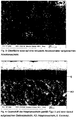
- FIG 2 shows a cross section of the anode structure coated with an electrolyte Figure 1 ,
- the multilayer electrolyte was applied to the anode structure by means of a PVD coating and consists of a CGO layer (E1), an 8YSZ layer (E2) and a further CGO layer (E3).
- E1 CGO layer
- E2 8YSZ layer
- E3 CGO layer
- the Figure 3 shows the surface structure of the adaptation layer applied to an anode structure. This is clearly recognizable in comparison with the anode structure Figure 1 significantly reduced pore size of the pores of the adaptation layer.
- the Figure 4 shows a cross section of the adaptation layer according to Figure 3 and an electrolyte applied thereon.
- the electrolyte is formed as a single layer of CGO and was applied using a PVD process. The growth of the electrolyte layer is undisturbed and homogeneous, so that the required gas tightness of the electrolyte is achieved.
- the roughness of the surface of this anode structure should be less than 3 ⁇ m, preferably less than 2 ⁇ m, for the square micro-center roughness value for the square mean roughness value R q R q ⁇ less than 1 ⁇ m, preferably less than 0.6 ⁇ m, and for the mean roughness depth R z less than 10 ⁇ m, preferably less than 6 ⁇ m, and for the mean microroughness depth R z ⁇ less than 4 microns, preferably less than 2 microns.
- the laser topograph CT200 (Cybertechnolgies GmbH, Ingolstadt) with a confocal laser sensor LT9010 was used to determine the roughness (measuring spot size approx. 2 ⁇ m, vertical resolution 10nm).
- At least three scanning electron micrographs of cross sections of the layers were evaluated for each parameter for the grain and pore sizes of the sintered structure determined using the line cutting method. 500-1,000 lines were drawn per image. With a number of pixels of the raster electronic recordings of 1024x768 pixels, a total section of the width of 5 to 15 ⁇ m was chosen for the adaptation layer.
- An 8YSZ powder with an average dispersible primary particle size of 150 nm and a specific surface area of 13 m 2 / g was used for the adaptation layer (TZ-8Y, Tosoh Corp., Japan).
- An immersion suspension was mixed with grinding balls with a diameter of 5 and 10 mm and homogenized on a roller bench for 48 hours, consisting of 67.2% by weight of solvent DBE (Dibasic ester, Lemro Chemical Products Michael Mrozyk KG, Grevenbroich), 30.5% by weight.
- % 8YSZ powder (TZ-8Y) and 2.3% by weight of ethyl cellulose as a binder (Fluka, 3-5.5 mPa s, Sigma-Aldrich Chemie GmbH, Kunststoff).
- the carrier substrates with the anode structure applied to them were immersed vertically in the suspension and, after a drying step in an H 2 atmosphere, sintered at 1200 ° C. for 3 hours.
- an adaptation layer thickness of 10 to 20 ⁇ m was obtained.
- the adaptation layer applied in this way had a square mean roughness value R q of 1.2 ⁇ m and an average roughness depth R z of 5.8 ⁇ m.
- the square micro-center roughness R q ⁇ showed a value of 0.21 ⁇ m and the average microroughness R z ⁇ showed a value of 0.67 ⁇ m.
- the gas tightness of this electrolyte was determined by means of a He leak test to be 3.4 ⁇ 10 -3 (hPa dm 3 ) / (s cm 2 ) for a pressure difference of 1000 hPa. This value corresponds to common anode-supported fuel cells in the reduced state.
Landscapes
- Chemical & Material Sciences (AREA)
- Engineering & Computer Science (AREA)
- Manufacturing & Machinery (AREA)
- Electrochemistry (AREA)
- General Chemical & Material Sciences (AREA)
- Chemical Kinetics & Catalysis (AREA)
- Life Sciences & Earth Sciences (AREA)
- Sustainable Development (AREA)
- Sustainable Energy (AREA)
- Materials Engineering (AREA)
- Composite Materials (AREA)
- Inert Electrodes (AREA)
- Fuel Cell (AREA)
Claims (13)
- Agencement d'une pile à combustible, comprenant- au moins une électrode (A, K), qui se présente sous forme réduite,- un électrolyte (E),- un substrat (8) support poreux métallique comme support de l'électrode (A, K) et de l'électrolyte,- une couche (AD) d'adaptation, qui est disposée entre l'électrode se présentant sous forme réduite et l'électrolyte, pour l'adaptation de l'électrolyte (E) à cette électrode (A, K),
caractérisé- en ce que la couche (AD) d'adaptation a une dimension de pore moyenne, qui est plus petite que la dimension de pore moyenne de l'électrode (A, K) se présentant sous forme réduite,
et- comprenant une couche (AD) d'adaptation en dioxyde de zirconium dopé, le dopage contenant au moins un oxyde des éléments de dopage choisis dans le groupe Y, Sc, Al, Sr, Ca, ou- comprenant une couche (AD) d'adaptation en oxyde de cérium dopé, le dopage contenant au moins un oxyde des éléments de dopage choisis dans le groupe des éléments de terre rare et/ou dans le groupe Y, Sc, Al, Sr, Ca,- dans lequel l'électrolyte est un électrolyte à couche mince étanche au gaz, dont l'épaisseur de couche est au maximum de 10 µm. - Agencement suivant la revendication 1, caractérisé en ce que la dimension de pore moyenne de la couche (AD) d'adaptation est au plus à moitié aussi grande que la dimension de pore moyenne de l'électrode (A, K)
- Agencement suivant la revendication 1 ou 2, caractérisé en ce que la dimension de pore moyenne de la couche (AD) d'adaptation est au plus de 500 nm, de préférence au plus de 350 nm.
- Agencement suivant l'une des revendications précédentes, caractérisé en ce que la couche (AD) d'adaptation a une rugosité Rq de surface moyenne plus petite que 2,5 µm, de préférence d'au plus 1,5 µm, d'une manière encore plus préférée d'au plus 1,0 µm.
- Agencement suivant l'une des revendications précédentes, caractérisé en ce que l'électrode est constituée en anode (A) .
- Agencement suivant l'une des revendications précédentes, caractérisé en ce que l'électrolyte (E) est disposé directement sur la surface, tournée vers l'électrolyte (E), de la couche (AD) d'adaptation.
- Agencement suivant l'une des revendications précédentes, caractérisé en ce que la couche (AD) d'adaptation a une épaisseur de 3 à 20 µm, de préférence de 3 à 7 µm.
- Agencement suivant l'une des revendications précédentes, caractérisé en ce que l'électrolyte (E) a une épaisseur de 0,2 à 10 µm, de préférence de 1 à 3 µm.
- Agencement suivant l'une des revendications précédentes, caractérisé par un électrolyte (E) en une matière ne conduisant pas des électrons.
- Agencement suivant la revendication 9, caractérisé par un électrolyte (E) en dioxyde de zirconium dopé, le dopage contenant au moins un oxyde des éléments de dopage choisis dans le groupe Y, Sc, Al, Sr, Ca.
- Agencement suivant l'une des revendications précédentes 1 à 8, caractérisé par un électrolyte (E) en une matière conduisant les électrons.
- Agencement suivant la revendication 11, caractérisé par un électrolyte (E) en oxyde de cérium dopé, le dopage contenant au moins un oxyde des éléments de dopage choisis dans le groupe des éléments de terre rare comme Gd, Sm et/ou choisis dans le groupe Y, Sc, Al, Sr, Ca.
- Procédé de production d'un agencement d'une pile à combustible suivant l'une des revendications 1 à 12, comprenant une électrode (A; K) et un électrolyte (E), caractérisé par les stades de procédé suivant :a) on se procure un substrat (8) de support poreux métallique comme support de l'électrode (A, K) et de l'électrolyte (E),b) on dépose l'électrode (A, K) sur le substrat (8) de support,c) on fritte la structure (A, K) d'électrode déposée sur le substrat (8) de support dans une atmosphère réductrice,d) on dépose une couche (AD) d'adaptation poreuse sur l'électrode (A, K) pour adapter l'électrolyte (E) à cet électrode (A, K), la dimension de pore moyenne de la couche (AD) d'adaptation étant plus petite que la dimension de pore moyenne de cette électrode (A, K) ete) on dépose l'électrolyte (E) sur la couche (AD) d'adaptation.
Priority Applications (1)
| Application Number | Priority Date | Filing Date | Title |
|---|---|---|---|
| EP10784263.5A EP2502296B1 (fr) | 2009-11-18 | 2010-11-17 | Agencement pour une cellula à combustible ainsi que son procédé de fabrication |
Applications Claiming Priority (3)
| Application Number | Priority Date | Filing Date | Title |
|---|---|---|---|
| EP09014400A EP2325931A1 (fr) | 2009-11-18 | 2009-11-18 | Agencement pour une cellule combustible ainsi que son procédé de fabrication |
| PCT/EP2010/007002 WO2011060928A1 (fr) | 2009-11-18 | 2010-11-17 | Système pour une pile à combustible ainsi que son procédé de fabrication |
| EP10784263.5A EP2502296B1 (fr) | 2009-11-18 | 2010-11-17 | Agencement pour une cellula à combustible ainsi que son procédé de fabrication |
Publications (2)
| Publication Number | Publication Date |
|---|---|
| EP2502296A1 EP2502296A1 (fr) | 2012-09-26 |
| EP2502296B1 true EP2502296B1 (fr) | 2020-02-12 |
Family
ID=42077208
Family Applications (2)
| Application Number | Title | Priority Date | Filing Date |
|---|---|---|---|
| EP09014400A Withdrawn EP2325931A1 (fr) | 2009-11-18 | 2009-11-18 | Agencement pour une cellule combustible ainsi que son procédé de fabrication |
| EP10784263.5A Active EP2502296B1 (fr) | 2009-11-18 | 2010-11-17 | Agencement pour une cellula à combustible ainsi que son procédé de fabrication |
Family Applications Before (1)
| Application Number | Title | Priority Date | Filing Date |
|---|---|---|---|
| EP09014400A Withdrawn EP2325931A1 (fr) | 2009-11-18 | 2009-11-18 | Agencement pour une cellule combustible ainsi que son procédé de fabrication |
Country Status (6)
| Country | Link |
|---|---|
| US (1) | US20130189606A1 (fr) |
| EP (2) | EP2325931A1 (fr) |
| JP (1) | JP5809159B2 (fr) |
| CA (1) | CA2781129A1 (fr) |
| TW (1) | TW201131875A (fr) |
| WO (1) | WO2011060928A1 (fr) |
Families Citing this family (7)
| Publication number | Priority date | Publication date | Assignee | Title |
|---|---|---|---|---|
| EP2640430B1 (fr) * | 2010-11-17 | 2016-03-09 | Zimmer, Inc. | Implants monoblocs en céramique à surfaces de fixation ostéo-intégrées |
| DE102011083541A1 (de) * | 2011-09-27 | 2013-03-28 | Siemens Aktiengesellschaft | Speicherelement |
| DE102013008472A1 (de) * | 2013-05-21 | 2014-11-27 | Plansee Composite Materials Gmbh | Mehrlagige Schichtanordnung für einen Festkörperelektrolyt |
| DE102015223704B4 (de) * | 2015-11-30 | 2018-10-25 | Robert Bosch Gmbh | Membranelektrodenanordnung und Verfahren zu ihrer Herstellung, Brennstoffzelle, Abgassonde und elektrochemisches Bauelement |
| JP6910170B2 (ja) * | 2017-03-22 | 2021-07-28 | 大阪瓦斯株式会社 | 金属支持型電気化学素子用の電極層付基板、電気化学素子、電気化学モジュール、電気化学装置、エネルギーシステム、固体酸化物形燃料電池、および製造方法 |
| JP6910171B2 (ja) * | 2017-03-22 | 2021-07-28 | 大阪瓦斯株式会社 | 電気化学素子の製造方法および電気化学素子 |
| KR102935447B1 (ko) * | 2020-02-04 | 2026-03-05 | 삼성전자주식회사 | 양극, 이를 포함하는 리튬-공기 전지 및 이의 제조 방법 |
Citations (1)
| Publication number | Priority date | Publication date | Assignee | Title |
|---|---|---|---|---|
| US20030157386A1 (en) * | 2002-02-20 | 2003-08-21 | Ion America Corporation | Load matched power generation system including a solid oxide fuel cell and a heat pump and an optional turbine |
Family Cites Families (15)
| Publication number | Priority date | Publication date | Assignee | Title |
|---|---|---|---|---|
| DE19626342A1 (de) * | 1996-07-01 | 1998-01-08 | Forschungszentrum Juelich Gmbh | Elektrodenzwischenschicht bei Brennstoffzellen |
| DE19819453A1 (de) * | 1998-04-30 | 1999-11-11 | Forschungszentrum Juelich Gmbh | SOFC-Brennstoffzelle mit einer Anodenzwischenschicht |
| DE10309968A1 (de) * | 2003-03-07 | 2004-09-23 | Forschungszentrum Jülich GmbH | Verfahren zur Herstellung eines Schichtsystems umfassend einen metallischen Träger und eine Anodenfunktionsschicht |
| DE10343652B4 (de) | 2003-09-20 | 2005-09-29 | Elringklinger Ag | Verfahren zum Herstellen einer Lötverbindung zwischen einem Substrat und einem Kontaktelement einer Brennstoffzelleneinheit sowie Brennstoffzelleneinheit |
| EP2259373A1 (fr) * | 2004-06-10 | 2010-12-08 | Technical University of Denmark | Pile à combustible d'oxyde solide |
| AU2005302387A1 (en) * | 2004-10-29 | 2006-05-11 | Franklin Fuel Cells, Inc | Electrochemical cell architecture and method of making same via controlled powder morphology |
| ES2292313B1 (es) * | 2005-09-27 | 2009-02-16 | Ikerlan, S. Coop. | Celda de combustible de oxido solido con soporte ferritico. |
| JP5179718B2 (ja) * | 2005-12-14 | 2013-04-10 | 日本特殊陶業株式会社 | 固体酸化物型燃料電池セル、固体酸化物型燃料電池スタック、及び固体酸化物型燃料電池セルの製造方法 |
| AT9543U1 (de) * | 2006-07-07 | 2007-11-15 | Plansee Se | Verfahren zur herstellung einer elektrisch leitfähigen schicht |
| JP4883364B2 (ja) * | 2007-03-23 | 2012-02-22 | 株式会社豊田中央研究所 | 多孔質支持体/水素選択透過膜基板及び多孔体支持型燃料電池 |
| DE102007015358A1 (de) | 2007-03-30 | 2008-10-02 | Forschungszentrum Jülich GmbH | Schichtsystem für einen Elektrolyten einer Hochtemperatur-Brennstoffzelle sowie Verfahren zur Herstellung desselben |
| JP5160131B2 (ja) * | 2007-04-06 | 2013-03-13 | 本田技研工業株式会社 | 電解質・電極接合体及びその製造方法 |
| WO2009005841A1 (fr) * | 2007-07-05 | 2009-01-08 | The Board Of Trustees Of The Leland Stanford Junior University | Interfaces électrode/électrolyte dans des piles à combustible à oxyde solide |
| WO2009064391A2 (fr) * | 2007-11-13 | 2009-05-22 | Bloom Energy Corporation | Pile supportée par un électrolyte conçue pour une durée de vie plus longue et pour délivrer une puissance plus élevée |
| US20110003084A1 (en) * | 2008-02-25 | 2011-01-06 | National Research Council Of Canada | Process of Making Ceria-Based Electrolyte Coating |
-
2009
- 2009-11-18 EP EP09014400A patent/EP2325931A1/fr not_active Withdrawn
-
2010
- 2010-11-12 TW TW099138966A patent/TW201131875A/zh unknown
- 2010-11-17 CA CA2781129A patent/CA2781129A1/fr not_active Abandoned
- 2010-11-17 US US13/510,080 patent/US20130189606A1/en not_active Abandoned
- 2010-11-17 EP EP10784263.5A patent/EP2502296B1/fr active Active
- 2010-11-17 JP JP2012539224A patent/JP5809159B2/ja not_active Expired - Fee Related
- 2010-11-17 WO PCT/EP2010/007002 patent/WO2011060928A1/fr not_active Ceased
Patent Citations (1)
| Publication number | Priority date | Publication date | Assignee | Title |
|---|---|---|---|---|
| US20030157386A1 (en) * | 2002-02-20 | 2003-08-21 | Ion America Corporation | Load matched power generation system including a solid oxide fuel cell and a heat pump and an optional turbine |
Also Published As
| Publication number | Publication date |
|---|---|
| WO2011060928A1 (fr) | 2011-05-26 |
| JP2013511799A (ja) | 2013-04-04 |
| TW201131875A (en) | 2011-09-16 |
| CA2781129A1 (fr) | 2011-05-26 |
| JP5809159B2 (ja) | 2015-11-10 |
| US20130189606A1 (en) | 2013-07-25 |
| EP2502296A1 (fr) | 2012-09-26 |
| WO2011060928A8 (fr) | 2012-10-11 |
| EP2325931A1 (fr) | 2011-05-25 |
Similar Documents
| Publication | Publication Date | Title |
|---|---|---|
| EP2502297B1 (fr) | Anode pour une cellule combustible haute température ainsi que son utilisation | |
| EP2676318B1 (fr) | Structure à empilement et son utilisation pour former une structure à empilement en ceramique entre un interconnecteur et une cathode d'une pile a combustible haute temperature | |
| DE69632531T2 (de) | Verbindungsvorrichtung für brennstoffzellen | |
| EP2502296B1 (fr) | Agencement pour une cellula à combustible ainsi que son procédé de fabrication | |
| DE19547700C2 (de) | Elektrodensubstrat für eine Brennstoffzelle | |
| DE4237602A1 (de) | Hochtemperatur-Brennstoffzellen-Stapel und Verfahren zu seiner Herstellung | |
| EP0788175A1 (fr) | Pile à combustible fonctionnant à haute température avec électrolyte à couche mince | |
| DE102006030393A1 (de) | Keramische Werkstoffkombination für eine Anode für eine Hochtemperatur-Brennstoffzelle | |
| EP3000149B1 (fr) | Ensemble multicouche pour électrolyte solide | |
| EP2654115B1 (fr) | Procédé de fabrication d'un substrat de support, substrat de support et dispositif électrochimique | |
| DE112023000202T5 (de) | Elektrochemische Zelle | |
| EP2669984B1 (fr) | Système de couches d'anode pour applications electrochimiques et son procédé de fabrication | |
| WO2010037681A1 (fr) | Pile à combustible plane à haute température | |
| DE102006056251B4 (de) | Hochtemperaturbrennstoffzelle mit ferritischer Komponente und Verfahren zum Betreiben derselben | |
| WO2013045230A1 (fr) | Procédé de fabrication d'une pile à combustible à électrolyte solide | |
| DE112024000074T5 (de) | Elektrochemische zelle | |
| DE112024000021T5 (de) | Elektrochemische zelle | |
| JP6837122B2 (ja) | 電気化学セル | |
| DE112023000198T5 (de) | Elektrochemische Zelle | |
| DE112023000197T5 (de) | Elektrochemische zelle | |
| DE102024209084A1 (de) | Verfahren zur Herstellung einer elektrochemischen Zelle, elektrochemische Zelle, elektrochemische Zellenvorrichtung | |
| DE112022006219T5 (de) | Elektrochemische Zelle | |
| DE9304984U1 (de) | Hochtemperatur-Brennstoffzellen-Stapel |
Legal Events
| Date | Code | Title | Description |
|---|---|---|---|
| PUAI | Public reference made under article 153(3) epc to a published international application that has entered the european phase |
Free format text: ORIGINAL CODE: 0009012 |
|
| 17P | Request for examination filed |
Effective date: 20120605 |
|
| AK | Designated contracting states |
Kind code of ref document: A1 Designated state(s): AL AT BE BG CH CY CZ DE DK EE ES FI FR GB GR HR HU IE IS IT LI LT LU LV MC MK MT NL NO PL PT RO RS SE SI SK SM TR |
|
| DAX | Request for extension of the european patent (deleted) | ||
| 17Q | First examination report despatched |
Effective date: 20141029 |
|
| STAA | Information on the status of an ep patent application or granted ep patent |
Free format text: STATUS: EXAMINATION IS IN PROGRESS |
|
| REG | Reference to a national code |
Ref country code: DE Ref legal event code: R079 Ref document number: 502010016485 Country of ref document: DE Free format text: PREVIOUS MAIN CLASS: H01M0004860000 Ipc: H01M0008121300 |
|
| RIC1 | Information provided on ipc code assigned before grant |
Ipc: H01M 4/86 20060101ALI20190717BHEP Ipc: H01M 8/126 20160101ALI20190717BHEP Ipc: H01M 8/1213 20160101AFI20190717BHEP Ipc: H01M 4/90 20060101ALI20190717BHEP Ipc: H01M 8/1246 20160101ALI20190717BHEP Ipc: H01M 4/88 20060101ALI20190717BHEP Ipc: H01M 8/1253 20160101ALI20190717BHEP |
|
| GRAP | Despatch of communication of intention to grant a patent |
Free format text: ORIGINAL CODE: EPIDOSNIGR1 |
|
| STAA | Information on the status of an ep patent application or granted ep patent |
Free format text: STATUS: GRANT OF PATENT IS INTENDED |
|
| INTG | Intention to grant announced |
Effective date: 20190905 |
|
| GRAS | Grant fee paid |
Free format text: ORIGINAL CODE: EPIDOSNIGR3 |
|
| GRAA | (expected) grant |
Free format text: ORIGINAL CODE: 0009210 |
|
| STAA | Information on the status of an ep patent application or granted ep patent |
Free format text: STATUS: THE PATENT HAS BEEN GRANTED |
|
| AK | Designated contracting states |
Kind code of ref document: B1 Designated state(s): AL AT BE BG CH CY CZ DE DK EE ES FI FR GB GR HR HU IE IS IT LI LT LU LV MC MK MT NL NO PL PT RO RS SE SI SK SM TR |
|
| REG | Reference to a national code |
Ref country code: GB Ref legal event code: FG4D Free format text: NOT ENGLISH |
|
| REG | Reference to a national code |
Ref country code: CH Ref legal event code: EP |
|
| REG | Reference to a national code |
Ref country code: AT Ref legal event code: REF Ref document number: 1233306 Country of ref document: AT Kind code of ref document: T Effective date: 20200215 |
|
| REG | Reference to a national code |
Ref country code: IE Ref legal event code: FG4D Free format text: LANGUAGE OF EP DOCUMENT: GERMAN |
|
| REG | Reference to a national code |
Ref country code: DE Ref legal event code: R096 Ref document number: 502010016485 Country of ref document: DE |
|
| PG25 | Lapsed in a contracting state [announced via postgrant information from national office to epo] |
Ref country code: RS Free format text: LAPSE BECAUSE OF FAILURE TO SUBMIT A TRANSLATION OF THE DESCRIPTION OR TO PAY THE FEE WITHIN THE PRESCRIBED TIME-LIMIT Effective date: 20200212 Ref country code: NO Free format text: LAPSE BECAUSE OF FAILURE TO SUBMIT A TRANSLATION OF THE DESCRIPTION OR TO PAY THE FEE WITHIN THE PRESCRIBED TIME-LIMIT Effective date: 20200512 Ref country code: FI Free format text: LAPSE BECAUSE OF FAILURE TO SUBMIT A TRANSLATION OF THE DESCRIPTION OR TO PAY THE FEE WITHIN THE PRESCRIBED TIME-LIMIT Effective date: 20200212 |
|
| REG | Reference to a national code |
Ref country code: LT Ref legal event code: MG4D |
|
| REG | Reference to a national code |
Ref country code: NL Ref legal event code: MP Effective date: 20200212 |
|
| PG25 | Lapsed in a contracting state [announced via postgrant information from national office to epo] |
Ref country code: SE Free format text: LAPSE BECAUSE OF FAILURE TO SUBMIT A TRANSLATION OF THE DESCRIPTION OR TO PAY THE FEE WITHIN THE PRESCRIBED TIME-LIMIT Effective date: 20200212 Ref country code: LV Free format text: LAPSE BECAUSE OF FAILURE TO SUBMIT A TRANSLATION OF THE DESCRIPTION OR TO PAY THE FEE WITHIN THE PRESCRIBED TIME-LIMIT Effective date: 20200212 Ref country code: IS Free format text: LAPSE BECAUSE OF FAILURE TO SUBMIT A TRANSLATION OF THE DESCRIPTION OR TO PAY THE FEE WITHIN THE PRESCRIBED TIME-LIMIT Effective date: 20200612 Ref country code: BG Free format text: LAPSE BECAUSE OF FAILURE TO SUBMIT A TRANSLATION OF THE DESCRIPTION OR TO PAY THE FEE WITHIN THE PRESCRIBED TIME-LIMIT Effective date: 20200512 Ref country code: HR Free format text: LAPSE BECAUSE OF FAILURE TO SUBMIT A TRANSLATION OF THE DESCRIPTION OR TO PAY THE FEE WITHIN THE PRESCRIBED TIME-LIMIT Effective date: 20200212 Ref country code: GR Free format text: LAPSE BECAUSE OF FAILURE TO SUBMIT A TRANSLATION OF THE DESCRIPTION OR TO PAY THE FEE WITHIN THE PRESCRIBED TIME-LIMIT Effective date: 20200513 |
|
| PG25 | Lapsed in a contracting state [announced via postgrant information from national office to epo] |
Ref country code: NL Free format text: LAPSE BECAUSE OF FAILURE TO SUBMIT A TRANSLATION OF THE DESCRIPTION OR TO PAY THE FEE WITHIN THE PRESCRIBED TIME-LIMIT Effective date: 20200212 |
|
| PG25 | Lapsed in a contracting state [announced via postgrant information from national office to epo] |
Ref country code: EE Free format text: LAPSE BECAUSE OF FAILURE TO SUBMIT A TRANSLATION OF THE DESCRIPTION OR TO PAY THE FEE WITHIN THE PRESCRIBED TIME-LIMIT Effective date: 20200212 Ref country code: LT Free format text: LAPSE BECAUSE OF FAILURE TO SUBMIT A TRANSLATION OF THE DESCRIPTION OR TO PAY THE FEE WITHIN THE PRESCRIBED TIME-LIMIT Effective date: 20200212 Ref country code: DK Free format text: LAPSE BECAUSE OF FAILURE TO SUBMIT A TRANSLATION OF THE DESCRIPTION OR TO PAY THE FEE WITHIN THE PRESCRIBED TIME-LIMIT Effective date: 20200212 Ref country code: SK Free format text: LAPSE BECAUSE OF FAILURE TO SUBMIT A TRANSLATION OF THE DESCRIPTION OR TO PAY THE FEE WITHIN THE PRESCRIBED TIME-LIMIT Effective date: 20200212 Ref country code: PT Free format text: LAPSE BECAUSE OF FAILURE TO SUBMIT A TRANSLATION OF THE DESCRIPTION OR TO PAY THE FEE WITHIN THE PRESCRIBED TIME-LIMIT Effective date: 20200705 Ref country code: CZ Free format text: LAPSE BECAUSE OF FAILURE TO SUBMIT A TRANSLATION OF THE DESCRIPTION OR TO PAY THE FEE WITHIN THE PRESCRIBED TIME-LIMIT Effective date: 20200212 Ref country code: ES Free format text: LAPSE BECAUSE OF FAILURE TO SUBMIT A TRANSLATION OF THE DESCRIPTION OR TO PAY THE FEE WITHIN THE PRESCRIBED TIME-LIMIT Effective date: 20200212 Ref country code: RO Free format text: LAPSE BECAUSE OF FAILURE TO SUBMIT A TRANSLATION OF THE DESCRIPTION OR TO PAY THE FEE WITHIN THE PRESCRIBED TIME-LIMIT Effective date: 20200212 Ref country code: SM Free format text: LAPSE BECAUSE OF FAILURE TO SUBMIT A TRANSLATION OF THE DESCRIPTION OR TO PAY THE FEE WITHIN THE PRESCRIBED TIME-LIMIT Effective date: 20200212 |
|
| REG | Reference to a national code |
Ref country code: DE Ref legal event code: R097 Ref document number: 502010016485 Country of ref document: DE |
|
| PLBE | No opposition filed within time limit |
Free format text: ORIGINAL CODE: 0009261 |
|
| STAA | Information on the status of an ep patent application or granted ep patent |
Free format text: STATUS: NO OPPOSITION FILED WITHIN TIME LIMIT |
|
| 26N | No opposition filed |
Effective date: 20201113 |
|
| PG25 | Lapsed in a contracting state [announced via postgrant information from national office to epo] |
Ref country code: IT Free format text: LAPSE BECAUSE OF FAILURE TO SUBMIT A TRANSLATION OF THE DESCRIPTION OR TO PAY THE FEE WITHIN THE PRESCRIBED TIME-LIMIT Effective date: 20200212 |
|
| PG25 | Lapsed in a contracting state [announced via postgrant information from national office to epo] |
Ref country code: SI Free format text: LAPSE BECAUSE OF FAILURE TO SUBMIT A TRANSLATION OF THE DESCRIPTION OR TO PAY THE FEE WITHIN THE PRESCRIBED TIME-LIMIT Effective date: 20200212 Ref country code: PL Free format text: LAPSE BECAUSE OF FAILURE TO SUBMIT A TRANSLATION OF THE DESCRIPTION OR TO PAY THE FEE WITHIN THE PRESCRIBED TIME-LIMIT Effective date: 20200212 |
|
| PG25 | Lapsed in a contracting state [announced via postgrant information from national office to epo] |
Ref country code: MC Free format text: LAPSE BECAUSE OF FAILURE TO SUBMIT A TRANSLATION OF THE DESCRIPTION OR TO PAY THE FEE WITHIN THE PRESCRIBED TIME-LIMIT Effective date: 20200212 |
|
| GBPC | Gb: european patent ceased through non-payment of renewal fee |
Effective date: 20201117 |
|
| PG25 | Lapsed in a contracting state [announced via postgrant information from national office to epo] |
Ref country code: LU Free format text: LAPSE BECAUSE OF NON-PAYMENT OF DUE FEES Effective date: 20201117 |
|
| REG | Reference to a national code |
Ref country code: BE Ref legal event code: MM Effective date: 20201130 |
|
| PG25 | Lapsed in a contracting state [announced via postgrant information from national office to epo] |
Ref country code: FR Free format text: LAPSE BECAUSE OF NON-PAYMENT OF DUE FEES Effective date: 20201130 Ref country code: IE Free format text: LAPSE BECAUSE OF NON-PAYMENT OF DUE FEES Effective date: 20201117 |
|
| PG25 | Lapsed in a contracting state [announced via postgrant information from national office to epo] |
Ref country code: GB Free format text: LAPSE BECAUSE OF NON-PAYMENT OF DUE FEES Effective date: 20201117 |
|
| PGFP | Annual fee paid to national office [announced via postgrant information from national office to epo] |
Ref country code: AT Payment date: 20211117 Year of fee payment: 12 Ref country code: DE Payment date: 20211005 Year of fee payment: 12 |
|
| PGFP | Annual fee paid to national office [announced via postgrant information from national office to epo] |
Ref country code: CH Payment date: 20211123 Year of fee payment: 12 |
|
| PG25 | Lapsed in a contracting state [announced via postgrant information from national office to epo] |
Ref country code: TR Free format text: LAPSE BECAUSE OF FAILURE TO SUBMIT A TRANSLATION OF THE DESCRIPTION OR TO PAY THE FEE WITHIN THE PRESCRIBED TIME-LIMIT Effective date: 20200212 Ref country code: MT Free format text: LAPSE BECAUSE OF FAILURE TO SUBMIT A TRANSLATION OF THE DESCRIPTION OR TO PAY THE FEE WITHIN THE PRESCRIBED TIME-LIMIT Effective date: 20200212 Ref country code: CY Free format text: LAPSE BECAUSE OF FAILURE TO SUBMIT A TRANSLATION OF THE DESCRIPTION OR TO PAY THE FEE WITHIN THE PRESCRIBED TIME-LIMIT Effective date: 20200212 |
|
| PG25 | Lapsed in a contracting state [announced via postgrant information from national office to epo] |
Ref country code: MK Free format text: LAPSE BECAUSE OF FAILURE TO SUBMIT A TRANSLATION OF THE DESCRIPTION OR TO PAY THE FEE WITHIN THE PRESCRIBED TIME-LIMIT Effective date: 20200212 Ref country code: AL Free format text: LAPSE BECAUSE OF FAILURE TO SUBMIT A TRANSLATION OF THE DESCRIPTION OR TO PAY THE FEE WITHIN THE PRESCRIBED TIME-LIMIT Effective date: 20200212 |
|
| PG25 | Lapsed in a contracting state [announced via postgrant information from national office to epo] |
Ref country code: BE Free format text: LAPSE BECAUSE OF NON-PAYMENT OF DUE FEES Effective date: 20201130 |
|
| REG | Reference to a national code |
Ref country code: DE Ref legal event code: R119 Ref document number: 502010016485 Country of ref document: DE |
|
| REG | Reference to a national code |
Ref country code: CH Ref legal event code: PL |
|
| REG | Reference to a national code |
Ref country code: AT Ref legal event code: MM01 Ref document number: 1233306 Country of ref document: AT Kind code of ref document: T Effective date: 20221117 |
|
| PG25 | Lapsed in a contracting state [announced via postgrant information from national office to epo] |
Ref country code: LI Free format text: LAPSE BECAUSE OF NON-PAYMENT OF DUE FEES Effective date: 20221130 Ref country code: CH Free format text: LAPSE BECAUSE OF NON-PAYMENT OF DUE FEES Effective date: 20221130 Ref country code: AT Free format text: LAPSE BECAUSE OF NON-PAYMENT OF DUE FEES Effective date: 20221117 |
|
| PG25 | Lapsed in a contracting state [announced via postgrant information from national office to epo] |
Ref country code: DE Free format text: LAPSE BECAUSE OF NON-PAYMENT OF DUE FEES Effective date: 20230601 |