EP2502549A1 - Endoscope apparatus - Google Patents
Endoscope apparatus Download PDFInfo
- Publication number
- EP2502549A1 EP2502549A1 EP12158989A EP12158989A EP2502549A1 EP 2502549 A1 EP2502549 A1 EP 2502549A1 EP 12158989 A EP12158989 A EP 12158989A EP 12158989 A EP12158989 A EP 12158989A EP 2502549 A1 EP2502549 A1 EP 2502549A1
- Authority
- EP
- European Patent Office
- Prior art keywords
- light
- output
- diffusing
- endoscope apparatus
- special
- Prior art date
- Legal status (The legal status is an assumption and is not a legal conclusion. Google has not performed a legal analysis and makes no representation as to the accuracy of the status listed.)
- Withdrawn
Links
- 238000003780 insertion Methods 0.000 claims abstract description 97
- 230000037431 insertion Effects 0.000 claims abstract description 97
- 239000013307 optical fiber Substances 0.000 claims description 48
- 238000009792 diffusion process Methods 0.000 claims description 26
- 239000007788 liquid Substances 0.000 claims description 14
- 239000011347 resin Substances 0.000 claims description 4
- 229920005989 resin Polymers 0.000 claims description 4
- 230000005284 excitation Effects 0.000 abstract description 54
- 238000003384 imaging method Methods 0.000 description 64
- 238000002073 fluorescence micrograph Methods 0.000 description 37
- 238000000034 method Methods 0.000 description 20
- 230000005540 biological transmission Effects 0.000 description 11
- 230000003287 optical effect Effects 0.000 description 9
- 238000010586 diagram Methods 0.000 description 6
- MOFVSTNWEDAEEK-UHFFFAOYSA-M indocyanine green Chemical compound [Na+].[O-]S(=O)(=O)CCCCN1C2=CC=C3C=CC=CC3=C2C(C)(C)C1=CC=CC=CC=CC1=[N+](CCCCS([O-])(=O)=O)C2=CC=C(C=CC=C3)C3=C2C1(C)C MOFVSTNWEDAEEK-UHFFFAOYSA-M 0.000 description 6
- 229960004657 indocyanine green Drugs 0.000 description 6
- 230000000694 effects Effects 0.000 description 5
- 238000009825 accumulation Methods 0.000 description 4
- 238000006243 chemical reaction Methods 0.000 description 3
- 230000002596 correlated effect Effects 0.000 description 3
- 239000000463 material Substances 0.000 description 3
- 238000005070 sampling Methods 0.000 description 3
- 230000003247 decreasing effect Effects 0.000 description 2
- 210000002751 lymph Anatomy 0.000 description 2
- 238000003825 pressing Methods 0.000 description 2
- 210000001519 tissue Anatomy 0.000 description 2
- XLYOFNOQVPJJNP-UHFFFAOYSA-N water Substances O XLYOFNOQVPJJNP-UHFFFAOYSA-N 0.000 description 2
- 229920006311 Urethane elastomer Polymers 0.000 description 1
- 210000000941 bile Anatomy 0.000 description 1
- 210000003445 biliary tract Anatomy 0.000 description 1
- 230000017531 blood circulation Effects 0.000 description 1
- 210000004204 blood vessel Anatomy 0.000 description 1
- 239000003086 colorant Substances 0.000 description 1
- 230000006870 function Effects 0.000 description 1
- 238000005286 illumination Methods 0.000 description 1
- 239000003921 oil Substances 0.000 description 1
- 239000000049 pigment Substances 0.000 description 1
- 230000035945 sensitivity Effects 0.000 description 1
- 238000007493 shaping process Methods 0.000 description 1
- 239000002210 silicon-based material Substances 0.000 description 1
- 230000003595 spectral effect Effects 0.000 description 1
- 229910052724 xenon Inorganic materials 0.000 description 1
- FHNFHKCVQCLJFQ-UHFFFAOYSA-N xenon atom Chemical compound [Xe] FHNFHKCVQCLJFQ-UHFFFAOYSA-N 0.000 description 1
Images




Classifications
-
- A—HUMAN NECESSITIES
- A61—MEDICAL OR VETERINARY SCIENCE; HYGIENE
- A61B—DIAGNOSIS; SURGERY; IDENTIFICATION
- A61B1/00—Instruments for performing medical examinations of the interior of cavities or tubes of the body by visual or photographical inspection, e.g. endoscopes; Illuminating arrangements therefor
- A61B1/00112—Connection or coupling means
- A61B1/00121—Connectors, fasteners and adapters, e.g. on the endoscope handle
- A61B1/00126—Connectors, fasteners and adapters, e.g. on the endoscope handle optical, e.g. for light supply cables
-
- A—HUMAN NECESSITIES
- A61—MEDICAL OR VETERINARY SCIENCE; HYGIENE
- A61B—DIAGNOSIS; SURGERY; IDENTIFICATION
- A61B1/00—Instruments for performing medical examinations of the interior of cavities or tubes of the body by visual or photographical inspection, e.g. endoscopes; Illuminating arrangements therefor
- A61B1/00112—Connection or coupling means
- A61B1/00117—Optical cables in or with an endoscope
-
- A—HUMAN NECESSITIES
- A61—MEDICAL OR VETERINARY SCIENCE; HYGIENE
- A61B—DIAGNOSIS; SURGERY; IDENTIFICATION
- A61B1/00—Instruments for performing medical examinations of the interior of cavities or tubes of the body by visual or photographical inspection, e.g. endoscopes; Illuminating arrangements therefor
- A61B1/00163—Optical arrangements
- A61B1/00165—Optical arrangements with light-conductive means, e.g. fibre optics
-
- A—HUMAN NECESSITIES
- A61—MEDICAL OR VETERINARY SCIENCE; HYGIENE
- A61B—DIAGNOSIS; SURGERY; IDENTIFICATION
- A61B1/00—Instruments for performing medical examinations of the interior of cavities or tubes of the body by visual or photographical inspection, e.g. endoscopes; Illuminating arrangements therefor
- A61B1/06—Instruments for performing medical examinations of the interior of cavities or tubes of the body by visual or photographical inspection, e.g. endoscopes; Illuminating arrangements therefor with illuminating arrangements
- A61B1/0638—Instruments for performing medical examinations of the interior of cavities or tubes of the body by visual or photographical inspection, e.g. endoscopes; Illuminating arrangements therefor with illuminating arrangements providing two or more wavelengths
-
- A—HUMAN NECESSITIES
- A61—MEDICAL OR VETERINARY SCIENCE; HYGIENE
- A61B—DIAGNOSIS; SURGERY; IDENTIFICATION
- A61B1/00—Instruments for performing medical examinations of the interior of cavities or tubes of the body by visual or photographical inspection, e.g. endoscopes; Illuminating arrangements therefor
- A61B1/06—Instruments for performing medical examinations of the interior of cavities or tubes of the body by visual or photographical inspection, e.g. endoscopes; Illuminating arrangements therefor with illuminating arrangements
- A61B1/0661—Endoscope light sources
- A61B1/0669—Endoscope light sources at proximal end of an endoscope
-
- A—HUMAN NECESSITIES
- A61—MEDICAL OR VETERINARY SCIENCE; HYGIENE
- A61B—DIAGNOSIS; SURGERY; IDENTIFICATION
- A61B1/00—Instruments for performing medical examinations of the interior of cavities or tubes of the body by visual or photographical inspection, e.g. endoscopes; Illuminating arrangements therefor
- A61B1/06—Instruments for performing medical examinations of the interior of cavities or tubes of the body by visual or photographical inspection, e.g. endoscopes; Illuminating arrangements therefor with illuminating arrangements
- A61B1/07—Instruments for performing medical examinations of the interior of cavities or tubes of the body by visual or photographical inspection, e.g. endoscopes; Illuminating arrangements therefor with illuminating arrangements using light-conductive means, e.g. optical fibres
-
- G—PHYSICS
- G02—OPTICS
- G02B—OPTICAL ELEMENTS, SYSTEMS OR APPARATUS
- G02B23/00—Telescopes, e.g. binoculars; Periscopes; Instruments for viewing the inside of hollow bodies; Viewfinders; Optical aiming or sighting devices
- G02B23/24—Instruments or systems for viewing the inside of hollow bodies, e.g. fibrescopes
- G02B23/2407—Optical details
- G02B23/2461—Illumination
- G02B23/2469—Illumination using optical fibres
-
- G—PHYSICS
- G02—OPTICS
- G02B—OPTICAL ELEMENTS, SYSTEMS OR APPARATUS
- G02B6/00—Light guides; Structural details of arrangements comprising light guides and other optical elements, e.g. couplings
- G02B6/24—Coupling light guides
- G02B6/36—Mechanical coupling means
- G02B6/40—Mechanical coupling means having fibre bundle mating means
-
- G—PHYSICS
- G02—OPTICS
- G02B—OPTICAL ELEMENTS, SYSTEMS OR APPARATUS
- G02B6/00—Light guides; Structural details of arrangements comprising light guides and other optical elements, e.g. couplings
- G02B6/24—Coupling light guides
- G02B6/26—Optical coupling means
- G02B6/264—Optical coupling means with optical elements between opposed fibre ends which perform a function other than beam splitting
Definitions
- an endoscope system which observes tissue inside a body cavity has been widely known, and an electronic endoscope system which captures an ordinary image of a subject observation portion inside a body cavity by the irradiation of white light, acquires an ordinary image, and displays the ordinary image on a monitor screen has been widely put to practical use.
- an endoscope system which inputs ICG (indocyanine green) into a subject observation portion in advance and then irradiates excitation light of near-infrared light to the subject observation portion to acquire a fluorescence image of ICG for the purpose of observing blood vessels and blood flow under fat, lymph vessels, lymph flow, biliary tracts, bile flow and the like which do not show up on an ordinary image.
- ICG indocyanine green
- JP2003-153850A proposes a system that uses a rigid scope that is inserted into a body cavity.
- JP2003-153850A proposes a rigid scope system in which excitation light output from a light source device is supplied to a rigid scope body through a light guide connected to the light source device.
- the light guide and the rigid scope body are attachable to and detachable from each other.
- it is dangerous if the light source device is accidentally left in a state where excitation light is being output when attaching the light guide to the rigid scope body or detaching the light guide from the rigid scope body after operation, because excitation light output from the connection portion of the light guide may enter the eye.
- the present invention has been made in view of the above-mentioned problems and an object of the present invention is to provide an endoscope apparatus capable of preventing excitation light output from a connection portion of a light guide from entering and thereby damaging the eye when the light guide is detached.
- an endoscope apparatus including: an insertion portion that is inserted into a body so as to irradiate special light to a subject observation portion inside the body and receives light output from the subject observation portion by the irradiation of the special light; and a light guiding portion that is optically connected to the insertion portion and guides the special light output from a light source to the insertion portion.
- An output end for the special light in the light guiding portion is equipped with a diffusing portion that diffuses the special light guided by the light guiding portion.
- near-infrared light may be used as the special light.
- a diffusing portion in which a diffusion surface diffusing the special light in the diffusing portion faces the output end of the light guiding portion may be provided.
- a transmissive member which has the same refractive index as that of the light guiding portion and through which the special light output from the light guiding portion is transmitted may be installed between the diffusing portion and the input end for the special light in the insertion portion. Furthermore, 'the same refractive index as that of the light guiding portion' indicates the same or almost the same refractive index and a refractive index that is almost identical can be appropriately selected by a user of the special light.
- transmissive member with elasticity may be used as the transmissive member.
- transmissive member formed of a resin may be used as the transmissive member.
- the transmissive member may be detachably installed at the output end of the light guiding portion or the input end of the insertion portion.
- a supply member which supplies a liquid or a gel with the same refractive index as that of the light guiding portion may be installed between the diffusing portion and the input end for the special light in the insertion portion, and the supply member may be detachably installed at the output end of the light guiding portion or the input end of the insertion portion.
- a diffusing portion in which the diffusion surface diffusing the special light in the diffusing portion faces the input end of the insertion portion may be provided.
- a lens diffusing plate may be used as the diffusing portion.
- the insertion portion may include an optical fiber into which the special light output from the light guiding portion is input and which guides the input special light, and the input end portion for the special light in the optical fiber may be formed in a taper shape in which the core diameter increases toward the output end of the light guiding portion.
- the light guiding portion may also guide white light output from a white light source along with the special light, and the insertion portion may irradiate the white light guided by the light guiding portion to the subject observation portion.
- an endoscope apparatus includes: an insertion portion that is inserted into a body so as to irradiate special light to a subject observation portion inside the body and receives light output from the subject observation portion by the irradiation of the special light; and a light guiding portion that is optically connected to the insertion portion and guides the special light output from a light source to the insertion portion.
- An output end for the special light in the light guiding portion is equipped with a diffusing portion that diffuses the special light guided by the light guiding portion. Accordingly, it is possible to prevent excitation light output from the output end of the light guiding portion from entering and thereby damaging the eye when the light guiding portion is detached from the insertion portion.
- the endoscope apparatus of the present invention in a state where the light guiding portion is connected to the insertion portion, when a transmissive member which has the same refractive index as that of the light guiding portion and through which the special light output from the light guiding portion is transmitted is installed between the diffusing portion and the input end for the special light in the insertion portion, the special light transmission efficiency between the light guiding portion and the insertion portion may be improved.
- the diffusing effect may be suppressed by the diffusion surface of the diffusing portion coming into close contact with the transmissive member, the special light transmission efficiency may be further improved.
- the special light transmission efficiency between the light guiding portion and the insertion portion may be improved.
- the supply member when the supply member is detachably installed at the output end of the light guiding portion or the input end of the insertion portion, the supply member may be disposable.
- the diffusing portion in which the diffusion surface faces the input end surface of the insertion portion when the diffusing portion in which the diffusion surface faces the input end surface of the insertion portion is provided, the diffusing effect may be suppressed in a manner such that the diffusion surface of the diffusing portion contacts the liquid or the gel, and hence the special light transmission efficiency may be improved.
- the optical fiber which guides the special light when installed inside the insertion portion and the input end portion for the special light in the optical fiber has a taper shape in which the core diameter increases toward the output end of the light guiding portion, the special light condensing efficiency may be improved. Furthermore, when the core area of the output end of the optical fiber is set to be smaller than the core area of the input end of the optical fiber, the diffusion angle of the light output from the output end may be widened by the conservation rule of Etendue, and hence the special light irradiation range with respect to the subject observation portion may be widened.
- Fig. 1 is a schematic configuration diagram illustrating a rigid scope system that uses an embodiment of an endoscope apparatus of the present invention.
- Fig. 2 is a schematic configuration diagram illustrating a body cavity insertion portion.
- Fig. 3 is a cross-sectional view illustrating a configuration of a light guide.
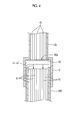
- Fig. 4 is a cross-sectional view illustrating a state where the light guide and an insertion member are connected to each other.
- Fig. 5 is a schematic configuration diagram illustrating an imaging unit.
- Fig. 6 is a block diagram illustrating a schematic configuration of an image processing apparatus and a light source device.
- Fig. 7 is a cross-sectional view illustrating another embodiment of a multi-mode optical fiber installed inside the insertion member.
- Fig. 8 is a cross-sectional view illustrating an embodiment when a transmissive member is installed between an output end of the multi-mode optical fiber of the light guide and the multi-mode optical fiber of the insertion member.
- Fig. 9 is a cross-sectional view illustrating an embodiment in which a supply member is installed between the light guide and a cable connection portion of the insertion member.
- Fig. 1 is an external diagram illustrating a schematic configuration of a rigid scope system 1 of the embodiment.
- a rigid scope system 1 of the embodiment includes: a light source device 2 which outputs white ordinary light and excitation light (special light); a rigid scope imaging device 10 which irradiates a subject observation portion by guiding the ordinary light and the excitation light output from the light source device 2 and captures an ordinary image based on reflection light reflected from the subject observation portion by the irradiation of the ordinary light and a fluorescence image based on fluorescence output from the subject observation portion by the irradiation of the excitation light; a processor 3 which applies a predetermined process to an image signal captured by the rigid scope imaging device 10; and a monitor 4 which displays the ordinary image and the fluorescence image of the subject observation portion based on the display control signal generated in the processor 3.
- a light source device 2 which outputs white ordinary light and excitation light (special light)
- a rigid scope imaging device 10 which irradiates a subject observation portion by guiding the ordinary light and the excitation light output from the light source device 2 and captures an ordinary image based on
- the rigid scope imaging device 10 includes a body cavity insertion portion 30 (an insertion portion) which is inserted into a body cavity and an imaging unit 20 which captures the ordinary image and the fluorescence image of the subject observation portion using the light guided by the body cavity insertion portion 30.
- the body cavity insertion portion 30 and the imaging unit 20 are detachably connected to each other.
- the body cavity insertion portion 30 includes a connection member 30a, an insertion member 30b, a cable connection portion 30c, and an irradiation window 30d.
- connection member 30a is installed at one end portion 30X, the imaging unit 20 side, of the body cavity insertion portion 30 (the insertion member 30b).
- the imaging unit 20 and the body cavity insertion portion 30 are detachably connected to each other by the connection member 30a being fitted into an opening 20a formed in the imaging unit 20.
- the insertion member 30b is inserted into a body cavity when image capture inside the body cavity is performed and thus is formed of a rigid material and has, for example, a cylindrical shape with a diameter of approximately 5 mm.
- a lens group which forms the image of the subject observation portion is accommodated, and a multi-mode optical fiber 31 which guides the ordinary light and the excitation light to the distal end of the insertion member 30b is bundled and extended, The details of the multi-mode optical fiber 31 will be described later.
- the ordinary light and the excitation light which are input to the insertion member 30b are guided by the bundled multi-mode optical fiber 31, and are irradiated from a distal end portion 30Y toward the subject observation portion. Then, the ordinary image and the fluorescence image which are output from the subject observation portion by the irradiation of the ordinary light and the excitation light are input from the distal end portion 30Y, and are output from an end portion 30X, the imaging unit 20 side, through the above-described lens group.
- the cable connection portion 30c is equipped on the side surface of the insertion member 30b ,and the light guide LG (the light guiding portion) is mechanically connected to the cable connection portion 30c through a connector C. Accordingly, the light source device 2 and the insertion member 30b are optically connected to each other through the light guide LG
- the ordinary light and the excitation light are input from one end thereof, and a multi-mode optical fiber 61 which guides the input ordinary light and the input excitation light is bundled and extended.
- the output end portion for the ordinary light and the excitation light in the multi-mode optical fiber 61 is equipped with the connector C which is fitted and connected to the cable connection portion 30c of the insertion member 30b, and the inside of the connector C is equipped with a diffusing portion 60 which is optically connected to the output end surface of the multi-mode optical fiber 61.
- a diffusing portion 60 for example, a lens diffusing plate (LSD: Light shaping Diffusers), a diffusing film, a diffusing sheet, a diffusing filter, and the like may be used. That is, the diffusing portion may be formed as any type through which input light is transmitted in a diffusing manner.
- the diffusing portion 60 when a lens diffusing plate is used as the diffusing portion 60, as shown in Fig. 3 , it is desirable to install the lens diffusing plate so that the diffusion surface 60a having a surface-relief-hologram pattern formed thereon becomes the input surface for the ordinary light and the excitation light, that is, the diffusion surface 60a becomes the light output end surface of the multi-mode optical fiber 61. Since the diffusion surface 60a is disposed in the above-described direction, it is possible to prevent a problem in which dirt or water adheres to the diffusion surface so that the diffusing function degrades.
- Fig. 4 illustrates a state where the connector C of the light guide LG is connected to the cable connection portion 30c of the insertion member 30b.
- a gap is formed between the light output surface of the diffusing portion 60 and the light input surface of the multi-mode optical fiber 31 installed inside the insertion member 30b in a state where the light guide LG is connected to the insertion member 30b. Accordingly, it is possible to prevent the diffusing portion 60 and the multi-mode optical fiber 31 from being damaged by a collision therebetween.
- the ordinary light L1 and the excitation light L2 which are guided by the multi-mode optical fiber 61 inside the light guide LG are input to the diffusing portion 60, diffused in the diffusion surface 60a of the diffusing portion 60, and after being output are input from the input surface of the multi-mode optical fiber 31 installed inside the insertion member 30b.
- the distal end portion 30Y of the insertion member 30b is equipped with an irradiation window 30d as shown in Fig. 2 .
- the irradiation window 30d irradiates the ordinary light and the excitation light which are guided by the multi-mode optical fiber 31 extending inside the insertion member 30b to the subject observation portion.
- Fig. 5 is a diagram illustrating a schematic configuration of the imaging unit 20.
- the imaging unit 20 includes a first imaging system which generates a fluorescence image signal of the subject observation portion by capturing the fluorescence image of the subject observation portion formed by the lens group inside the body cavity insertion portion 30 and a second imaging system which generates an ordinary image signal by capturing the ordinary image of the subject observation portion formed by the lens group inside the body cavity insertion portion 30.
- These imaging systems are divided into two optical axes perpendicular to each other by dichroic prisms 21 which have spectral characteristics which reflect the ordinary image and cause the fluorescence image to be transmitted therethrough.
- the first imaging system includes an excitation light cut-off filter 22, a first imaging optical system 23 and a high-sensitive imaging element 24.
- the excitation light cut-off filter 22 cuts light at a wavelength lower than that of the excitation light reflected from the subject observation portion and transmitted through the dichroic prism 21, and causes fluorescence wavelength band illumination light to be described later to be transmitted therethrough.
- the first imaging optical system 23 forms a fluorescence image L4 output from the body cavity insertion portion 30 and transmitted through the dichroic prism 21 and the excitation light cut-off filter 22.
- the high-sensitive imaging element 24 captures the fluorescence image L4 formed by the first imaging optical system 23.
- the high-sensitive imaging element 24 has a high sensitivity for detecting light of the wavelength band of the fluorescence image L4 and converts it into a fluorescence image signal and outputs this signal.
- a monochrome imaging element may be used as the high-sensitive imaging element 24.
- the second imaging system includes a second imaging optical system 25 and an imaging element 26.
- the second imaging optical system 25 forms ordinary image L3 output from the body cavity insertion portion 30 and reflected from the dichroic prism 21.
- the imaging element 26 captures an ordinary image L3 formed by the second imaging optical system 25.
- the imaging element 26 detects light of the wavelength band of the ordinary image, converts it into an ordinary image signal and outputs this signal.
- color filters of three primary colors, red (R), green (G), and blue (B), or cyan (C), magenta (M), and yellow (Y) are arranged according to a Bayer arrangement or a honeycomb arrangement.
- the imaging unit 20 includes an imaging control unit 27.
- the imaging control unit 27 performs a CDS/AGC (correlated double sampling/automatic gain control) process or an A/D conversion process on the fluorescence image signal output from the high-sensitive imaging element 24 and the ordinary image signal output from the imaging element 26, and outputs the result to the processor 3 through the cable 5 (see Fig. 1 ).
- CDS/AGC correlated double sampling/automatic gain control
- A/D conversion process on the fluorescence image signal output from the high-sensitive imaging element 24 and the ordinary image signal output from the imaging element 26, and outputs the result to the processor 3 through the cable 5 (see Fig. 1 ).
- the processor 3 includes an ordinary image input controller 41, a fluorescence image input controller 42, an image process section 43, a memory 44, a video output section 45, an operation section 46, a TG (a timing generator) 47, and a CPU 48.
- the ordinary image input controller 41 and the fluorescence image input controller 42 include a line buffer with a predetermined capacity, and the ordinary image input controller 41 temporarily stores the ordinary image signal for each frame output from the imaging control unit 27 of the imaging unit 20, and the fluorescence image input controller 42 temporarily stores the fluorescence image signal. Then, the ordinary image signal stored in the ordinary image input controller 41 and the fluorescence image signal stored in the fluorescence image input controller 42 are stored in the memory 44 through a bus.
- the image process section 43 receives the ordinary image signal and the fluorescence image signal for each frame read out from the memory 44, performs a predetermined image process on the image signals, and outputs the result to the bus.
- the video output section 45 receives the ordinary image signal and the fluorescence image signal output from the image process section 43 through the bus, performs a predetermined process thereon so as to generate a display control signal, and outputs the display control signal to the monitor 4.
- the operation section 46 receives an input from an operator, such as various operation instructions or control parameters. Further, the TG 47 outputs driving pulses for driving the high-sensitive imaging element 24 of the imaging unit 20, the imaging element 26, and the LD driver 55 of the light source device 2 to be described later. Further, the CPU 48 controls the entire apparatus.
- the light source device 2 includes: an ordinary light source 50 which outputs the ordinary light (white light) L1 and is formed by a wide band wavelength of about 400 to 700 nm; a condenser lens 52 which condenses the ordinary light L1 output from the ordinary light source 50; and a dichroic mirror 53 through which the ordinary light L1 condensed by the condenser lens 52 is transmitted and which reflects the excitation light L2 to be described later so that the ordinary light L1 and the excitation light L2 are input to the input end of the multi-mode optical fiber 61 of the light guide LG
- the ordinary light source 50 for example, a xenon lamp is used.
- an aperture 51 is installed between the ordinary light source 50 and the condenser lens 52, and the amount of aperture value is controlled based on the control signal from the ALC (Automatic light control) 58.
- the light source device 2 includes: a near-infrared LD light source 54 which outputs near-infrared light of 750 to 790 nm as the excitation light L2; the LD driver 55 which drives the near-infrared LD light source 54; a condenser lens 56 which condenses the excitation light L2 output from the near-infrared LD light source 54; and a mirror 57 which reflects the excitation light L2 condensed by the condenser lens 56 toward the dichroic mirror 53.
- a near-infrared LD light source 54 which outputs near-infrared light of 750 to 790 nm as the excitation light L2
- the LD driver 55 which drives the near-infrared LD light source 54
- a condenser lens 56 which condenses the excitation light L2 output from the near-infrared LD light source 54
- a mirror 57 which reflects the excitation light L2 condensed by the condens
- the excitation light L2 a wavelength which is narrower than that of the ordinary light formed by the wide band wavelength is used. Then, the wavelength of the excitation light L2 is not limited to the light of the above-described wavelength band, and may be appropriately determined by the type of fluorescent pigment or the type of self fluorescent body tissue.
- the connector C of the light guide LG connected to the light source device 2 is connected to the cable connection portion 30c of the insertion member 30b of the body cavity insertion portion 30, and the cable 5 connected to the processor 3 is connected to the imaging unit 20.
- the excitation light L2 output from the light source device 2 may be guided by the light guide LG so as to output to the outside from the connector C.
- the excitation light L2 is diffused by the diffusing portion 60 installed at the output end of the multi-mode optical fiber 61, the energy density of the excitation light L2 may be decreased, and safety may be ensured even when the excitation light L2 enters the eye.
- the power of the light source device 2 is turned on after the light guide LG and the cable 5 are respectively connected to the body cavity insertion portion 30 and the imaging unit 20, the body cavity insertion portion 30 is inserted into the body cavity by the operator, and the distal end of the body cavity insertion portion 30 is installed near the subject observation portion.
- the ordinary light L1 output from the ordinary light source 50 of the light source device 2 and the excitation light L2 output from the near-infrared LD light source 54 are guided by the multi-mode optical fiber 61 of the light guide LG, and after being output from the output end of the multi-mode optical fiber 61, are input to the diffusing portion 60.
- the ordinary light L1 and the excitation light L2 which are input to the diffusing portion 60 are diffused in the diffusion surface 60a of the diffusing portion 60, output and then input to the input end of the multi-mode optical fiber 31 inside the insertion member 30b.
- the ordinary light L1 and the excitation light L2 which are guided by the multi-mode optical fiber 31 inside the insertion member 30b are irradiated toward the subject observation point from the irradiation window 30d installed in the distal end portion 30Y of the insertion member 30b.
- the ordinary image based on the reflection light reflected from the subject observation portion by the irradiation of the ordinary light L1 is captured, and the fluorescence image based on the fluorescence output from the subject observation portion by the irradiation of the excitation light L2 is captured.
- ICG is input to the subject observation portion in advance, and the fluorescence output from the ICG is captured.
- the ordinary image L3 based on the reflection light reflected from the subject observation portion by the irradiation of the ordinary light L1 is input from the distal end portion 30Y of the insertion member 30b, is guided by the lens group inside the insertion member 30b, and is output toward the imaging unit 20.
- the ordinary image L3 which is input to the imaging unit 20 is reflected in the perpendicular direction by the dichroic prism 21 toward the imaging element 26, is formed on the imaging surface of the imaging element 26 by the second imaging optical system 25, and is sequentially captured at a predetermined frame rate by the imaging element 26.
- the ordinary image signal which is sequentially output from the imaging element 26 is processed by a CDS/AGC (correlated double sampling/automatic gain control) process or an A/D conversion process in the imaging control unit 27, and is sequentially output to the processor 3 through the cable 5.
- CDS/AGC correlated double sampling/automatic gain control
- A/D conversion process in the imaging control unit 27, and is sequentially output to the processor 3 through the cable 5.
- the ordinary image signal which is input to the processor 3 is temporarily stored in the ordinary image input controller 41, and is stored in the memory 44.
- the ordinary image signal for each frame read out from the memory 44 is processed by a grayscale correction process and a sharpness correction process in the image process section 43, and is sequentially output to the video output section 45.
- the video output section 45 performs a predetermined process on the ordinary image signal which is input, generates a display control signal, and sequentially outputs the display control signal for each frame to the monitor 4. Then, the monitor 4 displays the ordinary image based on the input display control signal.
- the fluorescence image L4 based on the fluorescence output from the subject observation portion by the irradiation of the excitation light is input from the distal end portion 30Y of the insertion member 30b, is guided by the lens group inside the insertion member 30b, and is output toward the imaging unit 20.
- the fluorescence image L4 which is input to the imaging unit 20 passes through the dichroic prism 21 and the excitation light cut-off filter 22, is formed on the imaging surface of the high-sensitive imaging element 24 by the first imaging optical system 23, and is captured at a predetermined frame rate by the high-sensitive imaging element 24.
- the fluorescence image signal which is sequentially output from the high-sensitive imaging element 24 processed by a CDS/AGC (correlated double sampling/automatic gain control) process or an A/D conversion process in the imaging control unit 27, and is sequentially output to the processor 3 through the cable 5.
- CDS/AGC correlated double sampling/automatic gain control
- A/D conversion process in the imaging control unit 27, and is sequentially output to the processor 3 through the cable 5.
- the fluorescence image signal which is input to the processor 3 is temporarily stored in the fluorescence image input controller 42, and is stored in the memory 44. Then, the fluorescence image signal for each frame read out from the memory 44 undergoes a predetermined image process in the image process section 43, and is sequentially output to the video output section 45.
- the video output section 45 performs a predetermined process on the fluorescence image signal which is input, generates a display control signal, fluorescence image and sequentially outputs the display control signal for each frame to the monitor 4. Then, the monitor 4 displays the fluorescence image based on the input display control signal.
- the power of the light source device 2 is turned off and then the light guide LG is detached from the cable connection portion 30c of the insertion member 30b, so that no light is output from the detached connector C of the light guide LG
- the light guide LG may be detached from the cable connection portion 30c of the insertion member 30b in a state where the power of the light source device 2 is accidentally turned on.
- the excitation light L2 is diffused by the diffusing portion 60 installed at the output end of the multi-mode optical fiber 61, the energy density may be decreased, and the safety may be ensured even when the excitation light L2 enters the eye. Furthermore, the same applies to the case where the light guide LG is accidentally detached from the cable connection portion 30c of the insertion member 30b when capturing the ordinary image and the fluorescence image.
- the diffusing portion 60 is installed at the output end of the light guide LG in order to ensure safety with respect to the excitation light.
- the diffusing portion 60 is installed in this way, the ordinary light L1 and the excitation light L2 are diffused and input to the multi-mode optical fiber 31 of the insertion member 30b, which is not desirable from the viewpoint of light transmission efficiency.
- the inside of the insertion member 30b may be equipped with a multi-mode optical fiber 32 having a taper portion in which the core diameter gradually increases toward the input ends of the ordinary light L1 and the excitation light L2. Accordingly, the condensing efficiency of the ordinary light L1 and the excitation light L2 output from the diffusing portion 60 may be improved, and the transmission efficiency may be improved.
- the input end of the multi-mode optical fiber 32 has the taper portion in this way, when the core area of the output end of the multi-mode optical fiber 32 is smaller than the core area of the input end, since the diffusion angle of the light output from the output end may be widened by the conservation rulel of Etendue, it is more desirable in that the irradiation ranges of the ordinary light L1 and the excitation light L2 with respect to the subject observation portion may be widened.
- the diffusion surface 60a of the diffusing portion 60 may be disposed at the input surface side of the multi-mode optical fiber 32.
- a transmissive member 33 which has the same refractive index as that of the multi-mode optical fiber 31 of the light guide LG and through which the ordinary light L1 and the excitation light L2 output from the light guide LG are transmitted may be installed inside the cable connection portion 30c of the insertion member 30b. Since the transmissive member 33 is installed, when the light guide LG and the insertion member 30b are connected to each other, the diffusing portion 60 may be optically connected to the multi-mode optical fiber 31 of the insertion member 30b, and the transmission efficiency of the ordinary light L1 and the excitation light L2 may be improved.
- the transmissive member 33 it is desirable to use a material having elasticity, and for example, it is desirable to use a member formed from resin.
- a silicon material for LED SLJ9101, SLJ9102, SLJ9105, and SLJ9106 (Asahi Kasei Corporation.)
- highly transparent urethane rubber may be used.
- the transmissive member 33 with elasticity When the transmissive member 33 with elasticity is used in this way, the adhesion between the diffusing portion 60 and the transmissive member 33 and the adhesion between the transmissive member 33 and the input surface of the multi-mode optical fiber 31 may be improved.
- the diffusion surface 60a of the diffusing portion 60 when the diffusion surface 60a of the diffusing portion 60 is disposed to face the input surface side of the multi-mode optical fiber 31, the adhesion between the diffusion surface 60a of the diffusing portion 60 and the transmissive member 33 is improved so that the diffusing effect in the diffusion surface 60a may be suppressed. Accordingly, the transmission efficiency of the ordinary light L1 and the excitation light L2 may be further improved.
- the direction of the diffusion surface 60a is not limited thereto, and as in the above-described embodiment, the direction may face the light output end surface side of the multi-mode optical fiber 61.
- the transmissive member 33 is detachably installed in the cable connection portion 30c of the insertion member 30b. With such a configuration, for example, even when dirt or the like adheres to the transmissive member 33, the transmissive member 33 may be detached so as to remove dirt therefrom and be reattached thereto.
- the transmissive member 33 may be freely extracted by a hand without being fixed to the cable connection portion 30c, or the transmissive member 33 may be provided in a member which is attachable to and detachable from the cable connection portion 30c.
- transmissive member 33 may be installed inside the connector C of the light guide LG so as to contact the diffusion surface 60a of the diffusing portion 60.
- a supply member 70 which supplies a liquid or a gel and has the same refractive index as that of the multi-mode optical fiber 61 may be installed between the light guide LG and the cable connection portion 30c of the insertion member 30b.
- the supply member 70 includes a cylindrical connection portion 71 which connects the connector C of the light guide LG and the cable connection portion 30c of the insertion member 30b to each other by fitting together and an accumulation portion 72 which is installed in the connection portion 71 and accumulates the above-described liquid or gel. Then, the connection portion 71 is detachably installed to the connector C of the light guide LG and the cable connection portion 30c of the insertion member 30b, so that the supply member 70 is disposable. Further, the accumulation portion 72 is formed of a material such as a resin which is deformable by applying pressure with the hand, and the liquid or the gel charged therein has the same refractive index as that of the multi-mode optical fiber 61.
- Such a liquid includes matching oil, a matching gel, or the like.
- a refractive liquid which is manufactured by Cargill Japan Limited and described in the website of http://www.cargille.com/refractivestandards.shtml may be used.
- the connector C of the light guide LG and the cable connection portion 30c of the insertion member 30b are connected to the supply member 70 by fitting together, and a liquid or the like inside the accumulation portion 72 is discharged through a hole 71a formed in the connection portion 71 when the accumulation portion 72 is deformed by applying pressure with the hand..
- connection portion 71 is equipped with a water tightness ring 73 which prevents the leakage of the liquid supplied as described above.
- the diffusing portion 60 may be provided as shown in Fig. 9 so that the diffusion surface 60a faces the input end side of the multi-mode optical fiber 31.
- the diffusing effect in the diffusion surface 60a may be suppressed in a manner such that the diffusion surface 60a of the diffusing portion 60 contacts a liquid or the like supplied from the supply member 70, the transmission efficiency of the ordinary light L1 and the excitation light L2 may be improved.
- the direction of the diffusion surface 60a is not limited thereto, and as in the above-described embodiment, the direction may face the light output end side of the multi-mode optical fiber 61. In this way, when the diffusing portion 60 is installed, it is possible to prevent a reduction in the diffusing effect in a manner such that a liquid or the like which is supplied from the supply member 70 adheres to the diffusion surface 60a.
- the fluorescence image is captured by the first imaging system, but the present invention is not limited thereto. That is, an image based on the light absorbing characteristic of the subject observation portion by the irradiation of the special light to the subject observation portion may be captured.
- the present invention is not limited thereto.
- the present invention may be applied to a soft endoscope system.
Landscapes
- Health & Medical Sciences (AREA)
- Life Sciences & Earth Sciences (AREA)
- Physics & Mathematics (AREA)
- Surgery (AREA)
- Optics & Photonics (AREA)
- Biomedical Technology (AREA)
- Animal Behavior & Ethology (AREA)
- Radiology & Medical Imaging (AREA)
- Nuclear Medicine, Radiotherapy & Molecular Imaging (AREA)
- Engineering & Computer Science (AREA)
- Biophysics (AREA)
- Heart & Thoracic Surgery (AREA)
- Medical Informatics (AREA)
- Molecular Biology (AREA)
- Pathology (AREA)
- General Health & Medical Sciences (AREA)
- Public Health (AREA)
- Veterinary Medicine (AREA)
- General Physics & Mathematics (AREA)
- Astronomy & Astrophysics (AREA)
- Endoscopes (AREA)
- Instruments For Viewing The Inside Of Hollow Bodies (AREA)
Abstract
To prevent excitation light output from an output end of a light guiding portion causing damage to the eye when the light guiding portion which guides the special light output from a light source is detached from the insertion portion. Provided is an endoscope apparatus including: an insertion portion that is inserted into a body so as to irradiate special light to a subject observation portion inside the body and receives light output from the subject observation portion by the irradiation of the special light; and a light guiding portion that is optically connected to the insertion portion and guides the special light output from a light source to the insertion portion, wherein an output end for the special light in the light guiding portion is equipped with a diffusing portion that diffuses the special light guided by the light guiding portion.
Description
- 1. Field of the Invention
- The present invention relates to an endoscope apparatus equipped with an insertion portion that irradiates a special light to a subject observation portion inside a body and receives light output from the subject observation portion by the irradiation of the special light.
- 2. Description of the Related Art
- Hitherto, an endoscope system which observes tissue inside a body cavity has been widely known, and an electronic endoscope system which captures an ordinary image of a subject observation portion inside a body cavity by the irradiation of white light, acquires an ordinary image, and displays the ordinary image on a monitor screen has been widely put to practical use.
- Then, as one example of these types of endoscope systems, an endoscope system is proposed which inputs ICG (indocyanine green) into a subject observation portion in advance and then irradiates excitation light of near-infrared light to the subject observation portion to acquire a fluorescence image of ICG for the purpose of observing blood vessels and blood flow under fat, lymph vessels, lymph flow, biliary tracts, bile flow and the like which do not show up on an ordinary image.
- As an example of an endoscope system that acquires a fluorescence image, for example,
JP2003-153850A - Here, since the above-described fluorescence of ICG is weak light, strong excitation light needs to be irradiated to a subject in order to obtain a more clear fluorescence image. Therefore, for example, a laser source which has a narrow wavelength band and less influence on the contrast between the excitation light and the fluorescence can be used as an excitation light source. However, there is a concern that high-power lasers will cause damage to eyes if viewed directly.
- For example,
JP2003-153850A - The present invention has been made in view of the above-mentioned problems and an object of the present invention is to provide an endoscope apparatus capable of preventing excitation light output from a connection portion of a light guide from entering and thereby damaging the eye when the light guide is detached.
- According to an aspect of the present invention, there is provided an endoscope apparatus including: an insertion portion that is inserted into a body so as to irradiate special light to a subject observation portion inside the body and receives light output from the subject observation portion by the irradiation of the special light; and a light guiding portion that is optically connected to the insertion portion and guides the special light output from a light source to the insertion portion. An output end for the special light in the light guiding portion is equipped with a diffusing portion that diffuses the special light guided by the light guiding portion.
- Further, in the endoscope apparatus of the present invention, near-infrared light may be used as the special light.
- Further, a diffusing portion in which a diffusion surface diffusing the special light in the diffusing portion faces the output end of the light guiding portion may be provided.
- Further, a transmissive member which has the same refractive index as that of the light guiding portion and through which the special light output from the light guiding portion is transmitted may be installed between the diffusing portion and the input end for the special light in the insertion portion. Furthermore, 'the same refractive index as that of the light guiding portion' indicates the same or almost the same refractive index and a refractive index that is almost identical can be appropriately selected by a user of the special light.
- Further, a transmissive member with elasticity may be used as the transmissive member.
- Further, a transmissive member formed of a resin may be used as the transmissive member.
- Further, the transmissive member may be detachably installed at the output end of the light guiding portion or the input end of the insertion portion.
- Further, a supply member which supplies a liquid or a gel with the same refractive index as that of the light guiding portion may be installed between the diffusing portion and the input end for the special light in the insertion portion, and the supply member may be detachably installed at the output end of the light guiding portion or the input end of the insertion portion.
- Further, when the transmissive member or the supply member is provided as described above, a diffusing portion in which the diffusion surface diffusing the special light in the diffusing portion faces the input end of the insertion portion may be provided.
- Further, a lens diffusing plate may be used as the diffusing portion.
- Further, the insertion portion may include an optical fiber into which the special light output from the light guiding portion is input and which guides the input special light, and the input end portion for the special light in the optical fiber may be formed in a taper shape in which the core diameter increases toward the output end of the light guiding portion.
- Further, the light guiding portion may also guide white light output from a white light source along with the special light, and the insertion portion may irradiate the white light guided by the light guiding portion to the subject observation portion.
- According to the endoscope apparatus of the present invention, an endoscope apparatus includes: an insertion portion that is inserted into a body so as to irradiate special light to a subject observation portion inside the body and receives light output from the subject observation portion by the irradiation of the special light; and a light guiding portion that is optically connected to the insertion portion and guides the special light output from a light source to the insertion portion. An output end for the special light in the light guiding portion is equipped with a diffusing portion that diffuses the special light guided by the light guiding portion. Accordingly, it is possible to prevent excitation light output from the output end of the light guiding portion from entering and thereby damaging the eye when the light guiding portion is detached from the insertion portion.
- Further, in the endoscope apparatus of the present invention, in a state where the light guiding portion is connected to the insertion portion, when a transmissive member which has the same refractive index as that of the light guiding portion and through which the special light output from the light guiding portion is transmitted is installed between the diffusing portion and the input end for the special light in the insertion portion, the special light transmission efficiency between the light guiding portion and the insertion portion may be improved.
- Further, when a transmissive member with elasticity is used, since the diffusing effect may be suppressed by the diffusion surface of the diffusing portion coming into close contact with the transmissive member, the special light transmission efficiency may be further improved.
- Further, in a state where the light guiding portion is connected to the insertion portion, when a supply member which supplies a liquid or a gel with the same refractive index as that of the light guiding portion is installed between the diffusing portion and the input end for the special light in the insertion portion, the special light transmission efficiency between the light guiding portion and the insertion portion may be improved. Further, when the supply member is detachably installed at the output end of the light guiding portion or the input end of the insertion portion, the supply member may be disposable.
- Further, in a case where the above-described supply member is provided, when the diffusing portion in which the diffusion surface faces the input end surface of the insertion portion is provided, the diffusing effect may be suppressed in a manner such that the diffusion surface of the diffusing portion contacts the liquid or the gel, and hence the special light transmission efficiency may be improved.
- Further, when the optical fiber which guides the special light is installed inside the insertion portion and the input end portion for the special light in the optical fiber has a taper shape in which the core diameter increases toward the output end of the light guiding portion, the special light condensing efficiency may be improved. Furthermore, when the core area of the output end of the optical fiber is set to be smaller than the core area of the input end of the optical fiber, the diffusion angle of the light output from the output end may be widened by the conservation rule of Etendue, and hence the special light irradiation range with respect to the subject observation portion may be widened.
-
Fig. 1 is a schematic configuration diagram illustrating a rigid scope system that uses an embodiment of an endoscope apparatus of the present invention. -
Fig. 2 is a schematic configuration diagram illustrating a body cavity insertion portion. -
Fig. 3 is a cross-sectional view illustrating a configuration of a light guide. -
Fig. 4 is a cross-sectional view illustrating a state where the light guide and an insertion member are connected to each other. -
Fig. 5 is a schematic configuration diagram illustrating an imaging unit. -
Fig. 6 is a block diagram illustrating a schematic configuration of an image processing apparatus and a light source device. -
Fig. 7 is a cross-sectional view illustrating another embodiment of a multi-mode optical fiber installed inside the insertion member. -
Fig. 8 is a cross-sectional view illustrating an embodiment when a transmissive member is installed between an output end of the multi-mode optical fiber of the light guide and the multi-mode optical fiber of the insertion member. -
Fig. 9 is a cross-sectional view illustrating an embodiment in which a supply member is installed between the light guide and a cable connection portion of the insertion member. - Hereinafter, a rigid scope system that uses an embodiment of an endoscope apparatus of the present invention will be described in detail by referring to the drawings.
Fig. 1 is an external diagram illustrating a schematic configuration of a rigid scope system 1 of the embodiment. - As shown in
Fig. 1 , a rigid scope system 1 of the embodiment includes: alight source device 2 which outputs white ordinary light and excitation light (special light); a rigidscope imaging device 10 which irradiates a subject observation portion by guiding the ordinary light and the excitation light output from thelight source device 2 and captures an ordinary image based on reflection light reflected from the subject observation portion by the irradiation of the ordinary light and a fluorescence image based on fluorescence output from the subject observation portion by the irradiation of the excitation light; aprocessor 3 which applies a predetermined process to an image signal captured by the rigidscope imaging device 10; and amonitor 4 which displays the ordinary image and the fluorescence image of the subject observation portion based on the display control signal generated in theprocessor 3. - As shown in
Fig. 1 , the rigidscope imaging device 10 includes a body cavity insertion portion 30 (an insertion portion) which is inserted into a body cavity and animaging unit 20 which captures the ordinary image and the fluorescence image of the subject observation portion using the light guided by the bodycavity insertion portion 30. - Further, in the rigid
scope imaging device 10, as shown inFig. 2 , the bodycavity insertion portion 30 and theimaging unit 20 are detachably connected to each other. Then, the bodycavity insertion portion 30 includes aconnection member 30a, aninsertion member 30b, acable connection portion 30c, and anirradiation window 30d. - The
connection member 30a is installed at oneend portion 30X, theimaging unit 20 side, of the body cavity insertion portion 30 (theinsertion member 30b). For example, theimaging unit 20 and the bodycavity insertion portion 30 are detachably connected to each other by theconnection member 30a being fitted into an opening 20a formed in theimaging unit 20. - The
insertion member 30b is inserted into a body cavity when image capture inside the body cavity is performed and thus is formed of a rigid material and has, for example, a cylindrical shape with a diameter of approximately 5 mm. In the inside of theinsertion member 30b, a lens group which forms the image of the subject observation portion is accommodated, and a multi-modeoptical fiber 31 which guides the ordinary light and the excitation light to the distal end of theinsertion member 30b is bundled and extended, The details of the multi-modeoptical fiber 31 will be described later. - The ordinary light and the excitation light which are input to the
insertion member 30b are guided by the bundled multi-modeoptical fiber 31, and are irradiated from adistal end portion 30Y toward the subject observation portion. Then, the ordinary image and the fluorescence image which are output from the subject observation portion by the irradiation of the ordinary light and the excitation light are input from thedistal end portion 30Y, and are output from anend portion 30X, theimaging unit 20 side, through the above-described lens group. - The
cable connection portion 30c is equipped on the side surface of theinsertion member 30b ,and the light guide LG (the light guiding portion) is mechanically connected to thecable connection portion 30c through a connector C. Accordingly, thelight source device 2 and theinsertion member 30b are optically connected to each other through the light guide LG - In the inside of the light guide LG, as shown in
Fig. 3 , the ordinary light and the excitation light are input from one end thereof, and a multi-modeoptical fiber 61 which guides the input ordinary light and the input excitation light is bundled and extended. - Then, the output end portion for the ordinary light and the excitation light in the multi-mode
optical fiber 61 is equipped with the connector C which is fitted and connected to thecable connection portion 30c of theinsertion member 30b, and the inside of the connector C is equipped with a diffusingportion 60 which is optically connected to the output end surface of the multi-modeoptical fiber 61. As the diffusingportion 60, for example, a lens diffusing plate (LSD: Light shaping Diffusers), a diffusing film, a diffusing sheet, a diffusing filter, and the like may be used. That is, the diffusing portion may be formed as any type through which input light is transmitted in a diffusing manner. - Then, for example, when a lens diffusing plate is used as the diffusing
portion 60, as shown inFig. 3 , it is desirable to install the lens diffusing plate so that thediffusion surface 60a having a surface-relief-hologram pattern formed thereon becomes the input surface for the ordinary light and the excitation light, that is, thediffusion surface 60a becomes the light output end surface of the multi-modeoptical fiber 61. Since thediffusion surface 60a is disposed in the above-described direction, it is possible to prevent a problem in which dirt or water adheres to the diffusion surface so that the diffusing function degrades. -
Fig. 4 illustrates a state where the connector C of the light guide LG is connected to thecable connection portion 30c of theinsertion member 30b. As shown inFig. 4 , in the embodiment, a gap is formed between the light output surface of the diffusingportion 60 and the light input surface of the multi-modeoptical fiber 31 installed inside theinsertion member 30b in a state where the light guide LG is connected to theinsertion member 30b. Accordingly, it is possible to prevent the diffusingportion 60 and the multi-modeoptical fiber 31 from being damaged by a collision therebetween. - Then, the ordinary light L1 and the excitation light L2 which are guided by the multi-mode
optical fiber 61 inside the light guide LG are input to the diffusingportion 60, diffused in thediffusion surface 60a of the diffusingportion 60, and after being output are input from the input surface of the multi-modeoptical fiber 31 installed inside theinsertion member 30b. - Then, the
distal end portion 30Y of theinsertion member 30b is equipped with anirradiation window 30d as shown inFig. 2 . Theirradiation window 30d irradiates the ordinary light and the excitation light which are guided by the multi-modeoptical fiber 31 extending inside theinsertion member 30b to the subject observation portion. -
Fig. 5 is a diagram illustrating a schematic configuration of theimaging unit 20. Theimaging unit 20 includes a first imaging system which generates a fluorescence image signal of the subject observation portion by capturing the fluorescence image of the subject observation portion formed by the lens group inside the bodycavity insertion portion 30 and a second imaging system which generates an ordinary image signal by capturing the ordinary image of the subject observation portion formed by the lens group inside the bodycavity insertion portion 30. These imaging systems are divided into two optical axes perpendicular to each other bydichroic prisms 21 which have spectral characteristics which reflect the ordinary image and cause the fluorescence image to be transmitted therethrough. - The first imaging system includes an excitation light cut-
off filter 22, a first imagingoptical system 23 and a high-sensitive imaging element 24. The excitation light cut-off filter 22 cuts light at a wavelength lower than that of the excitation light reflected from the subject observation portion and transmitted through thedichroic prism 21, and causes fluorescence wavelength band illumination light to be described later to be transmitted therethrough. The first imagingoptical system 23 forms a fluorescence image L4 output from the bodycavity insertion portion 30 and transmitted through thedichroic prism 21 and the excitation light cut-off filter 22. The high-sensitive imaging element 24 captures the fluorescence image L4 formed by the first imagingoptical system 23. - The high-
sensitive imaging element 24 has a high sensitivity for detecting light of the wavelength band of the fluorescence image L4 and converts it into a fluorescence image signal and outputs this signal. As the high-sensitive imaging element 24, for example, a monochrome imaging element may be used. - The second imaging system includes a second imaging
optical system 25 and animaging element 26. The second imagingoptical system 25 forms ordinary image L3 output from the bodycavity insertion portion 30 and reflected from thedichroic prism 21. Theimaging element 26 captures an ordinary image L3 formed by the second imagingoptical system 25. - The
imaging element 26 detects light of the wavelength band of the ordinary image, converts it into an ordinary image signal and outputs this signal. In the imaging surfaces of theimaging element 26, color filters of three primary colors, red (R), green (G), and blue (B), or cyan (C), magenta (M), and yellow (Y) are arranged according to a Bayer arrangement or a honeycomb arrangement. - Further, the
imaging unit 20 includes animaging control unit 27. Theimaging control unit 27 performs a CDS/AGC (correlated double sampling/automatic gain control) process or an A/D conversion process on the fluorescence image signal output from the high-sensitive imaging element 24 and the ordinary image signal output from theimaging element 26, and outputs the result to theprocessor 3 through the cable 5 (seeFig. 1 ). - As shown in
Fig. 6 , theprocessor 3 includes an ordinaryimage input controller 41, a fluorescenceimage input controller 42, animage process section 43, amemory 44, avideo output section 45, anoperation section 46, a TG (a timing generator) 47, and aCPU 48. - The ordinary
image input controller 41 and the fluorescenceimage input controller 42 include a line buffer with a predetermined capacity, and the ordinaryimage input controller 41 temporarily stores the ordinary image signal for each frame output from theimaging control unit 27 of theimaging unit 20, and the fluorescenceimage input controller 42 temporarily stores the fluorescence image signal. Then, the ordinary image signal stored in the ordinaryimage input controller 41 and the fluorescence image signal stored in the fluorescenceimage input controller 42 are stored in thememory 44 through a bus. - The
image process section 43 receives the ordinary image signal and the fluorescence image signal for each frame read out from thememory 44, performs a predetermined image process on the image signals, and outputs the result to the bus. - The
video output section 45 receives the ordinary image signal and the fluorescence image signal output from theimage process section 43 through the bus, performs a predetermined process thereon so as to generate a display control signal, and outputs the display control signal to themonitor 4. - The
operation section 46 receives an input from an operator, such as various operation instructions or control parameters. Further, theTG 47 outputs driving pulses for driving the high-sensitive imaging element 24 of theimaging unit 20, theimaging element 26, and theLD driver 55 of thelight source device 2 to be described later. Further, theCPU 48 controls the entire apparatus. - The
light source device 2 includes: an ordinarylight source 50 which outputs the ordinary light (white light) L1 and is formed by a wide band wavelength of about 400 to 700 nm; acondenser lens 52 which condenses the ordinary light L1 output from the ordinarylight source 50; and adichroic mirror 53 through which the ordinary light L1 condensed by thecondenser lens 52 is transmitted and which reflects the excitation light L2 to be described later so that the ordinary light L1 and the excitation light L2 are input to the input end of the multi-modeoptical fiber 61 of the light guide LG Furthermore, as the ordinarylight source 50, for example, a xenon lamp is used. Further, anaperture 51 is installed between the ordinarylight source 50 and thecondenser lens 52, and the amount of aperture value is controlled based on the control signal from the ALC (Automatic light control) 58. - Further, the
light source device 2 includes: a near-infrared LDlight source 54 which outputs near-infrared light of 750 to 790 nm as the excitation light L2; theLD driver 55 which drives the near-infrared LDlight source 54; acondenser lens 56 which condenses the excitation light L2 output from the near-infrared LDlight source 54; and amirror 57 which reflects the excitation light L2 condensed by thecondenser lens 56 toward thedichroic mirror 53. - Furthermore, as the excitation light L2, a wavelength which is narrower than that of the ordinary light formed by the wide band wavelength is used. Then, the wavelength of the excitation light L2 is not limited to the light of the above-described wavelength band, and may be appropriately determined by the type of fluorescent pigment or the type of self fluorescent body tissue.
- Next, the operation of the rigid scope system of the embodiment will be described.
- First, the connector C of the light guide LG connected to the
light source device 2 is connected to thecable connection portion 30c of theinsertion member 30b of the bodycavity insertion portion 30, and thecable 5 connected to theprocessor 3 is connected to theimaging unit 20. - At this time, in general, since the power of the
light source device 2 is turned off, no light is output from the connector C of the light guide LG However, for example, in a state where the power of thelight source device 2 is mistakenly in the on state, the excitation light L2 output from thelight source device 2 may be guided by the light guide LG so as to output to the outside from the connector C. - However, even in such a state, as described above, since the excitation light L2 is diffused by the diffusing
portion 60 installed at the output end of the multi-modeoptical fiber 61, the energy density of the excitation light L2 may be decreased, and safety may be ensured even when the excitation light L2 enters the eye. - Then, in general, the power of the
light source device 2 is turned on after the light guide LG and thecable 5 are respectively connected to the bodycavity insertion portion 30 and theimaging unit 20, the bodycavity insertion portion 30 is inserted into the body cavity by the operator, and the distal end of the bodycavity insertion portion 30 is installed near the subject observation portion. - Then, the ordinary light L1 output from the ordinary
light source 50 of thelight source device 2 and the excitation light L2 output from the near-infrared LDlight source 54 are guided by the multi-modeoptical fiber 61 of the light guide LG, and after being output from the output end of the multi-modeoptical fiber 61, are input to the diffusingportion 60. The ordinary light L1 and the excitation light L2 which are input to the diffusingportion 60 are diffused in thediffusion surface 60a of the diffusingportion 60, output and then input to the input end of the multi-modeoptical fiber 31 inside theinsertion member 30b. - The ordinary light L1 and the excitation light L2 which are guided by the multi-mode
optical fiber 31 inside theinsertion member 30b are irradiated toward the subject observation point from theirradiation window 30d installed in thedistal end portion 30Y of theinsertion member 30b. - Subsequently, the ordinary image based on the reflection light reflected from the subject observation portion by the irradiation of the ordinary light L1 is captured, and the fluorescence image based on the fluorescence output from the subject observation portion by the irradiation of the excitation light L2 is captured. Furthermore, ICG is input to the subject observation portion in advance, and the fluorescence output from the ICG is captured.
- Specifically, at the time of capturing the ordinary image, the ordinary image L3 based on the reflection light reflected from the subject observation portion by the irradiation of the ordinary light L1 is input from the
distal end portion 30Y of theinsertion member 30b, is guided by the lens group inside theinsertion member 30b, and is output toward theimaging unit 20. - The ordinary image L3 which is input to the
imaging unit 20 is reflected in the perpendicular direction by thedichroic prism 21 toward theimaging element 26, is formed on the imaging surface of theimaging element 26 by the second imagingoptical system 25, and is sequentially captured at a predetermined frame rate by theimaging element 26. - The ordinary image signal which is sequentially output from the
imaging element 26 is processed by a CDS/AGC (correlated double sampling/automatic gain control) process or an A/D conversion process in theimaging control unit 27, and is sequentially output to theprocessor 3 through thecable 5. - Then, the ordinary image signal which is input to the
processor 3 is temporarily stored in the ordinaryimage input controller 41, and is stored in thememory 44. Then, the ordinary image signal for each frame read out from thememory 44 is processed by a grayscale correction process and a sharpness correction process in theimage process section 43, and is sequentially output to thevideo output section 45. - Then, the
video output section 45 performs a predetermined process on the ordinary image signal which is input, generates a display control signal, and sequentially outputs the display control signal for each frame to themonitor 4. Then, themonitor 4 displays the ordinary image based on the input display control signal. - On the other hand, at the time of capturing the fluorescence image, the fluorescence image L4 based on the fluorescence output from the subject observation portion by the irradiation of the excitation light is input from the
distal end portion 30Y of theinsertion member 30b, is guided by the lens group inside theinsertion member 30b, and is output toward theimaging unit 20. - The fluorescence image L4 which is input to the
imaging unit 20 passes through thedichroic prism 21 and the excitation light cut-off filter 22, is formed on the imaging surface of the high-sensitive imaging element 24 by the first imagingoptical system 23, and is captured at a predetermined frame rate by the high-sensitive imaging element 24. - The fluorescence image signal which is sequentially output from the high-
sensitive imaging element 24 processed by a CDS/AGC (correlated double sampling/automatic gain control) process or an A/D conversion process in theimaging control unit 27, and is sequentially output to theprocessor 3 through thecable 5. - Then, the fluorescence image signal which is input to the
processor 3 is temporarily stored in the fluorescenceimage input controller 42, and is stored in thememory 44. Then, the fluorescence image signal for each frame read out from thememory 44 undergoes a predetermined image process in theimage process section 43, and is sequentially output to thevideo output section 45. - Then, the
video output section 45 performs a predetermined process on the fluorescence image signal which is input, generates a display control signal, fluorescence image and sequentially outputs the display control signal for each frame to themonitor 4. Then, themonitor 4 displays the fluorescence image based on the input display control signal. - Then, after the ordinary image and the fluorescence image have been captured, in general, the power of the
light source device 2 is turned off and then the light guide LG is detached from thecable connection portion 30c of theinsertion member 30b, so that no light is output from the detached connector C of the light guide LG However, for example, the light guide LG may be detached from thecable connection portion 30c of theinsertion member 30b in a state where the power of thelight source device 2 is accidentally turned on. - However, as described above, since the excitation light L2 is diffused by the diffusing
portion 60 installed at the output end of the multi-modeoptical fiber 61, the energy density may be decreased, and the safety may be ensured even when the excitation light L2 enters the eye. Furthermore, the same applies to the case where the light guide LG is accidentally detached from thecable connection portion 30c of theinsertion member 30b when capturing the ordinary image and the fluorescence image. - Further, in the above-described embodiment, the diffusing
portion 60 is installed at the output end of the light guide LG in order to ensure safety with respect to the excitation light. However, when the diffusingportion 60 is installed in this way, the ordinary light L1 and the excitation light L2 are diffused and input to the multi-modeoptical fiber 31 of theinsertion member 30b, which is not desirable from the viewpoint of light transmission efficiency. - Therefore, for example, as shown in
Fig. 7 , the inside of theinsertion member 30b may be equipped with a multi-modeoptical fiber 32 having a taper portion in which the core diameter gradually increases toward the input ends of the ordinary light L1 and the excitation light L2. Accordingly, the condensing efficiency of the ordinary light L1 and the excitation light L2 output from the diffusingportion 60 may be improved, and the transmission efficiency may be improved. Further, in the case where the input end of the multi-modeoptical fiber 32 has the taper portion in this way, when the core area of the output end of the multi-modeoptical fiber 32 is smaller than the core area of the input end, since the diffusion angle of the light output from the output end may be widened by the conservation rulel of Etendue, it is more desirable in that the irradiation ranges of the ordinary light L1 and the excitation light L2 with respect to the subject observation portion may be widened. - Furthermore, when the multi-mode
optical fiber 32 shown inFig. 7 is used, thediffusion surface 60a of the diffusingportion 60 may be disposed at the input surface side of the multi-modeoptical fiber 32. - Further, methods for improving the transmission efficiency between the light guide LG and the multi-mode
optical fiber 31 of theinsertion member 30b are not limited thereto. For example, as shown inFig. 8 , atransmissive member 33 which has the same refractive index as that of the multi-modeoptical fiber 31 of the light guide LG and through which the ordinary light L1 and the excitation light L2 output from the light guide LG are transmitted may be installed inside thecable connection portion 30c of theinsertion member 30b. Since thetransmissive member 33 is installed, when the light guide LG and theinsertion member 30b are connected to each other, the diffusingportion 60 may be optically connected to the multi-modeoptical fiber 31 of theinsertion member 30b, and the transmission efficiency of the ordinary light L1 and the excitation light L2 may be improved. - Further, as the
transmissive member 33, it is desirable to use a material having elasticity, and for example, it is desirable to use a member formed from resin. As thetransmissive member 33, for example, a silicon material for LED (SLJ9101, SLJ9102, SLJ9105, and SLJ9106 (Asahi Kasei Corporation.)) or highly transparent urethane rubber may be used. - When the
transmissive member 33 with elasticity is used in this way, the adhesion between the diffusingportion 60 and thetransmissive member 33 and the adhesion between thetransmissive member 33 and the input surface of the multi-modeoptical fiber 31 may be improved. - In particular, as shown in
Fig. 8 , when thediffusion surface 60a of the diffusingportion 60 is disposed to face the input surface side of the multi-modeoptical fiber 31, the adhesion between thediffusion surface 60a of the diffusingportion 60 and thetransmissive member 33 is improved so that the diffusing effect in thediffusion surface 60a may be suppressed. Accordingly, the transmission efficiency of the ordinary light L1 and the excitation light L2 may be further improved. - However, the direction of the
diffusion surface 60a is not limited thereto, and as in the above-described embodiment, the direction may face the light output end surface side of the multi-modeoptical fiber 61. - Further, it is desirable that the above-described
transmissive member 33 is detachably installed in thecable connection portion 30c of theinsertion member 30b. With such a configuration, for example, even when dirt or the like adheres to thetransmissive member 33, thetransmissive member 33 may be detached so as to remove dirt therefrom and be reattached thereto. As a configuration in which thetransmissive member 33 is detachably installed, for example, thetransmissive member 33 may be freely extracted by a hand without being fixed to thecable connection portion 30c, or thetransmissive member 33 may be provided in a member which is attachable to and detachable from thecable connection portion 30c. - Further, instead of the
transmissive member 33 being installed in thecable connection portion 30c of theinsertion member 30b, it may be installed inside the connector C of the light guide LG so as to contact thediffusion surface 60a of the diffusingportion 60. - Further, as shown in
Fig. 9 , asupply member 70 which supplies a liquid or a gel and has the same refractive index as that of the multi-modeoptical fiber 61 may be installed between the light guide LG and thecable connection portion 30c of theinsertion member 30b. - The
supply member 70 includes acylindrical connection portion 71 which connects the connector C of the light guide LG and thecable connection portion 30c of theinsertion member 30b to each other by fitting together and anaccumulation portion 72 which is installed in theconnection portion 71 and accumulates the above-described liquid or gel. Then, theconnection portion 71 is detachably installed to the connector C of the light guide LG and thecable connection portion 30c of theinsertion member 30b, so that thesupply member 70 is disposable. Further, theaccumulation portion 72 is formed of a material such as a resin which is deformable by applying pressure with the hand, and the liquid or the gel charged therein has the same refractive index as that of the multi-modeoptical fiber 61. An example of such a liquid includes matching oil, a matching gel, or the like. For example, a refractive liquid which is manufactured by Cargill Japan Limited and described in the website of http://www.cargille.com/refractivestandards.shtml may be used. - Then, the connector C of the light guide LG and the
cable connection portion 30c of theinsertion member 30b are connected to thesupply member 70 by fitting together, and a liquid or the like inside theaccumulation portion 72 is discharged through ahole 71a formed in theconnection portion 71 when theaccumulation portion 72 is deformed by applying pressure with the hand.. - The ejected liquid or the like is supplied between the diffusing
portion 60 of the light guide LG and the input surface of the multi-modeoptical fiber 31 of theinsertion member 30b, so that the diffusingportion 60 and the multi-modeoptical fiber 31 may be optically connected to each other and the transmission efficiency may be improved. Furthermore, theconnection portion 71 is equipped with awater tightness ring 73 which prevents the leakage of the liquid supplied as described above. - Furthermore, when the above-described
supply member 70 is used, the diffusingportion 60 may be provided as shown inFig. 9 so that thediffusion surface 60a faces the input end side of the multi-modeoptical fiber 31. With such a configuration, since the diffusing effect in thediffusion surface 60a may be suppressed in a manner such that thediffusion surface 60a of the diffusingportion 60 contacts a liquid or the like supplied from thesupply member 70, the transmission efficiency of the ordinary light L1 and the excitation light L2 may be improved. - However, the direction of the
diffusion surface 60a is not limited thereto, and as in the above-described embodiment, the direction may face the light output end side of the multi-modeoptical fiber 61. In this way, when the diffusingportion 60 is installed, it is possible to prevent a reduction in the diffusing effect in a manner such that a liquid or the like which is supplied from thesupply member 70 adheres to thediffusion surface 60a. - Furthermore, in the above-described embodiment, the fluorescence image is captured by the first imaging system, but the present invention is not limited thereto. That is, an image based on the light absorbing characteristic of the subject observation portion by the irradiation of the special light to the subject observation portion may be captured.
- Further, in the above-described embodiment, a case has been described in which the endoscope apparatus of the present invention is applied to the rigid scope system, but the present invention is not limited thereto. For example, the present invention may be applied to a soft endoscope system.
Claims (12)
- An endoscope apparatus comprising:an insertion portion that is inserted into a body so as to irradiate special light to a subject observation portion inside the body and receives light output from the subject observation portion by the irradiation of the special light; anda light guiding portion that is optically connected to the insertion portion and guides the special light output from a light source to the insertion portion,wherein an output end for the special light in the light guiding portion is equipped with a diffusing portion that diffuses the special light guided by the light guiding portion.
- The endoscope apparatus according to claim 1,
wherein the special light is near-infrared light. - The endoscope apparatus according to claim 1 or 2,
wherein a diffusion surface diffusing the special light in the diffusing portion faces the output end side of the light guiding portion. - The endoscope apparatus according to claim 1 or 2,
wherein a transmissive member which has the same refractive index as that of the light guiding portion and through which the special light output from the light guiding portion is transmitted is installed between the diffusing portion and the input end for the special light in the insertion portion. - The endoscope apparatus according to claim 4,
wherein the transmissive member has elasticity. - The endoscope apparatus according to claim 4 or 5,
wherein the transmissive member is formed of a resin. - The endoscope apparatus according to any one of claims 4 to 6,
wherein the transmissive member is detachably installed in the output end of the light guiding portion or the input end of the insertion portion. - The endoscope apparatus according to claim 1 or 2,
wherein a supply member which supplies a liquid or a gel with the same refractive index as that of the light guiding portion is installed between the diffusing portion and the input end for the special light in the insertion portion, and
wherein the supply member is detachably installed in the output end of the light guiding portion or the input end of the insertion portion. - The endoscope apparatus according to any one of claims 4 to 8,
wherein the diffusion surface diffusing the special light in the diffusing portion faces the input end side of the insertion portion. - The endoscope apparatus according to any one of claims 1 to 9,
wherein the diffusing portion is a lens diffusing plate. - The endoscope apparatus according to any one of claims 1 to 10,
wherein the insertion portion includes an optical fiber into which the special light output from the light guiding portion is input and which guides the input special light, and
wherein an input end portion for the special light in the optical fiber has a taper shape in which a core diameter gradually increases toward the output end side of the light guiding portion. - The endoscope apparatus according to any one of claims 1 to 11,
wherein the light guiding portion also guides white light output from a white light source along with the special light, and
wherein the insertion portion irradiates the white light guided by the light guiding portion to the subject observation portion.
Applications Claiming Priority (1)
| Application Number | Priority Date | Filing Date | Title |
|---|---|---|---|
| JP2011067554A JP2012200404A (en) | 2011-03-25 | 2011-03-25 | Endoscope apparatus |
Publications (1)
| Publication Number | Publication Date |
|---|---|
| EP2502549A1 true EP2502549A1 (en) | 2012-09-26 |
Family
ID=45894138
Family Applications (1)
| Application Number | Title | Priority Date | Filing Date |
|---|---|---|---|
| EP12158989A Withdrawn EP2502549A1 (en) | 2011-03-25 | 2012-03-12 | Endoscope apparatus |
Country Status (3)
| Country | Link |
|---|---|
| US (1) | US20120245420A1 (en) |
| EP (1) | EP2502549A1 (en) |
| JP (1) | JP2012200404A (en) |
Cited By (1)
| Publication number | Priority date | Publication date | Assignee | Title |
|---|---|---|---|---|
| EP2995239A1 (en) | 2014-09-11 | 2016-03-16 | Visionsense Ltd. | Fluorescence excitation illumination fiber |
Families Citing this family (2)
| Publication number | Priority date | Publication date | Assignee | Title |
|---|---|---|---|---|
| TW201713060A (en) * | 2015-09-24 | 2017-04-01 | 曾效參 | Lightguide assembly |
| WO2019058634A1 (en) * | 2017-09-25 | 2019-03-28 | オリンパス株式会社 | Optical module |
Citations (3)
| Publication number | Priority date | Publication date | Assignee | Title |
|---|---|---|---|---|
| JP2003153850A (en) | 2001-11-22 | 2003-05-27 | Olympus Optical Co Ltd | Imaging device for endoscope |
| US20050240080A1 (en) * | 2002-09-12 | 2005-10-27 | Ralf Diekmann | Endoscope provided with an fibre optical bundle |
| US20090040598A1 (en) * | 2007-08-10 | 2009-02-12 | Olympus Corporation | Optical fiber lighting apparatus |
Family Cites Families (8)
| Publication number | Priority date | Publication date | Assignee | Title |
|---|---|---|---|---|
| JPS60172110U (en) * | 1984-04-24 | 1985-11-14 | オリンパス光学工業株式会社 | Endoscope |
| JPS63121007A (en) * | 1986-11-10 | 1988-05-25 | Olympus Optical Co Ltd | Light guide for endoscope |
| JPH046513A (en) * | 1990-04-24 | 1992-01-10 | Olympus Optical Co Ltd | Lighting optical system for endoscope |
| JPH07222712A (en) * | 1994-02-10 | 1995-08-22 | Olympus Optical Co Ltd | Fluorescent endoscope system |
| JP2000284188A (en) * | 1999-03-31 | 2000-10-13 | Olympus Optical Co Ltd | Illumination optical system for endoscope |
| JP2002345734A (en) * | 2001-05-29 | 2002-12-03 | Olympus Optical Co Ltd | Endoscope |
| JP4404658B2 (en) * | 2004-03-04 | 2010-01-27 | スタンレー電気株式会社 | Semiconductor light emitting device |
| JP2010082040A (en) * | 2008-09-30 | 2010-04-15 | Fujifilm Corp | Endoscope system |
-
2011
- 2011-03-25 JP JP2011067554A patent/JP2012200404A/en not_active Abandoned
-
2012
- 2012-03-12 EP EP12158989A patent/EP2502549A1/en not_active Withdrawn
- 2012-03-14 US US13/419,465 patent/US20120245420A1/en not_active Abandoned
Patent Citations (3)
| Publication number | Priority date | Publication date | Assignee | Title |
|---|---|---|---|---|
| JP2003153850A (en) | 2001-11-22 | 2003-05-27 | Olympus Optical Co Ltd | Imaging device for endoscope |
| US20050240080A1 (en) * | 2002-09-12 | 2005-10-27 | Ralf Diekmann | Endoscope provided with an fibre optical bundle |
| US20090040598A1 (en) * | 2007-08-10 | 2009-02-12 | Olympus Corporation | Optical fiber lighting apparatus |
Cited By (2)
| Publication number | Priority date | Publication date | Assignee | Title |
|---|---|---|---|---|
| EP2995239A1 (en) | 2014-09-11 | 2016-03-16 | Visionsense Ltd. | Fluorescence excitation illumination fiber |
| US9897757B2 (en) | 2014-09-11 | 2018-02-20 | Visionsense Ltd. | Fluorescence excitation illumination fiber |
Also Published As
| Publication number | Publication date |
|---|---|
| US20120245420A1 (en) | 2012-09-27 |
| JP2012200404A (en) | 2012-10-22 |
Similar Documents
| Publication | Publication Date | Title |
|---|---|---|
| US20130060087A1 (en) | Rigid scope apparatus | |
| JP5133595B2 (en) | Illumination light detection optical system, and optical apparatus and endoscope apparatus including the same | |
| JP4812430B2 (en) | Endoscope device | |
| JP5930454B2 (en) | Light source device | |
| US20070147033A1 (en) | Endoscope apparatus and illuminating apparatus for endoscope | |
| JP2012135432A (en) | Endoscope | |
| JP5563933B2 (en) | Endoscope light guide and endoscope having the same | |
| JP5795490B2 (en) | Light source device | |
| CN106231988A (en) | Endoscope apparatus | |
| JP2012245285A (en) | Light source device | |
| US10213098B2 (en) | Laser configured otoscope | |
| JP5662283B2 (en) | Light source device | |
| CN103476323A (en) | Observation device in which insertion section tip-end position detection using external light is possible | |
| EP2502549A1 (en) | Endoscope apparatus | |
| JP5848116B2 (en) | Light source device | |
| US20190269309A1 (en) | Electronic scope and electronic endoscope system | |
| JP2005070671A (en) | Retina scanning display device | |
| JP2016137309A (en) | Light source device | |
| US20170319055A1 (en) | Endoscopic illumination system | |
| EP1935326B1 (en) | Biodiagnostic apparatus | |
| JP2012050633A (en) | Imaging device | |
| JP2011147595A (en) | Light irradiation apparatus for endoscope | |
| JP5684037B2 (en) | Light source device | |
| US12185444B2 (en) | Light source device and subject observation system | |
| JP2011167328A (en) | Photoirradiation apparatus for endoscope |
Legal Events
| Date | Code | Title | Description |
|---|---|---|---|
| PUAI | Public reference made under article 153(3) epc to a published international application that has entered the european phase |
Free format text: ORIGINAL CODE: 0009012 |
|
| AK | Designated contracting states |
Kind code of ref document: A1 Designated state(s): AL AT BE BG CH CY CZ DE DK EE ES FI FR GB GR HR HU IE IS IT LI LT LU LV MC MK MT NL NO PL PT RO RS SE SI SK SM TR |
|
| AX | Request for extension of the european patent |
Extension state: BA ME |
|
| STAA | Information on the status of an ep patent application or granted ep patent |
Free format text: STATUS: THE APPLICATION IS DEEMED TO BE WITHDRAWN |
|
| 18D | Application deemed to be withdrawn |
Effective date: 20130327 |