EP2505152B1 - Orifice d'accès et manchon flexible avec cordon fixé - Google Patents
Orifice d'accès et manchon flexible avec cordon fixé Download PDFInfo
- Publication number
- EP2505152B1 EP2505152B1 EP12162048.8A EP12162048A EP2505152B1 EP 2505152 B1 EP2505152 B1 EP 2505152B1 EP 12162048 A EP12162048 A EP 12162048A EP 2505152 B1 EP2505152 B1 EP 2505152B1
- Authority
- EP
- European Patent Office
- Prior art keywords
- surgical apparatus
- cord
- flexible sleeve
- diameter
- sheath
- Prior art date
- Legal status (The legal status is an assumption and is not a legal conclusion. Google has not performed a legal analysis and makes no representation as to the accuracy of the status listed.)
- Not-in-force
Links
- 238000007789 sealing Methods 0.000 claims description 12
- 238000003780 insertion Methods 0.000 claims description 6
- 230000037431 insertion Effects 0.000 claims description 6
- 230000007704 transition Effects 0.000 claims description 3
- 238000000034 method Methods 0.000 description 8
- 239000000463 material Substances 0.000 description 6
- 238000005096 rolling process Methods 0.000 description 4
- 238000001356 surgical procedure Methods 0.000 description 4
- 229920001971 elastomer Polymers 0.000 description 3
- 238000004873 anchoring Methods 0.000 description 2
- 239000006260 foam Substances 0.000 description 2
- 238000012978 minimally invasive surgical procedure Methods 0.000 description 2
- 241000045682 Trypauchen vagina Species 0.000 description 1
- 208000027418 Wounds and injury Diseases 0.000 description 1
- 210000001015 abdomen Anatomy 0.000 description 1
- 230000003187 abdominal effect Effects 0.000 description 1
- 210000000436 anus Anatomy 0.000 description 1
- 238000010276 construction Methods 0.000 description 1
- 230000001419 dependent effect Effects 0.000 description 1
- 239000000835 fiber Substances 0.000 description 1
- 239000003292 glue Substances 0.000 description 1
- 230000005484 gravity Effects 0.000 description 1
- 208000014674 injury Diseases 0.000 description 1
- 238000012830 laparoscopic surgical procedure Methods 0.000 description 1
- 238000002324 minimally invasive surgery Methods 0.000 description 1
- 238000012986 modification Methods 0.000 description 1
- 230000004048 modification Effects 0.000 description 1
- 239000004033 plastic Substances 0.000 description 1
- 229920001195 polyisoprene Polymers 0.000 description 1
- 230000008569 process Effects 0.000 description 1
- 238000011084 recovery Methods 0.000 description 1
- 230000008733 trauma Effects 0.000 description 1
Images


Classifications
-
- A—HUMAN NECESSITIES
- A61—MEDICAL OR VETERINARY SCIENCE; HYGIENE
- A61B—DIAGNOSIS; SURGERY; IDENTIFICATION
- A61B17/00—Surgical instruments, devices or methods
- A61B17/34—Trocars; Puncturing needles
- A61B17/3417—Details of tips or shafts, e.g. grooves, expandable, bendable; Multiple coaxial sliding cannulas, e.g. for dilating
- A61B17/3421—Cannulas
- A61B17/3423—Access ports, e.g. toroid shape introducers for instruments or hands
-
- A—HUMAN NECESSITIES
- A61—MEDICAL OR VETERINARY SCIENCE; HYGIENE
- A61B—DIAGNOSIS; SURGERY; IDENTIFICATION
- A61B17/00—Surgical instruments, devices or methods
- A61B17/34—Trocars; Puncturing needles
- A61B17/3417—Details of tips or shafts, e.g. grooves, expandable, bendable; Multiple coaxial sliding cannulas, e.g. for dilating
- A61B17/3421—Cannulas
- A61B2017/3445—Cannulas used as instrument channel for multiple instruments
Definitions
- the present disclosure relates generally to surgical apparatuses for use in minimally invasive surgical procedures, such as endoscopic and/or laparoscopic procedures, and more particularly, relates to a surgical apparatus that allows multiple surgical instruments to be inserted through a single incision.
- surgical objects such as endoscopes, graspers, staplers and forceps
- insufflation gas is supplied to the target surgical site to enlarge its surrounding area and create a larger, more accessible work area. This is accomplished with a substantially fluid-tight seal that maintains the insufflation gas at a pressure sufficient to inflate the target surgical site.
- Document EP 2238933 A1 which forms the basis of the preamble of claim 1, discloses a flexible sleeve for placement in a tissue tract to allow access for a surgical instrument.
- the device comprises a cord contained within the wall of the sleeve to enable tightening of the said sleeve around an inserted surgical instrument.
- Claim 1 discloses the invention and the preferred embodiments are described in the dependent claims.
- a surgical apparatus for positioning within a tissue tract accessing an underlying body cavity.
- the surgical apparatus includes a flexible sleeve defining a passage for reception of objects, and a cord attached to one end of the flexible sleeve.
- the passage of the flexible sleeve is configured to receive an access device therein.
- the passage defines a first diameter
- the access device defines a second diameter
- the first diameter is greater than the second diameter.
- the cord is configured to secure the access device within the passage of the flexible sleeve.
- the cord is configured to reduce the diameter of the passage.
- the cord is adapted to tie about an outer surface of the flexible sleeve.
- proximal or “trailing” refers to the end of the apparatus that is closer to the user and the term “distal” or “leading” refers to the end of the apparatus that is farther from the user.
- distal or “leading” refers to the end of the apparatus that is farther from the user.
- One type of minimal invasive surgery described herein employs a device that facilitates multiple instrument access through a single incision.
- This is a minimally invasive surgical procedure, which permits a user to operate through a single entry point, typically the patient's navel.
- the presently disclosed device may be used in a procedure where a naturally occurring orifice (e.g. vagina or anus) is the point of entry to the surgical site.
- the disclosed procedure involves insufflating the body cavity and positioning a portal member within, e.g., the navel of the patient.
- Instruments including an endoscope and additional instruments such as graspers, staplers, forceps or the like may be introduced within a portal member to carry out the surgical procedure.
- An example of such a surgical portal is disclosed in U.S. patent application Serial No. 12/244,024 , Pub. No. US 2009/0093752 A1, filed October 2, 2008 .
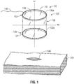
- FIG. 1 illustrates a surgical apparatus 10 in accordance with the principles of the present disclosure.
- the surgical apparatus 10 is adapted for insertion in a tissue opening 106 within a tissue tract 105 , e.g., through the abdominal or peritoneal lining in connection with a laparoscopic surgical procedure.
- the surgical apparatus 10 will be described in greater detail hereinbelow.
- the surgical apparatus 10 includes a flexible sleeve 100 defining a generally cylindrical shape.
- the sleeve 100 may define other configurations both prior and subsequent to insertion within the tissue tract 105 .
- the sleeve 100 defines a longitudinal axis " L ", a radial axis "R”, and includes a proximal end 110 and a distal end 120 with a sheath or liner 130 extending therebetween.
- the sheath 130 in one embodiment, exhibits a generally cylindrical configuration. It is envisioned that the sheath 130 may exhibit other configurations.
- the sheath 130 defines an inner surface 130a and an outer surface 130b.
- the inner surface 130a defines a longitudinal passage 131 therein having a diameter of "D1" in its radial dimension as illustrated in FIG. 1A . In one embodiment, the radial dimension, "D1", is uniform along the length of the sheath 130. It is envisioned that the entire length of the sheath 130 is insertable into the tissue opening 106.
- a ring member 111, 121 is mounted respectively at each end 110, 120 of the sleeve 100 in connection with the sheath 130.
- Each ring member includes an inner surface and an outer surface.
- the ring member 111 at the proximal end 110 includes an inner surface 111a and an outer surface 111b.
- the ring member 121 at the distal end 120 also includes an inner surface 121a and an outer surface 121b.
- the proximal ring member 111 is configured to be disposed exteriorly of the tissue opening 106, while the distal ring member 121 is configured to disposed interiorly with respect to the tissue opening 106.
- the inner surfaces 111a and 121a define an inner diameter "D1" identical to the diameter of the longitudinal passage 131.
- the outer surfaces 111b and 121b are configured to have an outer diameter "D2," which equals to or is greater than the radial dimension "D3" of the tissue opening 106. Due to their relatively large dimensions, the outer surfaces 111b and 112b inhibit the ring members 111 and 121 from travelling across the tissue opening 106 without user intervention.
- the ring member 121 needs to be titled or biased to reduce its radial dimension to an extent (e.g.
- the distal ring member 121 is disposed interiorly of the tissue opening 106 as illustrated in FIG. 3 , the distal ring member 121 returns to its normal, unbiased position.
- the radial dimension "D2" of the outer surface 121b of the distal ring member 121 facilitates anchoring the surgical apparatus 10 within the tissue tract 105.
- Each of the ring members (e.g. the proximal ring member 111) is configured to roll along the longitudinal length of the sheath 130 to approximate and retract the tissue tract 105, causing the height of the surgical apparatus 10 to approximate the thickness of the tissue tract 105, as illustrated in FIGS. 4 and 5 .
- the sheath 130 is wrapped about the ring member 111 and rolled upon itself, and transitions from an unrolled or first state as illustrated in FIG. 1A to a rolled or second state as illustrated in FIGS. 4 and 5 .
- FIGS. 4 and 5 illustrate the surgical apparatus 10 in a retracted position at which the ring members 111 and 121 abut the tissue tract 105 thereby anchoring the surgical apparatus 10 with respect to the tissue tract 106.
- the radial dimension of the longitudinal passage 131 is identical to that of the tissue opening 106 "D3.”
- the sheath 130 forms a sealing relation with the tissue opening 106.
- the surgical apparatus 10 defines a height from the distal end 120 to the proximal end 110. The height varies depending on the rolling state of the sheath 130. When the sheath 130 is unrolled, as illustrated in FIG. 1A , the surgical apparatus 10 has a maximum height of "H1." When the sheath 130 is rolled upon itself to an extent that the proximal end 110 meets the distal end 120, not shown, the surgical apparatus 10 has a minimum height. Therefore, as the ring member 111 rolls along the sheath 130 in a distal direction, the surgical apparatus 10 transitions from a maximum height to a minimum height. As illustrated in FIGS. 4 and 5 , when the sheath 130 is rolled halfway, the surgical apparatus 10 has a height of "H2" which is less than the maximum height but greater than the minimum height.
- the height of the surgical apparatus 10 can be adjusted to accommodate tissue tracts 105 of different thickness. In a situation when the maximum height of the surgical apparatus 10 readily fits in the tissue tract 105, the sheath 130 needs not be rolled upon. However, in situations in which the tissue tract 105 has a thickness, as illustrated in FIG. 5 , that is less than the maximum height of the surgical apparatus 10, the ring member 111 may roll distally along the length of the sheath 130 to approximate the tissue tract 105, causing the height of the surgical apparatus 10 to approximate the thickness of the tissue tract 105, as illustrated in FIG. 5 .
- a suture may be used to select, secure and maintain a desired height of the surgical apparatus 10.
- Other fastening means are also envisioned, including clips, snaps, or hooks for holding the surgical apparatus 10 at a desired height.
- the surgical apparatus 10 further includes a cord 140 connected to the proximal end 110 as illustrated in FIG. 1 .
- the cord 140 has a length sufficient to loop and tie circumferentially around the outer surface 130b of the surgical apparatus 10 to reduce the radial dimension of the longitudinal passage 131 of the surgical apparatus 10.
- the longitudinal passage 131 of the surgical apparatus 10 is adapted to receive a portal member 20 such as that disclosed in U.S. patent application Serial No. 12/244,024 , Pub. No. US 2009/0093752 A1, filed October 2, 2008 .
- the portal member 20 defines at least one longitudinal passage 230 between its proximal end 210 and its distal end 220 for reception of a surgical object therethrough.
- the portal member 20 defines an hourglass configuration.
- the portal member 20 defines a maximum radial dimension "D5" at its proximal end 210 and its distal end 220 which gradually becomes smaller towards the middle portion 240 where the minimum radial dimension "D6" is defined.
- the maximum radial dimension "D5" of the portal member 20 is less than the radial dimension "D3" of the longitudinal passage 131 when the surgical apparatus 10 is in its retracted position. Due to the small dimension of the portal member 20, if the portal member 20 were disposed in the surgical apparatus 10 in a freestanding position as illustrated in FIGS. 7 and 8 , gravity would induce the portal member 20 to fall through the longitudinal passage 131 and into the patient's body cavity.
- the cord 140 is configured to loop and tie around the outer surface 130b of the surgical apparatus 10 immediately above the tissue opening 106, which, in turn, reduces the radial dimension of the longitudinal passage 131 of the surgical apparatus 10 that is positioned immediately above the tissue opening 106.
- the longitudinal passage 131 at the upper side 106a of the tissue opening 106 is reduced to a radial dimension "D7" which is less than the maximum radial dimension "D5" of the portal member 20, thereby preventing the proximal end 210 of the portal member 20 from falling through.
- the longitudinal passage 131 at the upper side 106a of the tissue opening 106 forms a suspended relation with respect to the portal member 20, thereby securing the portal member 20 with respect to the surgical apparatus 10. Further, the longitudinal passage 131 at the upper side 106a of the tissue opening forms an air-tight or sealing relationship with the portal member 20.
- the longitudinal passage 131 at the lower side 106b of the tissue opening 106 remains to have the same dimension "D3" as that of the tissue opening 106, and the sheath 130 at the lower side 106b of the tissue opening 106 continues to form a sealing relationship with the lower side 106b of the tissue opening 106.
- the ring members 111 and 121 are made of a rigid or semi rigid material such as plastic or rubber.
- the sheath 130 is made of a flexible material that is also able to establish a sealing relation with the tissue tract 105 and is also able to form a sealing relation with surgical objects inserted within the longitudinal passage 131.
- the cord 140 is made of a flexible material, such as fiber or braid in the form of a thread or suture.
- the portal member 20 may be made from a semi-resilient, disposable, compressible and flexible type (e.g. rubber or sponge) material, for example, but not limited to, a suitable foam, gel material, or soft rubber having sufficient compliance to form a seal about one or more surgical objects, and also establish a sealing relation with the tissue tract 105 and with the surgical object.
- the foam includes a polyisoprene material. The resilient nature of the portal member 20 provides an easy insertion and removal of the portal member 20 through the surgical apparatus 10.
- the cord 140 is an integrated part of the proximal end 110.
- the cord 140 is permanently attached to the proximal end 110 of the surgical apparatus 10 by glue, suture or by an overmolding process.
- the cord 140 is detachably connected to the proximal end 110 of the surgical apparatus 10.
- the surgeon first unrolls the sheath 130 to its unrolled state by rolling the proximal ring member 111 in a proximal direction along the length of the sheath 130, as illustrated in FIGS. 1 and 1A .
- the surgeon tilts the distal end 120 of the surgical apparatus 10 as illustrated in FIG. 2 , and introduces the distal end 120 of the surgical apparatus 10 into the tissue tract 105 through the tissue opening 106.
- the distal portion 120 is anchored interiorly with respect to the tissue tract 105 as illustrated in FIGS.
- the surgeon retracts the tissue opening 106 by rolling the ring member 111 in a distal direction along length of the sheath 130 to create tension in the sheath 130.
- the same rolling step also causes the ring member 111 to approach the upper side of the tissue tract 105, which, in turn, reduces height of the surgical apparatus 10 to approximate the thickness of the tissue tract 105.
- the surgeon introduces a portal member 20 into the longitudinal passage 131 of the surgical apparatus 10 as illustrated in FIGS. 6-8 , and holds the proximal end 210 of the portal member 20 above the upper side of the tissue tract 105.
- the surgeon loops the cord 140 around the outer surface 130b of the sheath 130 to reduce the radial dimension of the longitudinal passage 131 of the surgical apparatus 10 at the upper side 106a of the tissue opening 106, so that the longitudinal passage 131 forms a sealing relation with respect to the portal member 20.
- the surgical apparatus 10 can sealingly engage instruments of various dimensions and maintain the insufflation pressure at the tissue opening 106. For instance, when a large instrument is desired to be operated through the tissue opening 106, it can be positioned directly within the longitudinal passage 131 and readily form a sealing relation with the surgical apparatus 10. When an instrument of a smaller dimension is desired to be operated through the tissue opening 106, the surgical apparatus 10 readily accommodates an intermediate access port (e.g. portal member 20) and forms a sealing relation therewith, and the intermediate access port is configured to sealingly receive instruments of small dimensions.
- an intermediate access port e.g. portal member 20
Landscapes
- Health & Medical Sciences (AREA)
- Surgery (AREA)
- Life Sciences & Earth Sciences (AREA)
- Biomedical Technology (AREA)
- Nuclear Medicine, Radiotherapy & Molecular Imaging (AREA)
- Engineering & Computer Science (AREA)
- Pathology (AREA)
- Heart & Thoracic Surgery (AREA)
- Medical Informatics (AREA)
- Molecular Biology (AREA)
- Animal Behavior & Ethology (AREA)
- General Health & Medical Sciences (AREA)
- Public Health (AREA)
- Veterinary Medicine (AREA)
- Surgical Instruments (AREA)
Claims (16)
- Appareil chirurgical à positionner à l'intérieur d'un tractus tissulaire ayant accès à une cavité corporelle sous-jacente comprenant :un manchon souple (100) définissant un axe longitudinal (L), une extrémité proximale (110), une extrémité distale (120) et un passage (131) pour la réception d'un objet, l'extrémité proximale à localiser à l'extérieur de la cavité corporelle, l'extrémité distale à insérer dans la cavité corporelle, les extrémités proximale et distale étant ouvertes pour fournir un accès à la cavité corporelle, etun cordon (140) ;caractérisé en ce qu'une extrémité du cordon est attachée à l'extrémité proximale du manchon souple (100), le reste du cordon étant libre, etl'appareil comprend en outre un dispositif d'accès (20) pouvant être inséré dans le manchon souple (100), de sorte que le cordon (140) est conçu pour être en boucle et serré autour de la surface extérieure dudit manchon souple, réduisant de ce fait le diamètre du manchon souple pour créer une relation d'étanchéité entre ledit dispositif d'accès et ledit manchon.
- Appareil chirurgical selon la revendication 1, dans lequel le cordon (140) est conçu pour serrer autour d'une surface extérieure (130b) du manchon souple (100).
- Appareil chirurgical selon la revendication 1, dans lequel le manchon souple (100) inclut une gaine (130) dans une configuration globalement cylindrique.
- Appareil chirurgical selon l'une quelconque des revendications précédentes, dans lequel l'appareil chirurgical définit une hauteur réglable.
- Appareil chirurgical selon l'une quelconque des revendications précédentes, dans lequel la formation en boucle et le serrage du cordon (140) autour de la surface extérieure du manchon souple (100) fait subir une transition au manchon souple d'un premier diamètre à un second diamètre.
- Appareil chirurgical selon la revendication 5, dans lequel le passage (131) définit le premier diamètre, le dispositif d'accès (20) définit le second diamètre, et le premier diamètre est plus grand que le second diamètre.
- Dispositif chirurgical selon la revendication 6, dans lequel le cordon est configuré pour sécuriser le dispositif d'accès (20) à l'intérieur du passage du manchon souple (100).
- Appareil chirurgical selon l'une quelconque des revendications précédentes, dans lequel le manchon souple (100) inclut un élément annulaire proximal (111) et un élément annulaire distal (121) attachés à chaque extrémité de ce dernier.
- Appareil chirurgical selon la revendication 8, dans lequel l'élément annulaire distal (121) est conçu pour être disposé à l'intérieur du tractus tissulaire.
- Appareil chirurgical selon la revendication 8 ou la revendication 9, dans lequel l'élément annulaire proximal (111) est conçu pour être disposé à l'extérieur du tractus tissulaire.
- Appareil chirurgical selon l'une quelconque des revendications 8 à 10, dans lequel
les éléments annulaires (111, 121) sont agencés le long de l'axe longitudinal (L) ;
le manchon souple (100) comprend une gaine (130) s'étendant entre les deux éléments annulaires (111, 121) le long de l'axe longitudinal (L) ; et
le cordon (140) a deux extrémités, une extrémité étant attachée à un élément annulaire particulier (111, 121), dans lequel le cordon a la longueur suffisante pour former une boucle et serrer la surface extérieure de la gaine faisant subir une transition à la gaine d'un premier diamètre à un second diamètre. - Appareil chirurgical selon la revendication 11, dans lequel la gaine (130) définit un passage (131) s'étendant entre les deux éléments annulaires (111, 121) et configurée pour recevoir un objet (20).
- Appareil chirurgical selon la revendication 11 ou la revendication 12, dans lequel la gaine (130) définit une configuration globalement cylindrique.
- Appareil chirurgical selon l'une quelconque des revendications précédentes, dans lequel le cordon (140) est configuré pour réduire le diamètre du passage (131) pour former une relation d'étanchéité avec le dispositif d'accès (20).
- Appareil chirurgical selon l'une quelconque des revendications précédentes, dans lequel le cordon entier est disposé à l'extérieur de la cavité corporelle.
- Appareil chirurgical selon l'une quelconque des revendications précédentes, dans lequel le cordon entier est disposé à l'extérieur du tractus tissulaire.
Applications Claiming Priority (2)
| Application Number | Priority Date | Filing Date | Title |
|---|---|---|---|
| US201161469220P | 2011-03-30 | 2011-03-30 | |
| US13/231,123 US20120253136A1 (en) | 2011-03-30 | 2011-09-13 | Access port and flexible sleeve with attached cord |
Publications (2)
| Publication Number | Publication Date |
|---|---|
| EP2505152A1 EP2505152A1 (fr) | 2012-10-03 |
| EP2505152B1 true EP2505152B1 (fr) | 2017-03-15 |
Family
ID=45952920
Family Applications (1)
| Application Number | Title | Priority Date | Filing Date |
|---|---|---|---|
| EP12162048.8A Not-in-force EP2505152B1 (fr) | 2011-03-30 | 2012-03-30 | Orifice d'accès et manchon flexible avec cordon fixé |
Country Status (5)
| Country | Link |
|---|---|
| US (1) | US20120253136A1 (fr) |
| EP (1) | EP2505152B1 (fr) |
| JP (1) | JP2012210402A (fr) |
| AU (1) | AU2012201013B2 (fr) |
| CA (1) | CA2769069A1 (fr) |
Families Citing this family (13)
| Publication number | Priority date | Publication date | Assignee | Title |
|---|---|---|---|---|
| US9421032B2 (en) * | 2010-06-16 | 2016-08-23 | Covidien Lp | Seal port with blood collector |
| US8668642B2 (en) * | 2010-11-23 | 2014-03-11 | Covidien Lp | Port device including retractable endoscope cleaner |
| US9549758B2 (en) * | 2011-03-23 | 2017-01-24 | Covidien Lp | Surgical access assembly with adapter |
| US9119666B2 (en) * | 2011-03-25 | 2015-09-01 | Covidien Lp | Access port with integrated flexible sleeve |
| US9028403B2 (en) * | 2012-01-19 | 2015-05-12 | Covidien Lp | Access port having rollable proximal end |
| US20130190573A1 (en) * | 2012-01-19 | 2013-07-25 | Covidien Lp | Wound protector including flexible and rigid liners |
| US9463007B2 (en) * | 2012-02-23 | 2016-10-11 | Covidien Lp | Adjustable height port including retention elements |
| US9017249B2 (en) | 2012-03-26 | 2015-04-28 | Covidien Lp | Surgical access assembly and method of use therefor |
| US9149178B2 (en) * | 2012-03-26 | 2015-10-06 | Covidien Lp | Surgical access assembly and method of use therefor |
| ES2806266T3 (es) | 2013-03-15 | 2021-02-17 | Applied Med Resources | Junta de sellado quirúrgica de trocar |
| AU2015249652B2 (en) * | 2014-04-23 | 2020-02-20 | Applied Medical Resources Corporation | Systems and methods for tissue removal |
| US10932767B2 (en) | 2018-12-07 | 2021-03-02 | Covidien Lp | Surgical access assembly and method of use therefor |
| ES2961466T3 (es) * | 2020-12-10 | 2024-03-12 | Ivoclar Vivadent Ag | Elemento tensor de película |
Family Cites Families (7)
| Publication number | Priority date | Publication date | Assignee | Title |
|---|---|---|---|---|
| DE4140156C2 (de) * | 1991-12-05 | 1995-07-06 | Guenter Dr Med Schaller | Hilfsmittel für laparoskopische Operationen |
| US5653705A (en) * | 1994-10-07 | 1997-08-05 | General Surgical Innovations, Inc. | Laparoscopic access port for surgical instruments or the hand |
| US6382211B1 (en) * | 1997-07-21 | 2002-05-07 | Medical Creative Technologies, Inc. | Surgical retractor liner appliance |
| US7537564B2 (en) * | 1998-12-01 | 2009-05-26 | Atropos Limited | Wound retractor device |
| AU773994B2 (en) * | 1998-12-01 | 2004-06-10 | Atropos Limited | A surgical device for retracting and/or sealing an incision |
| US20090093752A1 (en) | 2007-10-05 | 2009-04-09 | Tyco Healthcare Group Lp | Seal anchor for use in surgical procedures |
| US8257251B2 (en) * | 2009-04-08 | 2012-09-04 | Ethicon Endo-Surgery, Inc. | Methods and devices for providing access into a body cavity |
-
2011
- 2011-09-13 US US13/231,123 patent/US20120253136A1/en not_active Abandoned
-
2012
- 2012-02-21 CA CA2769069A patent/CA2769069A1/fr not_active Abandoned
- 2012-02-21 AU AU2012201013A patent/AU2012201013B2/en not_active Ceased
- 2012-03-09 JP JP2012052945A patent/JP2012210402A/ja active Pending
- 2012-03-30 EP EP12162048.8A patent/EP2505152B1/fr not_active Not-in-force
Non-Patent Citations (1)
| Title |
|---|
| None * |
Also Published As
| Publication number | Publication date |
|---|---|
| AU2012201013B2 (en) | 2014-07-24 |
| CA2769069A1 (fr) | 2012-09-30 |
| EP2505152A1 (fr) | 2012-10-03 |
| US20120253136A1 (en) | 2012-10-04 |
| JP2012210402A (ja) | 2012-11-01 |
| AU2012201013A1 (en) | 2012-10-18 |
Similar Documents
| Publication | Publication Date | Title |
|---|---|---|
| EP2505152B1 (fr) | Orifice d'accès et manchon flexible avec cordon fixé | |
| EP2502589B1 (fr) | Orifice d'accès équipé d'une gaine enroulable intégrée | |
| EP2630929B1 (fr) | Dispositif protecteur de blessure multi-portions | |
| JP5830318B2 (ja) | 調整可能な高さを有するシールポート | |
| EP2277464B1 (fr) | Port chirurgical et ensemble introducteur sécable | |
| US9028403B2 (en) | Access port having rollable proximal end | |
| US9463007B2 (en) | Adjustable height port including retention elements | |
| US20140163324A1 (en) | Seal anchor introducer including biasing member | |
| JP2011104378A (ja) | ポート固定デバイス | |
| EP2324783A1 (fr) | Introducteur d'ancrage de joint doté d'un élément de biais | |
| WO2011072100A2 (fr) | Procédés et dispositifs destinés à procurer un accès dans une cavité corporelle | |
| CA2720417A1 (fr) | Introducteur de dispositif d'ancrage a obturation et element de sollicitation |
Legal Events
| Date | Code | Title | Description |
|---|---|---|---|
| PUAI | Public reference made under article 153(3) epc to a published international application that has entered the european phase |
Free format text: ORIGINAL CODE: 0009012 |
|
| AK | Designated contracting states |
Kind code of ref document: A1 Designated state(s): AL AT BE BG CH CY CZ DE DK EE ES FI FR GB GR HR HU IE IS IT LI LT LU LV MC MK MT NL NO PL PT RO RS SE SI SK SM TR |
|
| AX | Request for extension of the european patent |
Extension state: BA ME |
|
| RAP1 | Party data changed (applicant data changed or rights of an application transferred) |
Owner name: COVIDIEN LP |
|
| 17P | Request for examination filed |
Effective date: 20130107 |
|
| GRAP | Despatch of communication of intention to grant a patent |
Free format text: ORIGINAL CODE: EPIDOSNIGR1 |
|
| GRAJ | Information related to disapproval of communication of intention to grant by the applicant or resumption of examination proceedings by the epo deleted |
Free format text: ORIGINAL CODE: EPIDOSDIGR1 |
|
| GRAP | Despatch of communication of intention to grant a patent |
Free format text: ORIGINAL CODE: EPIDOSNIGR1 |
|
| RIN1 | Information on inventor provided before grant (corrected) |
Inventor name: RODRIGUES, ANIBAL JR. |
|
| INTG | Intention to grant announced |
Effective date: 20160926 |
|
| INTG | Intention to grant announced |
Effective date: 20161005 |
|
| GRAS | Grant fee paid |
Free format text: ORIGINAL CODE: EPIDOSNIGR3 |
|
| GRAA | (expected) grant |
Free format text: ORIGINAL CODE: 0009210 |
|
| AK | Designated contracting states |
Kind code of ref document: B1 Designated state(s): AL AT BE BG CH CY CZ DE DK EE ES FI FR GB GR HR HU IE IS IT LI LT LU LV MC MK MT NL NO PL PT RO RS SE SI SK SM TR |
|
| REG | Reference to a national code |
Ref country code: CH Ref legal event code: EP Ref country code: GB Ref legal event code: FG4D |
|
| REG | Reference to a national code |
Ref country code: FR Ref legal event code: PLFP Year of fee payment: 6 |
|
| REG | Reference to a national code |
Ref country code: IE Ref legal event code: FG4D |
|
| REG | Reference to a national code |
Ref country code: AT Ref legal event code: REF Ref document number: 874764 Country of ref document: AT Kind code of ref document: T Effective date: 20170415 |
|
| REG | Reference to a national code |
Ref country code: DE Ref legal event code: R096 Ref document number: 602012029755 Country of ref document: DE |
|
| PGFP | Annual fee paid to national office [announced via postgrant information from national office to epo] |
Ref country code: FR Payment date: 20170322 Year of fee payment: 6 |
|
| PGFP | Annual fee paid to national office [announced via postgrant information from national office to epo] |
Ref country code: GB Payment date: 20170324 Year of fee payment: 6 Ref country code: IE Payment date: 20170323 Year of fee payment: 6 |
|
| REG | Reference to a national code |
Ref country code: NL Ref legal event code: MP Effective date: 20170315 |
|
| REG | Reference to a national code |
Ref country code: LT Ref legal event code: MG4D |
|
| PG25 | Lapsed in a contracting state [announced via postgrant information from national office to epo] |
Ref country code: GR Free format text: LAPSE BECAUSE OF FAILURE TO SUBMIT A TRANSLATION OF THE DESCRIPTION OR TO PAY THE FEE WITHIN THE PRESCRIBED TIME-LIMIT Effective date: 20170616 Ref country code: HR Free format text: LAPSE BECAUSE OF FAILURE TO SUBMIT A TRANSLATION OF THE DESCRIPTION OR TO PAY THE FEE WITHIN THE PRESCRIBED TIME-LIMIT Effective date: 20170315 Ref country code: NO Free format text: LAPSE BECAUSE OF FAILURE TO SUBMIT A TRANSLATION OF THE DESCRIPTION OR TO PAY THE FEE WITHIN THE PRESCRIBED TIME-LIMIT Effective date: 20170615 Ref country code: FI Free format text: LAPSE BECAUSE OF FAILURE TO SUBMIT A TRANSLATION OF THE DESCRIPTION OR TO PAY THE FEE WITHIN THE PRESCRIBED TIME-LIMIT Effective date: 20170315 Ref country code: LT Free format text: LAPSE BECAUSE OF FAILURE TO SUBMIT A TRANSLATION OF THE DESCRIPTION OR TO PAY THE FEE WITHIN THE PRESCRIBED TIME-LIMIT Effective date: 20170315 |
|
| PGFP | Annual fee paid to national office [announced via postgrant information from national office to epo] |
Ref country code: DE Payment date: 20170331 Year of fee payment: 6 |
|
| REG | Reference to a national code |
Ref country code: AT Ref legal event code: MK05 Ref document number: 874764 Country of ref document: AT Kind code of ref document: T Effective date: 20170315 |
|
| PG25 | Lapsed in a contracting state [announced via postgrant information from national office to epo] |
Ref country code: SE Free format text: LAPSE BECAUSE OF FAILURE TO SUBMIT A TRANSLATION OF THE DESCRIPTION OR TO PAY THE FEE WITHIN THE PRESCRIBED TIME-LIMIT Effective date: 20170315 Ref country code: RS Free format text: LAPSE BECAUSE OF FAILURE TO SUBMIT A TRANSLATION OF THE DESCRIPTION OR TO PAY THE FEE WITHIN THE PRESCRIBED TIME-LIMIT Effective date: 20170315 Ref country code: BG Free format text: LAPSE BECAUSE OF FAILURE TO SUBMIT A TRANSLATION OF THE DESCRIPTION OR TO PAY THE FEE WITHIN THE PRESCRIBED TIME-LIMIT Effective date: 20170615 Ref country code: LV Free format text: LAPSE BECAUSE OF FAILURE TO SUBMIT A TRANSLATION OF THE DESCRIPTION OR TO PAY THE FEE WITHIN THE PRESCRIBED TIME-LIMIT Effective date: 20170315 |
|
| PG25 | Lapsed in a contracting state [announced via postgrant information from national office to epo] |
Ref country code: NL Free format text: LAPSE BECAUSE OF FAILURE TO SUBMIT A TRANSLATION OF THE DESCRIPTION OR TO PAY THE FEE WITHIN THE PRESCRIBED TIME-LIMIT Effective date: 20170315 |
|
| PG25 | Lapsed in a contracting state [announced via postgrant information from national office to epo] |
Ref country code: SK Free format text: LAPSE BECAUSE OF FAILURE TO SUBMIT A TRANSLATION OF THE DESCRIPTION OR TO PAY THE FEE WITHIN THE PRESCRIBED TIME-LIMIT Effective date: 20170315 Ref country code: ES Free format text: LAPSE BECAUSE OF FAILURE TO SUBMIT A TRANSLATION OF THE DESCRIPTION OR TO PAY THE FEE WITHIN THE PRESCRIBED TIME-LIMIT Effective date: 20170315 Ref country code: EE Free format text: LAPSE BECAUSE OF FAILURE TO SUBMIT A TRANSLATION OF THE DESCRIPTION OR TO PAY THE FEE WITHIN THE PRESCRIBED TIME-LIMIT Effective date: 20170315 Ref country code: IT Free format text: LAPSE BECAUSE OF FAILURE TO SUBMIT A TRANSLATION OF THE DESCRIPTION OR TO PAY THE FEE WITHIN THE PRESCRIBED TIME-LIMIT Effective date: 20170315 Ref country code: AT Free format text: LAPSE BECAUSE OF FAILURE TO SUBMIT A TRANSLATION OF THE DESCRIPTION OR TO PAY THE FEE WITHIN THE PRESCRIBED TIME-LIMIT Effective date: 20170315 Ref country code: RO Free format text: LAPSE BECAUSE OF FAILURE TO SUBMIT A TRANSLATION OF THE DESCRIPTION OR TO PAY THE FEE WITHIN THE PRESCRIBED TIME-LIMIT Effective date: 20170315 Ref country code: CZ Free format text: LAPSE BECAUSE OF FAILURE TO SUBMIT A TRANSLATION OF THE DESCRIPTION OR TO PAY THE FEE WITHIN THE PRESCRIBED TIME-LIMIT Effective date: 20170315 |
|
| REG | Reference to a national code |
Ref country code: CH Ref legal event code: PL |
|
| PG25 | Lapsed in a contracting state [announced via postgrant information from national office to epo] |
Ref country code: SM Free format text: LAPSE BECAUSE OF FAILURE TO SUBMIT A TRANSLATION OF THE DESCRIPTION OR TO PAY THE FEE WITHIN THE PRESCRIBED TIME-LIMIT Effective date: 20170315 Ref country code: PT Free format text: LAPSE BECAUSE OF FAILURE TO SUBMIT A TRANSLATION OF THE DESCRIPTION OR TO PAY THE FEE WITHIN THE PRESCRIBED TIME-LIMIT Effective date: 20170717 Ref country code: PL Free format text: LAPSE BECAUSE OF FAILURE TO SUBMIT A TRANSLATION OF THE DESCRIPTION OR TO PAY THE FEE WITHIN THE PRESCRIBED TIME-LIMIT Effective date: 20170315 Ref country code: IS Free format text: LAPSE BECAUSE OF FAILURE TO SUBMIT A TRANSLATION OF THE DESCRIPTION OR TO PAY THE FEE WITHIN THE PRESCRIBED TIME-LIMIT Effective date: 20170715 |
|
| REG | Reference to a national code |
Ref country code: DE Ref legal event code: R097 Ref document number: 602012029755 Country of ref document: DE |
|
| PLBE | No opposition filed within time limit |
Free format text: ORIGINAL CODE: 0009261 |
|
| STAA | Information on the status of an ep patent application or granted ep patent |
Free format text: STATUS: NO OPPOSITION FILED WITHIN TIME LIMIT |
|
| PG25 | Lapsed in a contracting state [announced via postgrant information from national office to epo] |
Ref country code: DK Free format text: LAPSE BECAUSE OF FAILURE TO SUBMIT A TRANSLATION OF THE DESCRIPTION OR TO PAY THE FEE WITHIN THE PRESCRIBED TIME-LIMIT Effective date: 20170315 Ref country code: LU Free format text: LAPSE BECAUSE OF NON-PAYMENT OF DUE FEES Effective date: 20170330 Ref country code: MC Free format text: LAPSE BECAUSE OF FAILURE TO SUBMIT A TRANSLATION OF THE DESCRIPTION OR TO PAY THE FEE WITHIN THE PRESCRIBED TIME-LIMIT Effective date: 20170315 |
|
| 26N | No opposition filed |
Effective date: 20171218 |
|
| PG25 | Lapsed in a contracting state [announced via postgrant information from national office to epo] |
Ref country code: LI Free format text: LAPSE BECAUSE OF NON-PAYMENT OF DUE FEES Effective date: 20170331 Ref country code: CH Free format text: LAPSE BECAUSE OF NON-PAYMENT OF DUE FEES Effective date: 20170331 Ref country code: SI Free format text: LAPSE BECAUSE OF FAILURE TO SUBMIT A TRANSLATION OF THE DESCRIPTION OR TO PAY THE FEE WITHIN THE PRESCRIBED TIME-LIMIT Effective date: 20170315 |
|
| REG | Reference to a national code |
Ref country code: BE Ref legal event code: MM Effective date: 20170331 |
|
| PG25 | Lapsed in a contracting state [announced via postgrant information from national office to epo] |
Ref country code: BE Free format text: LAPSE BECAUSE OF NON-PAYMENT OF DUE FEES Effective date: 20170331 |
|
| PG25 | Lapsed in a contracting state [announced via postgrant information from national office to epo] |
Ref country code: MT Free format text: LAPSE BECAUSE OF NON-PAYMENT OF DUE FEES Effective date: 20170330 |
|
| REG | Reference to a national code |
Ref country code: DE Ref legal event code: R119 Ref document number: 602012029755 Country of ref document: DE |
|
| GBPC | Gb: european patent ceased through non-payment of renewal fee |
Effective date: 20180330 |
|
| REG | Reference to a national code |
Ref country code: IE Ref legal event code: MM4A |
|
| PG25 | Lapsed in a contracting state [announced via postgrant information from national office to epo] |
Ref country code: DE Free format text: LAPSE BECAUSE OF NON-PAYMENT OF DUE FEES Effective date: 20181002 Ref country code: IE Free format text: LAPSE BECAUSE OF NON-PAYMENT OF DUE FEES Effective date: 20180330 |
|
| PG25 | Lapsed in a contracting state [announced via postgrant information from national office to epo] |
Ref country code: GB Free format text: LAPSE BECAUSE OF NON-PAYMENT OF DUE FEES Effective date: 20180330 |
|
| PG25 | Lapsed in a contracting state [announced via postgrant information from national office to epo] |
Ref country code: FR Free format text: LAPSE BECAUSE OF NON-PAYMENT OF DUE FEES Effective date: 20180331 |
|
| PG25 | Lapsed in a contracting state [announced via postgrant information from national office to epo] |
Ref country code: HU Free format text: LAPSE BECAUSE OF FAILURE TO SUBMIT A TRANSLATION OF THE DESCRIPTION OR TO PAY THE FEE WITHIN THE PRESCRIBED TIME-LIMIT; INVALID AB INITIO Effective date: 20120330 |
|
| PG25 | Lapsed in a contracting state [announced via postgrant information from national office to epo] |
Ref country code: CY Free format text: LAPSE BECAUSE OF NON-PAYMENT OF DUE FEES Effective date: 20170315 |
|
| PG25 | Lapsed in a contracting state [announced via postgrant information from national office to epo] |
Ref country code: MK Free format text: LAPSE BECAUSE OF FAILURE TO SUBMIT A TRANSLATION OF THE DESCRIPTION OR TO PAY THE FEE WITHIN THE PRESCRIBED TIME-LIMIT Effective date: 20170315 |
|
| PG25 | Lapsed in a contracting state [announced via postgrant information from national office to epo] |
Ref country code: TR Free format text: LAPSE BECAUSE OF FAILURE TO SUBMIT A TRANSLATION OF THE DESCRIPTION OR TO PAY THE FEE WITHIN THE PRESCRIBED TIME-LIMIT Effective date: 20170315 |
|
| PG25 | Lapsed in a contracting state [announced via postgrant information from national office to epo] |
Ref country code: AL Free format text: LAPSE BECAUSE OF FAILURE TO SUBMIT A TRANSLATION OF THE DESCRIPTION OR TO PAY THE FEE WITHIN THE PRESCRIBED TIME-LIMIT Effective date: 20170315 |