EP2505547B1 - Carter avec écran pour une buse de distribution de carburant - Google Patents
Carter avec écran pour une buse de distribution de carburant Download PDFInfo
- Publication number
- EP2505547B1 EP2505547B1 EP11160514.3A EP11160514A EP2505547B1 EP 2505547 B1 EP2505547 B1 EP 2505547B1 EP 11160514 A EP11160514 A EP 11160514A EP 2505547 B1 EP2505547 B1 EP 2505547B1
- Authority
- EP
- European Patent Office
- Prior art keywords
- display
- sleeve
- nozzle
- power
- display system
- Prior art date
- Legal status (The legal status is an assumption and is not a legal conclusion. Google has not performed a legal analysis and makes no representation as to the accuracy of the status listed.)
- Active
Links
Images


Classifications
-
- B—PERFORMING OPERATIONS; TRANSPORTING
- B67—OPENING, CLOSING OR CLEANING BOTTLES, JARS OR SIMILAR CONTAINERS; LIQUID HANDLING
- B67D—DISPENSING, DELIVERING OR TRANSFERRING LIQUIDS, NOT OTHERWISE PROVIDED FOR
- B67D7/00—Apparatus or devices for transferring liquids from bulk storage containers or reservoirs into vehicles or into portable containers, e.g. for retail sale purposes
- B67D7/06—Details or accessories
- B67D7/42—Filling nozzles
- B67D7/426—Filling nozzles including means for displaying information, e.g. for advertising
-
- B—PERFORMING OPERATIONS; TRANSPORTING
- B67—OPENING, CLOSING OR CLEANING BOTTLES, JARS OR SIMILAR CONTAINERS; LIQUID HANDLING
- B67D—DISPENSING, DELIVERING OR TRANSFERRING LIQUIDS, NOT OTHERWISE PROVIDED FOR
- B67D7/00—Apparatus or devices for transferring liquids from bulk storage containers or reservoirs into vehicles or into portable containers, e.g. for retail sale purposes
- B67D7/06—Details or accessories
- B67D7/42—Filling nozzles
- B67D7/425—Filling nozzles including components powered by electricity or light
Definitions
- the invention relates to a display system configured for fixing to a fuel dispensing nozzle, the display system comprising an electronic display screen, a display controller connected to the electronic display screen, and a power source for providing electric power to the electronic display screen and to the display controller.
- hand held fuel dispensing nozzles are used to dispense fuel, most likely, in a tank of a motorized vehicle.
- the dispensing nozzle containing a spout which can be inserted into the opening of the tank in the vehicle, is connected through a hose with the fuel pumping system and the storage tank of the gasoline dispensing facility.
- the nozzle itself is used to control the fluid flow after the spout is positioned into the opening of the tank in the vehicle.
- the nozzle has an integrated valve which can be mechanically opened and closed on the costumers demand by using a trigger of the nozzle.
- a known nozzle for a fuel dispensing system is disclosed in international patent application WO 99/44936 with title "Nozzle for a fuel dispensing system.”
- the known nozzle comprises a display coupled to a control system to display information to a customer.
- the display may display anything from transactional information to advertising and other information.
- the nozzle also comprises a keypad to allow a customer to input information to the control system.
- the known nozzle has a communication system capable of wireless, remote communication with an associated fuel dispensing system. Information may be transmitted from the dispenser to the nozzle to facilitate nozzle control or display to a customer, and information received at the nozzle may be transmitted to the dispenser for further processing or display.
- the embedding material is a synthetic material.
- the electronic components needed for driving an electronic display screen i.e., a controller and a power source are embedded in the embedding material.
- the controller and particularly the power source are shielded from the outside of the sleeve and the controller and particularly the power source are at the same time shielded from the inside the sleeve, e.g. from the channel.
- nozzles are no longer allowed to be fitted with a pin for keeping the trigger engaged while the spout of the nozzle is inserted in a car's tank inlet.
- nozzles are now manually operated, typically by a costumer.
- the costumer's visual attention is necessarily focused directly on the fuel nozzle itself, making the top of the fuel nozzle a desirable site for advertising.
- the sleeve has an internal channel for receiving the fuel dispensing nozzle. Accordingly there is no need to modify the fuel dispensing nozzle in any way. This is very advantageous since fuel dispensing nozzles are certified. A modified nozzle would have to be certified again were it to be retrofitted with a sleeve. In fact, since at least a portion of the sleeve comprises an elastic material exercising a contracting force around the channel for pressing the sleeve against the nozzle so as to fixate the display with respect to the nozzle when the nozzle is fitted into the channel, there is no need to use any other type of fixing means. Fixing means such as screws, clamps and the like would impose a safety risk. Fixing means such as glue would impair servicing and repair of the display system.
- the display system is very suitable for retrofitting an existing nozzle with a display screen.
- Potential sources of ignition include electric sparks, electrostatic discharges, high-power electronics and hot surfaces. Since at least the display controller and the power source are embedded a potential spark emanating from them is retained inside the sleeve. Even if the potential for sparks is not reduced by the choice of sleeve-material in which the controller and power source are embedded, the risk of a spark is significantly reduced by retaining it in the sleeve.
- the embedding material may be thermally conductive to improve heat conductance away from the electronics.
- the display controller and the power source are embedded, that is fixed firmly in the surrounding mass of embedding material which is a close and snug fit. As a result of the embedding the display controller and the power source are an integral part of the sleeve.
- the screen is integrated with the sleeve so as to form a one-part display system in which the screen is integrated.
- the screen is at least partially embedded in the embedding material.
- the sides of the electronic display screen may be embedded in the embedding material.
- a back side of the screen may also be embedded in the embedding material.
- the front-side may or may not be embedded in the embedding material.
- Embedding the front-side in the embedding material has the advantage that the protection of the sleeve extends to the front-side of the screen.
- Not embedding the front-side in the embedding material has the advantage that the display quality of the display system is improved.
- the front side of a LED display, especially of an organic LED display screen is not considered a high safety risk.
- the display controller and the power source are completely embedded; however, they may be enveloped by the embedding material from all sides except from one which is shielded by the electronic display screen.
- the power source e.g., a rechargeable battery is completely embedded, i.e., embedded from all sides.
- a spark emanating from the power source or controller is either stopped by the surrounding embedding material or by the display screen.
- the power source may comprise a rechargeable battery having recharging means for charging the battery from a wireless energy source.
- the recharging means would, e.g. be converting energy from a wireless source to energy stored in the battery.
- the power source may comprise a rechargeable battery which is charged from an inductive source.
- the inductive source may be close to a cradle of the fuel dispensing station to which the nozzle is attached through a hose.
- a power supply comprising a non-rechargeable battery integrated in the sleeve is not feasible since electronic displays require relatively much power. Batteries with a high capacity, needed for a long standing operation impose a safety risk in a volatile environment. Furthermore the space for batteries in the sleeve is limited. Exchangeable batteries with smaller size and lower capacity are less suitable because they have to be protected which makes it complex en expensive to exchange.
- the elastic material circumferentially surrounds a part of the channel. In this way the sleeve may be attached to the nozzle by an elastic force.
- the embedding material is a flexible or/and stretchable material.
- a flexible material the electronic components that are embedded in the flexible material are protected while the sleeve is fixed around the fuel nozzle.
- An advantage of a flexible sleeve is that it may be pulled over the nozzle together with its integrated electronics.
- the sleeve retains its flexibility when it is pulled over the nozzle.
- PolyUrethane An example of a suitable flexible material is PolyUrethane.
- the PolyUrethane may be colored into a desired color.
- Other choices for the flexible material are possible.
- the sleeve is a scuff guard.
- the scuff guard protects the connection between the nozzle and the hose to which the nozzle is attached.
- the connection is for example, a screwed connection.
- the embedding material and the elastic material are the same material.
- the portion of the sleeve which exerts a contracting force with an elastic material and the portion which embeds in a embedding material are formed as one-piece.
- the sleeve entirely consists of the same material.
- the material produces three advantageous effects with a single production step, first the non-conductive property of the material isolates the electronic parts from the surroundings by embedding them, second the elastic property acts as a means to fixate the sleeve to the nozzle, third the sleeve acts as a scuff guard, for protecting the connection between nozzle and hose.
- the elastic material may also circumferentially surrounds a part of the channel
- the sleeve is sufficiently flexible so that different shaped nozzles fit into the channel. This has the advantage that one sleeve design may be used for multiple nozzles of different designs.
- the electronic screen is an organic LED display screen.
- organic LED display screen require less power compared to LCD screens. Furthermore organic LED display screen have a broader operating temperature so that no additional heating or cooling features are required. For example, an OLED display screen may be used that can operate when external temperature ranges form -40°C to +70°C, without the need for heaters or coolers.
- the low power light emitting diode display such as but not limited to an active matrix organic light emitting diode (AMOLED) display, comprises a substrate whereon a pixels of light emitting materials are sandwiched between thin electrodes. Since the light emitting material itself illuminates when power is applied to the corresponding electrodes, these kinds of displays do not require a backlight. Furthermore, an area on the display that should be black need not be illuminated and does not require energy. In comparison a regular LCD with backlight wastes power because the liquid crystal acts as a polarizer which filters half of the light emitted by the backlight. Therefore an organic LED requires less power in comparison with regular liquid crystal displays with backlight. In addition thereto organic LED display screen have a broader operating temperature so that no additional heating or cooling features are required. Therefore the low power light emitting diode display forms an integral part of the sleeve that can be completely encapsulated by a synthetic material.
- the synthetic material could be PolyUrethanel.
- the display such as the light emitting diode display, may be connected with a printed circuit board (PCB) to address the display.
- PCB printed circuit board
- Driver electronics including features for power supply, could be assembled on or attached to the PCB.
- the display and additional electronics are preferably forming a one-part electronic assembly that could be completely encapsulated with a synthetic material.
- the electronic display screen is a flexible electronic display screen.
- a flexible electronic display screen for example, a flexible organic LED display
- the sleeve and all its integrated (embedded) electronics can be made flexible.
- the display controller may be mounted on a flexible PCB. The sleeve may be pulled over the nozzle together with its flexible integrated electronics, e.g., its flexible electronic display screen and/or flexible PCB.
- a flexible display for example a display wherein the functional layers for the display are deposited on a transparent and flexible plastic foil such as polyethylenenaphthalate or polyethyleneterephthalate this problem is avoided.
- the functional layers can be applied on a non transparent substrate as well and covered with a transparent layer.
- the functional layers for the display are deposited on a flexible substrate such as a copper or steel foil.
- the flexible display also offers more design freedom compared to a display containing a glass substrate.
- the sleeve may be partially formed into three dimensional figures, e.g., for advertising purposes.
- a flexible display is fitted more easily than a flat and rigid display.
- the area where the display is placed may be half-cylindrical.
- a flexible display further increases the vandalism resistance of the display system.
- the sleeve is harder to pull back from the nozzle, since the rigid surface of the display is no longer available as a suitable target on which a force can be applied.
- Having a flexible display, preferably together with a sleeve made out of a flexible material is particularly resistant to vandalism.
- the display screen comprises a flexible display screen bended, such that a first portion of the display screen makes an angle with a second portion of the display screen.
- the nozzle will be inserted along a bended path into a tank inlet.
- the angle under which the screen is best visible may vary between different car brands.
- the substrate on which the functional layers for the display are deposited is also used as an electronic circuit board comprising the display controller. In doing so all the electronic functions are build on one substrate by which a connection between the display and electronic assembly is eliminated. Reducing connections increases safety.
- the embedding of the display controller and the power source is obtained by molding over.
- the sleeve is used to form the scuff guard for the hand held fuel dispensing nozzle.
- the display and driver electronics are inserted into a mold and completely over-molded with a plastic forming process, such as but not limited to reactive injection molding (RIM).
- RIM reactive injection molding
- the display and additional electronics are completely encapsulated by the synthetic material of the scuff guard, resulting in a closed integer product without electrical contact for connection and without components that require much energy and or without components that could cause sparks or high temperatures.
- the display screen, power source and display controller form one part. This eases inserting of the electronics into a mold.
- the display system further comprises a wireless receiver for receiving digital data for display on the electronic screen, the embedding material of the sleeve also completely embedding the receiver.
- the wireless receiver may be used for receiving any one of firmware updates, digital data for processing and/or display on the display screen, in particular digital video data, and/or image data.
- the wireless receiver is a wireless transceiver, i.e., a wireless transmitter and a wireless receiver combined together in a single unit.
- a user of the display system may use the display system to enter commands.
- the display screen may be a touch screen.
- the command may be forwarded to a server for appropriate processing.
- the user could place an order, e.g. for a meal, via the display system.
- Sending or receiving information between the display system and a server may be routed via a dispensing facility, e.g., a dispensing facility to which the display system is attached via the nozzle and a hose.
- a dispensing facility e.g., a dispensing facility to which the display system is attached via the nozzle and a hose.
- the sleeve completely covers at least all components of the sleeve except the outer part of the electronic display screen.
- all parts, in particular all electronic parts of the display system are embedded in the sleeve, so as to form, a one-piece integrated display system.
- the sleeve completely covers at least all components of the sleeve including the outer part of the electronic display screen.
- a material transparent to visible light is used to cover the display.
- the entire sleeve is made of the same transparent material.
- the sleeve is made of the same transparent, flexible, elastic, material. The material may be slightly conductive for preventing electronic discharges.
- the power source comprises a power receiver for wirelessly receiving power. If power is transferred to the power source without a wire the power transfer will not be a likely source for ignition.
- a further aspect of the invention concerns fuel dispensing nozzle comprising a display system according to the invention.
- the fuel dispensing nozzle is attached to a hose.
- the hose comprises a wire for transferring power to a power transmitter for wirelessly transmitting power.
- the power transmitter is arranged with respect to the power receiver so that power may be transmitted during operational use of the display system.
- Power transmitter may be part of the hose or of the nozzle.
- the power transmitter is located at the end of the hose near the display system.
- there is no need to have a rechargeable element in the power source since it can be permanently powered.
- the display system may be created as a single one-part wireless piece, thus implying the safety advantages.
- wires could be used to supply the display system with energy from the external source.
- the wires could run from the external source, e.g., in the dispensing facility, down the fuel dispensing hose, to the nozzle.
- a complication is that the nozzle is often twisted and turned by the user relative to the fuel dispensing hose by which cables are also twisted and turned as which could cause damage to wires.
- a further aspect of the invention concerns a method for fixing a display system to a fuel dispensing nozzle.
- the display system comprising an electronic display screen, a display controller connected to the electronic display screen, a power source for providing electric power to the electronic display screen and to the display controller, and a sleeve having an internal channel for receiving the fuel dispensing nozzle, the comprising a embedding material embedding at least the display controller and the power source for shielding the display controller and the power source from the outside of the sleeve as a potential source of ignition.
- the method comprises fitting the nozzle into the channel thus exercising a contracting force around the channel for pressing the sleeve against the nozzle by a portion of the sleeve comprising an elastic material, accordingly fixing the display with respect to the nozzle.
- This method of fixing a display system has several advantages. It allows attaching the display system without any risk of electronics being exposed to a volatile environment and without using any further fixating means, such as screws. Further fixating means are likely not safe, and in any case require further scrutiny in light of safety. Furthermore, the nozzle does not need to be adapted in any way, thus avoiding recertification of the nozzle. Finally, this method allows retrofitting an existing nozzle with the new functionality provided by the display system.
- the invention provides the possibility to use an electronic display which satisfies safety regulations and which may be used in a volatile environment.
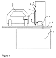
- FIG. 1 graphically represents a fuelling system in a typical retail gasoline dispensing facility.
- the fuelling system contains a pumping apparatus 1 that is on one side connected with a gasoline storage tank 2 that normally is positioned under the ground floor 3.
- the pumping system 1 is connected with a fuel dispensing nozzle 4 by a hose 5.
- the pumping apparatus 1 starts operating after the customer takes the fuel dispensing nozzle 4 from its base position 6.
- the customer will position the spout 7 attached to the end of fuel dispensing nozzle 4 into the opening of a tank 8.
- tank 8 will be the tank of a vehicle 9.
- Vehicle 9 is typically a car or a motorcycle.
- FIG. 2 shows nozzle 4 in more detail.
- a display system is attached to nozzle 4 .
- the display system has a sleeve, here in the form of a scuff guard 12.
- Scuff guard 12 comprises an electronic display screen 13.
- Display screen 13 is positioned such that it can be viewed by a user, while the user uses nozzle 4 to refuel his vehicle 9.
- the display may comprise a substrate 10 upon which pixels of light emitting materials 14 are applied.
- the nozzle is nozzle is fitted into a channel of the scuff guard 12. The spout went completely through the sleeve.
- the electronics of the display system such as a display controller and a power source are integrated into the scuff guard 12, this is not visible in Figure 2 , but can be seen in Figures 5b and 6 .
- the electronics of the display system are shielded by scuff guard 12 from the surrounding area, and in particular from the spout of the nozzle.
- the sleeve also acts as a scuff guard, but this is not necessary.
- the sleeve may be positioned over an existing scuff guard.
- the fuel delivery can be controlled by the costumer using the trigger 11, shown in figure 2 .
- This trigger is mechanically connected with a valve that is integrated in the fuel dispensing nozzle 4.
- This mechanical configuration of the valve and additive components for its operation in itself are known for someone skilled in the art and therefore not shown in the graphical representations.
- Trigger 11 and the integrated mechanical valve control system are part of the nozzle and not part of the display system.
- the sleeve wherein the display and associated electronics are integrated may be pulled over an existing nozzle.
- Figure 3 shows an electronic assembly 100, before embedding in scuff guard 12.
- the electronics form one part together with display screen 13.
- display 13 comprises pixels of light emitting materials such as in, but not limited to, an active matrix organic light emitting diode display (AMOLED).
- AMOLED active matrix organic light emitting diode display
- These kinds of displays typically comprise of a substrate 10 whereon pixels of light emitting materials 14 are applied.
- the light emitting materials illuminate light when power is supplied to the electrodes. Therefore these kinds of displays do not need a backlight which makes them more efficient and suitable for low power applications.
- the operation voltage of an organic LED is between 2 and 10 volts, which makes it possible to operate the display on intrinsic safety concerning the directive for electronics in high volatile environments.
- an organic LED has the advantage that the viewing angle can be up to 160 degree. Thus a bended display will still show clear images.
- FIG. 3 shows an exemplary embodiment of an electronic assembly 100.
- Electronic assembly 100 comprises a display screen 13, a display controller 16 connected to the electronic display screen, and a power source 18 for providing electric power to the electronic display screen and to the display controller.
- display 13 is connected through a flexible printed circuit 15 with the electronic display controller 16 for driving the display.
- the electronic display controller 16 for driving the display.
- a printed circuit 15 other connections are possible.
- extra electronic components 17 for other electronic functions, like wireless communication or car recognition systems may be assembled onto the flexible printed circuit 15.
- the power supply 18 is a wireless power supply. Power supply 18 may also be assembled on PCB 15 or connected through wires 19 with the PCB 15.
- a small capacitor 20 or a rechargeable battery may be assembled on or attached to the PBC 15 as well. If the display system obtains wireless energy via a power transmitter located at the end of the hose, then the capacity of the capacitor 20 and/or the rechargeable battery may be reduced or omitted.
- any one of scuff guard 12, display screen 13, and PCB 15 are not flexible.
- the display system in particular, the electronic assembly 100 forms a whole, without moving parts.
- the electronic assembly 100 does not contain parts that generate heat in such amounts that a heat sink would be required to keep the operating temperature below a predetermined maximum safety temperature. Therefore it is possible to completely encapsulate the electronic assembly with a synthetic material.
- the electrical assembly 100 is encapsulated with synthetic material during the forming of the scuff guard by molding, e.g., reactive injection molding. All known nozzles with a display consist of assembled parts.
- Figures 4a , 4b and 4c shows a schematic representation of how the scuff guard 12 with integrated display 13 could be manufactured by using a molding technology.
- the core 31 and the cavity 32 are joined together and a synthetic material in liquid phase is inserted to fill the open areas between the core 31 and the cavity 32.
- the core and cavity are separated, and the scuff guard with integrated electronic assemble 100 is ejected.
- Different molding processes which can be used to integrate a part in the synthetic material are in itself known by someone skilled in the art.
- the display controller and the power source are molded over.
- the synthetic material from which the sleeve, e.g., the scuff guard, may be made is preferably a embedding material, so that the embedded electronics are shielded from the outside of the sleeve as a potential source of ignition.
- the synthetic material from which the sleeve, e.g., the scuff guard, may be made is preferably at least somewhat elastic material, so that is exercises a contracting force around the channel for pressing the sleeve against the nozzle so as to fixate the display with respect to the nozzle.
- Figure 2 shows how the display remains fixed because of the tight fit of the sleeve.
- a solution is the use of a flexible display wherein the functional layers for the display are deposit on a transparent and flexible plastic foil such as polyethylenenaphthalate or polyethyleneterephthalate.
- a flexible display also offer more design freedom compared to a display containing a glass substrate.
- the substrate upon which the functional layers for the display are deposited could be used as electronic circuit board as well. In doing so all the electronic functions are build on one substrate by which a connection between the display and electronic assembly is eliminated.
- Figures 5a and 5b show the result of the molding process shown in figures 4a , 4b and 4c . Shown is internal channel 21 for receiving the fuel dispensing nozzle.
- Figure 6 shows an embodiment of the scuff guard 12 with the integrated electronic assemble 100. Part of the scuff guard 12 has been removed to show how the electronic assemble 100 is completely encapsulated by the synthetic material 30 of the scuff guard 12. Electronic assemble 100 is completely integrated and power is supplied wirelessly via the power receiver element 18.
- a transparent anti-scratch layer 33 may be applied to the front side, i.e. the display side, of screen 13 or 131.
- the OLED may be applied to one side of a substrate and the transparent anti-scratch layer 33 may be applied to another side of the layer.
- Transparent anti-scratch layer 33 is optional, both for flexible and non-flexible displays.
- Energy may be supplied to the power source in the scuff guard in several different ways. It is preferred that the energy transfer is wireless.
- Figure 7 and 8 show two different but safe ways to transfer power to the display system when fitted onto the nozzle. In Figure 7 , power is transferred only when the nozzle is in a base position. In figure 8 , power is transferred locally at the nozzle.
- Figure 7 shows how the energy could be wireless supplied to the fuel dispensing nozzle 4.
- the energy is primarily supplied from an external source 40 and led through wires 41 to an additional part 42 that may be assembled in the base position 6 of the fuel dispensing nozzle 4.
- the power transmitter 43 which is integrated in the additional part 42 is facing the power receiving element 18 when the nozzle is positioned in its base station 6. While the nozzle is seated in base position 6, a rechargeable element of the power source, e.g., a rechargeable battery, or capacitor 20 may be charged.
- a rechargeable element of the power source e.g., a rechargeable battery, or capacitor 20 may be charged.
- the rechargeable capacity 20 has just enough capacity for powering the display screen and associated electronics for a predetermined period.
- the predetermined period is chosen in relation to the time one fuel delivery cycle takes and the time to charge the battery again when the nozzle 4 is positioned in its base position 6.
- the rechargeable element, e.g., capacitor 20 could be placed on the flexible printed circuit 15. In such a manner all electronic parts which are needed inside the nozzle can be integrated and fixed in the scuff guard without the need of mechanical or electrical contacts to the outside of the sleeve.
- This embodiment has several advantages. It avoids having to guide a wire down the hose. Accordingly, those wires cannot be damaged due to wear or due to vandalism. Moreover, no provisions need to be made to account for twisting of the hose.
- the power is primarily supplied from an external source 40 and led through wires 41 which are attached or integrated in the hose 5.
- the additional part 42 is mounted wherein the wires 41 are connected to an integrated power transmitter element (like transmitter 43), which is facing the power receiving element 18 in the display system.
- the power receiving element 18 is integrated in the additional part 44 and connected through wires or flat cable 45 with the electronic assembly 100 in the scuff guard 12 of the nozzle 4.
- the electronic connection is embedded in synthetic material to make the assembly one whole part. In this architecture a constant power could be wireless transferred from the power transmitting element and power receiving element without making physical contact and the risks of twisting and turning cables.
- wires 41 for the wireless power transfer are connected to a primarily coil that is responsible for the power transmission.
- the primary coil is integrated in the additional part 42.
- the primary coil is facing a capture coil which is integrated and in connection with the electronic assembly inside the scuff guard 12 of the nozzle 4.
- the power is efficiently wireless transferred from the power transmitting element and power receiving element without making physical contact.
- Wireless energy transfer is also possible by utilizing an optical power converter for conversion of light into electric power.
- the light is initially generated with a light source in the base station 6 and is guided through an optical wire that is connected to the optical transmitter which is integrated in the additional part 44.
- a further explanation of wireless energy transfer may be found in U.S. Patent No. 5,184,309 .
Landscapes
- Engineering & Computer Science (AREA)
- Mechanical Engineering (AREA)
- Devices For Indicating Variable Information By Combining Individual Elements (AREA)
Claims (13)
- Un système d'affichage conçu pour fixation à une buse de distribution de carburant (4), le système d'affichage comprenant- un écran d'affichage électronique (13)- un contrôleur d'affichage (16) connecté à l'écran d'affichage électronique,- une source d'alimentation (18) pour fournir une puissance électrique à l'écran d'affichage électronique et au contrôleur d'affichage, et- un manchon comportant un canal interne (21) pour recevoir la buse de distribution de carburant, au moins une partie du manchon comprend un matériau élastique exerçant une force de contraction autour du canal pour presser le manchon contre la buse de façon à fixer l'affichage par rapport à la buse lorsque la buse est installée dans le canal,caractérisé en ce que,- le manchon comprend un matériau d'intégration intégrant au moins le contrôleur d'affichage et la source d'alimentation pour la protection du contrôleur d'affichage et de la source d'alimentation en tant que source potentielle d'allumage depuis l'extérieur du manchon,- l'écran d'affichage est un écran d'affichage à diodes organiques électroluminescentes, et- l'intégration du contrôleur d'affichage et de la source d'alimentation est obtenue par surmoulage.
- Un système d'affichage selon l'une quelconque des revendications précédentes, dans lequel le matériau est un matériau flexible.
- Un système d'affichage selon l'une quelconque des revendications précédentes, dans lequel le matériau d'intégration est un matériau étirable.
- Un système d'affichage selon l'une quelconque des revendications précédentes, dans lequel le matériau intégrant au moins le contrôleur d'affichage et la source d'alimentation, et le matériau élastique sont des matériaux identiques.
- Un système d'affichage selon la revendication 4, dans lequel le manchon est constitué entièrement du même matériau.
- Un système d'affichage selon l'une quelconque des revendications précédentes, dans lequel l'écran d'affichage électronique est un écran d'affichage électronique flexible.
- Un système d'affichage comprenant en outre un récepteur sans fil pour recevoir des données numériques pour affichage sur l'écran électronique, le matériau du manchon intégrant également le récepteur.
- Un système d'affichage selon l'une quelconque des revendications précédentes, dans lequel le manchon couvre complètement au moins la totalité des composants électroniques du manchon à l'exception de la partie extérieure de l'écran d'affichage électronique.
- Un système d'affichage selon l'une quelconque des revendications précédentes, dans lequel le manchon est un renfort antiabrasion.
- Un système d'affichage selon l'une quelconque des revendications précédentes, dans lequel la source d'alimentation comprend un récepteur de puissance pour recevoir sans fil de la puissance.
- Une buse de distribution de carburant installée dans le canal d'un système d'affichage selon l'une quelconque des revendications précédentes.
- Une buse de distribution de carburant installée dans le canal d'un système d'affichage selon la revendication 10 fixée à un tuyau souple (5), le tuyau souple comprenant un fil pour transférer de la puissance à l'émetteur de puissance pour transmettre sans fil de la puissance, l'émetteur de puissance étant agencé par rapport au récepteur de puissance de sorte que la puissance peut être transmise pendant l'utilisation opérationnelle du système d'affichage.
- Procédé de fixation d'un système d'affichage à une buse de distribution de carburant (4), le système d'affichage comprenant- un écran d'affichage électronique (13),- un contrôleur d'affichage (16) connecté à l'écran d'affichage électronique,- une source d'alimentation (18) pour fournir une puissance électrique à l'écran d'affichage électronique et au contrôleur d'affichage, et- un manchon comportant un canal interne (21) pour recevoir la buse de distribution de carburant,où le procédé comprend- l'installation de la buse dans le canal en exerçant ainsi une force de contraction autour du canal pour presser le manchon contre la buse par une partie du manchon comprenant un matériau élastique, ce qui fixe en conséquence l'affichage par rapport à la buse, le procédé étant caractérisé en ce que- le manchon comprend un matériau intégrant au moins le contrôleur d'affichage et la source d'alimentation pour la protection du contrôleur d'affichage et de la source d'alimentation depuis l'extérieur du manchon en tant que source potentielle d'allumage,- l'intégration du contrôleur d'affichage et de la source d'alimentation est obtenue par surmoulage, et en ce que- l'écran d'affichage est un écran d'affichage à diodes organiques électroluminescentes.
Priority Applications (1)
| Application Number | Priority Date | Filing Date | Title |
|---|---|---|---|
| EP11160514.3A EP2505547B1 (fr) | 2011-03-30 | 2011-03-30 | Carter avec écran pour une buse de distribution de carburant |
Applications Claiming Priority (1)
| Application Number | Priority Date | Filing Date | Title |
|---|---|---|---|
| EP11160514.3A EP2505547B1 (fr) | 2011-03-30 | 2011-03-30 | Carter avec écran pour une buse de distribution de carburant |
Publications (2)
| Publication Number | Publication Date |
|---|---|
| EP2505547A1 EP2505547A1 (fr) | 2012-10-03 |
| EP2505547B1 true EP2505547B1 (fr) | 2016-08-10 |
Family
ID=44303215
Family Applications (1)
| Application Number | Title | Priority Date | Filing Date |
|---|---|---|---|
| EP11160514.3A Active EP2505547B1 (fr) | 2011-03-30 | 2011-03-30 | Carter avec écran pour une buse de distribution de carburant |
Country Status (1)
| Country | Link |
|---|---|
| EP (1) | EP2505547B1 (fr) |
Families Citing this family (4)
| Publication number | Priority date | Publication date | Assignee | Title |
|---|---|---|---|---|
| EP2907243A1 (fr) * | 2012-10-11 | 2015-08-19 | DSM IP Assets B.V. | Système de transfert de puissance sans fil |
| WO2015162270A1 (fr) * | 2014-04-25 | 2015-10-29 | Shell Internationale Research Maatschappij B.V. | Connexion pour transmettre de l'énergie électrique à un pistolet de distribution de carburant |
| EP3896028B1 (fr) * | 2020-04-15 | 2024-07-24 | Pavanis Holding B.V. | Cabine d'injecteur de carburant |
| ES2947098B2 (es) * | 2022-02-01 | 2024-05-17 | Samoa Ind S A | Pistola electronica de suministro de fluidos a presion con mecanismo automatico de enclavamiento |
Family Cites Families (7)
| Publication number | Priority date | Publication date | Assignee | Title |
|---|---|---|---|---|
| GB2147273A (en) * | 1983-10-01 | 1985-05-09 | Donald Green | Apparatus for dispensing fluids |
| US5184309A (en) * | 1990-03-20 | 1993-02-02 | Saber Equipment Corp. | Fluid dispensing nozzle including in line flow meter and data processing unit |
| US5267592A (en) | 1992-12-04 | 1993-12-07 | Saber Equipment Corporation | Electrical connector for nozzle |
| US5458170A (en) * | 1994-06-20 | 1995-10-17 | Ferguson; James D. | Fuel dispensing device equipped with a sound system |
| US6783028B1 (en) * | 1998-11-10 | 2004-08-31 | Advanced Information Systems | Fuel dispensing nozzle equipped with a game or other activity |
| US20040221920A1 (en) * | 2001-05-01 | 2004-11-11 | Ferguson James D | Fuel dispensing nozzle construction |
| US6659306B2 (en) * | 2001-10-02 | 2003-12-09 | Badger Meter, Inc. | Electronic lube gun with master station control |
-
2011
- 2011-03-30 EP EP11160514.3A patent/EP2505547B1/fr active Active
Also Published As
| Publication number | Publication date |
|---|---|
| EP2505547A1 (fr) | 2012-10-03 |
Similar Documents
| Publication | Publication Date | Title |
|---|---|---|
| EP2505547B1 (fr) | Carter avec écran pour une buse de distribution de carburant | |
| WO2005120955A1 (fr) | Systeme de surveillance eclaire pour buse de distribution de carburant | |
| CN116279097B (zh) | 用于机动车的充电盖和/或油箱盖模块 | |
| US8841012B2 (en) | Battery shock absorber for a portable medical device | |
| US10391923B2 (en) | Automotive exterior lamp assembly with charge port | |
| US7962040B2 (en) | Remote control transmitter | |
| US8562565B2 (en) | Battery shock absorber for a portable medical device | |
| KR102215574B1 (ko) | 가로등 기둥 장착형 전기 자동차 배터리 충전기 | |
| EP2114817B1 (fr) | Lecteur d'étiquettes d'identification de véhicules | |
| US20100300913A1 (en) | Universal container for beverages | |
| US20040221920A1 (en) | Fuel dispensing nozzle construction | |
| US20110264319A1 (en) | Plug-In Vehicle | |
| US8603033B2 (en) | Medical device and related assembly having an offset element for a piezoelectric speaker | |
| EP2800360A1 (fr) | Dispositif de connexion | |
| US20110074666A1 (en) | Remote control system for multi-screen display | |
| CN101355596A (zh) | 发光设备和移动通信装置 | |
| CN108808350A (zh) | 用于窗户电气连接装置的外壳组件 | |
| WO2019023284A1 (fr) | Systèmes et procédés de communication et de commande dans des systèmes de distribution de liquide | |
| EP2837967B1 (fr) | Panneau d'affichage et dispositif d'affichage équipé de celui-ci | |
| EP2006246B1 (fr) | Boîtier pour unité de distribution de carburant | |
| EP2760008B1 (fr) | Système mobile d'affichage d'image | |
| JP5848188B2 (ja) | 受電装置 | |
| CA2445886A1 (fr) | Realisation de buses de distribution de carburant | |
| EP1820081A1 (fr) | Appareil afficheur | |
| GB2347993A (en) | Illuminated beverage dispenser |
Legal Events
| Date | Code | Title | Description |
|---|---|---|---|
| PUAI | Public reference made under article 153(3) epc to a published international application that has entered the european phase |
Free format text: ORIGINAL CODE: 0009012 |
|
| AK | Designated contracting states |
Kind code of ref document: A1 Designated state(s): AL AT BE BG CH CY CZ DE DK EE ES FI FR GB GR HR HU IE IS IT LI LT LU LV MC MK MT NL NO PL PT RO RS SE SI SK SM TR |
|
| AX | Request for extension of the european patent |
Extension state: BA ME |
|
| 17P | Request for examination filed |
Effective date: 20130403 |
|
| 17Q | First examination report despatched |
Effective date: 20130513 |
|
| GRAP | Despatch of communication of intention to grant a patent |
Free format text: ORIGINAL CODE: EPIDOSNIGR1 |
|
| GRAJ | Information related to disapproval of communication of intention to grant by the applicant or resumption of examination proceedings by the epo deleted |
Free format text: ORIGINAL CODE: EPIDOSDIGR1 |
|
| GRAP | Despatch of communication of intention to grant a patent |
Free format text: ORIGINAL CODE: EPIDOSNIGR1 |
|
| INTG | Intention to grant announced |
Effective date: 20160218 |
|
| INTG | Intention to grant announced |
Effective date: 20160304 |
|
| GRAS | Grant fee paid |
Free format text: ORIGINAL CODE: EPIDOSNIGR3 |
|
| GRAA | (expected) grant |
Free format text: ORIGINAL CODE: 0009210 |
|
| AK | Designated contracting states |
Kind code of ref document: B1 Designated state(s): AL AT BE BG CH CY CZ DE DK EE ES FI FR GB GR HR HU IE IS IT LI LT LU LV MC MK MT NL NO PL PT RO RS SE SI SK SM TR |
|
| REG | Reference to a national code |
Ref country code: GB Ref legal event code: FG4D |
|
| REG | Reference to a national code |
Ref country code: CH Ref legal event code: EP Ref country code: AT Ref legal event code: REF Ref document number: 818807 Country of ref document: AT Kind code of ref document: T Effective date: 20160815 |
|
| REG | Reference to a national code |
Ref country code: IE Ref legal event code: FG4D |
|
| REG | Reference to a national code |
Ref country code: DE Ref legal event code: R096 Ref document number: 602011028921 Country of ref document: DE |
|
| REG | Reference to a national code |
Ref country code: NL Ref legal event code: FP |
|
| RAP2 | Party data changed (patent owner data changed or rights of a patent transferred) |
Owner name: PAVANIS HOLDING B.V. |
|
| REG | Reference to a national code |
Ref country code: LT Ref legal event code: MG4D |
|
| PG25 | Lapsed in a contracting state [announced via postgrant information from national office to epo] |
Ref country code: LT Free format text: LAPSE BECAUSE OF FAILURE TO SUBMIT A TRANSLATION OF THE DESCRIPTION OR TO PAY THE FEE WITHIN THE PRESCRIBED TIME-LIMIT Effective date: 20160810 Ref country code: RS Free format text: LAPSE BECAUSE OF FAILURE TO SUBMIT A TRANSLATION OF THE DESCRIPTION OR TO PAY THE FEE WITHIN THE PRESCRIBED TIME-LIMIT Effective date: 20160810 Ref country code: NO Free format text: LAPSE BECAUSE OF FAILURE TO SUBMIT A TRANSLATION OF THE DESCRIPTION OR TO PAY THE FEE WITHIN THE PRESCRIBED TIME-LIMIT Effective date: 20161110 Ref country code: IS Free format text: LAPSE BECAUSE OF FAILURE TO SUBMIT A TRANSLATION OF THE DESCRIPTION OR TO PAY THE FEE WITHIN THE PRESCRIBED TIME-LIMIT Effective date: 20161210 Ref country code: IT Free format text: LAPSE BECAUSE OF FAILURE TO SUBMIT A TRANSLATION OF THE DESCRIPTION OR TO PAY THE FEE WITHIN THE PRESCRIBED TIME-LIMIT Effective date: 20160810 Ref country code: HR Free format text: LAPSE BECAUSE OF FAILURE TO SUBMIT A TRANSLATION OF THE DESCRIPTION OR TO PAY THE FEE WITHIN THE PRESCRIBED TIME-LIMIT Effective date: 20160810 Ref country code: FI Free format text: LAPSE BECAUSE OF FAILURE TO SUBMIT A TRANSLATION OF THE DESCRIPTION OR TO PAY THE FEE WITHIN THE PRESCRIBED TIME-LIMIT Effective date: 20160810 |
|
| PG25 | Lapsed in a contracting state [announced via postgrant information from national office to epo] |
Ref country code: LV Free format text: LAPSE BECAUSE OF FAILURE TO SUBMIT A TRANSLATION OF THE DESCRIPTION OR TO PAY THE FEE WITHIN THE PRESCRIBED TIME-LIMIT Effective date: 20160810 Ref country code: ES Free format text: LAPSE BECAUSE OF FAILURE TO SUBMIT A TRANSLATION OF THE DESCRIPTION OR TO PAY THE FEE WITHIN THE PRESCRIBED TIME-LIMIT Effective date: 20160810 Ref country code: SE Free format text: LAPSE BECAUSE OF FAILURE TO SUBMIT A TRANSLATION OF THE DESCRIPTION OR TO PAY THE FEE WITHIN THE PRESCRIBED TIME-LIMIT Effective date: 20160810 Ref country code: PL Free format text: LAPSE BECAUSE OF FAILURE TO SUBMIT A TRANSLATION OF THE DESCRIPTION OR TO PAY THE FEE WITHIN THE PRESCRIBED TIME-LIMIT Effective date: 20160810 Ref country code: PT Free format text: LAPSE BECAUSE OF FAILURE TO SUBMIT A TRANSLATION OF THE DESCRIPTION OR TO PAY THE FEE WITHIN THE PRESCRIBED TIME-LIMIT Effective date: 20161212 Ref country code: GR Free format text: LAPSE BECAUSE OF FAILURE TO SUBMIT A TRANSLATION OF THE DESCRIPTION OR TO PAY THE FEE WITHIN THE PRESCRIBED TIME-LIMIT Effective date: 20161111 |
|
| REG | Reference to a national code |
Ref country code: FR Ref legal event code: PLFP Year of fee payment: 7 |
|
| PG25 | Lapsed in a contracting state [announced via postgrant information from national office to epo] |
Ref country code: RO Free format text: LAPSE BECAUSE OF FAILURE TO SUBMIT A TRANSLATION OF THE DESCRIPTION OR TO PAY THE FEE WITHIN THE PRESCRIBED TIME-LIMIT Effective date: 20160810 Ref country code: EE Free format text: LAPSE BECAUSE OF FAILURE TO SUBMIT A TRANSLATION OF THE DESCRIPTION OR TO PAY THE FEE WITHIN THE PRESCRIBED TIME-LIMIT Effective date: 20160810 |
|
| REG | Reference to a national code |
Ref country code: DE Ref legal event code: R097 Ref document number: 602011028921 Country of ref document: DE |
|
| PG25 | Lapsed in a contracting state [announced via postgrant information from national office to epo] |
Ref country code: SK Free format text: LAPSE BECAUSE OF FAILURE TO SUBMIT A TRANSLATION OF THE DESCRIPTION OR TO PAY THE FEE WITHIN THE PRESCRIBED TIME-LIMIT Effective date: 20160810 Ref country code: DK Free format text: LAPSE BECAUSE OF FAILURE TO SUBMIT A TRANSLATION OF THE DESCRIPTION OR TO PAY THE FEE WITHIN THE PRESCRIBED TIME-LIMIT Effective date: 20160810 Ref country code: BG Free format text: LAPSE BECAUSE OF FAILURE TO SUBMIT A TRANSLATION OF THE DESCRIPTION OR TO PAY THE FEE WITHIN THE PRESCRIBED TIME-LIMIT Effective date: 20161110 Ref country code: CZ Free format text: LAPSE BECAUSE OF FAILURE TO SUBMIT A TRANSLATION OF THE DESCRIPTION OR TO PAY THE FEE WITHIN THE PRESCRIBED TIME-LIMIT Effective date: 20160810 Ref country code: SM Free format text: LAPSE BECAUSE OF FAILURE TO SUBMIT A TRANSLATION OF THE DESCRIPTION OR TO PAY THE FEE WITHIN THE PRESCRIBED TIME-LIMIT Effective date: 20160810 |
|
| PLBE | No opposition filed within time limit |
Free format text: ORIGINAL CODE: 0009261 |
|
| STAA | Information on the status of an ep patent application or granted ep patent |
Free format text: STATUS: NO OPPOSITION FILED WITHIN TIME LIMIT |
|
| 26N | No opposition filed |
Effective date: 20170511 |
|
| PG25 | Lapsed in a contracting state [announced via postgrant information from national office to epo] |
Ref country code: SI Free format text: LAPSE BECAUSE OF FAILURE TO SUBMIT A TRANSLATION OF THE DESCRIPTION OR TO PAY THE FEE WITHIN THE PRESCRIBED TIME-LIMIT Effective date: 20160810 |
|
| PG25 | Lapsed in a contracting state [announced via postgrant information from national office to epo] |
Ref country code: MC Free format text: LAPSE BECAUSE OF FAILURE TO SUBMIT A TRANSLATION OF THE DESCRIPTION OR TO PAY THE FEE WITHIN THE PRESCRIBED TIME-LIMIT Effective date: 20160810 |
|
| REG | Reference to a national code |
Ref country code: IE Ref legal event code: MM4A |
|
| PG25 | Lapsed in a contracting state [announced via postgrant information from national office to epo] |
Ref country code: IE Free format text: LAPSE BECAUSE OF NON-PAYMENT OF DUE FEES Effective date: 20170330 |
|
| REG | Reference to a national code |
Ref country code: FR Ref legal event code: PLFP Year of fee payment: 8 |
|
| PG25 | Lapsed in a contracting state [announced via postgrant information from national office to epo] |
Ref country code: MT Free format text: LAPSE BECAUSE OF NON-PAYMENT OF DUE FEES Effective date: 20170330 |
|
| PG25 | Lapsed in a contracting state [announced via postgrant information from national office to epo] |
Ref country code: AL Free format text: LAPSE BECAUSE OF FAILURE TO SUBMIT A TRANSLATION OF THE DESCRIPTION OR TO PAY THE FEE WITHIN THE PRESCRIBED TIME-LIMIT Effective date: 20160810 |
|
| PG25 | Lapsed in a contracting state [announced via postgrant information from national office to epo] |
Ref country code: HU Free format text: LAPSE BECAUSE OF FAILURE TO SUBMIT A TRANSLATION OF THE DESCRIPTION OR TO PAY THE FEE WITHIN THE PRESCRIBED TIME-LIMIT; INVALID AB INITIO Effective date: 20110330 |
|
| REG | Reference to a national code |
Ref country code: AT Ref legal event code: UEP Ref document number: 818807 Country of ref document: AT Kind code of ref document: T Effective date: 20160810 |
|
| PG25 | Lapsed in a contracting state [announced via postgrant information from national office to epo] |
Ref country code: CY Free format text: LAPSE BECAUSE OF NON-PAYMENT OF DUE FEES Effective date: 20160810 |
|
| PG25 | Lapsed in a contracting state [announced via postgrant information from national office to epo] |
Ref country code: MK Free format text: LAPSE BECAUSE OF FAILURE TO SUBMIT A TRANSLATION OF THE DESCRIPTION OR TO PAY THE FEE WITHIN THE PRESCRIBED TIME-LIMIT Effective date: 20160810 |
|
| PG25 | Lapsed in a contracting state [announced via postgrant information from national office to epo] |
Ref country code: TR Free format text: LAPSE BECAUSE OF FAILURE TO SUBMIT A TRANSLATION OF THE DESCRIPTION OR TO PAY THE FEE WITHIN THE PRESCRIBED TIME-LIMIT Effective date: 20160810 |
|
| PGFP | Annual fee paid to national office [announced via postgrant information from national office to epo] |
Ref country code: DE Payment date: 20250327 Year of fee payment: 15 |
|
| PGFP | Annual fee paid to national office [announced via postgrant information from national office to epo] |
Ref country code: NL Payment date: 20250327 Year of fee payment: 15 |
|
| PGFP | Annual fee paid to national office [announced via postgrant information from national office to epo] |
Ref country code: LU Payment date: 20250327 Year of fee payment: 15 |
|
| PGFP | Annual fee paid to national office [announced via postgrant information from national office to epo] |
Ref country code: BE Payment date: 20250327 Year of fee payment: 15 Ref country code: AT Payment date: 20250402 Year of fee payment: 15 |
|
| PGFP | Annual fee paid to national office [announced via postgrant information from national office to epo] |
Ref country code: FR Payment date: 20250325 Year of fee payment: 15 |
|
| PGFP | Annual fee paid to national office [announced via postgrant information from national office to epo] |
Ref country code: GB Payment date: 20250327 Year of fee payment: 15 |
|
| PGFP | Annual fee paid to national office [announced via postgrant information from national office to epo] |
Ref country code: CH Payment date: 20250401 Year of fee payment: 15 |