EP2508046B1 - Optische signalausgabe von betriebsparametern bei einer led-beleuchtung - Google Patents
Optische signalausgabe von betriebsparametern bei einer led-beleuchtung Download PDFInfo
- Publication number
- EP2508046B1 EP2508046B1 EP10790377.5A EP10790377A EP2508046B1 EP 2508046 B1 EP2508046 B1 EP 2508046B1 EP 10790377 A EP10790377 A EP 10790377A EP 2508046 B1 EP2508046 B1 EP 2508046B1
- Authority
- EP
- European Patent Office
- Prior art keywords
- light
- operating device
- intended
- leds
- emission
- Prior art date
- Legal status (The legal status is an assumption and is not a legal conclusion. Google has not performed a legal analysis and makes no representation as to the accuracy of the status listed.)
- Active
Links
Images
Classifications
-
- H—ELECTRICITY
- H05—ELECTRIC TECHNIQUES NOT OTHERWISE PROVIDED FOR
- H05B—ELECTRIC HEATING; ELECTRIC LIGHT SOURCES NOT OTHERWISE PROVIDED FOR; CIRCUIT ARRANGEMENTS FOR ELECTRIC LIGHT SOURCES, IN GENERAL
- H05B47/00—Circuit arrangements for operating light sources in general, i.e. where the type of light source is not relevant
- H05B47/20—Responsive to malfunctions or to light source life; for protection
- H05B47/21—Responsive to malfunctions or to light source life; for protection of two or more light sources connected in parallel
- H05B47/22—Responsive to malfunctions or to light source life; for protection of two or more light sources connected in parallel with communication between the lamps and a central unit
-
- H—ELECTRICITY
- H05—ELECTRIC TECHNIQUES NOT OTHERWISE PROVIDED FOR
- H05B—ELECTRIC HEATING; ELECTRIC LIGHT SOURCES NOT OTHERWISE PROVIDED FOR; CIRCUIT ARRANGEMENTS FOR ELECTRIC LIGHT SOURCES, IN GENERAL
- H05B45/00—Circuit arrangements for operating light-emitting diodes [LED]
- H05B45/20—Controlling the colour of the light
-
- H—ELECTRICITY
- H05—ELECTRIC TECHNIQUES NOT OTHERWISE PROVIDED FOR
- H05B—ELECTRIC HEATING; ELECTRIC LIGHT SOURCES NOT OTHERWISE PROVIDED FOR; CIRCUIT ARRANGEMENTS FOR ELECTRIC LIGHT SOURCES, IN GENERAL
- H05B47/00—Circuit arrangements for operating light sources in general, i.e. where the type of light source is not relevant
- H05B47/10—Controlling the light source
- H05B47/175—Controlling the light source by remote control
- H05B47/198—Grouping of control procedures or address assignation to light sources
- H05B47/1985—Creation of lighting zones or scenes
Definitions
- the present invention relates to methods for optical signal output of operating parameters in an operating device with an LED light source controlled by the latter, which is formed by at least three LEDs, which are individually intended for the emission of light of different colors and together for the emission of white cumulative light.
- an LED for emitting light of a color is “determined”, this is to mean that the LED can only produce light of that color.
- This operating address may differ from an optionally provided by the manufacturer's source address in the device.
- each bus subscriber will be assigned an operating address, or each bus subscriber has himself assigned an address from the defined address supply.
- it In order to be able to proceed in a targeted manner in the following actual operation of the lighting system controlled by means of the bus system, it must be learned how the operating address of each connected bus subscriber is. This takes a long time since an operator must physically go to each connected bus subscriber to then typically visually inspect address assignment in place.
- this installation step is particularly cumbersome if the bus subscribers are widely distributed in a building or possibly over several buildings.
- so-called emergency lighting devices which, if a mains voltage supply is battery-powered, thus ensure a defined emergency lighting and which are usually distributed particularly widely spaced from each other over buildings. If, therefore, the installer has to move over large areas of the installation area, especially in the case of emergency lighting devices, then at least the in-experience of the assigned addresses should proceed as swiftly as possible.
- the WO 2006/136236 starts at this point and proposes to provide, in addition to the light source controlled by the operating device, additional optical and / or acoustic signal transmitters which can reproduce the bus address in coded form.
- additional optical and / or acoustic signal transmitters which can reproduce the bus address in coded form.
- an acoustic signal generator for example LEDs can be used, which are preferably connected to the operating device.
- the EP 1 098 550 A2 discloses the possibility of reducing the hardware complexity compared to the prior art described last, in the case of optical indication of the operating time of an operating device. This is achieved by driving the LED light source forming RGB LEDs, which are intended for the emission of monochrome (non-white) light, for the optical signal output of the operating time.
- the inventive solution additional optical and / or acoustic signal generators are dispensable for the reliable display of the result of a self-test of the operating device.
- the invention relates to a lighting arrangement according to claim 8.
- the invention relating to the lighting arrangement has the same object and the same solution principle as the invention relating to the method described above. The corresponding statements are therefore made to avoid repetition.
- the LEDs selected for signal output should be intended to emit a selected color, but they need not and may also emit a non-monochromatic mixed color. It is essential that the selected LEDs emit a non-white light total light, which differs clearly in terms of its color from the white light that is intended to emit the LED light source intended for the illumination of their environment.
- the LED light source may consist of three LEDs, one of which is intended to emit red light, a second to emit green light and a third to emit blue light.
- At least one specific for the emission of monochromatic light LED is controlled so that it transmits information, for example, after the Morse code by short and long illumination.
- Another variant may be that the LEDs intended for the emission of colored light and forming a subgroup are driven in such a way that they Represent numbers, digits or other symbols, by means of which the signal output is realized.
- the inventions are suitable for displaying an originating address or an operating address of an operating device for the LED light source or another light source.
- the operating device from a remote control center - possibly via a bus system - are called for a signal transmission.
- the invention also relates to a lighting system, comprising at least two lighting arrangements controlled via a bus line, for example according to the DALI standard, and preferably connected to a central unit.
- each lighting arrangement can be assigned an individual and / or a group address, wherein the light signals representing the particular operating parameters reproduce the allocated address of the associated lighting arrangement.
- Different addresses can be reproduced by light signals of different spectrum, in particular different color.
- the output of the assigned address by means of the light signals may be triggered by a command from the central processing unit or by a manual user activity.
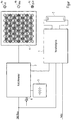
- the only figure shows a lighting arrangement with a gas discharge lamp, a ballast for this, and an emergency light module with LED light source, all controlled by a (not shown) center of a bus system.
- the sole FIGURE shows an electronic ballast which controls a gas discharge lamp 2 for illuminating an unspecified space.
- the ballast 1 draws its electrical energy from the network.
- an emergency light module 3 fed by a battery 5 becomes active and sets an LED light source 4 into operation.
- the latter is particularly well suited for emergency lighting operation, because it can be operated with low voltage, in contrast to the gas discharge lamp 2, so that conversion losses are eliminated.
- the energy efficiency of the LED light source 4 is cheaper than that of the gas discharge lamp 2, which is an important factor in battery operation.
- Such an operating parameter can be, for example, the result of a self-test of the emergency light module 3, which can be initiated by pressing a button 6 provided on the emergency light module 3.
- the self-test may, for example, refer to the state of the battery of the emergency light module.
- the optically output operating parameters can indicate operating states and / or errors of the light source.
- a self-test can be carried out beforehand by the operating device, which is triggered by an internal control and / or by external signals can be.
- An example of an error indication is an exceeding and / or falling below of a limit value by the (mains) supply voltage.
- operating data such as the number or duration of operation of the light source or a component aging can be displayed.
- These parameters can be determined by means of a counter and / or by means of this parameter determined measuring circuit, wherein the measuring circuit can perform a monitoring measurement.
- the LED light source 4 is a white light source. In the present example, it consists of three groups of LEDs. The LEDs 4a of the first group are intended to emit red light. The LEDs 4b of the second group are intended to emit blue light. And the LEDs 4c of the third group are for emitting green light. If the LEDs 4a, 4b, 4c of all three groups are driven by the emergency light module 3 for light emission, then the cumulative light emitted by them is white as intended.
- the display of the operating parameters takes place in the present case in that only a partial number of the LEDs of the LED light source is driven for the optical signal output, the way that they differ from a regular one Illuminate monochrome light or also a buzzing mixed light, which is not white.
- one or more LEDs 4c can be controlled, which are intended for the emission of monochrome green light.
- one or more LEDs 4a which are intended to emit red light, can be actuated.
- An address may be conveyed by one or more selected LEDs destined to emit one of the three colors being driven to flash / blink.
- the blinking can take place in short or long luminous phases, so that the information is transmitted, for example, with the Morse code.
- the LED light source instead of producing white light by triples of LEDs 4a, 4b, 4c designed to emit red, blue and green light, it is also possible for the LED light source to consist of only two groups of LEDs together, one of which comprises color-converted white light LEDs, and the other one for monochromatic red light emission, which supplement the color spectrum of the white light LEDs to produce a white sum light that is closer to room lighting requirements than the white light emitted only by the white light LEDs. Because white light is not monochromatic, there are many variants of it. It is important in this context that the LEDs which are intended for the emission of red light are activated for the signal output.
Landscapes
- Circuit Arrangement For Electric Light Sources In General (AREA)
- Non-Portable Lighting Devices Or Systems Thereof (AREA)
Description
- Die vorliegende Erfindung bezieht sich auf Verfahren zur optischen Signalausgabe von Betriebsparametern bei einem Betriebsgerät mit einer von diesem gesteuerten LED-Lichtquelle, die von mindestens drei LEDs gebildet ist, welche einzeln zur Emission von Licht unterschiedlicher Farbe und zusammen zur Abstrahlung von weißem Summenlicht bestimmt sind.
- Wenn nachfolgend davon die Rede, dass eine LED zur Emission von Licht einer Farbe "bestimmt" ist, so soll das bedeuten, dass die LED nur Licht dieser Farbe erzeugen kann.
- Im Bereich der Beleuchtungs- und Haustechnik sind in den letzten Jahren immer mehr Systeme entwickelt worden, bei denen verschiedenartige Leuchtmittel-Betriebsgeräte über ein Bussystem miteinander verbunden werden können. Ein Beispiel für ein derartiges standardisiertes Bussystem ist der Industriestandard DALI.
- Bei der Installation oder Änderung eines derartigen Bussystems muss einem neu hinzukommenden Teilnehmer üblicherweise eine Betriebsadresse zugewiesen werden. Diese Betriebsadresse kann sich von einer ggf. herstellerseitig vorgesehenen Ursprungsadresse in dem Gerät unterscheiden.
- Es ist bekannt, dass sich beispielsweise in der Art eines Zufallsprinzips die Busteilnehmer die Adressen innerhalb eines definierten Adressvorrats ausgelöst durch einen entsprechenden Befehl von einer Buszentrale selbst zuweisen. Da die Busadressvergabe an die Busteilnehmer nicht der zentrale Punkt der vorliegenden Erfindung ist, wird auf die einschlägig bekannten Verfahren verwiesen.
- Auf jeden Fall wird jedem Busteilnehmer nach Abschluss des Verfahrens eine Betriebsadresse zugeteilt sein bzw. hat sich jeder Busteilnehmer selbst eine Adresse aus dem definierten Adressvorrat zugewiesen. Um nunmehr im folgenden eigentlichen Betrieb der mittels des Bussystems gesteuerten Beleuchtungsanlage zielgerecht vorgehen zu können, muss in Erfahrung gebracht werden, wie die Betriebsadresse eines jeden angeschlossenen Busteilnehmers lautet. Dies erfordert viel Zeit, da ein Bediener sich physikalisch zu jedem angeschlossenen Busteilnehmer begeben muss, um dann an Ort und Stelle üblicherweise visuell die Adressvergabe zu kontrollieren. Dieser Installationsschritt ist natürlich dann besonders mühevoll, wenn die Busteilnehmer in einem Gebäude oder ggf. über mehrere Gebäude hinaus weit verteilt sind. Dies ist gerade bei sogenannten Notlichtgeräten der Fall, die also beim Ausfall einer Netzspannungsversorgung batteriegespeist eine definierte Notbeleuchtung gewährleisten sollen und die üblicherweise besonders weit voneinander beabstandet über Gebäude verteilt sind. Wenn sich also insbesondere bei Notlichtgeräten der Installateur über weite Bereiche des Installationsgebietes bewegen muss, sollte dann zumindest das In-Erfahrungbringen der vergebenen Adressen möglichst zügig vonstatten gehen.
- Die
WO 2006/136236 setzt an diesem Punkt an und schlägt vor, neben der von dem Betriebsgerät gesteuerten Lichtquelle zusätzliche optische und/oder akustische Signalgeber vorzusehen, welche die Busadresse in kodierter Form wiedergeben können. Als akustische Signalgeber können beispielsweise LEDs eingesetzt werden, die vorzugsweise mit dem Betriebsgerät verbunden sind. - Die
EP 1 098 550 A2 offenbart die Möglichkeit, den Hardware-Aufwand gegenüber dem zuletzt beschriebenen Stand der Technik zu reduzieren, für den Fall der optischen Anzeige der Betriebsdauer eines Betriebsgerätes. Dieses wird erreicht indem, der die LED-Lichtquelle bildenden RGB LEDs, die zur Abstrahlung von einfarbigem (nicht-weißem) Licht bestimmt sind, zur optischen Signalausgabe der Betriebsdauer angesteuert werden. - Die vorliegende Erfindung soll diese bekannte Anwendung erweitern, in dem weitere Betriebsparameter optisch angezeigt werden können. Die Lösung gemäß Verfahrensanspruch 1 besteht darin, dass eine Teilzahl der die LED-Lichtquelle bildenden LEDs zur Abstrahlung von nicht-weißem Licht bestimmt ist und diese Teilzahl mindestens zwei nicht-weiße LEDs aufweist, die zur Abstrahlung von einfarbigem Licht bestimmt sind, wobei wenigstens einer der mindestens zwei nicht-weißen LEDs zur Emission von rotem Licht bestimmt ist und wenigstens einer der mindestens zwei nicht-weißen LEDs zur Emission von grünem Licht bestimmt ist,wobei das Betriebsgerät die mindestens zwei nicht-weißen LEDs zur optischen Signalausgabe von Betriebsparametern des Betriebsgeräts ansteuert, wobei die optische Signalausgabe durch Blinken der mindestens zwei nicht-weißen LEDs realisiert wird, dadurch gekennzeichnet, dass einer der anzuzeigenden Betriebsparameter ein Selbsttest-Ergebnis des Betriebsgerätes ist,wobei ein positives Ergebnis des Selbsttests des Betriebsgerätes durch Blinken der wenigstens einen LED realisiert wird, die zur Emission von grünem Licht bestimmt ist,und ein negatives Ergebnis des Selbsttests des Betriebsgerätes, d.h. ein defekter Zustand, durch Blinken der wenigstens einen LED realisiert wird, die zur Emission von rotem Licht bestimmt ist.
- Durch die erfindungsgemäße Lösung sind zusätzliche optische und/oder akustische Signalgeber entbehrlich für die sichere Anzeige des Ergebnis eines Selbsttests des Betriebsgerätes.
- Schließlich betrifft die Erfindung eine Beleuchtungsanordnung gemäß Anspruch 8.
- Der die Beleuchtungsanordnung betreffenden Erfindung liegt die gleiche Aufgabe und das gleiche Lösungsprinzip wie der das eingangs beschriebene Verfahren betreffenden Erfindung. Auf die entsprechenden Ausführungen wird daher zur Vermeidung von Wiederholungen Bezug genommen.
- Die letztgenannten abhängigen Ansprüche - ebenfalls zur Vermeidung von unnötigen Wiederholungen - sollen vollinhaltlich zum Offenbarungsgehalt der Beschreibung zählen. Dennoch sollen einige besonders wichtige Ausgestaltungen nachfolgend nochmals kurz kommentiert werden.
- So sollten die zur Signalausgabe ausgewählten LEDs zur Emission einer ausgewählten Farbe bestimmt sein, sie müssen es jedoch nicht und können auch eine nichtmonochromatische Mischfarbe abstrahlen. Wesentlich ist, dass die ausgewählten LEDs ein nicht-weißes Licht Summenlicht abstrahlen, welches sich hinsichtlich seiner Färbung eindeutig von dem Weißlicht unterscheidet, das die LED-Lichtquelle bestimmungsgemäß für die Beleuchtung ihrer Umgebung ausstrahlen soll.
- Die LED-Lichtquelle kann aus drei LEDs bestehen, von denen eine erste zur Emission von rotem Licht, eine zweite zur Emission von grünem Licht und eine dritte zur Emission von blauem Licht bestimmt ist.
- Eine weitere Möglichkeit besteht darin, dass mindestens eine zur Emission von einfarbigem Licht bestimmte LED so angesteuert wird, dass sie durch kurzes und langes Aufleuchten Informationen bspw. nach dem Morsealphabet übermittelt.
- Ebenso ist es möglich, dass mindestens eine zur Emission von einfarbigem Licht bestimmte LED so angesteuert wird, das die durch Blinken dieser LED bewirkte Signalausgabe in binär oder dezimal kodierter Form erfolgt.
- Eine andere Variante kann darin bestehen, dass die zur Emission von farbigem Licht bestimmten und eine Untergruppe bildenden LEDs so angesteuert werden, das sie Zahlen, Ziffern oder sonstige Symbole darstellen, mittels welchen die Signalausgabe realisiert wird.
- In besonderer Weise eignen sich die Erfindungen zur Anzeige einer Ursprungsadresse oder einer Betriebsadresse eines Betriebsgerätes für die LED-Lichtquelle oder eine andere Lichtquelle. Über die genannte Adresse kann das Betriebsgerät von einer entfernten Zentrale aus - ggf. über ein Bussystem - für eine Signalübermittlung aufgerufen werden.
- Die Erfindung betrifft auch ein Beleuchtungssystem, aufweisend wenigstens zwei über eine Busleitung, bspw. gemäss dem DALI-Standard, angesteuerte und vorzugsweise mit einer Zentraleinheit verbundene Beleuchtungsanordnungen.
- Dabei kann jeder Beleuchtungsanordnung eine individuelle und/oder eine Gruppenadresse zuteilbar sein, wobei die bestimmte Betriebsparameter repräsentierenden Licht-Signale die zugeteilte Adresse der zugeordneten Beleuchtungsanordnung wiedergeben.
- Dabei können unterschiedliche Adressen durch Lichtsignale unterschiedlichen Spektrums, insbesondere unterschiedlicher Farbe wiedergegeben werden.
- Die Ausgabe der zugeteilten Adresse mittels der Lichtsignale kann durch einen Befehl von der Zentraleinheit her oder durch eine manuelle Benutzeraktivität auslösbar sein.
- Ein Ausführungsbeispiel zu den oben genannten Erfindungen wird nachfolgend anhand der einzigen Figur erläutert.
- Die einzige Figur zeigt
eine Beleuchtungsanordnung mit einer Gasentladungslampe, einem Vorschaltgerät für diese, sowie einem Notlichtmodul mit LED-Lichtquelle, alles von einer (nicht dargestellten) Zentrale aus über ein Bus-System gesteuert. - Die einzige Figur zeigt ein elektronisches Vorschaltgerät, welches eine Gasentladungslampe 2 zur Beleuchtung eines nicht näher spezifizierten Raumes steuert. Das Vorschaltgerät 1 bezieht seine elektrische Energie aus dem Netz.
- Wenn die Netzspannungsversorgung ausfällt, wird ein von einer Batterie 5 gespeister Notlichtmodul 3 aktiv und setzt eine LED-Lichtquelle 4 in Betrieb. Letzterer ist für den Notlichtbetrieb besonders gut geeignet, weil er mit - im Gegensatz zu der Gasentladungslampe 2 - mit Niederspannung betrieben werden kann, so dass Wandlungsverluste entfallen. Außerdem ist die Energie-Effizienz der LED-Lichtquelle 4 günstiger als die der Gasentladungslampe 2, was bei Batterie-Betrieb ein wichtiger Faktor ist.
- Das Notlichtmodul 3 ist ebenso, wie das Vorschaltgerät 2 busfähig, indem es eine Schnittstelle für einen digitalen Datenbus aufweist, an den beispielsweise ein aus dem Stand der Technik an sich gut bekannter Datenbus gemäß dem DALI-Standard angeschlossen werden kann. Es kann ein Eindrahtbus oder auch ein Mehrdrahtbus vorgesehen sein. Der DALI-Standard stellt natürlich nur ein Beispiel für das verwendete Protokoll dar. Es können andere digitale, aber auch analoge Protokolle verwendet werden.
- Die LED-Lichtquelle 4 kann bei entsprechender Dimensionierung und dann, wenn es die Rahmenbedingungen zulassen, die Beleuchtungsfunktion der Gasentladungslampe 2 mit übernehmen. Das bedeutet, dass in diesem Fall die Gasentladungslampe 2 und das Vorschaltgerät entfallen können. Die LED-Lichtquelle dient dann also sowohl zur Signalausgabe, wie auch zu Beleuchtungszwecken. Der Notlichtmodul 3 ist dann so gestaltet, dass es auch aus dem Netz betrieben werden kann und nur bei Netzausfall auf Batteriebetrieb umschaltet. Bei dieser Variante wird der mit den Erfindungen verbundene Vorteil voll ersichtlich. Er besteht darin, dass die LED-Lichtquelle 4 nicht nur zur allgemeinen Beleuchtung der Umgebung ausgebildet ist, sondern auch zur lokalen optischen Signalausgabe von Betriebsparametern, deren Kenntnis vor Ort erwünscht oder notwendig ist.
- Ein solcher Betriebsparameter kann beispielsweise das Ergebnis eines Selbsttests des Notlichtmoduls 3 sein, der durch Drücken eines an dem Notlichtmodul 3 vorgesehenen Tasters 6 eingeleitet werden kann. Der Selbsttest kann sich bspw. auf den Zustand der Batterie des Notlichtmoduls beziehen.
- Grundsätzlich können die optisch ausgegebenen Betriebsparameter Betriebszustände und/oder Fehler der Lichtquelle anzeigen. Dazu kann durch das Betriebsgerät vorher ein Selbsttest ausgeführt werden, der durch eine interne Steuerung und/oder durch externe Signale ausgelöst werden kann. Ein Beispiel für eine Fehleranzeige ist ein Über- und/oder Unterschreiten eines Grenzwerts durch die (Netz-)Versorgungsspannung.
- Weiterhin können Betriebsdaten, wie bspw. die Anzahl oder die Dauer des Betriebs der Lichtquelle oder eine Bauteilalterung angezeigt werden. Diese Parameter können mittels eines Zählers und/oder mittels eier diesen Parameter ermittelten Messschaltung ermittelt werden, wobei die Messschaltung eine Überwachungsmessung ausführen kann.
- Die LED-Lichtquelle 4 ist eine Weißlichtquelle. Sie besteht im vorliegenden Beispiel aus drei Gruppen von LEDs. Die LEDs 4a der ersten Gruppe sind zur Emission von rotem Licht bestimmt. Die LEDs 4b der zweiten Gruppe sind zur Emission von blauem Licht bestimmt. Und die LEDs 4c der dritten Gruppe sind zur Emission von grünem Licht bestimmt. Wenn die LEDs 4a, 4b, 4c aller drei Gruppen von dem Notlichtmodul 3 zur Lichtemission angesteuert werden, so ist das von ihnen abgestrahlte Summenlicht bestimmungsgemäß weiß.
- Für die Anzeige vorstehend genannten Betriebsparameter gibt es nun verschiedene Möglichkeiten, denen aber allen gemeinsam ist, dass für die Signalausgabe keine zusätzlichen Mittel erforderlich sind, wie dies im Stand der Technik (z.B.
WO 2006/136236 ) noch der Fall ist. - Die Anzeige der Betriebsparameter erfolgt im vorliegenden Fall dadurch, dass für die optische Signalausgabe nur eine Teilzahl der LEDs der LED-Lichtquelle angesteuert wird, der art, dass diese im Unterschied zu einer regulären Beleuchtung einfarbiges Licht oder auch ein Summen-Mischlicht abstrahlen, das nicht weiß ist.
- Zur Anzeige eines positiven Selbsttest-Ergebnisses des Notlichtmoduls 3 können beispielsweise eine oder mehrere LEDs 4c angesteuert werden, die zur Abstrahlung von einfarbig grünem Licht bestimmt sind. Zur Anzeige eines negativen Selbsttest-Ergebnisses (Fehler) kann dagegen eine oder mehrere LEDs 4a angesteuert werden, die zur Emission von rotem Licht bestimmt sind.
- Eine Adresse kann dadurch übermittelt werden, dass eine oder mehrere ausgewählte LEDs, die zur Abstrahlung einer der drei Farben bestimmt sind, derart angesteuert wird/werden, dass sie blinkt/blinken. Das Blinken kann in kurzen oder langen Leuchtphasen erfolgen, so dass die Information bspw. mit dem Morsealphabet übermittelt wird.
- Es ist aber auch möglich, die Information in binär oder dezimal kodierter Form auszugeben.
- Schließlich ist es auch möglich, den gewünschten Betriebsparameter direkt in Form von Ziffern, Zahlen oder sonstigen Zeichen darzustellen, indem die entsprechenden LEDs in der LED-Lichtquelle unter Beachtung der Hauptregel angesteuert werden, dass kein Summenlicht erzeugt werden darf, welches mit dem weißen Licht verwechselt werden kann, dass für die allgemeine Beleuchtung vorgesehen ist.
- Statt weißes Licht durch Tripel von LEDs 4a, 4b, 4c zu erzeugen, die zur Emission von rotem, blauem und grünem Licht bestimmt sind, besteht auch die Möglichkeit, die LED-Lichtquelle aus nur zwei Gruppen von LEDs zusammenzustellen, von denen eine farbstoffkonvertierte Weißlicht-LEDs umfasst, und die andere zur Abstrahlung von monochromem rotem Licht bestimmte LEDs, die das Farbspektrum der Weißlicht-LEDs so ergänzen, dass ein weißes Summenlicht erzeugt wird, welches den Anforderungen für eine Raumbeleuchtung näher kommt, als das nur von den Weißlicht-LEDs abgestrahlte weiße Licht. Da weißes Licht nicht monochromatisch ist, gibt es viele Varianten davon. Wichtig ist in diesem Zusammenhang, dass für die Signalausgabe die LEDs angesteuert werden, die zur Emission von rotem Licht bestimmt sind.
Claims (10)
- Verfahren zur optischen Signalausgabe von Betriebsparametern bei einem Betriebsgerät (3) mit einer von diesem Betriebsgerät (3) gesteuerten LED-Lichtquelle (4), die aus mindestens drei LEDs (4a, 4b, 4c) gebildet ist,
wobei die mindestens drei LEDs einzeln zur Emission von Licht unterschiedlicher Farbe und zusammen zur Abstrahlung von weißem Summenlicht bestimmt sind, wobei eine Teilzahl der die LED-Lichtquelle (4) bildenden LEDs (4a, 4b, 4c) zur Abstrahlung von nicht-weißem Licht bestimmt ist und diese Teilzahl mindestens zwei nicht-weiße LEDs aufweist, die zur Abstrahlung von einfarbigem Licht bestimmt sind, wobei wenigstens einer der mindestens zwei nicht-weißen LEDs (4a) zur Emission von rotem Licht bestimmt ist und wenigstens einer der mindestens zwei nicht-weißen LEDs (4c) zur Emission von grünem Licht bestimmt ist,
wobei das Betriebsgerät die mindestens zwei nicht-weißen LEDs zur optischen Signalausgabe von Betriebsparametern des Betriebsgeräts ansteuert, wobei die optische Signalausgabe durch Blinken der mindestens zwei nicht-weißen LEDs (4a, 4b, 4c) realisiert wird,
dadurch gekennzeichnet,
dass einer der anzuzeigenden Betriebsparameter ein Selbsttest-Ergebnis des Betriebsgerätes (3) ist,
wobei ein positives Ergebnis des Selbsttests des Betriebsgerätes (3) durch Blinken der wenigstens einen LED (4c) realisiert wird, die zur Emission von grünem Licht bestimmt ist,
und ein negatives Ergebnis des Selbsttests des Betriebsgerätes (3), d.h. ein defekter Zustand, durch Blinken der wenigstens einen LED (4a) realisiert wird, die zur Emission von rotem Licht bestimmt ist. - Verfahren nach Anspruch 1,
wobei weitere anzuzeigende Betriebsparameter ausgewählt sind aus:- Fehlerzuständen hinsichtlich der Versorgungsspannung, und/oder- Spannungen an einem Bauteil des Betriebsgeräts, wie bspw. eine Batteriespannung. - Verfahren nach einem der Ansprüche 1 oder 2,
wobei die LED-Lichtquelle (4) neben der optischen Signalausgabe auch zur Beleuchtung, insbesondere Notbeleuchtung verwendet wird. - Verfahren nach einem der vorher stehenden Ansprüche,
dadurch gekennzeichnet,
dass die optische Signalausgabe durch vorzugsweise getaktete Modulation der mindestens zwei nicht-weissen LED (4a, 4b, 4c) realisiert wird, die zur Abstrahlung von einfarbigem Licht bestimmt sind. - Verfahren nach Anspruch 1, dadurch gekennzeichnet, dass ein weiterer anzuzeigender Betriebsparameter eine Ursprungsadresse oder eine Betriebsadresse ist, über die das Betriebsgerät (3) von einer entfernten Zentrale aus ggf. über ein Bussystem für eine Signalübermittlung aufgerufen werden kann.
- Beleuchtungsanordnung mit einem Betriebsgerät (3) und mit einer von diesem Betriebsgerät gesteuerten LED-Lichtquelle (4), die aus mindestens drei LEDs (4a, 4b, 4c) gebildet ist,
wobei die mindestens drei LEDs einzeln Licht unterschiedlicher Farbe emittieren und zusammen ein weißes Summenlicht abstrahlen,
wobei eine Teilzahl der die LED-Lichtquelle (4) bildenden LEDs (4a, 4b, 4c) zur Abstrahlung von nicht-weißem Licht bestimmt ist und diese Teilzahl mindestens zwei nicht-weißen LEDs aufweist, die zur Abstrahlung von einfarbigem Licht bestimmt sind, wobei wenigstens einer der mindestens zwei nicht-weißen LEDs (4a) zur Emission von rotem Licht bestimmt ist und wenigstens einer der mindestens zwei nicht-weißen LEDs (4c) zur Emission von grünem Licht bestimmt ist, und
wobei das Betriebsgerät (3) ausgestaltet ist, die mindestens zwei nicht-weißen LEDs so anzusteuern, dass diese bestimmte Betriebsparameter des Betriebsgeräts (3) repräsentierende Licht-Signale abgeben, wobei die Abgabe der Licht-Signale durch Blinken der mindestens zwei nicht-weißen LEDs (4a, 4b, 4c) realisiert wird,
dadurch gekennzeichnet,
dass das Betriebsgerät (3) ausgestaltet ist, als einer der Betriebsparameter ein Selbsttest-Ergebnis des Betriebsgerätes anzuzeigen,
wobei ein positives Ergebnis des Selbsttests des Betriebsgerätes (3) durch Blinken der wenigstens einen LED (4c) realisiert wird, die zur Emission von grünem Licht bestimmt ist, und
wobei ein negatives Ergebnis des Selbsttests des Betriebsgerätes (3), d.h. ein defekter Zustand, durch Blinken der wenigstens einen LED (4a) realisiert wird, die zur Emission von rotem Licht bestimmt ist. - Beleuchtungssystem,
aufweisend wenigstens zwei über eine Busleitung, bspw. gemäss dem DALI-Standard, angesteuerte und vorzugsweise mit einer Zentraleinheit verbundene Beleuchtungsanordnungen nach Anspruch 6. - Beleuchtungssystem nach Anspruch 7,
wobei jede Beleuchtungsanordnung ausgestaltet ist, eine individuelle Adresse und/oder eine Gruppenadresse zugeteilt zu bekommen,
wobei die bestimmte Betriebsparameter repräsentierenden Licht-Signale die zugeteilte Adresse der zugeordneten Beleuchtungsanordnung wiedergeben. - Beleuchtungssystem nach Anspruch 8,
wobei die bestimmte Betriebsparameter repräsentierenden Licht-Signale unterschiedliche Adressen durch Lichtsignale unterschiedlichen Spektrums, insbesondere unterschiedlicher Farbe wiedergeben. - Beleuchtungssystem nach einem der Ansprüche 8 oder 9,
wobei das Beleuchtungssystem ausgestaltet ist, die Ausgabe der zugeteilten Adresse mittels der Lichtsignale durch einen Befehl einer Zentraleinheit des Beleuchtungssystems her oder durch eine manuelle Benutzeraktivität auszulösen.
Applications Claiming Priority (4)
| Application Number | Priority Date | Filing Date | Title |
|---|---|---|---|
| DE102009057015 | 2009-12-04 | ||
| DE102009055415 | 2009-12-30 | ||
| DE102010000902A DE102010000902A1 (de) | 2009-12-04 | 2010-01-14 | Optische Signalausgabe von Betriebsparametern bei einer LED-Beleuchtung |
| PCT/EP2010/068803 WO2011067367A2 (de) | 2009-12-04 | 2010-12-03 | Optische signalausgabe von betriebsparametern bei einer led-beleuchtung |
Publications (2)
| Publication Number | Publication Date |
|---|---|
| EP2508046A2 EP2508046A2 (de) | 2012-10-10 |
| EP2508046B1 true EP2508046B1 (de) | 2019-04-03 |
Family
ID=43972455
Family Applications (1)
| Application Number | Title | Priority Date | Filing Date |
|---|---|---|---|
| EP10790377.5A Active EP2508046B1 (de) | 2009-12-04 | 2010-12-03 | Optische signalausgabe von betriebsparametern bei einer led-beleuchtung |
Country Status (5)
| Country | Link |
|---|---|
| US (1) | US8901822B2 (de) |
| EP (1) | EP2508046B1 (de) |
| CN (1) | CN102668715B (de) |
| DE (2) | DE102010000902A1 (de) |
| WO (1) | WO2011067367A2 (de) |
Families Citing this family (7)
| Publication number | Priority date | Publication date | Assignee | Title |
|---|---|---|---|---|
| AT510826B1 (de) * | 2010-11-10 | 2016-05-15 | Din Dietmar Nocker Facilityman Gmbh | Verfahren zur initialisierung einer notbeleuchtungsanlage |
| EP2839720A4 (de) | 2012-04-19 | 2016-03-02 | Cooper Technologies Co | Notstrombatteriewandler |
| US9328883B1 (en) * | 2012-05-07 | 2016-05-03 | Cooper Technologies Company | Providing power to remote emergency light fixtures |
| DE102015217398B4 (de) | 2015-09-11 | 2025-08-28 | Tridonic Gmbh & Co Kg | Belechtungsanordnung, Beleuchtungssystem und Verfahren zum Betreiben eines Beleuchtungssystems für einen Gebäudeteil |
| DE102020100399A1 (de) * | 2020-01-10 | 2021-07-15 | Zumtobel Lighting Gmbh | Leuchte mit integriertem Selbsttest |
| CN116634254A (zh) * | 2022-02-11 | 2023-08-22 | 深超光电(深圳)有限公司 | 成像系统及光学装置 |
| CN116453272A (zh) * | 2023-03-31 | 2023-07-18 | 江苏海马通信科技有限公司 | 基于物联网技术的遥控双语智能信号灯 |
Citations (5)
| Publication number | Priority date | Publication date | Assignee | Title |
|---|---|---|---|---|
| EP1098550A2 (de) * | 1999-11-05 | 2001-05-09 | Avix Inc. | Ledleuchte |
| GB2432951A (en) * | 2003-09-19 | 2007-06-06 | Saf T Glo Ltd | Networked devices which perform self test check |
| WO2010086758A1 (en) * | 2009-02-02 | 2010-08-05 | Koninklijke Philips Electronics, N.V. | Coded warning system for lighting units |
| WO2010116289A1 (en) * | 2009-04-08 | 2010-10-14 | Koninklijke Philips Electronics N.V. | Lighting device having status indication by modulated light |
| WO2013089659A2 (en) * | 2010-10-22 | 2013-06-20 | Cree, Inc. | Solid state lighting devices providing visible alert signals in general illumination applications and related methods of operation |
Family Cites Families (13)
| Publication number | Priority date | Publication date | Assignee | Title |
|---|---|---|---|---|
| CN2397559Y (zh) * | 1999-11-24 | 2000-09-20 | 稳态企业有限公司 | 具光影变化的多功能广告牌 |
| US7642730B2 (en) * | 2000-04-24 | 2010-01-05 | Philips Solid-State Lighting Solutions, Inc. | Methods and apparatus for conveying information via color of light |
| US7397068B2 (en) * | 2003-12-23 | 2008-07-08 | Tessera, Inc. | Solid state lighting device |
| CA2496661C (en) * | 2004-02-19 | 2009-05-19 | Oz Optics Ltd. | Light source control system |
| US7592713B2 (en) * | 2005-02-25 | 2009-09-22 | Marathon Coach, Inc. | Electrical system for controlling coach resources |
| DE102005028206B4 (de) | 2005-06-17 | 2018-05-17 | Tridonic Gmbh & Co Kg | Ermittlung der Busadresse eines Teilnehmers in einem Beleuchtungs-Bussystem |
| DE102005057068A1 (de) * | 2005-11-30 | 2007-06-06 | Zumtobel Lighting Gmbh | Steuerungssystem für mehrere verteilt angeordnete Verbraucher, insbesondere für Lampenbetriebsgeräte, sowie Verfahren zur Inbetriebnahme |
| EP1989925A1 (de) * | 2006-02-23 | 2008-11-12 | TIR Technology LP | System und verfahren zur lichtquellenidentifikation |
| US7737640B2 (en) * | 2007-02-12 | 2010-06-15 | Abl Ip Holding Llc | Emergency lighting system |
| CN201059430Y (zh) * | 2007-03-13 | 2008-05-14 | 士商(上海)机械有限公司 | Led工作灯 |
| DE202007005495U1 (de) * | 2007-04-13 | 2007-08-30 | Werma Signaltechnik Gmbh + Co. Kg | Warnleuchtsäule |
| DE102007052377B4 (de) * | 2007-10-31 | 2015-04-02 | Werma Holding Gmbh + Co. Kg | Warnleuchte zur optischen Anzeige von wenigstens einem Betriebszustand |
| KR20110101915A (ko) * | 2010-03-10 | 2011-09-16 | 한국원자력연구원 | 축전지의 잔여용량 지시기능을 갖는 유도등 및 비상조명등 |
-
2010
- 2010-01-14 DE DE102010000902A patent/DE102010000902A1/de not_active Withdrawn
- 2010-12-03 EP EP10790377.5A patent/EP2508046B1/de active Active
- 2010-12-03 WO PCT/EP2010/068803 patent/WO2011067367A2/de not_active Ceased
- 2010-12-03 DE DE112010004654T patent/DE112010004654A5/de not_active Ceased
- 2010-12-03 US US13/513,358 patent/US8901822B2/en active Active
- 2010-12-03 CN CN201080054153.4A patent/CN102668715B/zh not_active Expired - Fee Related
Patent Citations (6)
| Publication number | Priority date | Publication date | Assignee | Title |
|---|---|---|---|---|
| EP1098550A2 (de) * | 1999-11-05 | 2001-05-09 | Avix Inc. | Ledleuchte |
| GB2432951A (en) * | 2003-09-19 | 2007-06-06 | Saf T Glo Ltd | Networked devices which perform self test check |
| WO2010086758A1 (en) * | 2009-02-02 | 2010-08-05 | Koninklijke Philips Electronics, N.V. | Coded warning system for lighting units |
| WO2010116289A1 (en) * | 2009-04-08 | 2010-10-14 | Koninklijke Philips Electronics N.V. | Lighting device having status indication by modulated light |
| WO2013089659A2 (en) * | 2010-10-22 | 2013-06-20 | Cree, Inc. | Solid state lighting devices providing visible alert signals in general illumination applications and related methods of operation |
| EP2636285A2 (de) * | 2010-10-22 | 2013-09-11 | Cree, Inc. | Festkörperabbildungsvorrichtungen zur ausgabe sichtbarer alarmsignale in allgemeinen beleuchtungsanwendungen und betriebsverfahren dafür |
Also Published As
| Publication number | Publication date |
|---|---|
| EP2508046A2 (de) | 2012-10-10 |
| US20130043794A1 (en) | 2013-02-21 |
| DE112010004654A5 (de) | 2012-10-31 |
| CN102668715B (zh) | 2015-09-30 |
| CN102668715A (zh) | 2012-09-12 |
| WO2011067367A3 (de) | 2011-08-11 |
| WO2011067367A2 (de) | 2011-06-09 |
| US8901822B2 (en) | 2014-12-02 |
| DE102010000902A1 (de) | 2011-06-09 |
Similar Documents
| Publication | Publication Date | Title |
|---|---|---|
| EP2508046B1 (de) | Optische signalausgabe von betriebsparametern bei einer led-beleuchtung | |
| DE4327809C2 (de) | Verfahren zum Adressieren von mit einer zentralen Steuereinheit verbundenen elektronischen Vorschaltgeräten | |
| EP2364574B1 (de) | Adressvergabe für busfähige leuchtmittel-betriebsgeräte insbesondere für leds | |
| EP1555859A1 (de) | Ansteuerung von Leuchtmittel-Betriebsgeräten über einen modulierten DC-Bus | |
| DE102009050733A1 (de) | Verfahren und System zur Vergabe von Betriebsadressen für Lichtquellen oder Leuchten | |
| EP1587347B1 (de) | Vorrichtung zur Steuerung einer Vielzahl von Leuchten | |
| DE102013016386B4 (de) | Vorrichtung und Verfahren zur Einstellung mehrfarbiger Lichtszenen in Kfz | |
| EP2204076B1 (de) | Verfahren zur konfiguration eines beleuchtungs-bussystems | |
| WO2012163641A1 (de) | Signalisierungsvorrichtung und sensorvorrichtung | |
| EP3120670A1 (de) | Zentraleinheit eines bussystems, bussystem und verfahren zur lokalisierung von busteilnehmern | |
| EP1665903A1 (de) | Steuersystem f r mehrere verteilt angeordnete lampenbetriebs ger te sowie verfahren zum initialisieren eines derartigen s teuersystems | |
| EP2553674A1 (de) | Verfahren zur ausleuchtung eines lichtkastens | |
| WO2006136236A1 (de) | Ermittlung der busadresse eines teilnehmers in einem beleuchtungs-bussystem | |
| EP2280585B1 (de) | Verfahren zur Einstellung der Ansteuerung mehrerer Leuchten | |
| DE102009024412A1 (de) | Verfahren zum Betreiben eines Beleuchtungssystems, Computerprogramm und Beleuchtungssystem | |
| EP2176584B1 (de) | Leuchte für mindestens eine led und sender zur erzeugung eines funksignals für eine derartige leuchte | |
| DE102010055296A1 (de) | Leuchtmittel mit Farbortdimmung | |
| EP1624729B1 (de) | Verfahren zur Inbetriebnahme eines Beleuchtungssystems und Inbetriebnahmegerät | |
| EP2745631A2 (de) | Verfahren zur adressierung von leuchtmittelbetriebsgeräten | |
| EP3965365B1 (de) | Basismodul eines netzwerkaufbaus sowie netzwerkaufbau und verfahren zum konfigurieren eines erweiterungsmoduls des netzwerkaufbaus | |
| DE202008004399U1 (de) | Mehrfarben-Beleuchtungsvorrichtung | |
| DE102020123334B4 (de) | Erweiterungsmodul zur Funktionserweiterung eines Netzwerkaufbaus | |
| DE112011100662B4 (de) | Verfahren und Beleuchtungssystem zur Beleuchtung eines Lichtkastens | |
| EP2278861A1 (de) | Zentrale Versorgung über mehrere DC-Ausgangskreise | |
| EP3764746A1 (de) | Betriebsgerät |
Legal Events
| Date | Code | Title | Description |
|---|---|---|---|
| PUAI | Public reference made under article 153(3) epc to a published international application that has entered the european phase |
Free format text: ORIGINAL CODE: 0009012 |
|
| 17P | Request for examination filed |
Effective date: 20120601 |
|
| AK | Designated contracting states |
Kind code of ref document: A2 Designated state(s): AL AT BE BG CH CY CZ DE DK EE ES FI FR GB GR HR HU IE IS IT LI LT LU LV MC MK MT NL NO PL PT RO RS SE SI SK SM TR |
|
| DAX | Request for extension of the european patent (deleted) | ||
| STAA | Information on the status of an ep patent application or granted ep patent |
Free format text: STATUS: EXAMINATION IS IN PROGRESS |
|
| 17Q | First examination report despatched |
Effective date: 20170118 |
|
| GRAP | Despatch of communication of intention to grant a patent |
Free format text: ORIGINAL CODE: EPIDOSNIGR1 |
|
| STAA | Information on the status of an ep patent application or granted ep patent |
Free format text: STATUS: GRANT OF PATENT IS INTENDED |
|
| INTG | Intention to grant announced |
Effective date: 20190108 |
|
| RIN1 | Information on inventor provided before grant (corrected) |
Inventor name: HARTMANN, MARTIN Inventor name: KEARS, JOHN |
|
| GRAS | Grant fee paid |
Free format text: ORIGINAL CODE: EPIDOSNIGR3 |
|
| GRAA | (expected) grant |
Free format text: ORIGINAL CODE: 0009210 |
|
| STAA | Information on the status of an ep patent application or granted ep patent |
Free format text: STATUS: THE PATENT HAS BEEN GRANTED |
|
| AK | Designated contracting states |
Kind code of ref document: B1 Designated state(s): AL AT BE BG CH CY CZ DE DK EE ES FI FR GB GR HR HU IE IS IT LI LT LU LV MC MK MT NL NO PL PT RO RS SE SI SK SM TR |
|
| REG | Reference to a national code |
Ref country code: GB Ref legal event code: FG4D Free format text: NOT ENGLISH |
|
| REG | Reference to a national code |
Ref country code: CH Ref legal event code: EP Ref country code: AT Ref legal event code: REF Ref document number: 1117375 Country of ref document: AT Kind code of ref document: T Effective date: 20190415 |
|
| REG | Reference to a national code |
Ref country code: DE Ref legal event code: R096 Ref document number: 502010015913 Country of ref document: DE |
|
| REG | Reference to a national code |
Ref country code: IE Ref legal event code: FG4D Free format text: LANGUAGE OF EP DOCUMENT: GERMAN |
|
| REG | Reference to a national code |
Ref country code: NL Ref legal event code: MP Effective date: 20190403 |
|
| REG | Reference to a national code |
Ref country code: LT Ref legal event code: MG4D |
|
| PG25 | Lapsed in a contracting state [announced via postgrant information from national office to epo] |
Ref country code: NL Free format text: LAPSE BECAUSE OF FAILURE TO SUBMIT A TRANSLATION OF THE DESCRIPTION OR TO PAY THE FEE WITHIN THE PRESCRIBED TIME-LIMIT Effective date: 20190403 |
|
| REG | Reference to a national code |
Ref country code: DE Ref legal event code: R084 Ref document number: 502010015913 Country of ref document: DE |
|
| PG25 | Lapsed in a contracting state [announced via postgrant information from national office to epo] |
Ref country code: CZ Free format text: LAPSE BECAUSE OF FAILURE TO SUBMIT A TRANSLATION OF THE DESCRIPTION OR TO PAY THE FEE WITHIN THE PRESCRIBED TIME-LIMIT Effective date: 20190403 Ref country code: NO Free format text: LAPSE BECAUSE OF FAILURE TO SUBMIT A TRANSLATION OF THE DESCRIPTION OR TO PAY THE FEE WITHIN THE PRESCRIBED TIME-LIMIT Effective date: 20190703 Ref country code: PT Free format text: LAPSE BECAUSE OF FAILURE TO SUBMIT A TRANSLATION OF THE DESCRIPTION OR TO PAY THE FEE WITHIN THE PRESCRIBED TIME-LIMIT Effective date: 20190803 Ref country code: FI Free format text: LAPSE BECAUSE OF FAILURE TO SUBMIT A TRANSLATION OF THE DESCRIPTION OR TO PAY THE FEE WITHIN THE PRESCRIBED TIME-LIMIT Effective date: 20190403 Ref country code: AL Free format text: LAPSE BECAUSE OF FAILURE TO SUBMIT A TRANSLATION OF THE DESCRIPTION OR TO PAY THE FEE WITHIN THE PRESCRIBED TIME-LIMIT Effective date: 20190403 Ref country code: SE Free format text: LAPSE BECAUSE OF FAILURE TO SUBMIT A TRANSLATION OF THE DESCRIPTION OR TO PAY THE FEE WITHIN THE PRESCRIBED TIME-LIMIT Effective date: 20190403 Ref country code: HR Free format text: LAPSE BECAUSE OF FAILURE TO SUBMIT A TRANSLATION OF THE DESCRIPTION OR TO PAY THE FEE WITHIN THE PRESCRIBED TIME-LIMIT Effective date: 20190403 Ref country code: ES Free format text: LAPSE BECAUSE OF FAILURE TO SUBMIT A TRANSLATION OF THE DESCRIPTION OR TO PAY THE FEE WITHIN THE PRESCRIBED TIME-LIMIT Effective date: 20190403 Ref country code: LT Free format text: LAPSE BECAUSE OF FAILURE TO SUBMIT A TRANSLATION OF THE DESCRIPTION OR TO PAY THE FEE WITHIN THE PRESCRIBED TIME-LIMIT Effective date: 20190403 |
|
| PG25 | Lapsed in a contracting state [announced via postgrant information from national office to epo] |
Ref country code: RS Free format text: LAPSE BECAUSE OF FAILURE TO SUBMIT A TRANSLATION OF THE DESCRIPTION OR TO PAY THE FEE WITHIN THE PRESCRIBED TIME-LIMIT Effective date: 20190403 Ref country code: BG Free format text: LAPSE BECAUSE OF FAILURE TO SUBMIT A TRANSLATION OF THE DESCRIPTION OR TO PAY THE FEE WITHIN THE PRESCRIBED TIME-LIMIT Effective date: 20190703 Ref country code: PL Free format text: LAPSE BECAUSE OF FAILURE TO SUBMIT A TRANSLATION OF THE DESCRIPTION OR TO PAY THE FEE WITHIN THE PRESCRIBED TIME-LIMIT Effective date: 20190403 Ref country code: LV Free format text: LAPSE BECAUSE OF FAILURE TO SUBMIT A TRANSLATION OF THE DESCRIPTION OR TO PAY THE FEE WITHIN THE PRESCRIBED TIME-LIMIT Effective date: 20190403 Ref country code: GR Free format text: LAPSE BECAUSE OF FAILURE TO SUBMIT A TRANSLATION OF THE DESCRIPTION OR TO PAY THE FEE WITHIN THE PRESCRIBED TIME-LIMIT Effective date: 20190704 |
|
| PG25 | Lapsed in a contracting state [announced via postgrant information from national office to epo] |
Ref country code: IS Free format text: LAPSE BECAUSE OF FAILURE TO SUBMIT A TRANSLATION OF THE DESCRIPTION OR TO PAY THE FEE WITHIN THE PRESCRIBED TIME-LIMIT Effective date: 20190803 |
|
| REG | Reference to a national code |
Ref country code: DE Ref legal event code: R097 Ref document number: 502010015913 Country of ref document: DE |
|
| PG25 | Lapsed in a contracting state [announced via postgrant information from national office to epo] |
Ref country code: RO Free format text: LAPSE BECAUSE OF FAILURE TO SUBMIT A TRANSLATION OF THE DESCRIPTION OR TO PAY THE FEE WITHIN THE PRESCRIBED TIME-LIMIT Effective date: 20190403 Ref country code: DK Free format text: LAPSE BECAUSE OF FAILURE TO SUBMIT A TRANSLATION OF THE DESCRIPTION OR TO PAY THE FEE WITHIN THE PRESCRIBED TIME-LIMIT Effective date: 20190403 Ref country code: EE Free format text: LAPSE BECAUSE OF FAILURE TO SUBMIT A TRANSLATION OF THE DESCRIPTION OR TO PAY THE FEE WITHIN THE PRESCRIBED TIME-LIMIT Effective date: 20190403 Ref country code: SK Free format text: LAPSE BECAUSE OF FAILURE TO SUBMIT A TRANSLATION OF THE DESCRIPTION OR TO PAY THE FEE WITHIN THE PRESCRIBED TIME-LIMIT Effective date: 20190403 |
|
| PLBE | No opposition filed within time limit |
Free format text: ORIGINAL CODE: 0009261 |
|
| STAA | Information on the status of an ep patent application or granted ep patent |
Free format text: STATUS: NO OPPOSITION FILED WITHIN TIME LIMIT |
|
| PG25 | Lapsed in a contracting state [announced via postgrant information from national office to epo] |
Ref country code: IT Free format text: LAPSE BECAUSE OF FAILURE TO SUBMIT A TRANSLATION OF THE DESCRIPTION OR TO PAY THE FEE WITHIN THE PRESCRIBED TIME-LIMIT Effective date: 20190403 Ref country code: SM Free format text: LAPSE BECAUSE OF FAILURE TO SUBMIT A TRANSLATION OF THE DESCRIPTION OR TO PAY THE FEE WITHIN THE PRESCRIBED TIME-LIMIT Effective date: 20190403 |
|
| 26N | No opposition filed |
Effective date: 20200106 |
|
| PG25 | Lapsed in a contracting state [announced via postgrant information from national office to epo] |
Ref country code: TR Free format text: LAPSE BECAUSE OF FAILURE TO SUBMIT A TRANSLATION OF THE DESCRIPTION OR TO PAY THE FEE WITHIN THE PRESCRIBED TIME-LIMIT Effective date: 20190403 |
|
| PGFP | Annual fee paid to national office [announced via postgrant information from national office to epo] |
Ref country code: AT Payment date: 20191220 Year of fee payment: 10 |
|
| PG25 | Lapsed in a contracting state [announced via postgrant information from national office to epo] |
Ref country code: SI Free format text: LAPSE BECAUSE OF FAILURE TO SUBMIT A TRANSLATION OF THE DESCRIPTION OR TO PAY THE FEE WITHIN THE PRESCRIBED TIME-LIMIT Effective date: 20190403 |
|
| REG | Reference to a national code |
Ref country code: CH Ref legal event code: PL |
|
| REG | Reference to a national code |
Ref country code: BE Ref legal event code: MM Effective date: 20191231 |
|
| PG25 | Lapsed in a contracting state [announced via postgrant information from national office to epo] |
Ref country code: MC Free format text: LAPSE BECAUSE OF FAILURE TO SUBMIT A TRANSLATION OF THE DESCRIPTION OR TO PAY THE FEE WITHIN THE PRESCRIBED TIME-LIMIT Effective date: 20190403 |
|
| PG25 | Lapsed in a contracting state [announced via postgrant information from national office to epo] |
Ref country code: IE Free format text: LAPSE BECAUSE OF NON-PAYMENT OF DUE FEES Effective date: 20191203 Ref country code: LU Free format text: LAPSE BECAUSE OF NON-PAYMENT OF DUE FEES Effective date: 20191203 |
|
| PG25 | Lapsed in a contracting state [announced via postgrant information from national office to epo] |
Ref country code: CH Free format text: LAPSE BECAUSE OF NON-PAYMENT OF DUE FEES Effective date: 20191231 Ref country code: BE Free format text: LAPSE BECAUSE OF NON-PAYMENT OF DUE FEES Effective date: 20191231 Ref country code: LI Free format text: LAPSE BECAUSE OF NON-PAYMENT OF DUE FEES Effective date: 20191231 |
|
| PGFP | Annual fee paid to national office [announced via postgrant information from national office to epo] |
Ref country code: GB Payment date: 20201228 Year of fee payment: 11 Ref country code: FR Payment date: 20201229 Year of fee payment: 11 |
|
| PG25 | Lapsed in a contracting state [announced via postgrant information from national office to epo] |
Ref country code: CY Free format text: LAPSE BECAUSE OF FAILURE TO SUBMIT A TRANSLATION OF THE DESCRIPTION OR TO PAY THE FEE WITHIN THE PRESCRIBED TIME-LIMIT Effective date: 20190403 |
|
| PG25 | Lapsed in a contracting state [announced via postgrant information from national office to epo] |
Ref country code: MT Free format text: LAPSE BECAUSE OF FAILURE TO SUBMIT A TRANSLATION OF THE DESCRIPTION OR TO PAY THE FEE WITHIN THE PRESCRIBED TIME-LIMIT Effective date: 20190403 Ref country code: HU Free format text: LAPSE BECAUSE OF FAILURE TO SUBMIT A TRANSLATION OF THE DESCRIPTION OR TO PAY THE FEE WITHIN THE PRESCRIBED TIME-LIMIT; INVALID AB INITIO Effective date: 20101203 |
|
| REG | Reference to a national code |
Ref country code: AT Ref legal event code: MM01 Ref document number: 1117375 Country of ref document: AT Kind code of ref document: T Effective date: 20201203 |
|
| PG25 | Lapsed in a contracting state [announced via postgrant information from national office to epo] |
Ref country code: AT Free format text: LAPSE BECAUSE OF NON-PAYMENT OF DUE FEES Effective date: 20201203 |
|
| PG25 | Lapsed in a contracting state [announced via postgrant information from national office to epo] |
Ref country code: MK Free format text: LAPSE BECAUSE OF FAILURE TO SUBMIT A TRANSLATION OF THE DESCRIPTION OR TO PAY THE FEE WITHIN THE PRESCRIBED TIME-LIMIT Effective date: 20190403 |
|
| GBPC | Gb: european patent ceased through non-payment of renewal fee |
Effective date: 20211203 |
|
| PG25 | Lapsed in a contracting state [announced via postgrant information from national office to epo] |
Ref country code: GB Free format text: LAPSE BECAUSE OF NON-PAYMENT OF DUE FEES Effective date: 20211203 |
|
| PG25 | Lapsed in a contracting state [announced via postgrant information from national office to epo] |
Ref country code: FR Free format text: LAPSE BECAUSE OF NON-PAYMENT OF DUE FEES Effective date: 20211231 |
|
| P01 | Opt-out of the competence of the unified patent court (upc) registered |
Effective date: 20230530 |
|
| PGFP | Annual fee paid to national office [announced via postgrant information from national office to epo] |
Ref country code: DE Payment date: 20241227 Year of fee payment: 15 |