EP2508765A1 - Klemme - Google Patents
Klemme Download PDFInfo
- Publication number
- EP2508765A1 EP2508765A1 EP10832968A EP10832968A EP2508765A1 EP 2508765 A1 EP2508765 A1 EP 2508765A1 EP 10832968 A EP10832968 A EP 10832968A EP 10832968 A EP10832968 A EP 10832968A EP 2508765 A1 EP2508765 A1 EP 2508765A1
- Authority
- EP
- European Patent Office
- Prior art keywords
- clip
- insertion hole
- protrusion
- locking
- pressing
- Prior art date
- Legal status (The legal status is an assumption and is not a legal conclusion. Google has not performed a legal analysis and makes no representation as to the accuracy of the status listed.)
- Withdrawn
Links
- 238000003780 insertion Methods 0.000 claims abstract description 128
- 230000037431 insertion Effects 0.000 claims abstract description 128
- 239000000463 material Substances 0.000 claims abstract description 4
- 239000011347 resin Substances 0.000 claims abstract description 4
- 229920005989 resin Polymers 0.000 claims abstract description 4
- 230000002093 peripheral effect Effects 0.000 claims description 8
- 230000003247 decreasing effect Effects 0.000 claims description 2
- 230000008878 coupling Effects 0.000 description 9
- 238000010168 coupling process Methods 0.000 description 9
- 238000005859 coupling reaction Methods 0.000 description 9
- 238000010586 diagram Methods 0.000 description 7
- 230000002829 reductive effect Effects 0.000 description 5
- 238000006243 chemical reaction Methods 0.000 description 3
- 230000006835 compression Effects 0.000 description 2
- 238000007906 compression Methods 0.000 description 2
- 230000005489 elastic deformation Effects 0.000 description 2
- 230000000452 restraining effect Effects 0.000 description 2
- 230000000717 retained effect Effects 0.000 description 2
- 239000003381 stabilizer Substances 0.000 description 2
- 229930182556 Polyacetal Natural products 0.000 description 1
- 230000002411 adverse Effects 0.000 description 1
- 230000000694 effects Effects 0.000 description 1
- 239000002184 metal Substances 0.000 description 1
- 239000007769 metal material Substances 0.000 description 1
- 238000000034 method Methods 0.000 description 1
- 230000000149 penetrating effect Effects 0.000 description 1
- 229920006324 polyoxymethylene Polymers 0.000 description 1
Images


Classifications
-
- F—MECHANICAL ENGINEERING; LIGHTING; HEATING; WEAPONS; BLASTING
- F16—ENGINEERING ELEMENTS AND UNITS; GENERAL MEASURES FOR PRODUCING AND MAINTAINING EFFECTIVE FUNCTIONING OF MACHINES OR INSTALLATIONS; THERMAL INSULATION IN GENERAL
- F16B—DEVICES FOR FASTENING OR SECURING CONSTRUCTIONAL ELEMENTS OR MACHINE PARTS TOGETHER, e.g. NAILS, BOLTS, CIRCLIPS, CLAMPS, CLIPS OR WEDGES; JOINTS OR JOINTING
- F16B21/00—Means for preventing relative axial movement of a pin, spigot, shaft or the like and a member surrounding it; Stud-and-socket releasable fastenings
- F16B21/10—Means for preventing relative axial movement of a pin, spigot, shaft or the like and a member surrounding it; Stud-and-socket releasable fastenings by separate parts
- F16B21/12—Means for preventing relative axial movement of a pin, spigot, shaft or the like and a member surrounding it; Stud-and-socket releasable fastenings by separate parts with locking-pins or split-pins thrust into holes
- F16B21/125—Means for preventing relative axial movement of a pin, spigot, shaft or the like and a member surrounding it; Stud-and-socket releasable fastenings by separate parts with locking-pins or split-pins thrust into holes radially resilient or with a snap-action member, e.g. elastic tooth, pawl with spring, resilient coil or wire
-
- B—PERFORMING OPERATIONS; TRANSPORTING
- B60—VEHICLES IN GENERAL
- B60R—VEHICLES, VEHICLE FITTINGS, OR VEHICLE PARTS, NOT OTHERWISE PROVIDED FOR
- B60R11/00—Arrangements for holding or mounting articles, not otherwise provided for
- B60R11/02—Arrangements for holding or mounting articles, not otherwise provided for for radio sets, television sets, telephones, or the like; Arrangement of controls thereof
- B60R11/0217—Arrangements for holding or mounting articles, not otherwise provided for for radio sets, television sets, telephones, or the like; Arrangement of controls thereof for loud-speakers
-
- F—MECHANICAL ENGINEERING; LIGHTING; HEATING; WEAPONS; BLASTING
- F16—ENGINEERING ELEMENTS AND UNITS; GENERAL MEASURES FOR PRODUCING AND MAINTAINING EFFECTIVE FUNCTIONING OF MACHINES OR INSTALLATIONS; THERMAL INSULATION IN GENERAL
- F16B—DEVICES FOR FASTENING OR SECURING CONSTRUCTIONAL ELEMENTS OR MACHINE PARTS TOGETHER, e.g. NAILS, BOLTS, CIRCLIPS, CLAMPS, CLIPS OR WEDGES; JOINTS OR JOINTING
- F16B5/00—Joining sheets or plates, e.g. panels, to one another or to strips or bars parallel to them
- F16B5/06—Joining sheets or plates, e.g. panels, to one another or to strips or bars parallel to them by means of clamps or clips
- F16B5/0607—Joining sheets or plates, e.g. panels, to one another or to strips or bars parallel to them by means of clamps or clips joining sheets or plates to each other
- F16B5/0621—Joining sheets or plates, e.g. panels, to one another or to strips or bars parallel to them by means of clamps or clips joining sheets or plates to each other in parallel relationship
- F16B5/0657—Joining sheets or plates, e.g. panels, to one another or to strips or bars parallel to them by means of clamps or clips joining sheets or plates to each other in parallel relationship at least one of the plates providing a raised structure, e.g. of the doghouse type, for connection with the clamps or clips of the other plate
-
- F—MECHANICAL ENGINEERING; LIGHTING; HEATING; WEAPONS; BLASTING
- F16—ENGINEERING ELEMENTS AND UNITS; GENERAL MEASURES FOR PRODUCING AND MAINTAINING EFFECTIVE FUNCTIONING OF MACHINES OR INSTALLATIONS; THERMAL INSULATION IN GENERAL
- F16B—DEVICES FOR FASTENING OR SECURING CONSTRUCTIONAL ELEMENTS OR MACHINE PARTS TOGETHER, e.g. NAILS, BOLTS, CIRCLIPS, CLAMPS, CLIPS OR WEDGES; JOINTS OR JOINTING
- F16B5/00—Joining sheets or plates, e.g. panels, to one another or to strips or bars parallel to them
- F16B5/06—Joining sheets or plates, e.g. panels, to one another or to strips or bars parallel to them by means of clamps or clips
- F16B5/0607—Joining sheets or plates, e.g. panels, to one another or to strips or bars parallel to them by means of clamps or clips joining sheets or plates to each other
- F16B5/0621—Joining sheets or plates, e.g. panels, to one another or to strips or bars parallel to them by means of clamps or clips joining sheets or plates to each other in parallel relationship
- F16B5/0642—Joining sheets or plates, e.g. panels, to one another or to strips or bars parallel to them by means of clamps or clips joining sheets or plates to each other in parallel relationship the plates being arranged one on top of the other and in full close contact with each other
-
- Y—GENERAL TAGGING OF NEW TECHNOLOGICAL DEVELOPMENTS; GENERAL TAGGING OF CROSS-SECTIONAL TECHNOLOGIES SPANNING OVER SEVERAL SECTIONS OF THE IPC; TECHNICAL SUBJECTS COVERED BY FORMER USPC CROSS-REFERENCE ART COLLECTIONS [XRACs] AND DIGESTS
- Y10—TECHNICAL SUBJECTS COVERED BY FORMER USPC
- Y10T—TECHNICAL SUBJECTS COVERED BY FORMER US CLASSIFICATION
- Y10T24/00—Buckles, buttons, clasps, etc.
- Y10T24/42—Independent, headed, aperture pass-through fastener
Definitions
- the invention relates to a clip fixing a vibrating member such as a speaker (in-vehicle speaker) mounted on a vehicle, for example.
- An in-vehicle speaker (hereinafter simply referred to as a "speaker”) generates vibrations during use.
- the larger vibrations deteriorate sound quality and adversely affect peripheral members. If the speaker is rigidly fixed so as to suppress the vibrations, it takes time to assemble the speaker and if the assembly is simplified, it is difficult to prevent the generation of vibrations.
- a conventional speaker is fixed by overlapping an attaching portion thereof with a bracket of a vehicle and fastening a bolt made of metal material with a grommet mounted on the attaching portion (see Patent Document 1). Therefore, two parts are required and an assembly operation is time-consuming.
- a flexible hook portion is disposed on an attaching portion of a speaker and inserted and locked into a hook-portion insertion hole of a bracket of a vehicle (see Patent Document 2).
- the hook portion since the hook portion must be formed integrally with the attaching portion, the configuration of the attaching portion is problematically complicated.
- the invention was conceived in view of the situations and a problem of the invention is to provide a clip capable of fixing a vibration generating member in a simple and reliable manner.
- the invention for solving the problem provides a clip made of a resin material for fastening at least two members, comprising:
- the clip according to the invention is configured as described above and, when the locking portion is inserted into the clip insertion hole of the member, the first pressing portion is in close contact with the first opening edge of the clip insertion hole and the second pressing portion is in close contact with the second opening edge of the clip insertion hole while the bottom surface of the operation portion and the bottom surface of the locking portion abut on the member. Since the first pressing portion is in close contact with the first opening edge of the clip insertion hole, the clip is restrained in the longitudinal direction and the height direction. Since the second pressing portion is in close contact with the second opening edge of the clip insertion hole, the clip is restrained in the width direction. As a result, the two members are fixed.
- the clip of the invention needs only one member as compared to a conventional fastening means consisting of two members and is therefore inexpensive and reduced in weight.
- the operation of attaching the clip is a one-touch operation of thrusting the clip into the clip insertion hole and easily performed. Additionally, no tool is required.
- the clip can be removed by releasing the restraint between the first pressing portion and the first opening edge of the clip insertion hole.
- the second pressing portion has a triangular cross section and includes a first taper-shaped portion having a projecting length from the locking portion continuously increasing from a leading end of the locking portion toward the operation portion and a second taper-shaped portion connected via a top portion of the second pressing portion to the first taper-shaped portion and having a projecting length from the locking portion continuously decreasing toward the operation portion, and when the first pressing portion comes into close contact with the first opening edge of the clip insertion hole, the second taper-shaped portion comes into close contact with the second opening edge of the clip insertion hole.
- the operation portion has a rectangular plate shape
- the locking portion has a tongue shape extended from one surface of the operation portion in a thickness direction thereof, and when the bottom surface of the operation portion is located on a horizontal plane, the bottom surface of the locking portion is located lower than the bottom surface of the operation portion.
- the clip of the invention is inserted into the clip insertion hole in a tilted state as a whole.
- the clip is located in a compressed state with the bottom surface of the locking portion pressing the member. Due to this compression force, the two members are more rigidly attached to each other and a pressing force of the clip is more strengthened in the height direction.
- the clip is inserted into the clip insertion hole with the locking portion raised upward by the tilt. Therefore, the operation of inserting the clip is facilitated.
- a section of the first pressing portion pressing an inner peripheral surface of the clip insertion hole in a height direction is obliquely located relative to the horizontal surface, and the obliquely located pressing portion presses the inner peripheral surface of the clip insertion hole in an oblique direction so that the member having the clip insertion hole is elastically deformed in an obliquely tilted manner.
- the leading end of the locking portion desirably has a taper shape in a width direction and/or a height direction.
- one of the two members is a panel member disposed with a protrusion in a height direction; the protrusion is disposed with the clip insertion hole in a direction intersecting with the height direction; the other of the two members is a panel member disposed with a protrusion insertion hole for inserting the protrusion of the panel member; and the protrusion of the one member has a lower end disposed with contact ribs pressing inner wall surfaces of the protrusion insertion hole from the inside when the protrusion is inserted into the protrusion insertion hole of the other panel member.
- the two panel members are retained in a closely contact state.
- the panel member disposed with the clip insertion hole is restrained by the clip in the longitudinal direction, the width direction, and the vertical direction, and the panel member without the clip insertion hole is restrained by the contact ribs in the longitudinal direction and the width direction. Therefore, the members are retained unmovable. As a result, the two members are reliably fixed.
- the contact ribs may be chamfered at leading ends.
- the protrusion of the one panel member can smoothly be inserted into the protrusion insertion hole of the other panel member.
- the second taper-shaped portion is disposed with a stepped portion in a step-like shape, and when the locking portion is inserted into the clip insertion hole of the member, the second opening edge may enter into and engage with the stepped portion.
- the restraint of the clip inserted into the clip insertion hole is further reinforced in the longitudinal direction and the height direction.
- the first pressing portion can be formed into a taper shape expanding in a width direction toward the operation portion in plan view of the clip and can be disposed with a thin-walled portion easily elastically deformed when the locking portion is inserted into the clip insertion hole of the member and comes into close contact with the first opening edge.
- the clip of this aspect of the invention increases an amount of elastic deformation of the first pressing portion, a reaction force thereof is also increased and, therefore, the restraint of the clip is further reinforced in the width direction.
- the inner peripheral surface of the clip insertion hole may be disposed with a protrusion pressing the locking portion of the clip inserted into the clip insertion hole of the member.
- the clip insertion hole may be processed instead of processing the clip.
- a vibration generating member is attached to at least one of the members and the member can be an in-vehicle speaker.
- Fig. 1 is a plain view of a speaker 100 fixed by a clip 200 of an embodiment of the invention
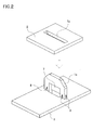
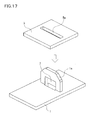
- Fig. 2 is a perspective view of a panel 1 and a panel attaching portion 5 of a speaker bracket 3
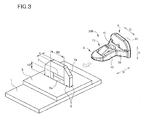
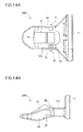
- Fig. 3 is a perspective view of the clip 200
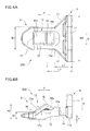
- Fig. 4A is a plain view of the clip 200
- Fig. 4B is a front view of the same.
- the clip 200 for fixing the in-vehicle speaker 100 to an instrument panel (hereinafter simple referred to as a "panel") of a vehicle will be described.
- the speaker 100 will first be described. As depicted in Fig. 1 , the speaker 100 is formed by fixing a speaker body 2 to a speaker bracket 3.
- the speaker bracket 3 is made of a thin metal plate and includes a circular speaker supporting portion 4 supporting the speaker body 2, and a pair of panel attaching portions 5 projected from the speaker supporting portion 4 in the radial direction of the speaker body 2.
- the panel 1 is provided with protrusions 1a located in sections corresponding to a pair of the panel attaching portions 5 in a section on which the speaker 100 is disposed.
- a pair of the panel attaching portions 5 is provided with protrusion insertion holes 5a for inserting the protrusions 1a of the panel 1.
- the speaker 100 is positioned and attached to a predetermined position of the panel 1 by fitting the protrusion insertion holes 5a of the speaker bracket 3 to the corresponding protrusions 1a of the panel 1.
- the protrusion 1a of the panel 1 has a trapezoidal shape in a front view and is provided with a rectangular clip insertion hole 7 facing an upper surface of the panel 1 for inserting a leading end (a locking portion 6) of the clip 200.
- Contact ribs 8 abutting on an inner wall surface of the protrusion insertion hole 5a are disposed at a junction between the protrusion 1a and the upper surface of the panel 1 (a lower end of the protrusion 1a) so as to prevent the protrusion 1a fitted into the protrusion insertion hole 5a from rattling in the protrusion insertion hole 5a (described later).
- the clip 200 of this embodiment is made of a resin material (e.g., polyacetal) and includes an operation portion 9 for operation by the operator and a locking portion 6 inserted and locked into the clip insertion hole 7 of the protrusion 1a of the panel 1 overlapped with the panel attaching portion 5.
- An operational wall 11 is disposed in a standing manner at a rear end of the clip 200 on which an operator places a finger when thrusting the clip 200 into the clip insertion hole 7. The operator pushes and operates the operation portion 9 of the clip 200 with a finger S (see Fig. 6 ). Therefore, a size (width) of the operational wall 11 is slightly larger than the fingertip S of an operator.
- a side of the clip 200 first inserted into the clip insertion hole 7 is defined as a "front side” and a direction of the insertion is described as a "longitudinal direction P".
- a direction orthogonal to the longitudinal direction P in the same plane is described as a “width direction Q”
- a direction orthogonal to the longitudinal direction P and the width direction Q is described as a "height direction R”.
- the locking portion 6 of the clip 200 is disposed to be connected to the operation portion 9 of the clip 200.
- the locking portion 6 includes a locking main body portion 12 extended from a section slightly above a bottom surface 11a of the operational wall 11 to the front side of the operational wall 11 in a direction intersecting with (in this embodiment, substantially orthogonal to) the operational wall 11, and a hook portion 13 disposed at substantially the center of the locking main body portion 12 in plan view.
- the locking main body portion 12 is extended obliquely downward as it goes forward and a bottom surface 12a is curved.
- a front view of the clip 200 see Fig.
- a front side surface of the operational wall 11 is substantially orthogonally connected to an upper surface 12b of the locking main body portion 12.
- the bottom surface 12a of the locking main body portion 12 is positioned lower by a distance e than the bottom surface 11a of the operational wall 11.
- the front end of the locking main body portion 12 has a taper shape in the width direction Q and the height direction R so as to facilitate the insertion into the clip insertion hole 7.
- a width W1 of the locking main body portion 12 is slightly narrower than an inner width W2 of the clip insertion hole 7 in the protrusion 1a of the panel 1, and a width W3 of the operational wall 11 is wider than the inner width W2 of the clip insertion hole 7 (W1 ⁇ W2 ⁇ W3). Therefore, a connecting portion 14 between the operational wall 11 and the locking main body portion 12 is inclined (in a taper shape) in plan view.
- the hook portion 13 of the locking portion 6 is cut out by a cutout portion 15 having an approximate U-shape in plan view and is coupled to the locking main body portion 12 only by a base end 16 disposed on the front side.
- a free end (an end on the rear side) of the hook portion 13 has an approximately triangular cross section and a thickness of the base end 16 (an end on the front side) of the hook portion 13 (a thickness in the height direction R) is thinner than a thickness of the locking main body portion 12. Therefore, the hook portion 13 is elastically freely rotatable using the base end 16 as a fulcrum in a direction of an arrow 17.
- an apex section (a top portion 18) of the free end projects upward from the upper surface of the locking main body portion 12.
- a front section from the top portion 18 of the hook portion 13 is provided with a front side inclined surface 19a leading to the base end 16, and a rear section from the top portion 18 is provided with a rear side inclined surface 19b facing a rear end surface 15a of the cutout portion 15.
- a height H1 from the bottom surface 12a of the locking main body portion 12 to the base end 16 of the hook portion 13 is lower than an inside height H2 of the clip insertion hole 7 in the protrusion 1a of the panel 1 (an inside height while the panel 1 and the panel attaching portion 5 overlap with each other), and a height H3 to the top portion 18 of the hook portion 13 is slightly higher than the inside height H2 of the clip insertion hole 7 (H1 ⁇ H2 ⁇ H3).
- a length L1 from a back surface of the operational wall 11 to the front end of the connecting portion 14 of the locking main body portion 12 is shorter than a distance L2 from the back surface to the top portion 18 of the hook portion 13 (L1 ⁇ L2). Additionally, a distance from the connecting portion 14 of the locking main body portion 12 to the top portion 18 of the hook portion 13 (L2-L1) is shorter than a thickness t of the protrusion 1a (a length in the longitudinal direction P).
- the speaker bracket 3 with the speaker body 2 fixed to the speaker supporting portion 4 is located at a predetermined position of the panel 1 of a vehicle.
- the protrusions 1a disposed on the panel 1 are fitted into the protrusion insertion holes 5a disposed in a pair of the panel attaching portions 5 projected from the speaker bracket 3.
- the speaker bracket 3 is positioned and attached to the predetermined position of the panel 1.
- the protrusion 1a of the panel 1 fitted into the protrusion insertion hole 5a in the panel attaching portion 5 of the speaker bracket 3 projects from the panel attaching portion 5 of the speaker bracket 3, exposing the clip insertion hole 7 disposed in the protrusion 1a. While the panel 1 is in close contact with the panel attaching portion 5 of the speaker bracket 3, the lower end surface of the clip insertion hole 7 is located lower than the upper surface of the panel attaching portion 5.
- a distance K1 between the lower ends of the contact ribs 8 is slightly larger than a corresponding inner width K2 of the protrusion insertion hole 5a of the panel attaching portion 5 (K1>K2).
- the thickness t of the protrusion 1a is obviously smaller than the inner width K2 of the protrusion insertion hole 5a. Therefore, when the protrusion 1a of the panel 1 is fitted into the protrusion insertion hole 5a of the panel attaching portion 5 and the panel 1 is brought into close contact with the panel attaching portion 5, the contact ribs 8 are pressed and elastically deformed by the inner wall surfaces of the protrusion insertion holes 5a.
- the protrusion 1a of the panel 1 has the contact ribs disposed on the both side surfaces in the width direction Q (see Fig. 2 ) and, therefore, the protrusion 1a is also made unmovable in the width direction Q.
- the locking portion 6 (locking main body portion 12) of the clip 200 is inserted into the clip insertion hole 7 of the panel 1.
- the clip 200 is inserted while sliding on the upper surface.
- the width W1 and the height H1 of a section of the locking portion 6 of the clip 200 first inserted are smaller than the inner width W2 and the inside height H2 of the clip insertion hole 7.
- the upper end (the leading end) of the locking main body portion 12 is chamfered at the both ends in the width direction Q and the height direction R. Therefore, an operator can easily insert the locking main body portion 12 of the clip 200 into the clip insertion hole 7. Since the bottom surface 12a of the locking main body portion 12 is lower by the distance e than the bottom surface 11a of the operational wall 11 (see Fig. 4B ), the clip 200 is inserted in a slightly tilted manner as a whole.
- the clip 200 of this embodiment is inserted into the clip insertion hole 7 in an entirely tilted manner.
- the clip 200 is located with the bottom surface 12a of the locking main body portion 12 pressed by the upper surface of the panel attaching portion 5 to compress the locking main body portion 12. Due to this compression force, the panel 1 and the panel attaching portion 5 of the speaker bracket 3 are more rigidly attached to each other. A pressing force of the hook portion 13 of the clip 200 is increased in the height direction R at the same time.
- the front side inclined surface 19a of the hook portion 13 abuts on a horizontal opening edge (a rear side horizontal edge 21a) on the entry side on a ceiling surface of the clip insertion hole 7.
- the hook portion 13 rotates (elastically deforms) downward (in the direction of an arrow 17a) using the base end 16 as a fulcrum.
- the bottom surface 12a of the locking main body portion 12 of the clip 200 drops into the protrusion insertion hole 5a of the panel attaching portion 5.
- the hook portion 13 of the clip 200 When the clip 200 is further thrusted in, the hook portion 13 of the clip 200 further rotates (elastically deforms) downward (in the direction of the arrow 17a).
- the bottom surface 12a of the locking main body portion 12 of the clip 200 correspondingly runs on the upper surface of the panel attaching portion 5.
- the hook portion 13 rotates (elastically deforms) upward (in the direction of an arrow 17b) using the base end 16 as a fulcrum, and the rear side inclined surface 19b of the hook portion 13 abuts on a horizontal opening edge (a front side horizontal edge 21b) on the exit side on the ceiling surface of the clip insertion hole 7, pressing the front side horizontal edge 21b with an elastic restoring force.
- the upper surface 12b of the locking portion 12 upwardly presses the ceiling surface of the clip insertion hole 7 of the protrusion 1a from the inside.
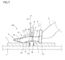
- the bottom surface 12a of the locking main body portion 12 and the bottom surface 11a of the operational wall 11 of the clip 200 press the upper surface of the panel attaching portion 5. Since a difference in height (the distance e) exists between the bottom surface 12a of the locking main body portion 12 and the bottom surface 11a of the operational wall 11 of the clip, the upper surface 12b of the locking main body portion 12 of the clip 200 in this state is located in an obliquely tilted manner relative to the horizontal plane (obliquely such that the height is greater in the front portion and reduced toward the rear side).
- the upper surface 12b of the locking main body portion 12 of the clip 200 presses the clip insertion hole 7 of the protrusion 1a in an oblique manner relative to the vertical direction (the direction orthogonal to an insertion direction K (see Fig. 7 ) of the clip 200). Due to this pressing force F, the protrusion 1a is tilted and bent (elastically deformed) backward by an angle ⁇ . The upper surface 12b of the locking main body portion 12 of the clip 200 is also bent (elastically deformed) due to a reaction force from the protrusion 1a (an elastic restoring force of the protrusion 1a).
- a bent state (imaginary state) of the locking main body portion 12 of the clip 200 is indicated by a dashed-two dotted line in Fig. 7 . Since the hook portion 13 presses the front side horizontal edge 21b of the clip insertion hole 7 and the upper surface 12b of the locking main body portion 12 of the clip 200 is in surface contact with an inner surface of the clip insertion hole 7 of the protrusion 1a in the pressed state to elastically deform the protrusion 1a, an elastic restoring force acts on the protrusion 1a. This elastic restoring force rigidly presses the locking main body portion 12 of the clip 200 and, therefore, the inserted clip 200 is hardly displaced.
- a tilt angle ⁇ of the protrusion 1a is determined depending on a degree of the difference in height (distance e) in the clip 200. In other words, if the difference in height is greater, the upper surface 12b of the inserted clip 200 is more tilted.
- the connecting portions 14 of the locking portion 6 abut on vertical opening edges (vertical edges 22) on the entry side of the both side wall surfaces of the clip insertion hole 7.
- a length L3 of the rear side inclined surface 19b of the hook portion 13 of the clip 200 is set such that, when the both connecting portions 14 abut on the vertical edges 22 of the side wall surfaces of the protrusion 1a, the rear side inclined surface 19b of the hook portion 13 is always located in the rear of the front side horizontal edge 21b of the protrusion 1a.
- the hook portion 13 of the clip 200 presses the front side horizontal edge 21b of the clip insertion hole 7 in the protrusion 1a of the panel 1 and the upper surface 12b of the locking portion 12 presses the clip insertion hole 7 of the protrusion 1a to bend the protrusion 1a. Therefore, the clip 200 is restrained in the height direction R, and the both connecting portions 14 of the clip 200 press the vertical edges 22 in the clip insertion hole 7 to restrain the clip 200 in the width direction Q. Since the protrusion 1a of the panel 1 is pinched by the rear side inclined surface 19a of the hook portion 13 and the both connecting portions 14, the clip 200 is restrained in the longitudinal direction P.
- the speaker bracket 3 is restrained in the longitudinal direction P, the width direction Q, and the height direction R and brought into close contact with the panel 1 by the clip 200.
- the clip 200 is not displaced. This means that the speaker bracket 3 can be attached to the panel 1 without rattling.
- the hook portion 13 is thrusted down in the direction of the arrow 17 (downward) with a tool such as a driver. This releases the pressing (elastic contact) between the rear side inclined surface 19b of the hook portion 13 and the front side horizontal edge 21b of the clip insertion hole 7, allowing the clip 200 to be pulled out from the clip insertion hole 7.
- the applicant compared a speaker fixing operation using a conventional fastening means (bolts and case nuts) with a speaker fixing operation using the clip of this embodiment and acquired the following results.
- the protrusion 1a is described as being bent backward in the longitudinal direction R. However, the protrusion 1a may be bent in the width direction Q.
- a clip 210 of a second embodiment will be described.
- the clip of this embodiment is used for fixing a speaker. Since the clip in a mounted state always receives vibrations from the speaker, it is desirable to more rigidly mount the clip. Therefore, a plurality of stepped portions 23 descending in a step-like shape from the top portion 18 toward the operational wall 11 is disposed on a rear section of the hook portion 13 of the clip 210 of the second embodiment depicted in Fig. 9 (a section corresponding to the rear side inclined surface 19b of the clip 200 of the first embodiment).
- the clip 210 of the second embodiment when the clip 210 of the second embodiment is inserted into the clip insertion hole 7 of the protrusion 1a of the panel 1 and the top portion 18 of the hook portion 13 passes through the front side horizontal edge 21b of the clip insertion hole 7, the front side horizontal edge 21b of the protrusion 1a enters into and engages with any one of the stepped portions 23. Therefore, the clip 210 is restrained in the longitudinal direction P and the height direction R.
- the clip 200 of the first embodiment since a pair of the connecting portions 14 of the clip 210 is in close contact with the vertical edges 22 on the rear side of the protrusion 1a in this state, the clip 210 is restrained in the width direction Q (see Fig. 8A ). As a result, the restraint state between the clip 210 and the protrusion 1a is reinforced and the clip 210 is more certainly prevented from falling off.
- a clip 220 of a third embodiment will be described.
- the clip 220 of the third embodiment depicted in Fig. 11A is provided with a hollow portions 24 penetrating in the height direction R in sections surrounded by the connecting portions 14, the cutout portion 15, and the operational wall 11 in the locking main body portion 12 as compared to the clip 210 of the second embodiment.
- thin-walled portions 25 having a reduced thickness are formed in the connecting portions 14. Therefore, as compared to the clip 200 of the first embodiment, the thin-walled portions 25 (connecting portions 14) are easily elastically deformed.
- the clip 220 of the third embodiment when the clip 220 of the third embodiment is inserted into the clip insertion hole 7 of the protrusion 1a, a pair of the thin-walled portions 25 of the clip 220 comes into close contact with the vertical edges 22 on the rear side.
- the clip 220 is further thrusted in, a pair of the thin-walled portions 25 is pressed and elastically deformed by the vertical edges 22 on the rear side. Therefore, the clip 220 of the third embodiment increases an amount of the elastic deformation of a pair of the thin-walled portions 25 and increases a reaction force so as to increase a restraining force in the width direction Q such that the clip 220 is hardly displaced.
- Fig. 11A an elastically deformed state of a pair of the thin-walled portions 25 is indicated by dashed-two dotted lines.
- connecting sections between a pair of the thin-walled portions 25 and the operational wall 11 may be cutoff in the clip 220 of the third embodiment to form a pair of the thin-walled portions 25 into a cantilever stabilizer shape.
- a pair of the thin-walled portions 25 is more easily elastically deformed.
- a clip 240 of a fifth embodiment will be described.
- the clip 240 of the fifth embodiment is provided with coupling portions 26 obliquely coupling the upper surface of the locking main body portion 12 and the front side surface of the operational wall 11 as compared to the clip 220 of the third embodiment.
- the stepped portions 23 of the clip 240 enters into and engages with the front side horizontal edge 21b and the coupling portions 26 of the clip 240 come into close contact with the rear side horizontal edge 21a.
- the clip 240 of the fifth embodiment is further enforced in the restraint in the longitudinal direction P and the height direction R of the clip 240 by both the stepped portions 23 and the coupling portions 26.
- upper ends of the coupling portions 26 may be cutoff in the clip 240 of the fifth embodiment to form the coupling portions 26 into a cantilever stabilizer shape. As a result, the coupling portions 26 are more easily elastically deformed.
- steps similar to those of the clip 210 of the second embodiment may be formed in the sections of the thin-walled portions 25 and the coupling portions 26.
- the side surfaces and/or the upper surface 12b of the locking main body portion 12 may be provided with hook portions 27, 28 having an approximate isosceles triangular cross section.
- the hook portions 27 press the vertical edges 22 on the front side of the clip insertion hole 7 and the hook portions 28 press the front side horizontal edge 21b of the clip insertion hole 7.
- the clip 260 is more certainly restrained in the longitudinal direction R and the width direction Q.
- the clips 200 to 260 of the embodiments are formed such that a difference (e) in height is generated between the bottom surface 12a of the locking main body portion 12 and the bottom surface 11a of the operational wall 11 to tilt the upper surface 12b of the locking portion 12 in the attached state so as to bend the protrusion 1a.
- the protrusion 1a of the panel 1 may be bent by disposing on the front portion of the panel attaching portion 5 an inclined surface 29 gradually increasing in height toward the front side as depicted in Fig. 16A or by disposing a convex portion 31 on the front portion of the panel attaching portion 5 as depicted in Fig. 16B .
- the protrusion insertion holes 5a of the speaker bracket 3 of the embodiments have an approximate rectangular shape corresponding to the cross-sectional shape of the protrusion 1a, the shape may be a circular or triangular shape depending on the cross-sectional shape of the protrusion 1a.
- the embodiments have been described in terms of fastening two members (the panel 1 and the panel attaching portion 5 of the speaker bracket 3).
- the number of fastened members may be three or more.
- the embodiments have the contact ribs 8 disposed on the sections of the protrusion 1a of the panel 1.
- the contact ribs 8 abut on inner peripheral surfaces of the protrusion insertion holes 5a to prevent the panel attaching portion 5 from rattling.
- the contact ribs 8 may not be disposed on the protrusion 1a of the panel 1 on the condition that the panel attaching portion 5 does not rattle.
- the clip according to the invention is usable for fixing a vibrating member (e.g., in-vehicle speaker).
Landscapes
- Engineering & Computer Science (AREA)
- General Engineering & Computer Science (AREA)
- Mechanical Engineering (AREA)
- Connection Of Plates (AREA)
- Snaps, Bayonet Connections, Set Pins, And Snap Rings (AREA)
- Fittings On The Vehicle Exterior For Carrying Loads, And Devices For Holding Or Mounting Articles (AREA)
- Clamps And Clips (AREA)
- Insertion Pins And Rivets (AREA)
Applications Claiming Priority (2)
| Application Number | Priority Date | Filing Date | Title |
|---|---|---|---|
| JP2009271455 | 2009-11-30 | ||
| PCT/JP2010/066780 WO2011065121A1 (ja) | 2009-11-30 | 2010-09-28 | クリップ |
Publications (1)
| Publication Number | Publication Date |
|---|---|
| EP2508765A1 true EP2508765A1 (de) | 2012-10-10 |
Family
ID=44066225
Family Applications (1)
| Application Number | Title | Priority Date | Filing Date |
|---|---|---|---|
| EP10832968A Withdrawn EP2508765A1 (de) | 2009-11-30 | 2010-09-28 | Klemme |
Country Status (5)
| Country | Link |
|---|---|
| US (1) | US8943655B2 (de) |
| EP (1) | EP2508765A1 (de) |
| JP (1) | JP5620922B2 (de) |
| CN (1) | CN102656375B (de) |
| WO (1) | WO2011065121A1 (de) |
Cited By (4)
| Publication number | Priority date | Publication date | Assignee | Title |
|---|---|---|---|---|
| FR3014508A1 (fr) * | 2013-12-06 | 2015-06-12 | Peugeot Citroen Automobiles Sa | Dispositif de fixation securisee d'une piece sur une tole de carrosserie de vehicule automobile, laquelle piece peut etre un bloc d'eclairage de plaque d'immatriculation arriere. |
| WO2017178104A1 (de) * | 2016-04-13 | 2017-10-19 | A.RAYMOND et Cie. SCS | Clip zum befestigen eines ersten elements an einem zweiten element |
| RU2695835C2 (ru) * | 2015-02-18 | 2019-07-29 | ФОРД ГЛОУБАЛ ТЕКНОЛОДЖИЗ, ЭлЭлСи | Крепежное устройство для прикрепления первой детали ко второй детали и чехол направляющей сиденья |
| GB2634308A (en) * | 2023-10-06 | 2025-04-09 | Jaguar Land Rover Ltd | Retention assembly |
Families Citing this family (36)
| Publication number | Priority date | Publication date | Assignee | Title |
|---|---|---|---|---|
| US9121426B2 (en) * | 2010-11-09 | 2015-09-01 | Illinois Tool Works Inc. | Bracket clip |
| JP5730129B2 (ja) * | 2011-05-27 | 2015-06-03 | 本田技研工業株式会社 | カウル締結構造 |
| JP5764522B2 (ja) * | 2012-04-26 | 2015-08-19 | 本田技研工業株式会社 | クリップ |
| JP5927021B2 (ja) * | 2012-04-26 | 2016-05-25 | 株式会社ニフコ | クリップ |
| JP5864391B2 (ja) | 2012-09-28 | 2016-02-17 | 株式会社ニフコ | クリップ |
| JP5864392B2 (ja) * | 2012-09-28 | 2016-02-17 | 本田技研工業株式会社 | 車両部品の連結構造 |
| JP5863728B2 (ja) * | 2013-08-09 | 2016-02-17 | 本田技研工業株式会社 | 部材の締結構造 |
| US10188179B2 (en) * | 2013-10-11 | 2019-01-29 | Aplix | Fastener |
| US9474338B2 (en) * | 2013-10-11 | 2016-10-25 | Aplix | Fastener |
| JP6111217B2 (ja) * | 2014-04-02 | 2017-04-05 | 豊田鉄工株式会社 | 重ね合わせ複合部品 |
| JP6277910B2 (ja) * | 2014-08-22 | 2018-02-14 | トヨタ自動車株式会社 | 車両用組み付け構造及び車両用組み付け部の製造方法 |
| JP6414737B2 (ja) * | 2014-09-11 | 2018-10-31 | スズキ株式会社 | ガーニッシュ取付構造 |
| JP6374347B2 (ja) * | 2015-05-15 | 2018-08-15 | 株式会社ニフコ | クリップ |
| US10865819B2 (en) * | 2016-05-20 | 2020-12-15 | Yazaki North America, Inc. | Tuneless cantilever system |
| CN107571813A (zh) * | 2016-07-05 | 2018-01-12 | 福特环球技术公司 | 用于车辆的连接组件、线束夹组件及内饰组件 |
| US10328870B2 (en) * | 2016-07-25 | 2019-06-25 | Deere & Company | Work vehicle upholstery mounting system |
| JP6669623B2 (ja) * | 2016-09-23 | 2020-03-18 | 株式会社ニフコ | 部材取付構造及び取付クリップ |
| US10513164B2 (en) * | 2017-02-09 | 2019-12-24 | Denso International America, Inc. | HVAC case fastener |
| JP6872436B2 (ja) * | 2017-06-26 | 2021-05-19 | 株式会社デンソーテン | 車載機器の取付構造及び取付方法 |
| US10464501B2 (en) * | 2017-09-21 | 2019-11-05 | GM Global Technology Operations LLC | Fastener for attaching a trim component to an inner structure of a vehicle |
| CN207961202U (zh) * | 2018-01-08 | 2018-10-12 | 福特环球技术公司 | 子零件和零件组件 |
| JP7042147B2 (ja) * | 2018-04-09 | 2022-03-25 | 大和化成工業株式会社 | センターコンソールの組み付け構造及びセンターコンソールの組み付け方法 |
| CN111287033B (zh) * | 2018-12-10 | 2024-08-23 | 洛阳双瑞橡塑科技有限公司 | 一种内锁式减振扣件系统 |
| US11454263B2 (en) * | 2019-01-07 | 2022-09-27 | Illinois Tool Works Inc. | Systems and methods for a connector |
| CN110025168A (zh) * | 2019-05-16 | 2019-07-19 | 深圳快品信息技术有限公司 | 一种采用后装式主控单元的餐饮自提柜 |
| EP3742004B1 (de) * | 2019-05-22 | 2023-05-10 | DENSO THERMAL SYSTEMS S.p.A. | Verbindungsvorrichtung zum verbinden zweier bauteile aus kunststoff |
| US10857954B1 (en) * | 2019-07-29 | 2020-12-08 | Toyota Motor Engineering & Manufacturing North America, Inc. | Clip assemblies |
| JP7471120B2 (ja) * | 2020-03-23 | 2024-04-19 | 株式会社ファルテック | 係合構造 |
| KR102343026B1 (ko) * | 2020-04-09 | 2021-12-23 | (주)엘엑스하우시스 | 차량용 가니쉬 결합구조체 |
| JP7556705B2 (ja) * | 2020-06-18 | 2024-09-26 | トヨタ自動車九州株式会社 | キックセンサの構造及びその取付け構造 |
| US11772577B2 (en) * | 2020-10-06 | 2023-10-03 | GM Global Technology Operations LLC | Serviceable shoe-clip fastener for vehicle trim attachment |
| CN112283216A (zh) * | 2020-10-28 | 2021-01-29 | 浙江佳乐科仪股份有限公司 | 一种快速锁紧装置 |
| US20240182290A1 (en) * | 2021-03-23 | 2024-06-06 | Ts Tech Co., Ltd. | Interior component for conveyance |
| JP7590312B2 (ja) * | 2021-12-06 | 2024-11-26 | 株式会社ニフコ | 機器取付構造 |
| JP7280992B1 (ja) | 2022-03-22 | 2023-05-24 | 三恵技研工業株式会社 | クリップ設置構造 |
| JP2023140209A (ja) * | 2022-03-22 | 2023-10-04 | 三恵技研工業株式会社 | ホールシール材の取付構造 |
Family Cites Families (12)
| Publication number | Priority date | Publication date | Assignee | Title |
|---|---|---|---|---|
| JPS6023545Y2 (ja) * | 1981-03-26 | 1985-07-13 | トヨタ自動車株式会社 | スナツプ式固着具 |
| JPH089312B2 (ja) | 1985-08-26 | 1996-01-31 | 加藤発条株式会社 | 外装部品の取付構造 |
| JPS6256809U (de) * | 1985-09-30 | 1987-04-08 | ||
| JPH0353041Y2 (de) * | 1987-08-31 | 1991-11-19 | ||
| JP2593839Y2 (ja) * | 1993-06-16 | 1999-04-19 | フオスター電機株式会社 | 車載ドア用スピーカの取付構造 |
| DE69615118T2 (de) * | 1995-09-19 | 2002-06-27 | Daiwa Kasei Kogyo K.K., Okazaki | Schenkel zur Befestigung eines Komponentes |
| AU3433200A (en) * | 2000-03-24 | 2001-10-03 | Grupo Antolin-Ingenieria, S.A. | Metal-plastic staple for fixing vehicle roofs and accessories to the body of a vehicle |
| JP3723054B2 (ja) | 2000-07-14 | 2005-12-07 | 日東工業株式会社 | パネル固定用クリップ |
| JP2002372011A (ja) | 2001-06-12 | 2002-12-26 | Mitsui Miike Mach Co Ltd | くさびを用いた板材の固定具 |
| JP4472456B2 (ja) * | 2004-08-05 | 2010-06-02 | 株式会社ニフコ | 留め具 |
| US7337505B1 (en) * | 2007-03-13 | 2008-03-04 | Illinois Tool Works Inc | Panel fastener |
| US9121426B2 (en) * | 2010-11-09 | 2015-09-01 | Illinois Tool Works Inc. | Bracket clip |
-
2010
- 2010-09-28 CN CN201080053830.0A patent/CN102656375B/zh active Active
- 2010-09-28 JP JP2011543155A patent/JP5620922B2/ja active Active
- 2010-09-28 WO PCT/JP2010/066780 patent/WO2011065121A1/ja not_active Ceased
- 2010-09-28 US US13/511,200 patent/US8943655B2/en active Active
- 2010-09-28 EP EP10832968A patent/EP2508765A1/de not_active Withdrawn
Non-Patent Citations (1)
| Title |
|---|
| See references of WO2011065121A1 * |
Cited By (7)
| Publication number | Priority date | Publication date | Assignee | Title |
|---|---|---|---|---|
| FR3014508A1 (fr) * | 2013-12-06 | 2015-06-12 | Peugeot Citroen Automobiles Sa | Dispositif de fixation securisee d'une piece sur une tole de carrosserie de vehicule automobile, laquelle piece peut etre un bloc d'eclairage de plaque d'immatriculation arriere. |
| RU2695835C2 (ru) * | 2015-02-18 | 2019-07-29 | ФОРД ГЛОУБАЛ ТЕКНОЛОДЖИЗ, ЭлЭлСи | Крепежное устройство для прикрепления первой детали ко второй детали и чехол направляющей сиденья |
| WO2017178104A1 (de) * | 2016-04-13 | 2017-10-19 | A.RAYMOND et Cie. SCS | Clip zum befestigen eines ersten elements an einem zweiten element |
| EP3859169A1 (de) * | 2016-04-13 | 2021-08-04 | A. Raymond et Cie. SCS | Clip zum befestigen eines ersten elements an einem zweiten element |
| US11384779B2 (en) | 2016-04-13 | 2022-07-12 | A. Raymond Et Cie | Clip for fastening a first element to a second element |
| US11885360B2 (en) | 2016-04-13 | 2024-01-30 | A. Raymond Et Cie | Clip for fastening a first element to a second element |
| GB2634308A (en) * | 2023-10-06 | 2025-04-09 | Jaguar Land Rover Ltd | Retention assembly |
Also Published As
| Publication number | Publication date |
|---|---|
| CN102656375A (zh) | 2012-09-05 |
| CN102656375B (zh) | 2014-06-25 |
| US8943655B2 (en) | 2015-02-03 |
| WO2011065121A1 (ja) | 2011-06-03 |
| US20120227219A1 (en) | 2012-09-13 |
| JP5620922B2 (ja) | 2014-11-05 |
| JPWO2011065121A1 (ja) | 2013-04-11 |
Similar Documents
| Publication | Publication Date | Title |
|---|---|---|
| US8943655B2 (en) | Clip | |
| US10946808B2 (en) | Display screen mounting assembly | |
| US7120971B2 (en) | Low insertion effort u-base retainer | |
| JP4190409B2 (ja) | クリップ | |
| EP2090475B1 (de) | In zwei Stufen arbeitende Halterung mit großem Rückhaltevermögen | |
| JP2005308221A (ja) | 多段組み立て補助ファスナ | |
| JP4997274B2 (ja) | ライセンスプレート取付構造 | |
| EP2749778A1 (de) | Klemme | |
| GB2464243A (en) | Fixation device, structure for fixing member, method for fixing member, and method of releasing fixation effected by fixation device | |
| EP2757274A1 (de) | Verschluss | |
| CN102667286B (zh) | 夹具 | |
| CN1937340B (zh) | 线夹子 | |
| CN101811480A (zh) | 用于内饰部件的衬垫材料固定结构 | |
| US20240183369A1 (en) | Vehicle module clip | |
| US20250163949A1 (en) | Fastening Clip Assembly | |
| US20070099452A1 (en) | Apparatus of attaching part | |
| US20070044990A1 (en) | Automotive cable holding system | |
| JP5088120B2 (ja) | 電気接続箱 | |
| JP2003056532A (ja) | クランプ | |
| EP1484513A1 (de) | Elastisches Befestigungselement mit einer Verdrehsicherung | |
| CN116803719A (zh) | 遮阳板安装装置 | |
| WO2023226589A1 (zh) | 安装部件 | |
| JP2007181363A (ja) | 取付具 | |
| KR20240079393A (ko) | 자동차용 모듈 클립 | |
| CN121363577A (zh) | 可拆卸紧固夹 |
Legal Events
| Date | Code | Title | Description |
|---|---|---|---|
| PUAI | Public reference made under article 153(3) epc to a published international application that has entered the european phase |
Free format text: ORIGINAL CODE: 0009012 |
|
| 17P | Request for examination filed |
Effective date: 20120529 |
|
| AK | Designated contracting states |
Kind code of ref document: A1 Designated state(s): AL AT BE BG CH CY CZ DE DK EE ES FI FR GB GR HR HU IE IS IT LI LT LU LV MC MK MT NL NO PL PT RO SE SI SK SM TR |
|
| DAX | Request for extension of the european patent (deleted) | ||
| STAA | Information on the status of an ep patent application or granted ep patent |
Free format text: STATUS: THE APPLICATION HAS BEEN WITHDRAWN |
|
| 18W | Application withdrawn |
Effective date: 20150727 |