EP2510842A2 - Combined smoothie maker and juicer - Google Patents
Combined smoothie maker and juicer Download PDFInfo
- Publication number
- EP2510842A2 EP2510842A2 EP11825414A EP11825414A EP2510842A2 EP 2510842 A2 EP2510842 A2 EP 2510842A2 EP 11825414 A EP11825414 A EP 11825414A EP 11825414 A EP11825414 A EP 11825414A EP 2510842 A2 EP2510842 A2 EP 2510842A2
- Authority
- EP
- European Patent Office
- Prior art keywords
- residue
- net drum
- juice
- discharge hole
- housing
- Prior art date
- Legal status (The legal status is an assumption and is not a legal conclusion. Google has not performed a legal analysis and makes no representation as to the accuracy of the status listed.)
- Granted
Links
Images







Classifications
-
- A—HUMAN NECESSITIES
- A47—FURNITURE; DOMESTIC ARTICLES OR APPLIANCES; COFFEE MILLS; SPICE MILLS; SUCTION CLEANERS IN GENERAL
- A47J—KITCHEN EQUIPMENT; COFFEE MILLS; SPICE MILLS; APPARATUS FOR MAKING BEVERAGES
- A47J43/00—Implements for preparing or holding food, not provided for in other groups of this subclass
- A47J43/04—Machines for domestic use not covered elsewhere, e.g. for grinding, mixing, stirring, kneading, emulsifying, whipping or beating foodstuffs, e.g. power-driven
- A47J43/042—Mechanically-driven liquid shakers
-
- A—HUMAN NECESSITIES
- A47—FURNITURE; DOMESTIC ARTICLES OR APPLIANCES; COFFEE MILLS; SPICE MILLS; SUCTION CLEANERS IN GENERAL
- A47J—KITCHEN EQUIPMENT; COFFEE MILLS; SPICE MILLS; APPARATUS FOR MAKING BEVERAGES
- A47J19/00—Household machines for straining foodstuffs; Household implements for mashing or straining foodstuffs
- A47J19/02—Citrus fruit squeezers; Other fruit juice extracting devices
- A47J19/025—Citrus fruit squeezers; Other fruit juice extracting devices including a pressing screw
-
- A—HUMAN NECESSITIES
- A47—FURNITURE; DOMESTIC ARTICLES OR APPLIANCES; COFFEE MILLS; SPICE MILLS; SUCTION CLEANERS IN GENERAL
- A47J—KITCHEN EQUIPMENT; COFFEE MILLS; SPICE MILLS; APPARATUS FOR MAKING BEVERAGES
- A47J19/00—Household machines for straining foodstuffs; Household implements for mashing or straining foodstuffs
- A47J19/02—Citrus fruit squeezers; Other fruit juice extracting devices
- A47J19/027—Centrifugal extractors
-
- A—HUMAN NECESSITIES
- A47—FURNITURE; DOMESTIC ARTICLES OR APPLIANCES; COFFEE MILLS; SPICE MILLS; SUCTION CLEANERS IN GENERAL
- A47J—KITCHEN EQUIPMENT; COFFEE MILLS; SPICE MILLS; APPARATUS FOR MAKING BEVERAGES
- A47J43/00—Implements for preparing or holding food, not provided for in other groups of this subclass
- A47J43/04—Machines for domestic use not covered elsewhere, e.g. for grinding, mixing, stirring, kneading, emulsifying, whipping or beating foodstuffs, e.g. power-driven
- A47J43/046—Machines for domestic use not covered elsewhere, e.g. for grinding, mixing, stirring, kneading, emulsifying, whipping or beating foodstuffs, e.g. power-driven with tools driven from the bottom side
Definitions
- the present invention relates, in general, to juicers having a smoothie making function and, more particularly, to a juicer which can make green vegetable juice, fruit juice or soybean milk from vegetables, fruits or soybeans, and can easily make smoothies without leaving behind residue, such as fiber, in the smoothies even when whole vegetables or whole fruits are put into the juicer without having been cut.
- An existing juicer is an appliance that makes juice using centrifugal separation after a raw material is put into a feed tube, by pressing and crushing the material at high speed.
- a juicer is problematic in that the characteristic taste and nutrients of a fruit may be destroyed during the high-speed crushing process, it is difficult to make green vegetable juice from vegetables having stems and leaves, it is difficult to make juice from fruits that are highly viscous, such as kiwis or strawberries, and in addition it is almost impossible to make soybean milk from soybeans. Further, if a user continues to make juice, the juicer must be frequently disassembled and washed to remove residue from the mesh.
- a food processing apparatus which is similar to a juicer of the present invention essentially requires cleanliness and smooth washing or cleaning. If food remains behind in the apparatus or if the apparatus becomes dirty, the food will spoil easily and bacteria will breed. Hence, internal components of the apparatus need to be easy to disassemble and clean.
- Korean U.M. Registration No. 190676 was filed by the inventor of this invention and pertains to a juice extractor having a grinding function.
- the juice extractor is configured so that a long feed screw is horizontally assembled with a drum, together with an extracting net and a drum cap, to be coupled to a sidewall of a driving unit.
- the overall length thereof is long, and the extractor performs a juice extracting operation when a raw material is being slowly fed horizontally after being put into a feed tube.
- the juice extractor has drawbacks in that a wide space is required when the extractor is being used or is in storage, and in that the extracting speed is slow because a raw material is extracted while moving horizontally, and thick highly viscous juice does not flow down well, but may collect in the drum. Further, the juice extractor is problematic in that the feed screw has no rotating shaft on an end thereof, so that the end of the feed screw without the rotating shaft may shake and collide with a blade on an inner wall of the extracting net while rotating, thus causing noise and abrasion.
- juice extractor must be disassembled and washed after being used, to overcome a hygienic problem caused by the remaining food.
- the juice extractor requires a configuration that minimizes inconvenience during disassembly and assembly.
- the juice extractor is in need of further improvement to achieve durability during the use of the extractor.
- Korean Patent No. 793852 has been proposed, which deals with a juice extractor. This was filed by the inventor of this invention after which it was registered.
- the juice extractor can make soybean milk from soybeans using the principle of a millstone which grinds, presses and crushes the beans, and can make fruit juice from fruits having high viscosity, such as tomato, kiwis or strawberries, by rubbing, pressing and crushing the fruits over a grater. Since a housing of the juice extractor is vertically coupled to an upper portion of a driving unit, a wide space is not required to use or store the extractor in. Further, since the position of a juice outlet is at a more upper position compared to the prior art, it is possible to utilize various kinds of cups.
- the juice extractor is advantageous in that the housing is vertically coupled to the upper portion of the driving unit, so that a raw material can naturally move downwards both by gravity and by the rotation of a feed screw, and the extracting speed is fast and juice does not stagnate, so that juice can be quickly extracted from any kind of vegetable or fruit.
- Another advantage of the juice extractor disclosed in Korean Patent No. 793852 resides in that it has a simple construction and can be easily assembled and disassembled, so that it is easy to clean the interior of the extractor.
- the juice extractor disclosed in Korean Patent No. 793852 is advantageous in that it can be easily washed.
- the juice extractor must be disassembled, washed and assembled in order to solve a hygienic problem which may be caused by food left behind in the juice extractor or when making different kinds of juices in succession. Therefore, it is required to provide a juice extractor having an improved structure which can allow a user to more easily wash the juice extractor.
- Korean Patent No. 755440 which was filed by the inventor of this invention and then was registered, proposes a juice extractor with a structure that is an improvement over that of the juice extractor disclosed in Korean Patent No. 793852 .
- this juice extractor is provided with a brush for continuously brushing both the outer surface of the net drum and the inner surface of the housing.
- this juice extractor is problematic in that, when the juice extractor is operated while water is being put into the housing through the feed tube, the brush is rotated and washes the lower portions of both the housing and the net drum; however, in the above state, the water does not reach the upper portions, but is discharged to the outside of the housing through the juice outlet, so that the upper portions may not be washed. This is a problem in need of a solution.
- tough fiber included in the residue is cut by the rotation of the feed screw 200 at the location between a feed screw 200 and a net drum bottom ring 340 and is discharged to a residue outlet 570 through a net drum discharge hole 360 formed in the lower end of the net drum bottom ring 340.
- residue outlet 570 a net drum discharge hole 360 formed in the lower end of the net drum bottom ring 340.
- uncut tough fiber residue may be left behind between the feed screw 200 and the net drum bottom ring 340.
- the uncut tough fiber residue may slightly push the feed screw 200 upwards and form a space between a discharge step 225 formed in the lower surface of the feed screw 200 and the net drum bottom ring 340 having the net drum discharge hole 360, Therefore, the uncut tough fiber residue gradually collects in the space and the residue having the uncut tough fiber gradually closes the net drum discharge hole 360, so that the residue may not be smoothly discharged through the hole and this disturbs the continuous juice extraction, thereby bringing the juice extraction process to a halt. Thus, an improvement that solves this problem is required.
- the present invention has been made keeping in mind the above problems occurring in the related art, and the present invention is intended to propose a juicer having a smoothie making function, which can make soft mixed smoothies by cutting, crushing and squeezing vegetables having lots of fiber or whole fruits in such a way that inedible residue, such as fiber, is isolated in a net drum and an edible material of the vegetables or fruits is continuously circulated between the interior and exterior of a net drum until the edible material becomes a part of the soft mixed smoothies, and which can efficiently discharge the residue through a net drum discharge hole and, further, can frequently discharge the residue from the net drum when necessary, thereby repeatedly making smoothies, and, further, can be operated to wash the interior elements thereof with water charged in the housing, thereby allowing the elements to be efficiently washed without having to disassemble the juicer.
- a smoothie making function which can make soft mixed smoothies by cutting, crushing and squeezing vegetables having lots of fiber or whole fruits in such a way that inedible residue, such as fiber, is isolated in a
- a juicer having a smoothie making function including: a lid having a feed tube for putting food into the juicer; a feed screw for feeding the input food downwards while cutting, crushing and squeezing the food, with a rotating shaft being vertically provided in the feed screw; a housing assembled to a lower end of the lid, with a juice outlet and a residue outlet being formed on an outer surface of the housing in such a way that the juice outlet and the residue outlet are spaced apart from each other, the feed screw being rotatably placed in the housing and a housing discharge hole being formed in a bottom of the housing such that the housing discharge hole communicates with the residue outlet; a net drum surrounding the feed screw and having an entirely or partially meshed sidewall, with a net drum discharge hole being formed in the net drum and communicating with the residue outlet; a motor unit provided with a seat on an upper end thereof for seating the housing thereon, with a drive shaft provided in a center of the seat and
- the net drum discharge hole may be formed in a lower surface of the net drum
- the juicer may further include: a residue packing mounted to a lower portion of the net drum and opening or closing the net drum discharge hole or the residue outlet.
- the net drum discharge hole may be formed in a lower surface of the net drum, and the juicer may further include: a residue control unit for opening or closing the net drum discharge hole or the residue outlet.
- the net drum discharge hole may be formed on a lower portion of a sidewall of the net drum, and the juicer may further include: a residue control unit for opening or closing the net drum discharge hole or the residue outlet.
- the juicer may further include: a discharge guide surface which is bent downwards, the discharge guide surface being mounted to a predetermined lower portion of an outer surface of the net drum at a location around the net drum discharge hole and forming a channel for communicating the net drum discharge hole with the housing discharge hole.
- the residue outlet may be provided with an adjustment hole at a location adjacent to the net drum discharge hole
- the residue control unit may include: a control lever rotatably mounted to a lower surface of the housing; and a rotary panel extending from the control lever and inserted in the adjustment hole so as to open or close the net drum discharge hole or the residue outlet.
- the net drum discharge hole may be provided with a residue packing, the residue packing being configured to be elastically deformed and opening or closing the net drum discharge hole, and the rotary panel may come into close contact with a lower surface of the residue packing, thereby controlling elastic deformation of the residue packing.
- the juicer may further include: a brush installed between the housing and the net drum and rotated in conjunction with the feed screw and brushing an inner surface of the housing or an outer surface of the net drum.
- the juicer may further include: a brush installed between the housing and the net drum and rotated in conjunction with an intermediate gear rotated by a secondary shaft connected to the motor unit.
- the juice control unit may include: a rotary unit rotatably connected to the juice outlet; and a closure unit provided in an end of the rotary unit and configured to close an end of the juice outlet.
- Fig. 1A is an exploded perspective view illustrating a juicer having a smoothie making function according to a first embodiment of the present invention.
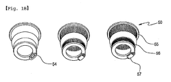
- Fig. 1B is a perspective view illustrating a plurality of net drums according to different modifications of the present invention.
- Fig. 1C is a sectional view illustrating the operation of the juicer shown in Fig. 1A .
- the juicer 1 having the smoothie making function according to the present invention includes a lid 10, a feed screw 40, a housing 20, a net drum 50, a motor unit 30 and a juice control unit 70. Further, the juicer 1 having the smoothie making function according to the present invention may include a brush 60. Further, when a residue outlet 22 is formed in the housing 20, a residue control unit 80 may be provided in the juicer 1.
- the juicer 1 having the smoothie making function according to the present invention is configured such that it may be used as a juicer, which can extract juice from fruits and can discharge juice and residue separately, and may be used as a smoothie maker.
- the smoothie maker is a device for making smoothies which are produced by mixing frozen fruits or frozen vegetables with milk, soybean milk, etc.
- the lid 10 is a part through which a raw material, such as vegetables, fruits, etc., is put into the juicer 1 having the smoothie making function of the present invention.
- the lid 10 is provided with a feed tube 13 and forms an upper part of the juicer 1 having the smoothie making function according to the present invention.
- the lid 10 is, configured such that a predetermined amount of raw material can be continuously put into the juicer. Therefore, the structure of the lid 10 is not completely isolated from the outside, but the top of the lid 10 is partially open as shown in Fig. 1A .
- the housing 20 is closely assembled with the lower end of the lid 10.
- the housing 20 has a bowl shape and functions to collect juice and discharge the juice to the outside of the juicer.
- the housing 20 is provided with both a juice outlet 21 and a residue outlet 22 on the outer surface thereof, so that the juice outlet 21 discharges juice and the residue outlet 22 discharges residue from which the juice has been strained.
- Fig. 1A the housing 20 having the residue outlet 22 is illustrated.
- the residue outlet 22 may not be formed in the housing 20.
- the residue from which juice has been strained in the housing 20 will be collected on the bottom of the net drum 50.
- the residue may be removed from the net drum 50 after the feed screw 40 is removed from the net drum 50.
- the residue outlet 22 be provided in the juicer 1 having the smoothie making function. Therefore, it should be understood that the juicer described in the following description is a type provided with the residue outlet 22 if there is no specific expression.
- the juice control unit 70 is configured to open or close the juice outlet 21. Further, the residue control unit 80 is provided in a residue discharge path. The residue control unit 80 is configured to open or close a net drum discharge hole 54 and to open or close the residue outlet 22 formed in the housing 20. Both the juice control unit 70 and the residue control unit 80 will be described in detail later herein.
- the net drum 50 functions to divide the juice outlet 21 from the residue outlet 22.
- the space defined outside the net drum 50 communicates with the juice outlet 21 and the space defining the interior of the net drum 50 communicates with the residue outlet 22.
- both the feed screw 40 and the net drum 50 are operated along with a screw pump, so that juice is discharged from the net drum 50 to the juice outlet 21 and residue remains in the net drum 50.
- the residue is then discharged from the net drum 50 to the outside sequentially through the net drum discharge hole 54 and the residue outlet 22.
- a waterproof cylinder 23 may be provided in the housing 20 in such a manner that it protrudes upwards from the central area of the bottom of the housing 20, with a through hole 23a formed through the center of the waterproof cylinder 23.
- the lower end of a rotating shaft 41 is inserted downwards through the through hole 23a and is connected to a drive shaft 32.
- the waterproof cylinder 23 protrudes upwards from the bottom of the housing 20, so that it is possible to prevent juice from flowing into a motor unit 30 through the through hole 23a.
- a through-hole packing 25 made of rubber or silicone is formed in the through hole 23a, thus more efficiently preventing the juice from flowing into the motor unit 30.
- a juice discharge channel 27 may be formed in the bottom of the housing 20 at a location right adjacent to the edge of the waterproof cylinder 23.
- the juice discharge channel 27 is depressed downwards so that the lower end of the feed screw 40 is rotatably inserted into the juice discharge channel 27.
- a circular guide step 28 may be formed between the juice discharge channel 27 and a wall of the housing 20 in such a way as to protrude upwards.
- the lower end of the net drum 50 is seated on the bottom surface inside the guide step 28.
- the guide step 28 and the edge of the lower end of the net drum 50 are formed to conform to each other.
- the bottom surface of the housing 20 is divided into inner and outer spaces by the guide step 28.
- the feed screw 40 and the net drum 50 are positioned in the inner space, while most of the juice is collected in the outer space prior to being discharged.
- the juice outlet 21 is formed on the edge of the lower end of the housing 20 and discharges the juice. Preferably, the juice outlet 21 is inclined slightly downwards to prevent the juice from collecting.
- a housing discharge hole 29 is formed downwards through the bottom surface of the housing 20 such that the housing discharge hole 29 is defined inside the guide step 28.
- the residue outlet 22 is connected to the housing discharge hole 29, so that the residue remaining after the juice is strained is discharged through the residue outlet 22. That is, the residue outlet 22 extends from the housing discharge hole 29 to outside the housing 20.
- the net drum discharge hole 54 is formed in the lower end of the net drum 50 such that the hole 54 is aligned with the housing discharge hole 29.
- the separated residue passes sequentially through the net drum discharge hole 54 and the housing discharge hole 29 prior to being discharged via the residue outlet 22.
- a residue packing 57 made of rubber or silicone may be interposed in the net drum discharge hole 54 in such a way that the packing 57 can close the net drum discharge hole 54.
- the residue packing 57 is configured such that, when no external force is applied to the residue packing 57, the packing 57 can close the net drum discharge hole 54 and, in contrast, when an external force is applied to the residue packing 57 (especially, pressure is applied from an upper portion to a lower portion), the residue packing 57 can be elastically deformed and opens the net drum discharge hole 54.
- a seat 31 is formed on the top of the motor unit 30, and the drive shaft 32 is provided on a central portion of the seat 31.
- the motor unit 30 is a part that generates power in the juicer 1 and has a motor and a reduction gear therein.
- the lower end of the housing 20 is placed tightly on the seat 31.
- the drive shaft 32 is formed on the central portion of the seat 31, and is connected to the motor and the reduction gear in the motor unit 30.
- the drive shaft 32 is rotated at low speed by the motor and the reduction gear, thus rotating the feed screw 40.
- the feed screw 40 is provided with the rotating shaft 41, with a screw body 48 and screw blades 42 provided around the rotating shaft 41.
- the upper end of the rotating shaft 41 is supported by the lid 10, while the lower end thereof is connected to the drive shaft 32.
- a shaft hole is formed in a central portion of a back of the lid so that the upper end of the rotating shaft 41 can be inserted into the shaft hole so as to be supported thereby.
- the lower end of the rotating shaft 41 is connected to the drive shaft 32, and the feed screw 40 can be rotated by the rotation of the drive shaft 32.
- the rotating shaft 41 rotates integrally with the drive shaft 32 without slipping after it is coupled to the drive shaft 32.
- the drive shaft 32 has the shape of a prism. A recess may be formed in the lower end of the rotating shaft 41 in such a way that the drive shaft 32 can be precisely inserted into the rotating shaft 41.
- the screw blades 42 are helically formed around the rotating shaft 41.
- the entire screw body 48 is thick so as to press and squeeze input food using the junction between the screw blades 42.
- the screw body 48 is shaped in such a way that its diameter is small at an upper portion thereof and gradually increases in a direction from the upper portion to the lower portion. Therefore, the upper portion of the screw body 48 is slightly spaced apart from the net drum 50, while the lower portion thereof is close to the net drum 50.
- a lower space 43 is formed in the lower portion of the feed screw 40 in such a way that the area of the lower end of the feed screw 40 around the rotating shaft 41 is depressed upwards.
- An inner ring 44 is formed on the lower portion of the feed screw 40 such that the inner ring 44 can surround the lower space 43, and an outer ring 45 is further formed outside the inner ring 44.
- a circular protrusion insert channel 46 is formed between the inner ring 44 and the outer ring 45.
- a screw gear 47 protrudes downwards from the inner ring 44, is formed to fit the juice discharge channel 27, and is rotatably inserted into the juice discharge channel 27.
- An intermediate gear g is rotatably provided on the bottom of the housing 20, and engages with the screw gear 47. When the feed screw 40 rotates, the intermediate gear g engaging with the screw gear 47 rotates.
- the intermediate gear g serves as a medium for rotating the brush 60 as will be described later herein.
- the brush 60 may be rotated in conjunction with an intermediate gear g that is installed between the housing and the net drum and is rotated by a secondary shaft (not shown) connected to the motor unit.
- the brush 60 is rotated in conjunction with the intermediate gear g rotated by the secondary shaft, so that it is possible to appropriately control the rotating speed of the brush according to the kinds of vegetables or fruits separately from the rotating speed of the drive shaft.
- the net drum 50 surrounds the feed screw 40, and may have various shapes.
- Fig. 1B shows various embodiments of the net drum 50.
- the net drum may have a closed sidewall or a meshed sidewall having a plurality of meshes.
- the juicer of the present invention may be used to realize the original function of separating juice through the meshed sidewall of the net drum 50. Meanwhile, when the sidewall of the net drum 50 is closed, the juicer may be used to crush a material, such as garlic. Therefore, the juicer of this invention can be utilized for various purposes. That is, the latter case may be used in a case where it is unnecessary to separate juice from residue and squeezing or crushing is required.
- the net drum 50 has an upper net 55 in an upper portion thereof, and a lower net 56 in a lower portion thereof.
- a plurality of meshes is formed in the upper net 55 and the lower net 56. Relatively large meshes are formed in the upper net 55, while small meshes are compactly formed in the lower net 56.
- a central portion of a bottom of the net drum 50 is open to define an inner-ring insert hole (reference numeral is omitted).
- the inner ring 44 provided in the lower portion of the feed screw 40 is inserted into the inner-ring insert hole, and the screw gear 47 is inserted into the juice discharge channel 27.
- a circular protrusion 52 is formed around the inner-ring insert hole to protrude upwards.
- the circular protrusion 52 is inserted into the circular protrusion insert hole 46.
- the outer ring 45 of the feed screw 40 is inserted into a circular groove 53 of the net drum 50.
- both the feed screw 40 and the net drum 50 can be operated along with the screw pump and a predetermined space which is hermetically sealed in the bottom is defined between the outer surface of the feed screw 40 and the inner surface of the net drum 50.
- the circular groove 53 is formed in the bottom of the net drum 50 at a location outside the circular protrusion 52.
- the net drum discharge hole 54 is formed downwards through a predetermined portion of the bottom of the net drum 50.
- the net drum discharge hole 54 protrudes slightly downwards from the lower end of the net drum 50, and is inserted into the housing discharge hole 29.
- the brush 60 is installed between the housing 20 and the net drum 50 and brushes the inner surface of the housing 20 and the outer surface of the net drum 50.
- the brush 60 includes a brush holder 61, a brush gear 62 formed on the lower end of the brush holder 61, and a meshed brush 63 coupled to a side of the brush holder 61.
- the brush holder 61 is spaced apart both from the housing 20 and from the net drum 50 without being in close contact with them.
- the brush gear 62 engages with the intermediate gear g, so that the brush gear 62 rotates when the feed screw 40 rotates.
- the meshed brush 63 is mounted to the brush holder 61 so that its outer end is in contact with the inner surface of the housing 20 and its inner end is in contact with the outer surface of the net drum 50. Therefore, when the brush 60 rotates, the meshed brush 63 sweeps both the inner surface of the housing 20 and the outer surface of the net drum 50, so that the juice can smoothly flow down.
- the juicer When the juicer is used as a juicer for extracting juice, the juice and residue can be easily discharged by the operation of the brush 60.
- the brush 60 increases the movability of circulating smoothies, thus allowing the smoothies to easily circulate.
- an outstanding effect of the brush 60 is its use as a washing means. That is, juice or residue may be caught in or adhere to the net drum 50 and the housing 20. In this case, when the brush 60 rotates with washing water, the residue may be easily removed. Thus, the brush 60 serves as a washing brush.
- the juicer having the smoothie making function according to the present invention is basically configured to separately discharge juice and residue.
- the process of making smoothies using the juicer will be described hereinbelow.
- the process of making smoothies using the juicer of the present invention is performed in a state in which the juice control unit 70 and the residue control unit 80 close the juice outlet 21 and the residue outlet 22, respectively.
- a predetermined amount of milk or soybean milk and frozen vegetables or fruits are put into the feed tube 13, and then the juicer is operated.
- the vegetables or fruits are thus moved downwards while being squeezed and crushed by the feed screw 40 and, in the above state, crushed fine pieces and juice are discharged from the lower net 56 to the outside of the net drum 50.
- the feed screw 40 and the net drum 50 are operated along with the screw pump, and the vegetables or fruits are continuously squeezed by the rotating feed screw 40 and the crushed fine pieces and juice are continuously discharged from the lower net 56, so that the smoothies are moved from the lower to the upper portion of the housing 20.
- the smoothies are introduced from the upper portion of the housing 20 into the net drum 50 through the upper net 55 and are repeatedly processed by the feed screw 40.
- the juicer 1 having the smoothie making function according to the present invention when used to make juice having no residue, the juice making process is performed in a state in which the residue outlet 22 is closed by the residue control unit 80. Therefore, the residue is not directly discharged, but is repeatedly crushed and squeezed, so that it is possible to prevent fruit juice from remaining in the residue. Further, the juice extraction rate of the juicer can be maximized by controlling the residue control unit 80.
- the feed screw 40 having the rotating shaft 41 is rotated by the drive shaft 32 in a state in which the feed screw 40 is placed in the net drum 50 having the entirely or partially meshed sidewall. Therefore, the feed screw 40 moves input food downwards while cutting, crushing and squeezing the food, thereby producing fine pieces and juice.
- the fine pieces and juice which are produced by the operation of both the feed screw 40 and the net drum 50 operated in conjunction with the screw pump, are continuously fed to the space defined between the inner surface of the housing 20 and the outer surface of the net drum 50 through the lower net 56 of the net drum 50 and are moved downwards.
- the fine pieces and juice are moved upwards from the lower portion in the space defined between the inner surface of the housing 20 and the outer surface of the net drum 50. In the upper portion of the space, the fine pieces and juice are fed into the net drum 50 through the upper net 55. Therefore, in the housing 20, the fine pieces and juice can continuously circulate between the inside and outside of the net drum 50 through the upper and lower nets, so that the juicer can make homogenized mixed juice and the residue can be continuously filtered by the lower net 56 of the net drum, thereby reliably separating the juice from the residue. Further, the residue can be discharged from the housing when necessary. Therefore, the juicer of the present invention can efficiently make smoothies by mixing vegetables or fruits with milk or ice cream. Particularly, the juicer can make soft smoothies having no residue.
- Fig. 2A is a sectional view illustrating a juicer having a smoothie making function according to another embodiment of the present invention.
- Fig. 2B is a sectional view of the juicer 1 having the smoothie making function shown in Fig. 2A , with both the juice control unit 70 and the residue control unit 80 being opened.
- the residue control unit 80 is a unit for opening or closing the residue outlet 22.
- the residue control unit 80 may be variously embodied if the unit can open or close the residue outlet without affecting the functioning of this invention.
- the residue control unit 80 includes a sliding body 81, a sliding lever 82 and a sliding panel 83, so that the residue control unit 80 can easily and efficiently open or close the residue outlet 22.
- the sliding body 81 is mounted to the residue outlet 22 in such a way that the sliding body 81 can slide on the residue outlet 22.
- a slit may be formed in the residue outlet 22 and the sliding body 81 may be installed in the slit such that the sliding body 81 can slide along with the slit, as shown in Fig. 2A .
- the sliding lever 82 is integrated with the sliding body 81 into a single structure and protrudes outside the residue outlet 22, so that a user can easily control the movement of the sliding body 81 by moving the sliding lever 82 with a hand.
- the sliding panel 83 is integrated with the sliding body 81 into a single structure and is movable in the residue outlet 22.
- the residue outlet 22 may be provided therein with a guide groove (not shown) for guiding movement of the sliding panel 83.
- the sliding panel 83 has a basic function of closing the residue outlet 22. However, the sliding panel 83 may be configured to support the residue packing 57.
- the residue outlet 22 can be closed only by the residue control unit 80.
- the juicer 1 having the smoothie making function according to the present invention may be constructed without the residue packing 57.
- the residue control unit 80 including the sliding panel 83 may be configured in such a way that the residue control unit 80 does not completely close the residue outlet 22 because the residue packing 57 can prevent discharge of the residue.
- the sliding panel 83 is configured to support the residue packing 57 in the state where the sliding panel 83 is in close contact with the lower surface of the residue packing 57.
- the sliding panel 83 can support the residue packing 57 without leaving any gap between the net drum discharge hole 54 and the residue packing 57.
- Fig. 3 is a bottom view of the housing 20 shown in Fig. 1A .
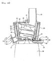
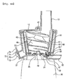
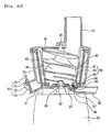
- Figs. 4A through 4D are sectional views illustrating the used state of the juicer 1 having the smoothie making function shown in Fig. 1A . Described in detail, Fig. 4A illustrates a state in which the residue control unit 80 completely supports the lower surface of the residue packing 57 such that the residue packing 57 is not deformed.
- Fig. 4B illustrates a state in which the residue control unit 80 is partially opened and supports a part of the lower surface of the residue packing 57.
- Fig. 4C illustrates a state in which the residue control unit 80 does not support the residue packing 57.
- Fig. 4D illustrates a state in which only the residue control unit 80 is operated without the residue packing 57.
- Fig. 3 illustrates the operation of the residue control unit 80 according to the first embodiment of the present invention which is different from the embodiment shown in Figs. 2A and 2B .
- the residue outlet 22 is shown in a sectioned state, with the juice control unit 70 not being illustrated.
- the residue control unit 80 functions to open or close the residue path. Described in detail, the residue control unit 80 functions to open or close the net drum discharge hole 54 or the housing discharge hole 29.
- the residue control unit 80 may be variously embodied if the unit 80 can open or close the residue path without affecting the functioning of this invention.
- the residue control unit 80 may be configured to open or close the net drum discharge hole 54 in a state in which the unit 80 is in close contact with the lower end of the net drum discharge hole 54.
- the residue control unit 80 may be configured to open or close the housing discharge hole 29 or the residue outlet 22.
- the residue control unit 80 may be configured in such a way that it can support the residue packing 57 and thereby can close the net drum discharge hole 54 without being put in close contact with the lower end of the net drum discharge hole 54.
- the residue control unit 80 includes a control lever 84 and a rotary panel 85 which can open or close the net drum discharge hole 54 in response to a rotating motion of the control lever 84.
- the rotary panel 85 is inserted into the residue outlet 22 and opens or closes the lower end of the net drum discharge hole 54, with an adjustment hole 24 being formed at a predetermined position in the residue outlet 22.
- the size of the adjustment hole 24 is sufficient as long as it permits a slidable insertion of the rotary panel 85. That is, the size of the adjustment hole 24 is equal to or greater than the sectional area of the rotary panel 85.
- the adjustment hole 24 is preferably formed on the rear end of the residue outlet 22.
- the rotary lever 84 is mounted to the bottom of the housing 20 in such a way as to rotate around a rotating shaft 86.
- the end of the rotary lever 84 protrudes further from the sidewall of the housing 20, thus allowing a user to easily grasp and manipulate it. While the rotary panel 85 is repeatedly inserted into or pulled out of the residue outlet 22 through the adjustment hole 24 by the manipulation of the rotary lever 84, the net drum discharge hole 54 or the housing discharge hole 29 is closed or opened.
- the basic function of the rotary panel 85 is to close the residue path.
- the rotary panel 85 may be configured to support the residue packing 57.
- the net drum discharge hole 54 can be closed only by the residue control unit 80.
- the juicer 1 having the smoothie making function according to the present invention may be constructed without the residue packing 57.
- the residue control unit 80 including the rotary panel 85 may be configured in such a way that the residue control unit 80 does not completely close the net drum discharge hole 54 because the residue packing 57 can prevent the residue from being discharged.
- the rotary panel 85 is configured to support the residue packing 57 in a state in which the rotary panel 85 comes into close contact with the lower surface of the residue packing 57.
- the rotary panel 85 can support the residue packing 57 without there being any gap between the net drum discharge hole 54 and the residue packing 57.
- the residue control unit 80 is provided on the residue outlet 22 such that the unit 80 opens or closes the residue path.
- the residue control unit 80 is selectively used depending on whether it is necessary to continuously discharge juice and residue, whether it is necessary to make smoothies or whether it is necessary to wash the juicer.
- the residue control unit 80 controls a support degree while supporting the lower surface of the residue packing 57, thus reliably closing the residue outlet 22 and continuously discharging a proper amount of residue depending on requirements.
- residue packing 57 The case having the residue packing 57 will be described. First, one end of the residue packing 57 is mounted to an end of the net drum discharge hole 54 while the other end of the packing 57 is configured in the form of a free end. Further, the residue packing 57 may be configured such that the packing 57 comes into close contact with the lower end of the net drum discharge hole 54 or with the inner surface of the hole 54.
- the end of the residue packing 57 at which the packing 57 is mounted to the net drum discharge hole 54 will be referred to as the rear end thereof and the free end of the residue packing 57 will be referred to as the front end thereof.
- the residue packing 57 allows the residue to be discharged in the case where the residue is pressed by the feed screw 40, and maintains a sealed state in the case where a substance other than the residue, for example, water is not pressed by the feed screw 40.
- the residue packing 57 prevents the residue containing some juice from being discharged out. That is, the residue packing 57 sufficiently presses the residue to completely separate juice from the residue, and thereafter discharges the residue.
- the rotary panel 85 moves from the rear end to the front end of the residue packing 57.
- the degree to which the lower surface of the residue packing 57 is supported varies depending on the degree of movement. That is, the degree to which the rotary panel 85 supports the residue packing 57 may be controlled by adjusting the rotary lever 84.
- the rotary panel 85 does not support the residue packing 57 or slightly supports the residue packing 57.
- the rotary panel 85 may be adjusted to sufficiently support the residue packing 57, so that a compressive force suitable for extracting juice may be provided depending on the type of input material.
- the movement of the discharged residue is primarily suppressed by the residue packing 57, and is secondarily suppressed by the residue control unit 80, thus preventing insufficiently compressed residue from being discharged (in a state in which juice is not sufficiently extracted from the residue).
- the residue control unit 80 may be opened or closed by simple manipulation. When the residue control unit 80 is closed, the residue path is closed and prevented from opening. Moreover, the residue control unit 80 supports the lower surface of the residue packing 57, and efficiently prevents the residue outlet 22 from being opened in cooperation with the residue packing 57, thus realizing an excellent sealing effect.
- the juice control unit 70 functions to open or close the juice outlet 21 and may be configured in the form of a service water valve or a valve of a hot and chilled water generator.
- the juice control unit 70 is appropriately constructed to realize the easy control of the juice outlet 21 and to realize the easy washing and cleaning of the juicer used as a smoothie maker which is a food processing apparatus.
- the juice control unit 70 will be described in detail.
- the juice control unit 70 includes a rotary unit 71 rotatably connected to the juice outlet 21, and a closure unit 72 provided at a side of the rotary unit 71 and functioning to open or close the end of the juice outlet 21.
- the rotary unit 71 is a part, at which the juice control unit 70 is connected to the juice outlet 21, and is configured such that the juice control unit 70 can be rotated in the juice outlet 21 by the rotary unit 71.
- the rotary unit 71 may be constructed in the form of a typical hinge device so that the rotary unit 71 can be rotated around a shaft. The rotary unit 71 will be described in detail later herein.
- the closure unit 72 is a part which selectively prevents juice from being discharged through the juice outlet 21.
- the closure unit 72 is provided with a closure packing 73 in an end thereof.
- the closure unit 72 be integrated with the rotary unit 71 into a single structure.
- the closure unit 72 is configured such that the closure packing 73 can be mounted thereto.
- the closure packing 73 is made of an elastic material, such as rubber or silicone, and is mounted to the end of the closure unit 72. Further, the closure packing 73 is configured such that it can close the juice outlet 21 and can come into close contact with the inner or outer surface of the juice outlet 21.
- the closure packing 73 shown in Fig. 2A is a type in which the packing 73 comes into close contact with the inner surface of the juice outlet 21.
- the closure packing 73 may be configured in the form of a cap having a diameter larger than that of the end of the juice outlet 21, so that the closure packing 73 can come into close contact with the outer circumferential surface of the juice outlet 21 while surrounding the end of the juice outlet 21.
- the packing 73 when the closure packing 73 is configured to come into close contact with the inner circumferential surface of the juice outlet 21, it is preferred that the packing 73 have an outer diameter slightly larger than the inner diameter of the juice outlet 21. On the contrary, when the closure packing 73 is configured to come into close contact with the outer circumferential surface of the juice outlet 21, it is preferred that the packing 73 have an inner diameter slightly smaller than the outer diameter of the juice outlet 21. Therefore, when the closure packing 73 is fitted into or over the juice outlet 21, the packing 73 is elastically deformed and reliably closes the juice outlet 21.
- a lever 74 is provided at a location opposed to the closure unit 72 based on the rotary unit 71 and functions to rotate the closure unit 72.
- the lever 74 is configured to allow a user to hold it and may be provided with an uneven surface for preventing the hand from slipping off.
- the rotary unit 71 may be mounted to the upper, lower, left-side or right-side portion of the juice outlet 21. However, to realize the easy opening or closing of the closure unit 72, it is preferred that the rotary unit 71 be mounted to the upper portion of the juice outlet 21, as described above.
- the rotary unit 71 and the closure unit 72 can be rotated on the juice outlet 21 in an integrated state, so that the juice control unit 70 can be easily manipulated without the juice control unit 70 being lost.
- the lever 74 in addition to the rotary unit 71 and the closure unit 72 is provided in the juice control unit 70, thus making it easier to manipulate the juice control unit 70.
- Figs. 5A through 5E illustrate a juicer having a smoothie making function according to a further embodiment of the present invention, in which a net drum discharge hole 54 for discharging residue from a net drum 50 is formed in the sidewall 555 of the lower portion of the net drum 50 in such a way that the net drum discharge hole 54 communicates with a residue outlet 22, with a residue control unit 80 provided in the juicer and opening or closing the net drum discharge hole 54 or the residue outlet 22.
- a circular protrusion insert channel 46 is formed around an inner ring 44 and receives therein a circular protrusion 52 of the net drum 50, with an outer ring 45 formed around the circular protrusion insert channel 46.
- a screw discharge step 425 is formed on the lower end of each lower screw blade.
- the screw discharge step 425 functions to discharge the residue that has moved to the lower end of the net drum 50 to outside of the net drum 50 through the net drum discharge hole 54 formed in the net drum sidewall 555.
- the screw discharge step 425 be rapidly inclined downwards from the lower end of the screw blade. Because the screw discharge step 425 is rapidly inclined downwards from the lower end of the lower screw blade, the screw discharge step 425 can efficiently push the residue to the net drum discharge hole 54 with increased force.
- a bottom ring 340 defining the inner-ring insert hole 557 therein is formed in such a way that the inner ring 44 of the feed screw 40 can be inserted into the inner-ring insert hole 557.
- the bottom ring 340 forms the bottom surface of the net drum 50.
- the net drum discharge hole 54 is formed in the lower portion of the net drum sidewall 555 and communicates with the residue outlet 22.
- a discharge guide surface 556 that is bent downwards is mounted to a predetermined lower portion of the outer surface of the net drum 50.
- the discharge guide surface 556 forms a channel, through which the net drum discharge hole 54 communicates with a housing discharge hole 29 formed in the bottom of a housing 20.
- a plurality of screw-bottom discharge steps 475 are formed by protruding from the lower surface of the feed screw 40 in such a way that each of the steps 475 extends from the inside to the outside and the outer ends of the steps 475 continuously form the rear ends thereof based on the rotating direction of the feed screw 40.
- a plurality of net drum bottom-ring discharge steps 535 are formed by protruding from the bottom surface of the circular groove 53 formed in the net drum bottom ring 340 in such a way that each of the steps 535 extends from the inside to the outside and the outer ends of the steps 535 continuously form front ends thereof based on the rotating direction of the feed screw 40.
- the net drum discharge hole 54 is formed in the lower portion of the sidewall 555 of the net drum 50 and the screw discharge steps 425 are formed on the lower portions of the side surfaces of the respective screw blades, so that the residue can be discharged through the net drum discharge hole 54 formed in the sidewall of the net drum 50. Because the net drum discharge hole 54 is formed in the lower portion of the net drum 50, the gap formed between the net drum discharge hole 54 and the screw discharge steps 425 may be gradually enlarged by the accumulated fiber during a process of extracting juice from vegetables or fruits having lots of tough fiber, and, occasionally, the feed screw 40 may be pushed upwards and, accordingly, the operation of the feed screw 40 may be suddenly stopped.
- a plurality of screw-bottom discharge steps 475 are formed by protruding from the lower surface of the feed screw 40 in such a way that each of the steps 475 extends from the inside to the outside and the outer ends of the steps 475 continuously form the rear ends thereof based on the rotating direction of the feed screw 40.
- a plurality of net drum bottom-ring discharge steps 535 are formed by protruding from the bottom surface of the circular groove 53 formed in the net drum bottom ring 340 in such a way that each of the steps 535 extends from the inside to the outside and the outer ends of the steps 535 continuously form front ends thereof based on the rotating direction of the feed screw 40.
- the feed screw having the rotating shaft is rotated by the drive shaft in a state in which the feed screw is placed in the net drum having the entirely or partially meshed sidewall. Therefore, the feed screw moves the input food downwards while cutting, crushing and squeezing the food, thereby producing fine pieces and juice.
- the fine pieces and juice which are produced by the operation of both the feed screw and the net drum operated in conjunction with the screw pump, are continuously fed to the space defined between the inner surface of the housing and the outer surface of the net drum through the lower net of the net drum and move downwards.
- the fine pieces and juice move upwards from the lower portion in the space defined between the inner surface of the housing and the outer surface of the net drum. In the upper portion of the space, the fine pieces and juice are fed into the net drum through the upper net. Therefore, in the housing, the fine pieces and juice can continuously circulate between the inside and outside of the net drum through the upper and lower nets, so that the juicer can make a uniformly mixed juice and the residue can be continuously filtered by the lower net of the net drum, thereby reliably separating the juice from the residue. Further, the residue can be discharged from the housing when necessary. Therefore, the juicer of the present invention can efficiently make smoothies by mixing vegetables or fruits with milk or soybean milk. Particularly, the juicer can make soft smoothies having no residue.
- the residue packing is mounted to the power end of the net drum, so that, when the net drum is separated from the housing, the residue packing is removed along with the net drum from the housing, thereby being easily washed and cleaned.
- the residue control unit for opening or closing the residue discharge path is provided, so that the residue control unit can be selectively used according to the case in which it is necessary to continuously discharge juice and residue and to the case in which it is necessary to make smoothies, and to the case in which it is necessary to wash the juicer having the smoothie making function.
- the net drum discharge hole is formed in the lower portion of the net drum sidewall and the discharge steps are formed on the side surfaces of the screw blades of the feed screw, so that the residue can be discharged through the sidewall of the net drum. Therefore, unlike the embodiment in which the net drum discharge hole is formed in the lower end of the net drum and, accordingly, the gap defined between the net drum discharge hole and the screw discharge steps is enlarged by the accumulated fiber residue during a process of extracting juice from vegetables or fruits having lots of tough fiber, the present invention is advantageous in that, even when a material having lots of tough fiber is put into the juicer and the feed screw is slightly pushed upwards by the material, tough fiber residue can be easily discharged through the net drum discharge hole without accumulating therein.
- the discharge guide surface that is bent downwards is mounted to the predetermined lower portion of the outer surface of the net drum.
- This discharge guide surface forms a channel, through which the net drum discharge hole communicates with the housing discharge hole formed in the bottom of the housing. Due to the net drum discharge guide surface, the residue can be easily discharged through the housing discharge hole.
- the juicer having the smoothie making function according to the present invention is provided with the control lever for controlling the opening ratio of the residue outlet, so that the juice extraction rate can be controlled by manipulating the control lever.
- the residue packing for opening or closing the residue discharge path is provided on the lower surface of the net drum, thereby easily opening or closing the residue outlet. Further, the lower surface of the residue packing can be closely supported by the residue control unit, so that the opening ratio of the residue packing can be controlled and, accordingly, it is possible to reliably seal the residue outlet or to continuously discharge an appropriate amount of residue through the residue outlet.
- the brush promotes the circulation of smoothies between the interior and exterior of the net drum. Further, when it is required to wash the juicer, water can be fully charged in the net drum by closing the juice outlet, so that the interior elements of the juicer having the smoothie making function can be easily and simply washed by rotating both the feed screw and the brush in the juicer without disassembling the juicer.
- the brush is rotated in conjunction with the intermediate gear that is rotated by the secondary shaft, so that the rotating speed of the brush can be controlled separately from the rotating speed of the drive shaft so that it appropriately suits the kinds of vegetable or fruit.
- the juicer having the smoothie making function is provided with the juice control unit including the rotary unit and the closure unit which are integrated with each other into a single structure, so that the juice control unit can be rotated in an integrated state on the juice outlet and, accordingly, it is easy to manipulate the juice control unit without losing the elements of the juice control unit.
Landscapes
- Engineering & Computer Science (AREA)
- Food Science & Technology (AREA)
- Mechanical Engineering (AREA)
- Apparatuses For Bulk Treatment Of Fruits And Vegetables And Apparatuses For Preparing Feeds (AREA)
- Food-Manufacturing Devices (AREA)
- Paper (AREA)
Abstract
Description
- The present invention relates, in general, to juicers having a smoothie making function and, more particularly, to a juicer which can make green vegetable juice, fruit juice or soybean milk from vegetables, fruits or soybeans, and can easily make smoothies without leaving behind residue, such as fiber, in the smoothies even when whole vegetables or whole fruits are put into the juicer without having been cut.
- An existing juicer is an appliance that makes juice using centrifugal separation after a raw material is put into a feed tube, by pressing and crushing the material at high speed. However, such a juicer is problematic in that the characteristic taste and nutrients of a fruit may be destroyed during the high-speed crushing process, it is difficult to make green vegetable juice from vegetables having stems and leaves, it is difficult to make juice from fruits that are highly viscous, such as kiwis or strawberries, and in addition it is almost impossible to make soybean milk from soybeans. Further, if a user continues to make juice, the juicer must be frequently disassembled and washed to remove residue from the mesh.
- A food processing apparatus which is similar to a juicer of the present invention essentially requires cleanliness and smooth washing or cleaning. If food remains behind in the apparatus or if the apparatus becomes dirty, the food will spoil easily and bacteria will breed. Hence, internal components of the apparatus need to be easy to disassemble and clean.
- Korean U.M. Registration No.
190676 - Thus, the juice extractor has drawbacks in that a wide space is required when the extractor is being used or is in storage, and in that the extracting speed is slow because a raw material is extracted while moving horizontally, and thick highly viscous juice does not flow down well, but may collect in the drum. Further, the juice extractor is problematic in that the feed screw has no rotating shaft on an end thereof, so that the end of the feed screw without the rotating shaft may shake and collide with a blade on an inner wall of the extracting net while rotating, thus causing noise and abrasion.
- Further, such a juice extractor must be disassembled and washed after being used, to overcome a hygienic problem caused by the remaining food. Thus, the juice extractor requires a configuration that minimizes inconvenience during disassembly and assembly. Further, the juice extractor is in need of further improvement to achieve durability during the use of the extractor.
- In order to solve the problems, Korean Patent No.
793852 - Further, the juice extractor is advantageous in that the housing is vertically coupled to the upper portion of the driving unit, so that a raw material can naturally move downwards both by gravity and by the rotation of a feed screw, and the extracting speed is fast and juice does not stagnate, so that juice can be quickly extracted from any kind of vegetable or fruit.
- Another advantage of the juice extractor disclosed in Korean Patent No.
793852 - Due to the above-mentioned structural characteristics, the juice extractor disclosed in Korean Patent No.
793852 - In an effort to solve the above-mentioned problems, Korean Patent No.
755440 793852 - Further, in the juice extracting operation of the juice extractor disclosed in Korean Patent No.
755440 Fig. 6 , tough fiber included in the residue is cut by the rotation of thefeed screw 200 at the location between afeed screw 200 and a netdrum bottom ring 340 and is discharged to aresidue outlet 570 through a netdrum discharge hole 360 formed in the lower end of the netdrum bottom ring 340. However, when the residue includes lots of tough fiber, uncut tough fiber residue may be left behind between thefeed screw 200 and the netdrum bottom ring 340. The uncut tough fiber residue may slightly push thefeed screw 200 upwards and form a space between adischarge step 225 formed in the lower surface of thefeed screw 200 and the netdrum bottom ring 340 having the netdrum discharge hole 360, Therefore, the uncut tough fiber residue gradually collects in the space and the residue having the uncut tough fiber gradually closes the netdrum discharge hole 360, so that the residue may not be smoothly discharged through the hole and this disturbs the continuous juice extraction, thereby bringing the juice extraction process to a halt. Thus, an improvement that solves this problem is required. - Further, some users need smoothies made from vegetables and fruits. However, a conventional smoothie maker cannot make smoothies from vegetables having lots of fiber. Additionally, to make smoothies from fruits using the conventional smoothie maker, the rinds and seeds of the fruits must be removed and this is inconvenient to users. Further, effective components of fruits are more abundantly present in the rinds and seeds than in the flesh of fruits and, accordingly, it is not good to make smoothies from fruits after removing the rinds and seeds. Therefore, an apparatus capable of making smoothies from vegetables of rich fiber or from whole fruits is required.
- Accordingly, the present invention has been made keeping in mind the above problems occurring in the related art, and the present invention is intended to propose a juicer having a smoothie making function, which can make soft mixed smoothies by cutting, crushing and squeezing vegetables having lots of fiber or whole fruits in such a way that inedible residue, such as fiber, is isolated in a net drum and an edible material of the vegetables or fruits is continuously circulated between the interior and exterior of a net drum until the edible material becomes a part of the soft mixed smoothies, and which can efficiently discharge the residue through a net drum discharge hole and, further, can frequently discharge the residue from the net drum when necessary, thereby repeatedly making smoothies, and, further, can be operated to wash the interior elements thereof with water charged in the housing, thereby allowing the elements to be efficiently washed without having to disassemble the juicer.
- In order to achieve the above object, according to one aspect of the present invention, there is provided a juicer having a smoothie making function, including: a lid having a feed tube for putting food into the juicer; a feed screw for feeding the input food downwards while cutting, crushing and squeezing the food, with a rotating shaft being vertically provided in the feed screw; a housing assembled to a lower end of the lid, with a juice outlet and a residue outlet being formed on an outer surface of the housing in such a way that the juice outlet and the residue outlet are spaced apart from each other, the feed screw being rotatably placed in the housing and a housing discharge hole being formed in a bottom of the housing such that the housing discharge hole communicates with the residue outlet; a net drum surrounding the feed screw and having an entirely or partially meshed sidewall, with a net drum discharge hole being formed in the net drum and communicating with the residue outlet; a motor unit provided with a seat on an upper end thereof for seating the housing thereon, with a drive shaft provided in a center of the seat and connected to the rotating shaft, thereby rotating the feed screw; and a juice control unit for opening or closing the juice outlet. During an operation of the juicer with the juice outlet being closed, food repeatedly and continuously circulates through the upper and lower nets of the net drum while being cut, crushed or squeezed. However, in such a case, residue including fiber is isolated in the net drum.
- In an embodiment, the net drum discharge hole may be formed in a lower surface of the net drum, and the juicer may further include: a residue packing mounted to a lower portion of the net drum and opening or closing the net drum discharge hole or the residue outlet.
- In an embodiment, the net drum discharge hole may be formed in a lower surface of the net drum, and the juicer may further include: a residue control unit for opening or closing the net drum discharge hole or the residue outlet.
- In another embodiment, the net drum discharge hole may be formed on a lower portion of a sidewall of the net drum, and the juicer may further include: a residue control unit for opening or closing the net drum discharge hole or the residue outlet.
- Here, the juicer may further include: a discharge guide surface which is bent downwards, the discharge guide surface being mounted to a predetermined lower portion of an outer surface of the net drum at a location around the net drum discharge hole and forming a channel for communicating the net drum discharge hole with the housing discharge hole.
- Further, the residue outlet may be provided with an adjustment hole at a location adjacent to the net drum discharge hole, and the residue control unit may include: a control lever rotatably mounted to a lower surface of the housing; and a rotary panel extending from the control lever and inserted in the adjustment hole so as to open or close the net drum discharge hole or the residue outlet.
- Further, the net drum discharge hole may be provided with a residue packing, the residue packing being configured to be elastically deformed and opening or closing the net drum discharge hole, and the rotary panel may come into close contact with a lower surface of the residue packing, thereby controlling elastic deformation of the residue packing.
- The juicer may further include: a brush installed between the housing and the net drum and rotated in conjunction with the feed screw and brushing an inner surface of the housing or an outer surface of the net drum.
- The juicer may further include: a brush installed between the housing and the net drum and rotated in conjunction with an intermediate gear rotated by a secondary shaft connected to the motor unit.
- Further, the juice control unit may include: a rotary unit rotatably connected to the juice outlet; and a closure unit provided in an end of the rotary unit and configured to close an end of the juice outlet.
- The above and other objects, features and other advantages of the present invention will be more clearly understood from the following detailed description when taken in conjunction with the accompanying drawings, in which:
-
Fig. 1A is an exploded perspective view illustrating a juicer having a smoothie making function according to a first embodiment of the present invention; -
Fig. 1B is a perspective view illustrating a plurality of net drums according to different modifications of the present invention; -
Fig. 1C is a sectional view illustrating the operation of the juicer shown inFig. 1A ; -
Fig. 2A is a sectional view illustrating a juicer having the smoothie making function according to a second embodiment of the present invention; -
Fig. 2B is a sectional view illustrating the operation of the juicer ofFig. 2A , in which both a juice control unit and a residue control unit are opened; -
Fig. 3 is a bottom view illustrating a housing used in the juicer ofFig. 1A ; -
Figs. 4A through 4D are sectional views illustrating the operation of the juicer shown inFig. 1A ; -
Fig. 5A is an exploded perspective view illustrating a juicer having a smoothie making function according to a third embodiment of the present invention; -
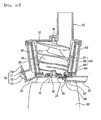
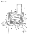
Fig. 5B is a partially sectioned perspective view of a housing used in the juicer ofFig. 5A ; -
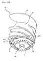
Fig. 5C is a partially sectioned perspective view of a net drum used in the juicer ofFig. 5A ; -
Fig. 5D is a perspective view of a feed screw used in the juicer ofFig. 5A ; -
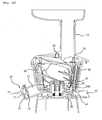
Fig. 5E is a sectional view illustrating the operation of the juicer shown inFig. 5A ; and -
Fig. 6 is an exploded perspective view illustrating a conventional juice extractor. - Reference will now be made in greater detail to a preferred embodiment of the invention with reference to' the accompanying drawings.
-
Fig. 1A is an exploded perspective view illustrating a juicer having a smoothie making function according to a first embodiment of the present invention.Fig. 1B is a perspective view illustrating a plurality of net drums according to different modifications of the present invention.Fig. 1C is a sectional view illustrating the operation of the juicer shown inFig. 1A . - The juicer 1 having the smoothie making function according to the present invention includes a
lid 10, afeed screw 40, ahousing 20, anet drum 50, amotor unit 30 and ajuice control unit 70. Further, the juicer 1 having the smoothie making function according to the present invention may include abrush 60. Further, when aresidue outlet 22 is formed in thehousing 20, aresidue control unit 80 may be provided in the juicer 1. - As will be described hereinafter, the juicer 1 having the smoothie making function according to the present invention is configured such that it may be used as a juicer, which can extract juice from fruits and can discharge juice and residue separately, and may be used as a smoothie maker.
- Here, the smoothie maker is a device for making smoothies which are produced by mixing frozen fruits or frozen vegetables with milk, soybean milk, etc.
- Hereinbelow, the construction of elements constituting the juicer 1 having the smoothie making function according to the present invention will be described in detail to aid the comprehension of the present invention.
- The
lid 10 is a part through which a raw material, such as vegetables, fruits, etc., is put into the juicer 1 having the smoothie making function of the present invention. Thelid 10 is provided with afeed tube 13 and forms an upper part of the juicer 1 having the smoothie making function according to the present invention. Thelid 10 is, configured such that a predetermined amount of raw material can be continuously put into the juicer. Therefore, the structure of thelid 10 is not completely isolated from the outside, but the top of thelid 10 is partially open as shown inFig. 1A . - The
housing 20 is closely assembled with the lower end of thelid 10. - The
housing 20 has a bowl shape and functions to collect juice and discharge the juice to the outside of the juicer. - The
housing 20 is provided with both ajuice outlet 21 and aresidue outlet 22 on the outer surface thereof, so that thejuice outlet 21 discharges juice and theresidue outlet 22 discharges residue from which the juice has been strained. - In the drawings, for example,
Fig. 1A , thehousing 20 having theresidue outlet 22 is illustrated. However, it should be understood that theresidue outlet 22 may not be formed in thehousing 20. In the above state, the residue from which juice has been strained in thehousing 20 will be collected on the bottom of thenet drum 50. When the operation of the juicer has finished, the residue may be removed from thenet drum 50 after thefeed screw 40 is removed from thenet drum 50. - However, in the present invention, to maximize the function of the juicer that can be used both as a juicer and as a smoothie maker, it is preferred that the
residue outlet 22 be provided in the juicer 1 having the smoothie making function. Therefore, it should be understood that the juicer described in the following description is a type provided with theresidue outlet 22 if there is no specific expression. - The
juice control unit 70 is configured to open or close thejuice outlet 21. Further, theresidue control unit 80 is provided in a residue discharge path. Theresidue control unit 80 is configured to open or close a netdrum discharge hole 54 and to open or close theresidue outlet 22 formed in thehousing 20. Both thejuice control unit 70 and theresidue control unit 80 will be described in detail later herein. - Juice flowing down along the side surface of the
net drum 50 is discharged through thejuice outlet 21 and the residue from the lower end of thenet drum 50 is discharged through theresidue outlet 22, so that thejuice outlet 21 and theresidue outlet 22 are separately formed. - As described above, the
net drum 50 functions to divide thejuice outlet 21 from theresidue outlet 22. In thehousing 20, the space defined outside thenet drum 50 communicates with thejuice outlet 21 and the space defining the interior of thenet drum 50 communicates with theresidue outlet 22. In other words, during the process of crushing and squeezing fruits, etc. put into thenet drum 50, both thefeed screw 40 and thenet drum 50 are operated along with a screw pump, so that juice is discharged from thenet drum 50 to thejuice outlet 21 and residue remains in thenet drum 50. The residue is then discharged from thenet drum 50 to the outside sequentially through the netdrum discharge hole 54 and theresidue outlet 22. - A
waterproof cylinder 23 may be provided in thehousing 20 in such a manner that it protrudes upwards from the central area of the bottom of thehousing 20, with a throughhole 23a formed through the center of thewaterproof cylinder 23. The lower end of arotating shaft 41 is inserted downwards through the throughhole 23a and is connected to adrive shaft 32. Thewaterproof cylinder 23 protrudes upwards from the bottom of thehousing 20, so that it is possible to prevent juice from flowing into amotor unit 30 through the throughhole 23a. - Further, a through-hole packing 25 made of rubber or silicone is formed in the through
hole 23a, thus more efficiently preventing the juice from flowing into themotor unit 30. - A
juice discharge channel 27 may be formed in the bottom of thehousing 20 at a location right adjacent to the edge of thewaterproof cylinder 23. Thejuice discharge channel 27 is depressed downwards so that the lower end of thefeed screw 40 is rotatably inserted into thejuice discharge channel 27. - A
circular guide step 28 may be formed between thejuice discharge channel 27 and a wall of thehousing 20 in such a way as to protrude upwards. The lower end of thenet drum 50 is seated on the bottom surface inside theguide step 28. Theguide step 28 and the edge of the lower end of thenet drum 50 are formed to conform to each other. - The bottom surface of the
housing 20 is divided into inner and outer spaces by theguide step 28. Thefeed screw 40 and thenet drum 50 are positioned in the inner space, while most of the juice is collected in the outer space prior to being discharged. Thejuice outlet 21 is formed on the edge of the lower end of thehousing 20 and discharges the juice. Preferably, thejuice outlet 21 is inclined slightly downwards to prevent the juice from collecting. - A
housing discharge hole 29 is formed downwards through the bottom surface of thehousing 20 such that thehousing discharge hole 29 is defined inside theguide step 28. Theresidue outlet 22 is connected to thehousing discharge hole 29, so that the residue remaining after the juice is strained is discharged through theresidue outlet 22. That is, theresidue outlet 22 extends from thehousing discharge hole 29 to outside thehousing 20. - The net
drum discharge hole 54 is formed in the lower end of thenet drum 50 such that thehole 54 is aligned with thehousing discharge hole 29. The separated residue passes sequentially through the netdrum discharge hole 54 and thehousing discharge hole 29 prior to being discharged via theresidue outlet 22. - A residue packing 57 made of rubber or silicone may be interposed in the net
drum discharge hole 54 in such a way that the packing 57 can close the netdrum discharge hole 54. The residue packing 57 is configured such that, when no external force is applied to the residue packing 57, the packing 57 can close the netdrum discharge hole 54 and, in contrast, when an external force is applied to the residue packing 57 (especially, pressure is applied from an upper portion to a lower portion), the residue packing 57 can be elastically deformed and opens the netdrum discharge hole 54. - The residue packing 57 will be described below in detail.
- A
seat 31 is formed on the top of themotor unit 30, and thedrive shaft 32 is provided on a central portion of theseat 31. Themotor unit 30 is a part that generates power in the juicer 1 and has a motor and a reduction gear therein. - The lower end of the
housing 20 is placed tightly on theseat 31. - The
drive shaft 32 is formed on the central portion of theseat 31, and is connected to the motor and the reduction gear in themotor unit 30. Thedrive shaft 32 is rotated at low speed by the motor and the reduction gear, thus rotating thefeed screw 40. - The
feed screw 40 is provided with the rotatingshaft 41, with ascrew body 48 andscrew blades 42 provided around the rotatingshaft 41. - The upper end of the
rotating shaft 41 is supported by thelid 10, while the lower end thereof is connected to thedrive shaft 32. A shaft hole is formed in a central portion of a back of the lid so that the upper end of therotating shaft 41 can be inserted into the shaft hole so as to be supported thereby. - The lower end of the
rotating shaft 41 is connected to thedrive shaft 32, and thefeed screw 40 can be rotated by the rotation of thedrive shaft 32. The rotatingshaft 41 rotates integrally with thedrive shaft 32 without slipping after it is coupled to thedrive shaft 32. Thedrive shaft 32 has the shape of a prism. A recess may be formed in the lower end of therotating shaft 41 in such a way that thedrive shaft 32 can be precisely inserted into the rotatingshaft 41. - The
screw blades 42 are helically formed around the rotatingshaft 41. Theentire screw body 48 is thick so as to press and squeeze input food using the junction between thescrew blades 42. - The
screw body 48 is shaped in such a way that its diameter is small at an upper portion thereof and gradually increases in a direction from the upper portion to the lower portion. Therefore, the upper portion of thescrew body 48 is slightly spaced apart from thenet drum 50, while the lower portion thereof is close to thenet drum 50. - When the
feed screw 40 and thenet drum 50 are operated in conjunction with the screw pump, the interaction between thescrew body 48 and thescrew blades 42 squeezes the fruits while naturally feeding the fruits downwards and realizes the repeated circulation of smoothies. - A
lower space 43 is formed in the lower portion of thefeed screw 40 in such a way that the area of the lower end of thefeed screw 40 around the rotatingshaft 41 is depressed upwards. When the upper end of thewaterproof cylinder 23 is inserted into thelower space 43, thefeed screw 40 and thehousing 20 can be engaged with each other. Such a configuration can prevent the juice or residue produced by thefeed screw 40 from flowing into themotor unit 30 via the throughhole 23a. - An
inner ring 44 is formed on the lower portion of thefeed screw 40 such that theinner ring 44 can surround thelower space 43, and anouter ring 45 is further formed outside theinner ring 44. A circularprotrusion insert channel 46 is formed between theinner ring 44 and theouter ring 45. Ascrew gear 47 protrudes downwards from theinner ring 44, is formed to fit thejuice discharge channel 27, and is rotatably inserted into thejuice discharge channel 27. - An intermediate gear g is rotatably provided on the bottom of the
housing 20, and engages with thescrew gear 47. When thefeed screw 40 rotates, the intermediate gear g engaging with thescrew gear 47 rotates. The intermediate gear g serves as a medium for rotating thebrush 60 as will be described later herein. - In another embodiment of the present invention, the
brush 60 may be rotated in conjunction with an intermediate gear g that is installed between the housing and the net drum and is rotated by a secondary shaft (not shown) connected to the motor unit. - In the present invention, the
brush 60 is rotated in conjunction with the intermediate gear g rotated by the secondary shaft, so that it is possible to appropriately control the rotating speed of the brush according to the kinds of vegetables or fruits separately from the rotating speed of the drive shaft. - The
net drum 50 surrounds thefeed screw 40, and may have various shapes.Fig. 1B shows various embodiments of thenet drum 50. According to the embodiments, the net drum may have a closed sidewall or a meshed sidewall having a plurality of meshes. - When the
net drum 50 having the plurality of meshes in the sidewall is used, the juicer of the present invention may be used to realize the original function of separating juice through the meshed sidewall of thenet drum 50. Meanwhile, when the sidewall of thenet drum 50 is closed, the juicer may be used to crush a material, such as garlic. Therefore, the juicer of this invention can be utilized for various purposes. That is, the latter case may be used in a case where it is unnecessary to separate juice from residue and squeezing or crushing is required. - Hereinafter, the
net drum 50 having the meshed sidewall will be further described. - The
net drum 50 has an upper net 55 in an upper portion thereof, and alower net 56 in a lower portion thereof. A plurality of meshes is formed in theupper net 55 and thelower net 56. Relatively large meshes are formed in theupper net 55, while small meshes are compactly formed in thelower net 56. - A central portion of a bottom of the
net drum 50 is open to define an inner-ring insert hole (reference numeral is omitted). Theinner ring 44 provided in the lower portion of thefeed screw 40 is inserted into the inner-ring insert hole, and thescrew gear 47 is inserted into thejuice discharge channel 27. - A
circular protrusion 52 is formed around the inner-ring insert hole to protrude upwards. Thecircular protrusion 52 is inserted into the circularprotrusion insert hole 46. Theouter ring 45 of thefeed screw 40 is inserted into acircular groove 53 of thenet drum 50. - Therefore, when the
feed screw 40 and thenet drum 50 are assembled with each other, both thefeed screw 40 and thenet drum 50 can be operated along with the screw pump and a predetermined space which is hermetically sealed in the bottom is defined between the outer surface of thefeed screw 40 and the inner surface of thenet drum 50. - The
circular groove 53 is formed in the bottom of thenet drum 50 at a location outside thecircular protrusion 52. The netdrum discharge hole 54 is formed downwards through a predetermined portion of the bottom of thenet drum 50. The netdrum discharge hole 54 protrudes slightly downwards from the lower end of thenet drum 50, and is inserted into thehousing discharge hole 29. - When the
feed screw 40 and thenet drum 50 are operated along with the screw pump in the state in which thefeed screw 40 is coupled to thenet drum 50, the juice is strained. In the above state, the remaining residue is not discharged through the sidewall of thenet drum 50, but moves downwards and accumulates outside thecircular groove 53. The residue may be discharged through the netdrum discharge hole 54 of thenet drum 50. Subsequently, the residue is discharged to the outside through thehousing discharge hole 29 and theresidue outlet 22. - The
brush 60 is installed between thehousing 20 and thenet drum 50 and brushes the inner surface of thehousing 20 and the outer surface of thenet drum 50. Thebrush 60 includes abrush holder 61, abrush gear 62 formed on the lower end of thebrush holder 61, and ameshed brush 63 coupled to a side of thebrush holder 61. - The
brush holder 61 is spaced apart both from thehousing 20 and from thenet drum 50 without being in close contact with them. Thebrush gear 62 engages with the intermediate gear g, so that thebrush gear 62 rotates when thefeed screw 40 rotates. The meshedbrush 63 is mounted to thebrush holder 61 so that its outer end is in contact with the inner surface of thehousing 20 and its inner end is in contact with the outer surface of thenet drum 50. Therefore, when thebrush 60 rotates, the meshedbrush 63 sweeps both the inner surface of thehousing 20 and the outer surface of thenet drum 50, so that the juice can smoothly flow down. - When the juicer is used as a juicer for extracting juice, the juice and residue can be easily discharged by the operation of the
brush 60. When the juicer is used as a smoothie maker, thebrush 60 increases the movability of circulating smoothies, thus allowing the smoothies to easily circulate. - Further, an outstanding effect of the
brush 60 is its use as a washing means. That is, juice or residue may be caught in or adhere to thenet drum 50 and thehousing 20. In this case, when thebrush 60 rotates with washing water, the residue may be easily removed. Thus, thebrush 60 serves as a washing brush. - As described above, the juicer having the smoothie making function according to the present invention is basically configured to separately discharge juice and residue. Hereinbelow, the process of making smoothies using the juicer will be described hereinbelow.
- The process of making smoothies using the juicer of the present invention is performed in a state in which the
juice control unit 70 and theresidue control unit 80 close thejuice outlet 21 and theresidue outlet 22, respectively. - To make smoothies, a predetermined amount of milk or soybean milk and frozen vegetables or fruits are put into the
feed tube 13, and then the juicer is operated. The vegetables or fruits are thus moved downwards while being squeezed and crushed by thefeed screw 40 and, in the above state, crushed fine pieces and juice are discharged from thelower net 56 to the outside of thenet drum 50. During the process, thefeed screw 40 and thenet drum 50 are operated along with the screw pump, and the vegetables or fruits are continuously squeezed by therotating feed screw 40 and the crushed fine pieces and juice are continuously discharged from thelower net 56, so that the smoothies are moved from the lower to the upper portion of thehousing 20. Thereafter, the smoothies are introduced from the upper portion of thehousing 20 into thenet drum 50 through theupper net 55 and are repeatedly processed by thefeed screw 40. - During the above-mentioned smoothie making process, residue that cannot pass through the
lower net 56 is collected on the bottom of thenet drum 50 and only the fruit juice and fine pieces can circulate while passing through thenet drum 50, thereby making soft smoothies having no residue. - Further, when the juicer 1 having the smoothie making function according to the present invention is used to make juice having no residue, the juice making process is performed in a state in which the
residue outlet 22 is closed by theresidue control unit 80. Therefore, the residue is not directly discharged, but is repeatedly crushed and squeezed, so that it is possible to prevent fruit juice from remaining in the residue. Further, the juice extraction rate of the juicer can be maximized by controlling theresidue control unit 80. - As described above, when the juicer 1 having the smoothie making function according to the present invention is operated in a state in which the
juice outlet 21 is closed by thejuice control unit 70, thefeed screw 40 having the rotatingshaft 41 is rotated by thedrive shaft 32 in a state in which thefeed screw 40 is placed in thenet drum 50 having the entirely or partially meshed sidewall. Therefore, thefeed screw 40 moves input food downwards while cutting, crushing and squeezing the food, thereby producing fine pieces and juice. The fine pieces and juice, which are produced by the operation of both thefeed screw 40 and thenet drum 50 operated in conjunction with the screw pump, are continuously fed to the space defined between the inner surface of thehousing 20 and the outer surface of thenet drum 50 through thelower net 56 of thenet drum 50 and are moved downwards. Further, the fine pieces and juice are moved upwards from the lower portion in the space defined between the inner surface of thehousing 20 and the outer surface of thenet drum 50. In the upper portion of the space, the fine pieces and juice are fed into thenet drum 50 through theupper net 55. Therefore, in thehousing 20, the fine pieces and juice can continuously circulate between the inside and outside of thenet drum 50 through the upper and lower nets, so that the juicer can make homogenized mixed juice and the residue can be continuously filtered by thelower net 56 of the net drum, thereby reliably separating the juice from the residue. Further, the residue can be discharged from the housing when necessary. Therefore, the juicer of the present invention can efficiently make smoothies by mixing vegetables or fruits with milk or ice cream. Particularly, the juicer can make soft smoothies having no residue. -
Fig. 2A is a sectional view illustrating a juicer having a smoothie making function according to another embodiment of the present invention.Fig. 2B is a sectional view of the juicer 1 having the smoothie making function shown inFig. 2A , with both thejuice control unit 70 and theresidue control unit 80 being opened. - In
Fig. 2A , thejuice control unit 70 and theresidue control unit 80 are closed by thejuice outlet 21 and theresidue outlet 22, respectively. InFig. 2B , thejuice outlet 21 and theresidue outlet 22 have been opened. - First, the
residue control unit 80 will be described hereinbelow. - The
residue control unit 80 is a unit for opening or closing theresidue outlet 22. Theresidue control unit 80 may be variously embodied if the unit can open or close the residue outlet without affecting the functioning of this invention. In the present invention, theresidue control unit 80 includes a slidingbody 81, a slidinglever 82 and a slidingpanel 83, so that theresidue control unit 80 can easily and efficiently open or close theresidue outlet 22. - The sliding
body 81 is mounted to theresidue outlet 22 in such a way that the slidingbody 81 can slide on theresidue outlet 22. To achieve this object, a slit may be formed in theresidue outlet 22 and the slidingbody 81 may be installed in the slit such that the slidingbody 81 can slide along with the slit, as shown inFig. 2A . - The sliding
lever 82 is integrated with the slidingbody 81 into a single structure and protrudes outside theresidue outlet 22, so that a user can easily control the movement of the slidingbody 81 by moving the slidinglever 82 with a hand. - The sliding
panel 83 is integrated with the slidingbody 81 into a single structure and is movable in theresidue outlet 22. Theresidue outlet 22 may be provided therein with a guide groove (not shown) for guiding movement of the slidingpanel 83. - The sliding
panel 83 has a basic function of closing theresidue outlet 22. However, the slidingpanel 83 may be configured to support the residue packing 57. - When the sliding
panel 83 is configured to open or close theresidue outlet 22, theresidue outlet 22 can be closed only by theresidue control unit 80. In the above state, the juicer 1 having the smoothie making function according to the present invention may be constructed without the residue packing 57. - When the sliding
panel 83 is configured to support the residue packing 57, theresidue control unit 80 including the slidingpanel 83 may be configured in such a way that theresidue control unit 80 does not completely close theresidue outlet 22 because the residue packing 57 can prevent discharge of the residue. However, in the above state, the slidingpanel 83 is configured to support the residue packing 57 in the state where the slidingpanel 83 is in close contact with the lower surface of the residue packing 57. Here, the slidingpanel 83 can support the residue packing 57 without leaving any gap between the netdrum discharge hole 54 and the residue packing 57. -
Fig. 3 is a bottom view of thehousing 20 shown inFig. 1A .Figs. 4A through 4D are sectional views illustrating the used state of the juicer 1 having the smoothie making function shown inFig. 1A . Described in detail,Fig. 4A illustrates a state in which theresidue control unit 80 completely supports the lower surface of the residue packing 57 such that the residue packing 57 is not deformed.Fig. 4B illustrates a state in which theresidue control unit 80 is partially opened and supports a part of the lower surface of the residue packing 57.Fig. 4C illustrates a state in which theresidue control unit 80 does not support the residue packing 57.Fig. 4D illustrates a state in which only theresidue control unit 80 is operated without the residue packing 57. -
Fig. 3 illustrates the operation of theresidue control unit 80 according to the first embodiment of the present invention which is different from the embodiment shown inFigs. 2A and2B . InFig. 3 , theresidue outlet 22 is shown in a sectioned state, with thejuice control unit 70 not being illustrated. - The
residue control unit 80 functions to open or close the residue path. Described in detail, theresidue control unit 80 functions to open or close the netdrum discharge hole 54 or thehousing discharge hole 29. Theresidue control unit 80 may be variously embodied if theunit 80 can open or close the residue path without affecting the functioning of this invention. - The
residue control unit 80 may be configured to open or close the netdrum discharge hole 54 in a state in which theunit 80 is in close contact with the lower end of the netdrum discharge hole 54. Alternatively, theresidue control unit 80 may be configured to open or close thehousing discharge hole 29 or theresidue outlet 22. Further, theresidue control unit 80 may be configured in such a way that it can support the residue packing 57 and thereby can close the netdrum discharge hole 54 without being put in close contact with the lower end of the netdrum discharge hole 54. - Here, the
residue control unit 80 includes acontrol lever 84 and arotary panel 85 which can open or close the netdrum discharge hole 54 in response to a rotating motion of thecontrol lever 84. - Further, the
rotary panel 85 is inserted into theresidue outlet 22 and opens or closes the lower end of the netdrum discharge hole 54, with anadjustment hole 24 being formed at a predetermined position in theresidue outlet 22. The size of theadjustment hole 24 is sufficient as long as it permits a slidable insertion of therotary panel 85. That is, the size of theadjustment hole 24 is equal to or greater than the sectional area of therotary panel 85. - Further, as shown in
Fig. 3 , theadjustment hole 24 is preferably formed on the rear end of theresidue outlet 22. - The
rotary lever 84 is mounted to the bottom of thehousing 20 in such a way as to rotate around a rotatingshaft 86. The end of therotary lever 84 protrudes further from the sidewall of thehousing 20, thus allowing a user to easily grasp and manipulate it. While therotary panel 85 is repeatedly inserted into or pulled out of theresidue outlet 22 through theadjustment hole 24 by the manipulation of therotary lever 84, the netdrum discharge hole 54 or thehousing discharge hole 29 is closed or opened. - The basic function of the
rotary panel 85 is to close the residue path. However, therotary panel 85 may be configured to support the residue packing 57. - When the
rotary panel 85 is configured to open or close the residue path, the netdrum discharge hole 54 can be closed only by theresidue control unit 80. In such a state, the juicer 1 having the smoothie making function according to the present invention may be constructed without the residue packing 57. - When the
rotary panel 85 is configured to support the residue packing 57, theresidue control unit 80 including therotary panel 85 may be configured in such a way that theresidue control unit 80 does not completely close the netdrum discharge hole 54 because the residue packing 57 can prevent the residue from being discharged. However, in the above state, therotary panel 85 is configured to support the residue packing 57 in a state in which therotary panel 85 comes into close contact with the lower surface of the residue packing 57. Here, therotary panel 85 can support the residue packing 57 without there being any gap between the netdrum discharge hole 54 and the residue packing 57. - As described above, the
residue control unit 80 is provided on theresidue outlet 22 such that theunit 80 opens or closes the residue path. Here, theresidue control unit 80 is selectively used depending on whether it is necessary to continuously discharge juice and residue, whether it is necessary to make smoothies or whether it is necessary to wash the juicer. - Further, the
residue control unit 80 controls a support degree while supporting the lower surface of the residue packing 57, thus reliably closing theresidue outlet 22 and continuously discharging a proper amount of residue depending on requirements. - The case having the residue packing 57 will be described. First, one end of the residue packing 57 is mounted to an end of the net
drum discharge hole 54 while the other end of the packing 57 is configured in the form of a free end. Further, the residue packing 57 may be configured such that the packing 57 comes into close contact with the lower end of the netdrum discharge hole 54 or with the inner surface of thehole 54. For sake of description, the end of the residue packing 57 at which the packing 57 is mounted to the netdrum discharge hole 54 will be referred to as the rear end thereof and the free end of the residue packing 57 will be referred to as the front end thereof. - When both the
feed screw 40 and thenet drum 50 are operated along with the screw pump and residue pressure is applied to the upper surface of the residue packing 57, the fixed end of the residue packing 57 maintains a fixed state but the free end is pressed to be bent, so that the netdrum discharge hole 54 is opened. - The residue packing 57 allows the residue to be discharged in the case where the residue is pressed by the
feed screw 40, and maintains a sealed state in the case where a substance other than the residue, for example, water is not pressed by thefeed screw 40. - That is, the residue packing 57 prevents the residue containing some juice from being discharged out. That is, the residue packing 57 sufficiently presses the residue to completely separate juice from the residue, and thereafter discharges the residue.
- Here, the
rotary panel 85 moves from the rear end to the front end of the residue packing 57. The degree to which the lower surface of the residue packing 57 is supported varies depending on the degree of movement. That is, the degree to which therotary panel 85 supports the residue packing 57 may be controlled by adjusting therotary lever 84. - For example, in the case of using a watery and soft material, the
rotary panel 85 does not support the residue packing 57 or slightly supports the residue packing 57. In contrast, in the case of using a strong and tough material, it is required to use a relativelyrigid residue packing 57. Thus, therotary panel 85 may be adjusted to sufficiently support the residue packing 57, so that a compressive force suitable for extracting juice may be provided depending on the type of input material. - As such, the movement of the discharged residue is primarily suppressed by the residue packing 57, and is secondarily suppressed by the
residue control unit 80, thus preventing insufficiently compressed residue from being discharged (in a state in which juice is not sufficiently extracted from the residue). - Further, the
residue control unit 80 may be opened or closed by simple manipulation. When theresidue control unit 80 is closed, the residue path is closed and prevented from opening. Moreover, theresidue control unit 80 supports the lower surface of the residue packing 57, and efficiently prevents theresidue outlet 22 from being opened in cooperation with the residue packing 57, thus realizing an excellent sealing effect. - Hereinbelow, the
juice control unit 70 will be described. - The
juice control unit 70 functions to open or close thejuice outlet 21 and may be configured in the form of a service water valve or a valve of a hot and chilled water generator. In the present invention, thejuice control unit 70 is appropriately constructed to realize the easy control of thejuice outlet 21 and to realize the easy washing and cleaning of the juicer used as a smoothie maker which is a food processing apparatus. Hereinbelow, thejuice control unit 70 will be described in detail. - The
juice control unit 70 includes arotary unit 71 rotatably connected to thejuice outlet 21, and aclosure unit 72 provided at a side of therotary unit 71 and functioning to open or close the end of thejuice outlet 21. - The
rotary unit 71 is a part, at which thejuice control unit 70 is connected to thejuice outlet 21, and is configured such that thejuice control unit 70 can be rotated in thejuice outlet 21 by therotary unit 71. Therotary unit 71 may be constructed in the form of a typical hinge device so that therotary unit 71 can be rotated around a shaft. Therotary unit 71 will be described in detail later herein. - The
closure unit 72 is a part which selectively prevents juice from being discharged through thejuice outlet 21. Theclosure unit 72 is provided with a closure packing 73 in an end thereof. Here, it is preferred that theclosure unit 72 be integrated with therotary unit 71 into a single structure. Further, theclosure unit 72 is configured such that the closure packing 73 can be mounted thereto. - The closure packing 73 is made of an elastic material, such as rubber or silicone, and is mounted to the end of the
closure unit 72. Further, the closure packing 73 is configured such that it can close thejuice outlet 21 and can come into close contact with the inner or outer surface of thejuice outlet 21. - The closure packing 73 shown in
Fig. 2A is a type in which the packing 73 comes into close contact with the inner surface of thejuice outlet 21. Unlike this type, the closure packing 73 may be configured in the form of a cap having a diameter larger than that of the end of thejuice outlet 21, so that the closure packing 73 can come into close contact with the outer circumferential surface of thejuice outlet 21 while surrounding the end of thejuice outlet 21. - Here, when the closure packing 73 is configured to come into close contact with the inner circumferential surface of the
juice outlet 21, it is preferred that the packing 73 have an outer diameter slightly larger than the inner diameter of thejuice outlet 21. On the contrary, when the closure packing 73 is configured to come into close contact with the outer circumferential surface of thejuice outlet 21, it is preferred that the packing 73 have an inner diameter slightly smaller than the outer diameter of thejuice outlet 21. Therefore, when the closure packing 73 is fitted into or over thejuice outlet 21, the packing 73 is elastically deformed and reliably closes thejuice outlet 21. - A
lever 74 is provided at a location opposed to theclosure unit 72 based on therotary unit 71 and functions to rotate theclosure unit 72. Thelever 74 is configured to allow a user to hold it and may be provided with an uneven surface for preventing the hand from slipping off. - The
rotary unit 71 may be mounted to the upper, lower, left-side or right-side portion of thejuice outlet 21. However, to realize the easy opening or closing of theclosure unit 72, it is preferred that therotary unit 71 be mounted to the upper portion of thejuice outlet 21, as described above. - When the
juice control unit 70 is constructed using therotary unit 71 and theclosure unit 72, as described above, therotary unit 71 and theclosure unit 72 can be rotated on thejuice outlet 21 in an integrated state, so that thejuice control unit 70 can be easily manipulated without thejuice control unit 70 being lost. Further, thelever 74 in addition to therotary unit 71 and theclosure unit 72 is provided in thejuice control unit 70, thus making it easier to manipulate thejuice control unit 70. -
Figs. 5A through 5E illustrate a juicer having a smoothie making function according to a further embodiment of the present invention, in which a netdrum discharge hole 54 for discharging residue from anet drum 50 is formed in thesidewall 555 of the lower portion of thenet drum 50 in such a way that the netdrum discharge hole 54 communicates with aresidue outlet 22, with aresidue control unit 80 provided in the juicer and opening or closing the netdrum discharge hole 54 or theresidue outlet 22. - In the embodiment of
Figs. 5A through 5E , the same elements as those of the embodiments shown inFigs. 1 through 4D will carry the same reference numerals. - In the lower surface of a
feed screw 40, a circularprotrusion insert channel 46 is formed around aninner ring 44 and receives therein acircular protrusion 52 of thenet drum 50, with anouter ring 45 formed around the circularprotrusion insert channel 46. - In the
feed screw 40, ascrew discharge step 425 is formed on the lower end of each lower screw blade. Thescrew discharge step 425 functions to discharge the residue that has moved to the lower end of thenet drum 50 to outside of thenet drum 50 through the netdrum discharge hole 54 formed in thenet drum sidewall 555. - Here, it is preferred that the
screw discharge step 425 be rapidly inclined downwards from the lower end of the screw blade. Because thescrew discharge step 425 is rapidly inclined downwards from the lower end of the lower screw blade, thescrew discharge step 425 can efficiently push the residue to the netdrum discharge hole 54 with increased force. - In the lower end of the
net drum 50, abottom ring 340 defining the inner-ring insert hole 557 therein is formed in such a way that theinner ring 44 of thefeed screw 40 can be inserted into the inner-ring insert hole 557. Thebottom ring 340 forms the bottom surface of thenet drum 50. The netdrum discharge hole 54 is formed in the lower portion of thenet drum sidewall 555 and communicates with theresidue outlet 22. - At a location around the net
drum discharge hole 54, adischarge guide surface 556 that is bent downwards is mounted to a predetermined lower portion of the outer surface of thenet drum 50. Thedischarge guide surface 556 forms a channel, through which the netdrum discharge hole 54 communicates with ahousing discharge hole 29 formed in the bottom of ahousing 20. - In the
feed screw 40, a plurality of screw-bottom discharge steps 475 are formed by protruding from the lower surface of thefeed screw 40 in such a way that each of thesteps 475 extends from the inside to the outside and the outer ends of thesteps 475 continuously form the rear ends thereof based on the rotating direction of thefeed screw 40. Further, in thenet drum 50, a plurality of net drum bottom-ring discharge steps 535 are formed by protruding from the bottom surface of thecircular groove 53 formed in the netdrum bottom ring 340 in such a way that each of thesteps 535 extends from the inside to the outside and the outer ends of thesteps 535 continuously form front ends thereof based on the rotating direction of thefeed screw 40. Therefore, when thefeed screw 40 is rotated, the net drum bottom-ring discharge steps 535 and the screw-bottom discharge steps 475 intersect with each other and, accordingly, residue stuck to a portion adjacent to the netdrum bottom ring 340 is forced out along the net drum bottom-ring discharge steps 535 by the screw-bottom discharge steps 475, thus being moved to the netdrum discharge hole 54 and being discharged from thenet drum 40 through the netdrum discharge hole 54. - In the present invention, the net
drum discharge hole 54 is formed in the lower portion of thesidewall 555 of thenet drum 50 and the screw discharge steps 425 are formed on the lower portions of the side surfaces of the respective screw blades, so that the residue can be discharged through the netdrum discharge hole 54 formed in the sidewall of thenet drum 50. Because the netdrum discharge hole 54 is formed in the lower portion of thenet drum 50, the gap formed between the netdrum discharge hole 54 and the screw discharge steps 425 may be gradually enlarged by the accumulated fiber during a process of extracting juice from vegetables or fruits having lots of tough fiber, and, occasionally, thefeed screw 40 may be pushed upwards and, accordingly, the operation of thefeed screw 40 may be suddenly stopped. However, in the present invention, even when a material having lots of tough fiber is put into the juicer and thefeed screw 40 is slightly pushed upwards by the material, tough fiber residue can be easily discharged through the netdrum discharge hole 54 without being accumulated therein. In other words, the no substantial space left between the screw discharge steps 425 formed on the side surfaces of thescrew blades 42 and the lower sidewall of the net drum in which tough fiber residue may be collected because the gap defined between the screw discharge steps 425 and the lower sidewall of the net drum is too small and, further, the screw discharge steps 425 can cut the tough fiber residue while passing by the inlet of the netdrum discharge hole 54, so that the tough fiber residue can be easily discharged through the netdrum discharge hole 54 without accumulating therein. - Further, in the
feed screw 40 of the present invention, a plurality of screw-bottom discharge steps 475 are formed by protruding from the lower surface of thefeed screw 40 in such a way that each of thesteps 475 extends from the inside to the outside and the outer ends of thesteps 475 continuously form the rear ends thereof based on the rotating direction of thefeed screw 40. Further, in thenet drum 50, a plurality of net drum bottom-ring discharge steps 535 are formed by protruding from the bottom surface of thecircular groove 53 formed in the netdrum bottom ring 340 in such a way that each of thesteps 535 extends from the inside to the outside and the outer ends of thesteps 535 continuously form front ends thereof based on the rotating direction of thefeed screw 40. Therefore, when thefeed screw 40 is rotated, the net drum bottom-ring discharge steps 535 and the screw-bottom discharge steps 475 intersect with each other and, accordingly, residue stuck to a portion adjacent to the netdrum bottom ring 340 is forced out along the net drum bottom-ring discharge steps 535 by the screw-bottom discharge steps 475, thus being moved to the netdrum discharge hole 54 and being discharged from thenet drum 40 through the netdrum discharge hole 54. - As described above, when the juicer having the smoothie making function according to an embodiment of the present invention is operated in a state in which the juice outlet is closed by the juice control unit, the feed screw having the rotating shaft is rotated by the drive shaft in a state in which the feed screw is placed in the net drum having the entirely or partially meshed sidewall. Therefore, the feed screw moves the input food downwards while cutting, crushing and squeezing the food, thereby producing fine pieces and juice. The fine pieces and juice, which are produced by the operation of both the feed screw and the net drum operated in conjunction with the screw pump, are continuously fed to the space defined between the inner surface of the housing and the outer surface of the net drum through the lower net of the net drum and move downwards. Further, the fine pieces and juice move upwards from the lower portion in the space defined between the inner surface of the housing and the outer surface of the net drum. In the upper portion of the space, the fine pieces and juice are fed into the net drum through the upper net. Therefore, in the housing, the fine pieces and juice can continuously circulate between the inside and outside of the net drum through the upper and lower nets, so that the juicer can make a uniformly mixed juice and the residue can be continuously filtered by the lower net of the net drum, thereby reliably separating the juice from the residue. Further, the residue can be discharged from the housing when necessary. Therefore, the juicer of the present invention can efficiently make smoothies by mixing vegetables or fruits with milk or soybean milk. Particularly, the juicer can make soft smoothies having no residue.
- Further, in the present invention, the residue packing is mounted to the power end of the net drum, so that, when the net drum is separated from the housing, the residue packing is removed along with the net drum from the housing, thereby being easily washed and cleaned.
- In the present invention, the residue control unit for opening or closing the residue discharge path is provided, so that the residue control unit can be selectively used according to the case in which it is necessary to continuously discharge juice and residue and to the case in which it is necessary to make smoothies, and to the case in which it is necessary to wash the juicer having the smoothie making function.
- In an embodiment of the present invention, the net drum discharge hole is formed in the lower portion of the net drum sidewall and the discharge steps are formed on the side surfaces of the screw blades of the feed screw, so that the residue can be discharged through the sidewall of the net drum. Therefore, unlike the embodiment in which the net drum discharge hole is formed in the lower end of the net drum and, accordingly, the gap defined between the net drum discharge hole and the screw discharge steps is enlarged by the accumulated fiber residue during a process of extracting juice from vegetables or fruits having lots of tough fiber, the present invention is advantageous in that, even when a material having lots of tough fiber is put into the juicer and the feed screw is slightly pushed upwards by the material, tough fiber residue can be easily discharged through the net drum discharge hole without accumulating therein. In other words, no space sufficiently big enough for tough fiber residue to collect inside of is formed between the screw discharge steps formed on the side surfaces of the screw blades and the lower sidewall of the net drum because the gap defined between the screw discharge steps and the lower sidewall of the net drum is too small and, further, the screw discharge steps can cut the tough fiber residue while passing by the inlet of the net drum discharge hole, so that the tough fiber residue can be easily discharged through the net drum discharge hole without being accumulated therein.
- Further, in the present invention, at a location around the net drum discharge hole, the discharge guide surface that is bent downwards is mounted to the predetermined lower portion of the outer surface of the net drum. This discharge guide surface forms a channel, through which the net drum discharge hole communicates with the housing discharge hole formed in the bottom of the housing. Due to the net drum discharge guide surface, the residue can be easily discharged through the housing discharge hole.
- Further, the juicer having the smoothie making function according to the present invention is provided with the control lever for controlling the opening ratio of the residue outlet, so that the juice extraction rate can be controlled by manipulating the control lever.
- Further, in the present invention, the residue packing for opening or closing the residue discharge path is provided on the lower surface of the net drum, thereby easily opening or closing the residue outlet. Further, the lower surface of the residue packing can be closely supported by the residue control unit, so that the opening ratio of the residue packing can be controlled and, accordingly, it is possible to reliably seal the residue outlet or to continuously discharge an appropriate amount of residue through the residue outlet.
- Further, in the present invention, the brush promotes the circulation of smoothies between the interior and exterior of the net drum. Further, when it is required to wash the juicer, water can be fully charged in the net drum by closing the juice outlet, so that the interior elements of the juicer having the smoothie making function can be easily and simply washed by rotating both the feed screw and the brush in the juicer without disassembling the juicer.
- Further, in the present invention, the brush is rotated in conjunction with the intermediate gear that is rotated by the secondary shaft, so that the rotating speed of the brush can be controlled separately from the rotating speed of the drive shaft so that it appropriately suits the kinds of vegetable or fruit.
- Further, in the present invention, the juicer having the smoothie making function is provided with the juice control unit including the rotary unit and the closure unit which are integrated with each other into a single structure, so that the juice control unit can be rotated in an integrated state on the juice outlet and, accordingly, it is easy to manipulate the juice control unit without losing the elements of the juice control unit.
- Although a preferred embodiment of the present invention has been described for illustrative purposes, those skilled in the art will appreciate that various modifications, additions and substitutions are possible, without departing from the scope and spirit of the invention as disclosed in the accompanying claims.
Claims (10)
- A juicer having a smoothie making function, comprising:a lid having a feed tube for putting food into the juicer;a feed screw for feeding the input food downwards while cutting, crushing and squeezing the food, with a rotating shaft being vertically provided in the feed screw;a housing assembled to a lower end of the lid, with a juice outlet and a residue outlet being formed on an outer surface of the housing in such a way that the juice outlet and the residue outlet are spaced apart from each other, the feed screw being rotatably placed in the housing and a housing discharge hole being formed in a bottom of the housing such that the housing discharge hole communicates with the residue outlet;a net drum surrounding the feed screw and having an entirely or partially meshed sidewall, with a net drum discharge hole being formed in the net drum and communicating with the residue outlet;a motor unit provided with a seat on an upper end thereof for seating the housing thereon, with a drive shaft provided in a center of the seat and connected to the rotating shaft, thereby rotating the feed screw; anda juice control unit for opening or closing the juice outlet.
- The juicer having the smoothie making function as set forth in claim 1, wherein
the net drum discharge hole is formed in a lower surface of the net drum, further comprising:a residue packing mounted to a lower portion of the net drum and opening or closing the net drum discharge hole or the residue outlet. - The juicer having the smoothie making function as set forth in claim 1, wherein
the net drum discharge hole is formed in a lower surface of the net drum, further comprising:a residue control unit for opening or closing the net drum discharge hole or the residue outlet. - The juicer having the smoothie making function as set forth in claim 1, wherein
the net drum discharge hole is formed on a lower portion of a sidewall of the net drum, further comprising:a residue control unit for opening or closing the net drum discharge hole or the residue outlet. - The juicer having the smoothie making function as set forth in claim 4, further comprising:a discharge guide surface which is bent downwards, the discharge guide surface being mounted to a predetermined lower portion of an outer surface of the net drum at a location around the net drum discharge hole and forming a channel for communicating the net drum discharge hole with the housing discharge hole.
- The juicer having the smoothie making function as set forth in any one of claims 3 through 5, wherein
the residue outlet is provided with an adjustment hole at a location adjacent to the net drum discharge hole, and
the residue control unit comprises:a control lever rotatably mounted to a lower surface of the housing; anda rotary panel extending from the control lever and inserted in the adjustment hole so as to open or close the net drum discharge hole or the residue outlet. - The juicer having the smoothie making function as set forth in claim 6, wherein
the net drum discharge hole is provided with a residue packing, the residue packing being configured to be elastically deformed and opening or closing the net drum discharge hole, and
the rotary panel comes into close contact with a lower surface of the residue packing, thereby controlling elastic deformation of the residue packing. - The juicer having the smoothie making function as set forth in any one of claims 1 through 7, further comprising:a brush installed between the housing and the net drum and rotated in conjunction with the feed screw and brushing an inner surface of the housing or an outer surface of the net drum.
- The juicer having the smoothie making function as set forth in any one of claims 1 through 7, further comprising:a brush installed between the housing and the net drum and rotated in conjunction with an intermediate gear rotated by a secondary shaft connected to the motor unit.
- The juicer having the smoothie making function as set forth in any one of claims 1 through 7, wherein the juice control unit comprises:a rotary unit rotatably connected to the juice outlet; anda closure unit provided in an end of the rotary unit and configured to close an end of the juice outlet.
Applications Claiming Priority (3)
| Application Number | Priority Date | Filing Date | Title |
|---|---|---|---|
| KR1020100091563A KR101102902B1 (en) | 2010-09-17 | 2010-09-17 | Smoothie combined juicer |
| KR1020110092158A KR101291738B1 (en) | 2011-09-09 | 2011-09-09 | A juicer which can be used for smoothie |
| PCT/KR2011/006768 WO2012036454A2 (en) | 2010-09-17 | 2011-09-14 | Combined smoothie maker and juicer |
Publications (3)
| Publication Number | Publication Date |
|---|---|
| EP2510842A2 true EP2510842A2 (en) | 2012-10-17 |
| EP2510842A4 EP2510842A4 (en) | 2013-06-12 |
| EP2510842B1 EP2510842B1 (en) | 2015-04-29 |
Family
ID=45832091
Family Applications (1)
| Application Number | Title | Priority Date | Filing Date |
|---|---|---|---|
| EP20110825414 Active EP2510842B1 (en) | 2010-09-17 | 2011-09-14 | Combined smoothie maker and juicer |
Country Status (6)
| Country | Link |
|---|---|
| US (1) | US9392909B2 (en) |
| EP (1) | EP2510842B1 (en) |
| JP (1) | JP5535335B2 (en) |
| CN (2) | CN102595981B (en) |
| HK (1) | HK1205895A1 (en) |
| WO (1) | WO2012036454A2 (en) |
Cited By (17)
| Publication number | Priority date | Publication date | Assignee | Title |
|---|---|---|---|---|
| USD684010S1 (en) | 2012-12-05 | 2013-06-11 | Sensio Inc. | Kitchen appliance base |
| USD688519S1 (en) | 2012-12-05 | 2013-08-27 | Sensio Inc. | Kitchen appliance bowl |
| USD698210S1 (en) | 2012-02-27 | 2014-01-28 | Sensio Inc. | Juicing machine |
| FR2997280A1 (en) * | 2012-10-30 | 2014-05-02 | Seb Sa | CULINARY PREPARATION ELECTRICAL APPLIANCE COMPRISING A PRESSING SCREW AND AT LEAST ONE FILTER |
| JP2014094263A (en) * | 2012-11-09 | 2014-05-22 | Nuc Electronics Co Ltd | Juice squeezing module for juicer |
| USD713216S1 (en) | 2012-12-05 | 2014-09-16 | Sensio Inc. | Filter |
| JP2015505712A (en) * | 2013-01-14 | 2015-02-26 | エヌユーシー エレクトロニクス カンパニー リミテッド | Juicer juice module |
| EP2891435A1 (en) * | 2014-01-02 | 2015-07-08 | NUC Electronics Co. Ltd. | Safety apparatus of juice extraction module for juicer |
| US20160113429A1 (en) * | 2013-05-27 | 2016-04-28 | Jae-won Kim | Juicer provided with opening/closing mechanism for remnants |
| EP3130261A4 (en) * | 2014-04-10 | 2018-01-10 | Kim, Jae-Won | Top drive type juicer |
| US20180049592A1 (en) * | 2016-08-18 | 2018-02-22 | Hamilton Beach Brands, Inc. | Kitchen Appliance for Processing Foodstuff |
| EP3175743A4 (en) * | 2014-07-30 | 2018-03-21 | Coway Co., Ltd. | Drum assembly having pulp discharge control device, and juicer including same |
| WO2022122533A1 (en) * | 2020-12-10 | 2022-06-16 | Photo-Me Limited | Member for destructuring and pressing fruit or vegetable juice |
| FR3117382A1 (en) * | 2020-12-10 | 2022-06-17 | Photo-Me Limited | ORGAN FOR DESTRUCTURING AND PRESSING FRUIT OR VEGETABLE JUICE |
| USD1034035S1 (en) | 2023-02-10 | 2024-07-09 | Sharkninja Operating Llc | Juice cup |
| USD1047619S1 (en) | 2023-02-10 | 2024-10-22 | Sharkninja Operating Llc | Juicer apparatus |
| USD1052358S1 (en) | 2023-02-10 | 2024-11-26 | Sharkninja Operating Llc | Juicer motor housing |
Families Citing this family (42)
| Publication number | Priority date | Publication date | Assignee | Title |
|---|---|---|---|---|
| DK2632304T3 (en) | 2010-10-25 | 2017-08-28 | Coway Co Ltd | Juice presses with juice extraction screw device |
| US20130074708A1 (en) * | 2011-09-27 | 2013-03-28 | Greenfield World Trade, Inc. | Vertical juicer with compression strainer device |
| WO2014000335A1 (en) * | 2012-06-26 | 2014-01-03 | 宁波博菱电器有限公司 | Juicing head and low-speed juicer with same |
| CN102715824B (en) * | 2012-06-26 | 2014-12-10 | 宁波博菱电器有限公司 | Juice extracting head and low-speed juice extracting machine with same |
| TWI516239B (en) * | 2012-06-29 | 2016-01-11 | 金煐麒 | Juice press extractor |
| CN105147140A (en) * | 2012-12-25 | 2015-12-16 | 胡小青 | Bracket capable of quickly separating residue and liquid and used for spin drier |
| KR101343601B1 (en) * | 2013-06-07 | 2013-12-20 | 김재원 | Juice extractor |
| KR101343600B1 (en) * | 2013-06-07 | 2013-12-20 | 김재원 | Juice extractor |
| CN104223926B (en) * | 2013-06-21 | 2016-08-10 | 广东德豪润达电气股份有限公司 | Juicer |
| USD741119S1 (en) * | 2013-07-23 | 2015-10-20 | Yan Kwong Wong | Juicer |
| KR102314000B1 (en) * | 2014-08-05 | 2021-10-18 | 코웨이 주식회사 | A juice extracting screw assembly with a solid plate and a juicer having the same |
| EP3041388B1 (en) * | 2013-09-05 | 2018-10-24 | Coway Co., Ltd. | Detachable juice extracting screw assembly and juicer comprising same |
| KR200480611Y1 (en) * | 2013-09-06 | 2016-06-15 | 김재원 | Juicer |
| USD718094S1 (en) | 2013-12-20 | 2014-11-25 | Ningbo Pinge Electrical Co., Ltd. | Juicer |
| USD718985S1 (en) | 2013-12-27 | 2014-12-09 | Ningbo Pinge Electrical Co., Ltd. | Juicer bowl |
| US20150201666A1 (en) * | 2014-01-17 | 2015-07-23 | John Bean Technologies Corporation | Extractor for producing enhanced quality pulp and associated methods |
| CN104970682B (en) * | 2014-04-02 | 2017-04-26 | 广东德豪润达电气股份有限公司 | Juice extractor |
| CN103976633B (en) * | 2014-05-06 | 2017-03-08 | 宁波凯普电子有限公司 | A kind of squeezing cartridge module of screw juice extractor |
| US9750278B2 (en) * | 2014-05-12 | 2017-09-05 | Happycall Co., Ltd. | Upper driving type juice extractor |
| JP5883112B2 (en) * | 2014-05-12 | 2016-03-09 | ハッピーコール カンパニー リミテッド | Top-driven juicer |
| US20150320106A1 (en) * | 2014-05-12 | 2015-11-12 | Happycall Co., Ltd. | Upper Driving Type Juice Extractor |
| WO2015185582A1 (en) * | 2014-06-06 | 2015-12-10 | Koninklijke Philips N.V. | Centrifugal juicer |
| AU359225S (en) * | 2014-06-16 | 2014-12-05 | Pi Design Ag | An electric juicer |
| AU2014204489B1 (en) * | 2014-07-17 | 2015-07-09 | Wen-Ching Lee | Grinding Juice Extractor |
| CN104295669A (en) * | 2014-09-03 | 2015-01-21 | 佛山市顺德区客浦电器有限公司 | Drive mechanism and juice extractor comprising same |
| US10729269B2 (en) * | 2014-12-24 | 2020-08-04 | Koninklijke Philips N.V. | Drip-stop attachment for a food processing device |
| US10334979B2 (en) | 2015-03-05 | 2019-07-02 | Spectrum Brands, Inc. | Easy assembly centrifugal juicer |
| CN105249794A (en) * | 2015-10-23 | 2016-01-20 | 宁波新冠联机电有限公司 | Vegetable and fruit juice preparation device |
| CN105249795A (en) * | 2015-10-23 | 2016-01-20 | 宁波新冠联机电有限公司 | Feeding mechanism of vegetable and fruit juice preparation device |
| CN105249792A (en) * | 2015-10-23 | 2016-01-20 | 宁波新冠联机电有限公司 | Juice extraction mechanism of vegetable and fruit juice preparation device |
| CN105249793A (en) * | 2015-10-23 | 2016-01-20 | 宁波新冠联机电有限公司 | Juice outlet mechanism for improved type fruit and vegetable juice preparation device |
| US20170231414A1 (en) * | 2016-02-12 | 2017-08-17 | Nuwave, Llc | Slow Juicer |
| CN106073449B (en) * | 2016-08-29 | 2017-12-12 | 珠海格力电器股份有限公司 | Go out juice structure and stock machine |
| CN107252261B (en) * | 2017-07-17 | 2019-08-27 | 唐山三商食品有限公司 | A kind of food breaking means |
| CN107252243A (en) * | 2017-08-18 | 2017-10-17 | 合肥荣电环境电器有限公司 | A kind of vegetables and fruits juice extractor for separation of squeezing the juice |
| USD871170S1 (en) * | 2018-01-18 | 2019-12-31 | Hurom Co., Ltd. | Drum housing for a juice extractor |
| CN111096644B (en) * | 2018-10-25 | 2021-06-08 | 广东美的生活电器制造有限公司 | Food processing cup assembly and food processor |
| EP3895584A4 (en) * | 2018-12-12 | 2022-09-14 | Tian, Li | JUICE EXTRACTOR AND SPIRAL EXTRUDED PRESSING SCREW THEREOF |
| USD1027576S1 (en) | 2020-03-18 | 2024-05-21 | Capbran Holdings, Llc | Juicer |
| KR200496948Y1 (en) * | 2020-07-10 | 2023-06-15 | 주식회사 휴롬 | Screw for juicer and the juicer thereof |
| CN111957409A (en) * | 2020-09-03 | 2020-11-20 | 安徽理工大学 | Hole type taro crusher |
| WO2025178192A1 (en) * | 2024-02-22 | 2025-08-28 | 주식회사 엔유씨전자 | Juicer |
Family Cites Families (25)
| Publication number | Priority date | Publication date | Assignee | Title |
|---|---|---|---|---|
| US2573585A (en) * | 1946-04-26 | 1951-10-30 | Douglas M Mcbean | Continuous extractor |
| US3106948A (en) * | 1959-05-20 | 1963-10-15 | Albert Stulz | Juice extractor combined with a shredder |
| US3831516A (en) * | 1971-10-26 | 1974-08-27 | Upright Inc | Continuous press |
| US5610473A (en) | 1994-09-09 | 1997-03-11 | Kabushiki Kaisha Toshiba | Color cathode-ray tube |
| JP3116010B2 (en) | 1997-02-20 | 2000-12-11 | 株式会社ハーマン | Gas cooking equipment |
| KR100401212B1 (en) | 2000-08-09 | 2003-10-17 | 이대우 | Pulverizing device |
| ATE292515T1 (en) | 2000-11-13 | 2005-04-15 | Thomas E Daniels Jr | DRINK MIXER |
| TWM261154U (en) | 2004-09-06 | 2005-04-11 | John Chang | Fruit and vegetable squeezing machine having juicer and masher dual functions |
| CN2722783Y (en) * | 2004-09-08 | 2005-09-07 | 张明仕 | Fruit and vegetable press with both juice and puree functions |
| US20060191425A1 (en) | 2004-09-22 | 2006-08-31 | Ming-Shih Chang | Pulp squeezer |
| KR100622528B1 (en) * | 2004-10-21 | 2006-09-19 | 정형교 | Electric blender |
| KR100638372B1 (en) * | 2005-02-01 | 2006-10-25 | 김영기 | Food waste treatment device |
| KR100793852B1 (en) | 2005-03-21 | 2008-01-11 | 김영기 | Juice Juice |
| TWM289588U (en) | 2005-11-11 | 2006-04-21 | Yi-Ming Tzeng | Feeding controlling vessel for liquid materials |
| KR200416641Y1 (en) * | 2006-02-28 | 2006-05-19 | 이은숙 | Juicer |
| KR100754401B1 (en) | 2006-05-12 | 2007-08-31 | 삼성전자주식회사 | High Power Rear Light Pumping Semiconductor Laser |
| KR100755440B1 (en) * | 2006-06-21 | 2007-09-05 | 김영기 | Juice Juice |
| CN201019488Y (en) * | 2007-01-12 | 2008-02-13 | 佛山市合成家电有限公司 | Vegetable and fruit grinding and stirring device |
| CN201029738Y (en) * | 2007-02-27 | 2008-03-05 | 国源国际开发股份有限公司 | Outlet guide groove device of fruit and vegetable juicer |
| KR20080090220A (en) * | 2007-04-04 | 2008-10-08 | (주)현대가전업 | Ball type discharge device of electric mixer |
| US20090235831A1 (en) * | 2008-03-18 | 2009-09-24 | Arthur Nisonov | Self-Cleansing Juicer System |
| CN201295120Y (en) * | 2008-09-28 | 2009-08-26 | 九阳股份有限公司 | Juice outlet structure of juice extractor |
| FR2938415B1 (en) | 2008-11-18 | 2011-01-07 | Seb Sa | HOUSEHOLD PREPARING APPARATUS EQUIPPED WITH MEANS FOR EVACUATING PRESSURE RESIDUE CONTROLLED |
| US8807022B2 (en) * | 2009-10-12 | 2014-08-19 | Alan Backus | Devices and methods to disintegrate foods |
| TWM392197U (en) | 2010-06-08 | 2010-11-11 | Chien-Ping Hsueh | Drainage grating membrane with anti-odor and anti-insect effects |
-
2011
- 2011-09-14 EP EP20110825414 patent/EP2510842B1/en active Active
- 2011-09-14 CN CN201180003669.0A patent/CN102595981B/en active Active
- 2011-09-14 CN CN201410584952.2A patent/CN104274059A/en active Pending
- 2011-09-14 JP JP2012547039A patent/JP5535335B2/en active Active
- 2011-09-14 WO PCT/KR2011/006768 patent/WO2012036454A2/en not_active Ceased
- 2011-09-14 US US13/522,878 patent/US9392909B2/en active Active
-
2015
- 2015-07-13 HK HK15106688.7A patent/HK1205895A1/en unknown
Cited By (33)
| Publication number | Priority date | Publication date | Assignee | Title |
|---|---|---|---|---|
| USD698210S1 (en) | 2012-02-27 | 2014-01-28 | Sensio Inc. | Juicing machine |
| WO2014068231A3 (en) * | 2012-10-30 | 2014-07-17 | Seb S.A. | Electric household appliance for culinary preparation, comprising a pressing screw and at least one filter |
| FR2997279A1 (en) * | 2012-10-30 | 2014-05-02 | Seb Sa | CULINARY PREPARATION ELECTRICAL APPLIANCE COMPRISING A PRESSING SCREW AND AT LEAST ONE FILTER |
| EP3202289A1 (en) * | 2012-10-30 | 2017-08-09 | Seb S.A. | Kitchen appliance comprising a pressing screw and at least one filter |
| FR2997280A1 (en) * | 2012-10-30 | 2014-05-02 | Seb Sa | CULINARY PREPARATION ELECTRICAL APPLIANCE COMPRISING A PRESSING SCREW AND AT LEAST ONE FILTER |
| JP2015071043A (en) * | 2012-11-09 | 2015-04-16 | エヌユーシー エレクトロニクス カンパニー リミテッド | Juicer juice module |
| US11147303B2 (en) | 2012-11-09 | 2021-10-19 | Nuc Electronics Co., Ltd. | Juice extraction module for juicer |
| US8770100B2 (en) | 2012-11-09 | 2014-07-08 | Nuc Electronics, Co., Ltd. | Juice extraction module for juicer |
| US9918579B2 (en) | 2012-11-09 | 2018-03-20 | Nuc Electronics, Co., Ltd. | Juice extraction module for juicer |
| US9781950B2 (en) | 2012-11-09 | 2017-10-10 | Nuc Electronics, Co., Ltd. | Juice extraction module for juicer |
| JP2014094263A (en) * | 2012-11-09 | 2014-05-22 | Nuc Electronics Co Ltd | Juice squeezing module for juicer |
| US9198459B2 (en) | 2012-11-09 | 2015-12-01 | Nuc Electronics Co., Ltd. | Juice extraction module for juicer |
| US12349716B2 (en) | 2012-11-09 | 2025-07-08 | Nuc Electronics Co., Ltd. | Juice extraction module for juicer |
| USD713216S1 (en) | 2012-12-05 | 2014-09-16 | Sensio Inc. | Filter |
| USD684010S1 (en) | 2012-12-05 | 2013-06-11 | Sensio Inc. | Kitchen appliance base |
| USD688519S1 (en) | 2012-12-05 | 2013-08-27 | Sensio Inc. | Kitchen appliance bowl |
| USD694060S1 (en) | 2012-12-05 | 2013-11-26 | Sensio Inc. | Kitchen appliance base |
| JP2015128619A (en) * | 2013-01-14 | 2015-07-16 | エヌユーシー エレクトロニクス カンパニー リミテッド | Juicer juice module |
| JP2015505712A (en) * | 2013-01-14 | 2015-02-26 | エヌユーシー エレクトロニクス カンパニー リミテッド | Juicer juice module |
| EP3005911A4 (en) * | 2013-05-27 | 2017-01-04 | Jae-Won Kim | Juicer provided with opening/closing mechanism for remnants |
| US10285529B2 (en) * | 2013-05-27 | 2019-05-14 | Jae-won Kim | Juicer provided with opening/closing mechanism for remnants |
| US20160113429A1 (en) * | 2013-05-27 | 2016-04-28 | Jae-won Kim | Juicer provided with opening/closing mechanism for remnants |
| EP2891435A1 (en) * | 2014-01-02 | 2015-07-08 | NUC Electronics Co. Ltd. | Safety apparatus of juice extraction module for juicer |
| EP3130261A4 (en) * | 2014-04-10 | 2018-01-10 | Kim, Jae-Won | Top drive type juicer |
| EP3175743A4 (en) * | 2014-07-30 | 2018-03-21 | Coway Co., Ltd. | Drum assembly having pulp discharge control device, and juicer including same |
| EP3175743B1 (en) * | 2014-07-30 | 2020-05-27 | Coway Co., Ltd. | Drum assembly having pulp discharge control device, and juicer including same |
| US20180049592A1 (en) * | 2016-08-18 | 2018-02-22 | Hamilton Beach Brands, Inc. | Kitchen Appliance for Processing Foodstuff |
| WO2022122533A1 (en) * | 2020-12-10 | 2022-06-16 | Photo-Me Limited | Member for destructuring and pressing fruit or vegetable juice |
| FR3117324A1 (en) * | 2020-12-10 | 2022-06-17 | Photo-Me Limited | ORGAN FOR DESTRUCTURING AND PRESSING FRUIT OR VEGETABLE JUICE |
| FR3117382A1 (en) * | 2020-12-10 | 2022-06-17 | Photo-Me Limited | ORGAN FOR DESTRUCTURING AND PRESSING FRUIT OR VEGETABLE JUICE |
| USD1034035S1 (en) | 2023-02-10 | 2024-07-09 | Sharkninja Operating Llc | Juice cup |
| USD1047619S1 (en) | 2023-02-10 | 2024-10-22 | Sharkninja Operating Llc | Juicer apparatus |
| USD1052358S1 (en) | 2023-02-10 | 2024-11-26 | Sharkninja Operating Llc | Juicer motor housing |
Also Published As
| Publication number | Publication date |
|---|---|
| EP2510842A4 (en) | 2013-06-12 |
| WO2012036454A2 (en) | 2012-03-22 |
| HK1205895A1 (en) | 2015-12-31 |
| CN102595981B (en) | 2015-01-07 |
| CN102595981A (en) | 2012-07-18 |
| US9392909B2 (en) | 2016-07-19 |
| WO2012036454A3 (en) | 2012-05-31 |
| CN104274059A (en) | 2015-01-14 |
| JP2013516214A (en) | 2013-05-13 |
| EP2510842B1 (en) | 2015-04-29 |
| JP5535335B2 (en) | 2014-07-02 |
| US20120291638A1 (en) | 2012-11-22 |
Similar Documents
| Publication | Publication Date | Title |
|---|---|---|
| EP2510842B1 (en) | Combined smoothie maker and juicer | |
| US10285529B2 (en) | Juicer provided with opening/closing mechanism for remnants | |
| CA2876055C (en) | Juicer | |
| KR101159176B1 (en) | A juicer having opening and closing unit | |
| KR101102902B1 (en) | Smoothie combined juicer | |
| TWI563951B (en) | Juicer having smoothie making function | |
| EP2974628A1 (en) | Apparatus for extracting juice and pulp from fruit or vegetables | |
| UA89913C2 (en) | Juice extractor | |
| KR20110138108A (en) | Juicer containing brushes | |
| KR101480934B1 (en) | Electric food grater | |
| KR20170046096A (en) | Electrical appliance for preparing food juice by pressing | |
| CN104780814B (en) | Citrus fruit pressing apparatus and method for extracting juice from citrus fruit pieces | |
| KR101640129B1 (en) | A juicer having opening and closing unit | |
| KR20120054572A (en) | A juicer having opening and closing unit | |
| KR20130028762A (en) | A juicer which can be used for smoothie | |
| KR102261629B1 (en) | Rotating packing structure for washing | |
| TW201318587A (en) | Juicer with residue control unit | |
| HK1127742B (en) | Juice extractor |
Legal Events
| Date | Code | Title | Description |
|---|---|---|---|
| PUAI | Public reference made under article 153(3) epc to a published international application that has entered the european phase |
Free format text: ORIGINAL CODE: 0009012 |
|
| 17P | Request for examination filed |
Effective date: 20120709 |
|
| AK | Designated contracting states |
Kind code of ref document: A2 Designated state(s): AL AT BE BG CH CY CZ DE DK EE ES FI FR GB GR HR HU IE IS IT LI LT LU LV MC MK MT NL NO PL PT RO RS SE SI SK SM TR |
|
| A4 | Supplementary search report drawn up and despatched |
Effective date: 20130513 |
|
| RIC1 | Information provided on ipc code assigned before grant |
Ipc: A47J 43/07 20060101ALI20130506BHEP Ipc: A47J 19/06 20060101AFI20130506BHEP Ipc: A47J 43/046 20060101ALI20130506BHEP Ipc: A47J 19/02 20060101ALI20130506BHEP Ipc: A47J 43/042 20060101ALI20130506BHEP |
|
| DAX | Request for extension of the european patent (deleted) | ||
| GRAP | Despatch of communication of intention to grant a patent |
Free format text: ORIGINAL CODE: EPIDOSNIGR1 |
|
| RIC1 | Information provided on ipc code assigned before grant |
Ipc: A47J 19/02 20060101ALI20141118BHEP Ipc: A47J 43/046 20060101ALI20141118BHEP Ipc: A47J 19/06 20060101AFI20141118BHEP Ipc: A47J 43/042 20060101ALI20141118BHEP Ipc: A47J 43/07 20060101ALI20141118BHEP |
|
| INTG | Intention to grant announced |
Effective date: 20141202 |
|
| GRAS | Grant fee paid |
Free format text: ORIGINAL CODE: EPIDOSNIGR3 |
|
| GRAA | (expected) grant |
Free format text: ORIGINAL CODE: 0009210 |
|
| AK | Designated contracting states |
Kind code of ref document: B1 Designated state(s): AL AT BE BG CH CY CZ DE DK EE ES FI FR GB GR HR HU IE IS IT LI LT LU LV MC MK MT NL NO PL PT RO RS SE SI SK SM TR |
|
| REG | Reference to a national code |
Ref country code: GB Ref legal event code: FG4D |
|
| REG | Reference to a national code |
Ref country code: CH Ref legal event code: EP |
|
| REG | Reference to a national code |
Ref country code: AT Ref legal event code: REF Ref document number: 723952 Country of ref document: AT Kind code of ref document: T Effective date: 20150515 |
|
| REG | Reference to a national code |
Ref country code: IE Ref legal event code: FG4D |
|
| REG | Reference to a national code |
Ref country code: DE Ref legal event code: R096 Ref document number: 602011016170 Country of ref document: DE Effective date: 20150611 |
|
| REG | Reference to a national code |
Ref country code: NL Ref legal event code: VDEP Effective date: 20150429 |
|
| REG | Reference to a national code |
Ref country code: AT Ref legal event code: MK05 Ref document number: 723952 Country of ref document: AT Kind code of ref document: T Effective date: 20150429 |
|
| REG | Reference to a national code |
Ref country code: LT Ref legal event code: MG4D |
|
| PG25 | Lapsed in a contracting state [announced via postgrant information from national office to epo] |
Ref country code: NL Free format text: LAPSE BECAUSE OF FAILURE TO SUBMIT A TRANSLATION OF THE DESCRIPTION OR TO PAY THE FEE WITHIN THE PRESCRIBED TIME-LIMIT Effective date: 20150429 |
|
| PG25 | Lapsed in a contracting state [announced via postgrant information from national office to epo] |
Ref country code: PT Free format text: LAPSE BECAUSE OF FAILURE TO SUBMIT A TRANSLATION OF THE DESCRIPTION OR TO PAY THE FEE WITHIN THE PRESCRIBED TIME-LIMIT Effective date: 20150831 Ref country code: HR Free format text: LAPSE BECAUSE OF FAILURE TO SUBMIT A TRANSLATION OF THE DESCRIPTION OR TO PAY THE FEE WITHIN THE PRESCRIBED TIME-LIMIT Effective date: 20150429 Ref country code: ES Free format text: LAPSE BECAUSE OF FAILURE TO SUBMIT A TRANSLATION OF THE DESCRIPTION OR TO PAY THE FEE WITHIN THE PRESCRIBED TIME-LIMIT Effective date: 20150429 Ref country code: LT Free format text: LAPSE BECAUSE OF FAILURE TO SUBMIT A TRANSLATION OF THE DESCRIPTION OR TO PAY THE FEE WITHIN THE PRESCRIBED TIME-LIMIT Effective date: 20150429 Ref country code: NO Free format text: LAPSE BECAUSE OF FAILURE TO SUBMIT A TRANSLATION OF THE DESCRIPTION OR TO PAY THE FEE WITHIN THE PRESCRIBED TIME-LIMIT Effective date: 20150729 Ref country code: FI Free format text: LAPSE BECAUSE OF FAILURE TO SUBMIT A TRANSLATION OF THE DESCRIPTION OR TO PAY THE FEE WITHIN THE PRESCRIBED TIME-LIMIT Effective date: 20150429 |
|
| PG25 | Lapsed in a contracting state [announced via postgrant information from national office to epo] |
Ref country code: LV Free format text: LAPSE BECAUSE OF FAILURE TO SUBMIT A TRANSLATION OF THE DESCRIPTION OR TO PAY THE FEE WITHIN THE PRESCRIBED TIME-LIMIT Effective date: 20150429 Ref country code: GR Free format text: LAPSE BECAUSE OF FAILURE TO SUBMIT A TRANSLATION OF THE DESCRIPTION OR TO PAY THE FEE WITHIN THE PRESCRIBED TIME-LIMIT Effective date: 20150730 Ref country code: IS Free format text: LAPSE BECAUSE OF FAILURE TO SUBMIT A TRANSLATION OF THE DESCRIPTION OR TO PAY THE FEE WITHIN THE PRESCRIBED TIME-LIMIT Effective date: 20150829 Ref country code: AT Free format text: LAPSE BECAUSE OF FAILURE TO SUBMIT A TRANSLATION OF THE DESCRIPTION OR TO PAY THE FEE WITHIN THE PRESCRIBED TIME-LIMIT Effective date: 20150429 Ref country code: RS Free format text: LAPSE BECAUSE OF FAILURE TO SUBMIT A TRANSLATION OF THE DESCRIPTION OR TO PAY THE FEE WITHIN THE PRESCRIBED TIME-LIMIT Effective date: 20150429 |
|
| PG25 | Lapsed in a contracting state [announced via postgrant information from national office to epo] |
Ref country code: DK Free format text: LAPSE BECAUSE OF FAILURE TO SUBMIT A TRANSLATION OF THE DESCRIPTION OR TO PAY THE FEE WITHIN THE PRESCRIBED TIME-LIMIT Effective date: 20150429 Ref country code: EE Free format text: LAPSE BECAUSE OF FAILURE TO SUBMIT A TRANSLATION OF THE DESCRIPTION OR TO PAY THE FEE WITHIN THE PRESCRIBED TIME-LIMIT Effective date: 20150429 |
|
| REG | Reference to a national code |
Ref country code: DE Ref legal event code: R097 Ref document number: 602011016170 Country of ref document: DE |
|
| PG25 | Lapsed in a contracting state [announced via postgrant information from national office to epo] |
Ref country code: CZ Free format text: LAPSE BECAUSE OF FAILURE TO SUBMIT A TRANSLATION OF THE DESCRIPTION OR TO PAY THE FEE WITHIN THE PRESCRIBED TIME-LIMIT Effective date: 20150429 Ref country code: PL Free format text: LAPSE BECAUSE OF FAILURE TO SUBMIT A TRANSLATION OF THE DESCRIPTION OR TO PAY THE FEE WITHIN THE PRESCRIBED TIME-LIMIT Effective date: 20150429 Ref country code: RO Free format text: LAPSE BECAUSE OF NON-PAYMENT OF DUE FEES Effective date: 20150429 Ref country code: SK Free format text: LAPSE BECAUSE OF FAILURE TO SUBMIT A TRANSLATION OF THE DESCRIPTION OR TO PAY THE FEE WITHIN THE PRESCRIBED TIME-LIMIT Effective date: 20150429 |
|
| PLBE | No opposition filed within time limit |
Free format text: ORIGINAL CODE: 0009261 |
|
| STAA | Information on the status of an ep patent application or granted ep patent |
Free format text: STATUS: NO OPPOSITION FILED WITHIN TIME LIMIT |
|
| 26N | No opposition filed |
Effective date: 20160201 |
|
| PG25 | Lapsed in a contracting state [announced via postgrant information from national office to epo] |
Ref country code: MC Free format text: LAPSE BECAUSE OF FAILURE TO SUBMIT A TRANSLATION OF THE DESCRIPTION OR TO PAY THE FEE WITHIN THE PRESCRIBED TIME-LIMIT Effective date: 20150429 Ref country code: LU Free format text: LAPSE BECAUSE OF FAILURE TO SUBMIT A TRANSLATION OF THE DESCRIPTION OR TO PAY THE FEE WITHIN THE PRESCRIBED TIME-LIMIT Effective date: 20150914 |
|
| REG | Reference to a national code |
Ref country code: CH Ref legal event code: PL |
|
| PG25 | Lapsed in a contracting state [announced via postgrant information from national office to epo] |
Ref country code: SI Free format text: LAPSE BECAUSE OF FAILURE TO SUBMIT A TRANSLATION OF THE DESCRIPTION OR TO PAY THE FEE WITHIN THE PRESCRIBED TIME-LIMIT Effective date: 20150429 |
|
| REG | Reference to a national code |
Ref country code: IE Ref legal event code: MM4A |
|
| PG25 | Lapsed in a contracting state [announced via postgrant information from national office to epo] |
Ref country code: LI Free format text: LAPSE BECAUSE OF NON-PAYMENT OF DUE FEES Effective date: 20150930 Ref country code: CH Free format text: LAPSE BECAUSE OF NON-PAYMENT OF DUE FEES Effective date: 20150930 Ref country code: IE Free format text: LAPSE BECAUSE OF NON-PAYMENT OF DUE FEES Effective date: 20150914 |
|
| PG25 | Lapsed in a contracting state [announced via postgrant information from national office to epo] |
Ref country code: BE Free format text: LAPSE BECAUSE OF FAILURE TO SUBMIT A TRANSLATION OF THE DESCRIPTION OR TO PAY THE FEE WITHIN THE PRESCRIBED TIME-LIMIT Effective date: 20150429 |
|
| REG | Reference to a national code |
Ref country code: FR Ref legal event code: PLFP Year of fee payment: 6 |
|
| PG25 | Lapsed in a contracting state [announced via postgrant information from national office to epo] |
Ref country code: MT Free format text: LAPSE BECAUSE OF FAILURE TO SUBMIT A TRANSLATION OF THE DESCRIPTION OR TO PAY THE FEE WITHIN THE PRESCRIBED TIME-LIMIT Effective date: 20150429 |
|
| PG25 | Lapsed in a contracting state [announced via postgrant information from national office to epo] |
Ref country code: BG Free format text: LAPSE BECAUSE OF FAILURE TO SUBMIT A TRANSLATION OF THE DESCRIPTION OR TO PAY THE FEE WITHIN THE PRESCRIBED TIME-LIMIT Effective date: 20150429 Ref country code: SM Free format text: LAPSE BECAUSE OF FAILURE TO SUBMIT A TRANSLATION OF THE DESCRIPTION OR TO PAY THE FEE WITHIN THE PRESCRIBED TIME-LIMIT Effective date: 20150429 Ref country code: HU Free format text: LAPSE BECAUSE OF FAILURE TO SUBMIT A TRANSLATION OF THE DESCRIPTION OR TO PAY THE FEE WITHIN THE PRESCRIBED TIME-LIMIT; INVALID AB INITIO Effective date: 20110914 |
|
| PG25 | Lapsed in a contracting state [announced via postgrant information from national office to epo] |
Ref country code: CY Free format text: LAPSE BECAUSE OF FAILURE TO SUBMIT A TRANSLATION OF THE DESCRIPTION OR TO PAY THE FEE WITHIN THE PRESCRIBED TIME-LIMIT Effective date: 20150429 Ref country code: SE Free format text: LAPSE BECAUSE OF FAILURE TO SUBMIT A TRANSLATION OF THE DESCRIPTION OR TO PAY THE FEE WITHIN THE PRESCRIBED TIME-LIMIT Effective date: 20150429 |
|
| PG25 | Lapsed in a contracting state [announced via postgrant information from national office to epo] |
Ref country code: TR Free format text: LAPSE BECAUSE OF FAILURE TO SUBMIT A TRANSLATION OF THE DESCRIPTION OR TO PAY THE FEE WITHIN THE PRESCRIBED TIME-LIMIT Effective date: 20150429 |
|
| REG | Reference to a national code |
Ref country code: FR Ref legal event code: PLFP Year of fee payment: 7 |
|
| PG25 | Lapsed in a contracting state [announced via postgrant information from national office to epo] |
Ref country code: MK Free format text: LAPSE BECAUSE OF FAILURE TO SUBMIT A TRANSLATION OF THE DESCRIPTION OR TO PAY THE FEE WITHIN THE PRESCRIBED TIME-LIMIT Effective date: 20150429 |
|
| REG | Reference to a national code |
Ref country code: FR Ref legal event code: PLFP Year of fee payment: 8 |
|
| PG25 | Lapsed in a contracting state [announced via postgrant information from national office to epo] |
Ref country code: AL Free format text: LAPSE BECAUSE OF FAILURE TO SUBMIT A TRANSLATION OF THE DESCRIPTION OR TO PAY THE FEE WITHIN THE PRESCRIBED TIME-LIMIT Effective date: 20150429 |
|
| REG | Reference to a national code |
Ref country code: GB Ref legal event code: 732E Free format text: REGISTERED BETWEEN 20220414 AND 20220420 |
|
| REG | Reference to a national code |
Ref country code: DE Ref legal event code: R081 Ref document number: 602011016170 Country of ref document: DE Owner name: HUROM CO., LTD., GIMHAE-SI, KR Free format text: FORMER OWNER: KIM, YOUNG KI, GIMHAE-SI, GYEONGSANGNAM-DO, KR Ref country code: DE Ref legal event code: R082 Ref document number: 602011016170 Country of ref document: DE Representative=s name: WALLINGER RICKER SCHLOTTER TOSTMANN PATENT- UN, DE |
|
| PGFP | Annual fee paid to national office [announced via postgrant information from national office to epo] |
Ref country code: DE Payment date: 20250902 Year of fee payment: 15 |
|
| PGFP | Annual fee paid to national office [announced via postgrant information from national office to epo] |
Ref country code: IT Payment date: 20250922 Year of fee payment: 15 |
|
| PGFP | Annual fee paid to national office [announced via postgrant information from national office to epo] |
Ref country code: GB Payment date: 20250904 Year of fee payment: 15 |
|
| PGFP | Annual fee paid to national office [announced via postgrant information from national office to epo] |
Ref country code: FR Payment date: 20250908 Year of fee payment: 15 |