EP2515192A1 - Verfahren zur Vermeidung einer ungewollten Kollision zwischen einem Werkzeug und einem Werkstück bei einer Werkzeugmaschine - Google Patents
Verfahren zur Vermeidung einer ungewollten Kollision zwischen einem Werkzeug und einem Werkstück bei einer Werkzeugmaschine Download PDFInfo
- Publication number
- EP2515192A1 EP2515192A1 EP11162779A EP11162779A EP2515192A1 EP 2515192 A1 EP2515192 A1 EP 2515192A1 EP 11162779 A EP11162779 A EP 11162779A EP 11162779 A EP11162779 A EP 11162779A EP 2515192 A1 EP2515192 A1 EP 2515192A1
- Authority
- EP
- European Patent Office
- Prior art keywords
- tool
- workpiece
- model
- movement
- values
- Prior art date
- Legal status (The legal status is an assumption and is not a legal conclusion. Google has not performed a legal analysis and makes no representation as to the accuracy of the status listed.)
- Granted
Links
Images

Classifications
-
- G—PHYSICS
- G05—CONTROLLING; REGULATING
- G05B—CONTROL OR REGULATING SYSTEMS IN GENERAL; FUNCTIONAL ELEMENTS OF SUCH SYSTEMS; MONITORING OR TESTING ARRANGEMENTS FOR SUCH SYSTEMS OR ELEMENTS
- G05B19/00—Program-control systems
- G05B19/02—Program-control systems electric
- G05B19/18—Numerical control [NC], i.e. automatically operating machines, in particular machine tools, e.g. in a manufacturing environment, so as to execute positioning, movement or co-ordinated operations by means of program data in numerical form
- G05B19/406—Numerical control [NC], i.e. automatically operating machines, in particular machine tools, e.g. in a manufacturing environment, so as to execute positioning, movement or co-ordinated operations by means of program data in numerical form characterised by monitoring or safety
- G05B19/4061—Avoiding collision or forbidden zones
Definitions
- the invention relates to a method for avoiding an unwanted collision between a tool and a workpiece in a machine tool. Furthermore, the invention relates to a device for controlling a machine tool.
- the machine axes can work in the so-called Interpolationsverbund to implement the manual movement by the operator and move so several machine axes for moving the workpiece and / or the tool at the same time, so that the operator can often be difficult to estimate, such as a manually entered motion of the machine tool is implemented.
- parts programs that were generated, for example, by a CAD / CAM (computer aided design / computer aided manufacturing) system, in particular at the end of the program, are supplemented by hand with control commands, which are executed after processing the Workpiece to move the tool and the workpiece away from each other, so that the workpiece can be removed from the machine tool. Again, mistakes often occur that lead to damage to the workpiece or the tool.
- CAD / CAM computer aided design / computer aided manufacturing
- This object is achieved by a method for avoiding an unwanted collision between a tool and a Workpiece in a machine tool, wherein movement setpoint values for controlling a relative movement between the tool and the workpiece are determined, wherein on the basis of the desired movement values expected future movement target values are determined, based on the expected future movement target values a Bremsendanowski glove the tool is determined, based on the Bremsendan onion the tool and It is checked whether the tool model overlaps with a predetermined workpiece model describing a geometric shape of the workpiece, wherein in the case of a detected overlap braking the relative movement between the tool and workpiece to a standstill the relative movement is effected.
- the invention does not require any safety distances between the tool and the workpiece, so that the method according to the invention can also be carried out in the case of very filigree and in particular small workpieces.
- the desired movement values for controlling a relative movement between tool and workpiece are determined by means of a part program and / or by means of a manual operation input.
- a determination of the movement setpoints on the basis of a part program and / or a manual operation represents a customary specification of a movement to be carried out.
- the workpiece model is in the form of a CAD model, since the workpiece model can be generated particularly easily by means of a CAD system.
- the device for controlling a machine tool may be e.g. in the form of a CNC control, the CNC control e.g. may be in the form of a computing unit on which a computer program with program code for carrying out the method according to the invention is executed.
- the arithmetic unit can have one or more processors on which runs the computer program.
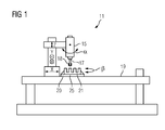
- FIG. 1 schematically a machine tool 11 is shown.
- the machine tool 11 has, in the exemplary embodiment, five machine axes, by means of which a relative movement between a tool 18, which in the exemplary embodiment is in the form of a milling cutter, and a workpiece 21 can be performed.
- the tool 18 is clamped in a tool holder 17, which is rotationally driven by a motor 15.
- the motor 15 and thus the tool 18 can be in for clarity FIG. 1 not shown drives in the X, Y and Z direction translational move and rotate in the direction ⁇ .
- the workpiece 21 can be rotated by means of a driven rotary table 25 in the direction ⁇ .
- the rotary table 25 is rotatably mounted on a stationary machine frame 19.
- the workpiece 21 is fixed by a clamping device 20 on the rotary table 25.
- the machine tool 11 thus has five machine axes, i. It is a so-called 5-axis machine tool.
- machine tool according to the invention may of course also have more or fewer than five machine axes.
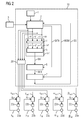
- FIG. 2 are in the form of a block diagram of an inventive device 10 for controlling a machine tool, that is shown in the context of the embodiment of the machine tool 11, and the drives for moving the tool and the workpiece.
- the device 10 has a control unit 2, which uses a part program 3 and / or a manual operation input to determine desired movement values x, y, z and ov for controlling a relative movement taking place between the tool 18 and the workpiece 21.
- the control unit 2 determines the movement target values on the basis of the part program 3, in which the movement to be performed by the tool with respect to the workpiece is defined in the form of commands.
- the movement of the tool and / or the workpiece can also be predetermined by an operator on site at the machine tool by means of a manual operation input, which is input via an operating device 1.
- the operating device 1 may be e.g. to act a handwheel and / or a keyboard.
- the part program 3 is usually generated by a CAM / CAD system and a possibly the CAM / CAD system connected downstream so-called post-processor.
- the movement of the tool 18 in relation to a stationary workpiece 21 is defined (see FIG. 3 ).
- the tool 18 is thereby moved along a movement path S.
- the desired movement values which are determined by the control unit 2, are within the scope of the exemplary embodiment in the form of position command values x, y and z, which are the movement of the tool center point TP of the tool 18 in the X, Y and Z directions. ie in 3-dimensional space, describe.
- the tool center point TP is a point preferably defined on the axis of rotation of the tool 18.
- orientation vector values ov are also determined by the control unit 2 as desired movement values, which indicate the orientation of the orientation vector OV of the tool and thus the orientation of the tool in 3-dimensional space when the tool 18 is moved on the movement path S.
- the position and orientation of the tool with respect to the workpiece on the movement path S for each point of the movement path S is defined.
- the motion command values are supplied from the control unit 2 to a brake end determination unit 27 and within these to a first calculation unit 4 as input variables.
- the first calculation unit 4 of the brake end determination unit 27 determines from the current movement target values x, y, z and ov respectively expected future target movement values x ', y', z 'and ov'.
- the future movement values are determined by extrapolation from the motion setpoints currently generated by the control unit 2 and from the movement setpoints that are still in the past.
- the speed of the tool in each direction can be calculated and from this speed an expected future position of the tool can be determined.
- the orientation of the orientation vector of the tool can also be extrapolated into the future.
- the movement command values are only a so-called interpolation cycle of the control unit, i. usually only a few milliseconds in the future, calculated in advance.
- the expected future movement target values thus agree very precisely with the actual future target movement values, which are generated by the control unit 2 in the next interpolation cycle.
- the expected future movement setpoints can also be further in the future than just a few milliseconds.
- the expected future movement setpoint values x ', y', z 'and ov' are then transmitted to a second calculation unit 5 of the brake end determination unit 27.
- the second calculation unit 5 uses the expected future movement setpoint values x ', y', z 'and ov' to determine a brake end arrangement BA of the tool 18.
- the brake end arrangement BA indicates the position and orientation of the tool when the relative movement between the tool and workpiece is at a standstill if based on the expected future motion setpoints a braking of the relative movement between the tool and the workpiece would be carried out until the relative movement stopped.
- the brake end arrangement BA is then transmitted to a tool model determination unit 6, which determines a tool model WM on the basis of the brake end arrangement BA and a tool shape model WMF describing the geometric shape of the tool.
- the tool model WM thus describes, in the context of the exemplary embodiment, the geometric shape of the tool, the position of the tool and the orientation of the tool.
- the control unit 2 transmits the tool shape model WFM of the tool to the tool model determination unit 6.
- the tool shape model is stored in a memory of the device 10.
- the tool model WM is subsequently transmitted to a checking unit 7.
- the checking unit 7 checks whether the tool model WM overlaps with a given workpiece model WSM describing a geometric shape of the workpiece.
- the workpiece model WSM is stored in the device 10 in a memory and is transmitted from the control unit 2 to the verification unit 7.
- the workpiece model WSM is preferably in the form of the CAD model (Computer Aided Design) of the finished workpiece machined on the relevant machine tool.
- the workpiece model can therefore be provided preferably by the CAD system.
- the geometric shape of the workpiece may, for example, be in the form of a geometric final shape of the workpiece.
- the workpiece model can be present, for example, in the form of the geometry of the workpiece, which is present after the machining controlled by the parts program 3 or in shape, in particular if the workpiece is machined on several machine tools and / or by means of several part programs, the geometric shape, the Having the workpiece after editing a part of the part programs or all parts programs on the machine tool or machine tools.
- the predetermined workpiece model WM describes a geometric shape that the workpiece at a certain intermediate processing step.
- the workpiece model may be loaded into the memory of device 10 prior to commencement of processing.
- the tool shape model WFM and the workpiece model WSM are fixed predetermined models and thus do not change during machining of the workpiece by the tool.
- the checking unit 7 determines that the tool model WM intersects with the workpiece model WSM, the checking unit 7 effects a braking of the relative movement between the tool and the workpiece until the relative movement stops. For this purpose, the checking unit 7 generates a brake signal BS in the event of an overlap of the tool model and the workpiece model and transmits this to the control unit 2, which causes a deceleration of the relative movement until the relative movement stops, via a corresponding generation of desired movement values.
- the motion command values are transmitted to a coordinate transformation unit 28, corresponding to the kinematics of the machine tool, ie the machine axes of the machine tool actually available for movement of the tool and / or the workpiece , Position command values x soll , y soll , z soll , ⁇ soll and ⁇ soll should be generated as control setpoints for controlling the movement of the drives to move the machine axes.
- the workpiece and / or the tool for realizing the relative movement between the workpiece and the tool is moved. For example, if the machine tool has a kinematics in which only the workpiece can be moved while the tool is stationary, the workpiece is moved to realize the relative movement between the workpiece and the tool.
- the position command values for the control of the drives are transmitted to the respective associated controller 8a, 8b, 8c, 8d and 8e, which drive correspondingly assigned converters 22a, 22b, 22c, 22d and 22e.
- the converters supply a respective associated electric motor 23a, 23b, 23c, 23d and 23e, each driving a machine axis.
- actual position values x is , y is , z is , ⁇ is and ⁇ is transmitted as control actual values for regulating the drives to the controls 8a, 8b, 8c, 8d and 8e.
- the method according to the invention for avoiding an unwanted collision thus operates in time parallel to the movement of the tool and / or the workpiece actually carried out on the machine.
- no complex simulation for the realization of the collision avoidance is necessary. It is thus no longer necessary after the start of processing the parts program, in which for a certain time a simulation is calculated in advance, before the actual real machining of the workpiece can be started. The processing time for machining the workpiece is thus reduced by the invention.
- the method preferably only determines expected movement target values over a relatively short period of time in the future, it works with high precision, so that no safety distances between workpiece and tool are necessary and thus the method is also used in the production of very small and especially filigree workpieces can.
- control unit 2 the brake end arrangement determining unit 27, the tool modeling averaging unit 6, the checking unit 7 and the coordinate transformation unit 28 are in the form of program code sections executed on one or more processors.
Landscapes
- Engineering & Computer Science (AREA)
- Human Computer Interaction (AREA)
- Manufacturing & Machinery (AREA)
- Physics & Mathematics (AREA)
- General Physics & Mathematics (AREA)
- Automation & Control Theory (AREA)
- Numerical Control (AREA)
Abstract
Description
- Verfahren zur Vermeidung einer ungewollten Kollision zwischen einem Werkzeug und einem Werkstück bei einer Werkzeugmaschine
- Die Erfindung betrifft ein Verfahren zur Vermeidung einer ungewollten Kollision zwischen einem Werkzeug und einem Werkstück bei einer Werkzeugmaschine. Weiterhin betrifft die Erfindung eine Einrichtung zur Steuerung einer Werkzeugmaschine.
- Bei der Bearbeitung von Werkstücken mittels Werkzeugmaschinen müssen ungewollte Kollisionen zwischen dem Werkzeug und dem Werkstück, die zu einer Zerstörung des Werkzeugs und/oder des Werkstücks führen können, vermieden werden. Dabei kommt es, insbesondere wenn die eigentliche z.B. spanende Bearbeitung des Werkstücks durch das Werkzeug schon beendet ist, zu Beschädigungen des Werkstücks durch das Werkzeug, da oftmals das Werkzeug und/oder das Werkstück im Handbetrieb voneinander weg bewegt werden, um das fertig bearbeitete Werkstück aus der Werkzeugmaschine entnehmen zu können. Dabei können zur Realisierung der vom Bediener per Hand vorgegebenen Bewegung die Maschinenachsen im sogenannten Interpolationsverbund arbeiten und sich so mehrere Maschinenachsen zur Bewegung des Werkstücks und/oder des Werkzeugs gleichzeitig bewegen, so dass der Bediener oftmals schwer einschätzen kann, wie eine per Hand eingegebene Bewegungsvorgabe von der Werkzeugmaschine umgesetzt wird. Dies führt des Öfteren zu Beschädigungen, insbesondere des Werkstücks, da das Werkstück, z.B. beim Wegfahren des Werkzeugs vom Werkzeug angekratzt wird. Eine oft über mehrere Stunden oder gar Tage andauernde Bearbeitung auf der Werkzeugmaschine war dann umsonst, da das Werkstück nicht mehr brauchbar ist.
- Weiterhin werden auch Teileprogramme, die z.B. von einem CAD/CAM-System (Computer Aided Design/Computer Aided Manufacturing) erzeugt wurden, insbesondere am Programmende von Hand mit Steuerbefehlen ergänzt, die nach der Bearbeitung des Werkstücks das Werkzeug und das Werkstück voneinander weg bewegen sollen, damit das Werkstück aus der Werkzeugmaschine entnommen werden kann. Auch hierbei passieren oft Fehler, die zur Beschädigung des Werkstücks oder des Werkzeugs führen.
- Aus der Veröffentlichung "Gegen den Kollisionskurs", "Antriebspraxis 02/2007, ist ein Kollisionsvermeidungssystem bekannt, bei dem mittels einer Simulation während der Bearbeitung des Werkstücks ein Werkstückmodell berechnet wird und anhand diesem eine Kollisionsvermeidung realisiert wird. Die Berechnung einer Simulation benötigt aber sehr viel Rechenzeit, so dass zum einen eine hohe Rechenleistung zur Durchführung eines solchen Kollisionsvermeidungssystems benötigt wird und zum anderen bevor mit der realen Bearbeitung des Werkstücks begonnen werden kann, die Simulation des Werkstücks mit einem zeitlichen Vorsprung vor dem Beginn der realen Werkstückbearbeitung ablaufen werden muss, da die Ermittelung des Werkstückmodells in der Regel trotz der hohen Rechenleistung nicht zeitgleich zur realen Bearbeitung des Werkstücks ablauffähig ist. In der Praxis führt dies dazu, dass wenn der Bediener den Startknopf zur Bearbeitung drückt, sich erst einmal an der Werkzeugmaschine nichts tut, da die Werkzeugmaschine zunächst über einen gewissen Zeitraum die bei der Bearbeitung des Werkstücks durch das Werkzeug entstehende aktuelle geometrische Werkstückform, d.h. das Werkstückmodell im Voraus berechnen muss. Hierdurch erhöht sich die Bearbeitungszeit für das Werkstück. Weiterhin werden insbesondere bei einer Bedienung per Hand relativ große Sicherheitsabstände zwischen Werkstück und Werkzeug benötigt.
- Es ist Aufgabe der Erfindung, ein Verfahren zur Vermeidung einer ungewollten Kollision zwischen einem Werkzeug und einem Werkstück bei einer Werkzeugmaschine sowie eine Einrichtung zur Steuerung einer Werkzeugmaschine zu schaffen, die eine kurze Bearbeitungszeit des Werkstücks ermöglichen.
- Diese Aufgabe wird gelöst durch ein Verfahren zur Vermeidung einer ungewollten Kollision zwischen einem Werkzeug und einem Werkstück bei einer Werkzeugmaschine, wobei Bewegungssollwerte zur Steuerung einer Relativbewegung zwischen Werkzeug und Werkstück ermittelt werden, wobei anhand der Bewegungssollwerte zu erwartende zukünftige Bewegungssollwerte ermittelt werden, wobei anhand der zu erwartenden zukünftigen Bewegungssollwerte eine Bremsendanordnung des Werkzeugs ermittelt wird, wobei anhand der Bremsendanordnung des Werkzeugs und eines die geometrische Form des Werkzeugs beschreibenden Werkzeugformmodells ein Werkzeugmodell ermittelt wird, wobei überprüft wird, ob das Werkzeugmodel sich mit einem eine geometrische Form des Werkstücks beschreibenden vorgegebenen Werkstückmodells überschneidet, wobei im Falle einer festgestellten Überschneidung ein Abbremsen der Relativbewegung zwischen Werkzeug und Werkstück bis zum Stillstand der Relativbewegung bewirkt wird.
- Weiterhin wird diese Aufgabe gelöst durch eine Einrichtung zur Steuerung einer Werkzeugmaschine, wobei die Einrichtung aufweist:
- eine Steuereinheit, die zur Ermittlung von Bewegungssollwerten zur Steuerung einer Relativbewegung zwischen einem Werkzeug und einem Werkstück ausgebildet ist,
- eine Bremsendanordnungsermittlungseinheit, die zur Ermittlung von zu erwartenden zukünftigen Bewegungssollwerten anhand der Bewegungssollwerte ausgebildet ist, wobei die Bremsendanordnungsermittlungseinheit ausgebildet ist anhand der zu erwartenden zukünftigen Bewegungssollwerte eine Bremsendanordnung des Werkzeugs zu ermitteln,
- eine Werkzeugmodellermittelungseinheit, die zur Ermittlung eines Werkzeugmodells anhand der Bremsendanordnung und eines die geometrische Form des Werkzeugs beschreibenden Werkzeugformmodells ausgebildet ist und
- eine Überprüfungseinheit, die zur Überprüfung, ob das Werkzeugmodell sich mit einem eine geometrische Form des Werkstücks beschreibenden vorgegebenen Werkstückmodells überschneidet, ausgebildet ist, wobei die Überprüfungseinheit ausgebildet ist, im Falle einer festgestellten Überschneidung eine Abbremsung der Relativbewegung zwischen Werkzeug und Werkstück bis zum Stillstand der Relativbewegung zu bewirken.
- Die Erfindung benötigt keine Sicherheitsabstände zwischen Werkzeug und Werkstück, so dass das erfindungsgemäße Verfahren auch bei sehr filigranen, und insbesondere kleinen Werkstücken durchgeführt werden kann.
- Vorteilhafte Ausbildungen der Erfindung ergeben sich aus den abhängigen Ansprüchen. Vorteilhafte Ausbildungen des Verfahrens ergeben sich analog zu vorteilhaften Ausbildungen der Einrichtung und umgekehrt.
- Es erweist sich als vorteilhaft, wenn die Bewegungssollwerte zur Steuerung einer Relativbewegung zwischen Werkzeug und Werkstück anhand eines Teileprogramms und/oder anhand einer Handbedieneingabe ermittelt werden. Eine Ermittlung der Bewegungssollwerte anhand eines Teileprogramms und/oder einer Handbedienung stellt eine übliche Vorgabe einer durchzuführenden Bewegung dar.
- Ferner erweist es sich als vorteilhaft, wenn das Werkstückmodell in Form eines CAD-Modells vorliegt, da das Werkstückmodell mittels eines CAD-Systems besonders leicht erzeugt werden kann.
- Die Einrichtung zur Steuerung einer Werkzeugmaschine kann dabei z.B. in Form einer CNC-Steuerung vorliegen, wobei die CNC-Steuerung z.B. in Form einer Recheneinheit vorliegen kann, auf der ein Computerprogramm mit Programmcode zur Durchführung des erfindungsgemäßen Verfahrens ausgeführt wird. Die Recheneinheit kann dabei eine oder mehrere Prozessoren aufweisen, auf denen das Computerprogramm abläuft.
- Ein Ausführungsbeispiel der Erfindung ist in der Zeichnung dargestellt und wird im Folgenden näher erläutert. Darin zeigen:
- FIG 1
- eine Werkzeugmaschine,
- FIG 2
- eine erfindungsgemäße Einrichtung zur Steuerung einer Werkzeugmaschine und
- FIG 3
- eine Bewegungsbahn S, entlang der ein Werkzeug zur Bearbeitung eines Werkstücks bewegt wird.
- In
FIG 1 ist schematisiert eine Werkzeugmaschine 11 dargestellt. Die Werkzeugmaschine 11 verfügt im Rahmen des Ausführungsbeispiels über fünf Maschinenachsen, durch die eine Relativbewegung zwischen einem Werkzeug 18, das im Rahmen des Ausführungsbeispiels in Form eines Fräsers vorliegt, und einem Werkstück 21 durchgeführt werden kann. Das Werkzeug 18 ist dabei in eine Werkzeugaufnahme 17 eingespannt, die von einem Motor 15 rotatorisch angetrieben wird. Der Motor 15 und damit das Werkzeug 18 lassen sich mit der Übersichtlichkeit halber inFIG 1 nicht dargestellten Antrieben in X-, Y- und Z-Richtung translatorisch bewegen und in Richtung α drehen.
Weiterhin kann das Werkstück 21 mit Hilfe eines angetriebenen Rundtischs 25 in Richtung β gedreht werden. Der Rundtisch 25 ist dabei auf einem ruhenden Maschinengestell 19 drehbar gelagert. - Das Werkstück 21 ist durch eine Einspannvorrichtung 20 am Rundtisch 25 befestigt.
- Die Werkzeugmaschine 11 weist somit fünf Maschinenachsen auf, d.h. es handelt sich um eine sogenannte 5-achsige Werkzeugmaschine.
- Es sei dabei an dieser Stelle angemerkt, dass die erfindungsgemäße Werkzeugmaschine selbstverständlich auch noch mehr oder weniger als fünf Maschinenachsen aufweisen kann.
- In
FIG 2 sind in Form eines Blockschaltbilds eine erfindungsgemäße Einrichtung 10 zur Steuerung einer Werkzeugmaschine, d.h. im Rahmen des Ausführungsbeispiels der Werkzeugmaschine 11, sowie die Antriebe zur Bewegung des Werkzeugs und des Werkstücks dargestellt. - Die Einrichtung 10 weist eine Steuereinheit 2 auf, die anhand eines Teileprogramms 3 und/oder einer Handbedieneingabe Bewegungssollwerte x, y, z und ov zur Steuerung einer zwischen dem Werkzeug 18 und dem Werkstück 21 stattfindenden Relativbewegung, ermittelt. Die Steuereinheit 2 ermittelt die Bewegungssollwerte anhand des Teileprogramms 3, in dem die vom Werkzeug in Bezug zum Werkstück durchzuführende Bewegung in Form von Befehlen definiert ist. Alternativ oder zusätzlich kann die Bewegung des Werkzeug und/oder das Werkstücks auch mittels einer Handbedieneingabe, welche über eine Bedieneinrichtung 1 eingegeben wird, von einem Bediener vor Ort an der Werkzeugmaschine vorgegeben werden. Bei der Bedieneinrichtung 1 kann es sich z.B. um ein Handrad und/oder eine Tastatur handeln.
- Das Teileprogramm 3 wird dabei üblicherweise von einem CAM/CAD-System und einem eventuell dem CAM/CAD-System nach geschalteten sogenannten Postprozessor erzeugt. Im Teileprogramm ist dabei die Bewegung des Werkzeugs 18 im Bezug zu einem ruhenden Werkstück 21 definiert (siehe
FIG 3 ). Das Werkzeug 18 wird dabei längs einer Bewegungsbahn S bewegt. Die Bewegungssollwerte, welche von der Steuereinheit 2 ermittelt werden, liegen dabei im Rahmen des Ausführungsbeispiels in Form von Lagesollwerten x, y und z, die die Bewegung des so genannten Toolcenter Points TP des Werkzeugs 18 in X-, Y- und Z-Richtung, d.h. im 3-dimensionalen Raum, beschreiben. Der Toolcenter Point TP ist dabei ein vorzugsweise auf der Rotationsachse des Werkzeugs 18 definierter Punkt. Weiterhin werden von der Steuereinheit 2 als Bewegungssollwerte auch Orientierungsvektorwerte ov ermittelt, die die Orientierung des Orientierungsvektors OV des Werkzeugs und damit die Ausrichtung des Werkzeugs im 3-dimensionalen Raum angeben, wenn das Werkzeug 18 auf der Bewegungsbahn S bewegt wird. - Durch die Bewegungssollwerte ist die Lage und Orientierung des Werkzeugs im Bezug zum Werkstück auf der Bewegungsbahn S für jeden Punkt der Bewegungsbahn S definiert.
- Die Bewegungssollwerte werden von der Steuereinheit 2 an eine Bremsendanordungsermittlungseinheit 27 und innerhalb dieser an eine erste Berechnungseinheit 4 als Eingangsgrößen zugeführt. Die erste Berechnungseinheit 4 der Bremsendanordungsermittlungseinheit 27 ermittelt aus den aktuellen Bewegungssollwerten x, y, z und ov jeweils zu erwartende zukünftige Bewegungssollwerte x', y', z' und ov'. Die zukünftigen Bewegungswerte werden dabei im Rahmen des Ausführungsbeispiels durch Extrapolation aus den aktuell von der Steuereinheit 2 erzeugten Bewegungssollwerten und aus weiter in der Vergangenheit liegenden Bewegungssollwerten ermittelt. So kann z.B. aus den aktuellen Bewegungssollwerten und den in der Vergangenheit liegenden Bewegungssollwerten die Geschwindigkeit des Werkzeugs in jeder Richtung berechnet werden und anhand dieser Geschwindigkeit eine zu erwartende zukünftige Lage des Werkzeugs ermittelt werden. In analoger Weise kann auch die Orientierung des Orientierungsvektors des Werkzeugs in die Zukunft extrapoliert werden. Vorzugsweise werden dabei die Bewegungssollwerte nur um einen sogenannten Interpolationstakt der Steuereinheit, d.h. in der Regel nur um wenige Millisekunden in die Zukunft, voraus berechnet. Die zu erwartenden zukünftigen Bewegungssollwerte stimmen somit sehr genau mit den tatsächlichen zukünftigen Bewegungssollwerten überein, welche im nächsten Interpolationstakt von der Steuereinheit 2 erzeugt werden. Selbstverständlich können die zu erwartenden zukünftigen Bewegungssollwerte aber auch weiter in der Zukunft liegen als nur wenige Millisekunden.
- Die zu erwartenden zukünftigen Bewegungssollwerte x', y', z' und ov' werden anschließend an eine zweite Berechnungseinheit 5 der Bremsendanordungsermittlungseinheit 27 übermittelt. Die zweite Berechnungseinheit 5 ermittelt anhand der zu erwartenden zukünftigen Bewegungssollwerte x', y', z' und ov' eine Bremsendanordnung BA des Werkzeugs 18. Die Bremsendanordnung BA gibt dabei die Lage und die Orientierung des Werkzeugs bei Stillstand der Relativbewegung zwischen Werkzeug und Werkstück an, wenn anhand den zu erwartenden zukünftigen Bewegungssollwerten eine Bremsung der Relativbewegung zwischen Werkzeug und Werkstück bis zum Stillstand der Relativbewegung durchgeführt werden würde. Die Bremsendanordnung BA wird anschließend an eine Werkzeugmodellermittelungseinheit 6 übermittelt, die anhand der Bremsendanordnung BA und ein die geometrische Form des Werkzeugs beschreibendes Werkzeugformmodell WMF ein Werkzeugmodell WM ermittelt. Das Werkzeugmodell WM beschreibt somit, im Rahmen des Ausführungsbeispiels, die geometrische Form des Werkzeugs, die Lage des Werkzeugs sowie die Orientierung des Werkzeugs.
- Die Steuereinheit 2 übermittelt hierzu das Werkzeugformmodell WFM des Werkzeugs an die Werkzeugmodellermittelungseinheit 6. Das Werkzeugformmodell ist dabei in einem Speicher der Einrichtung 10 gespeichert. Das Werkzeugmodell WM wird anschließend an eine Überprüfungseinheit 7 übermittelt. Die Überprüfungseinheit 7 prüft, ob das Werkzeugmodell WM sich mit einem eine geometrische Form des Werkstücks beschreibenden vorgegebenen Werkstückmodells WSM überschneidet. Das Werkstückmodell WSM ist dabei in der Einrichtung 10 in einem Speicher abgespeichert und wird von der Steuereinheit 2 an die Überprüfungseinheit 7 übermittelt. Das Werkstückmodell WSM liegt dabei vorzugsweise in Form des CAD-Modells (Computer Aided Design) des fertig an der betreffenden Werkzeugmaschine bearbeiteten Werkstücks vor. Das Werkstückmodell kann somit vorzugweise vom CAD-System zur Verfügung gestellt werden. Die geometrische Form des Werkstücks kann z.B. in Form einer geometrischen Endform des Werkstücks vorliegen. Das Werkstückmodell kann dabei z.B. in Form der Geometrie des Werkstücks vorliegen, die nach Ablauf der vom Teileprogramm 3 gesteuerten Bearbeitung vorliegt oder aber in Form, insbesondere wenn das Werkstück auf mehreren Werkzeugmaschinen und/oder mittels mehrerer Teileprogramme hintereinander bearbeitet wird, der geometrischen Form, die das Werkstück nach dem Bearbeiten eines Teils der Teileprogramme oder von allen Teileprogrammen auf der Werkzeugmaschine oder den Werkzeugmaschinen aufweist. Es ist aber auch möglich, dass das vorgegebene Werkstückmodell WM eine geometrische Form beschreibt, die das Werkstück bei einem bestimmten Bearbeitungszwischenschritt annimmt. Das Werkstückmodell kann z.B. vor Beginn der Bearbeitung in den Speicher der Einrichtung 10 geladen werden.
- Das Werkzeugformmodell WFM und das Werkstückmodell WSM sind feststehende vorgegebene Modelle und verändern sich somit während der Bearbeitung des Werkstücks durch das Werkzeug nicht.
- Wenn die Überprüfungseinheit 7 feststellt, dass sich das Werkzeugmodell WM mit dem Werkstückmodell WSM überschneidet, wird von der Überprüfungseinheit 7 ein Abbremsen der Relativbewegung zwischen Werkzeug und Werkstück bis zum Stillstand der Relativbewegung bewirkt. Die Überprüfungseinheit 7 erzeugt hierzu im Falle einer Überschneidung von Werkzeugmodell und Werkstückmodell ein Bremssignal BS und übermittelt dieses an die Steuereinheit 2, die über eine entsprechende Erzeugung von Bewegungssollwerten eine Abbremsung der Relativbewegung bis zum Stillstand der Relativbewegung bewirkt.
- Zeitlich gesehen parallel zu der Übermittlung der Bewegungssollwerte von der Steuereinheit 2 an die Bremsendanordungsermittlungseinheit 27 werden die Bewegungssollwerte an eine Koordinatentransformationseinheit 28 übermittelt, die entsprechend der Kinematik der Werkzeugmaschine, d.h. der tatsächlich zur Bewegung des Werkzeugs und/oder des Werkstücks zur Verfügung stehenden Maschinenachsen der Werkzeugmaschine, Lagesollwerte xsoll, ysoll, zsoll, αsoll und βsollals Regelsollwerte zur Steuerung der Bewegung der Antriebe zur Bewegung der Maschinenachsen, erzeugt. Je nach dem, wie die Kinematik der Werkzeugmaschine ausgebildet ist, wird das Werkstück und/oder das Werkzeug zur Realisierung der Relativbewegung zwischen Werkstück und Werkzeug bewegt. So wird z.B. wenn die Werkzeugmaschine eine Kinematik aufweist, bei der nur das Werkstück bewegt werden kann, während das Werkzeug ruhend angeordnet ist, das Werkstück zur Realisierung der Relativbewegung zwischen Werkstück und Werkzeug bewegt.
- Die Lagesollwerte zur Steuerung der Antriebe werden an die jeweilige zugehörige Regelung 8a, 8b, 8c, 8d und 8e übermittelt, die entsprechend zugeordnete Stromrichter 22a, 22b, 22c, 22d und 22e ansteuern. Die Stromrichter versorgen einen jeweils zugeordneten Elektromotor 23a, 23b, 23c, 23d und 23e, die jeweils eine Maschinenachse antreiben. Dabei werden von Lagegebern, die der Übersichtlichkeit halber in
FIG 2 nicht dargestellt sind, Lageistwerte xist, yist, zist, αist und βist als Regelistwerte zur Regelung der Antriebe an die Regelungen 8a, 8b, 8c, 8d und 8e übermittelt. - Das erfindungsgemäße Verfahren zur Vermeidung einer ungewollten Kollision arbeitet somit zeitlich parallel zur tatsächlich an der Maschine durchgeführten Bewegung des Werkzeugs und/oder des Werkstücks. Bei der Erfindung ist keine aufwändige Simulation zur Realisierung der Kollisionsvermeidung notwendig. Es ist somit kein Zeitraum nach Start der Abarbeitung des Teileprogamms mehr notwendig, in dem für eine gewisse Zeit lang eine Simulation im Voraus berechnet wird, bevor mit der eigentlichen realen Bearbeitung des Werkstücks begonnen werden kann. Die Bearbeitungszeit zur Bearbeitung des Werkstücks wird somit durch die Erfindung reduziert.
- Da das Verfahren vorzugsweise nur über eine relativ kleine Zeitspanne in der Zukunft liegende zu erwartende Bewegungssollwerte ermittelt, arbeitet es hochgenau, so dass keine Sicherheitsabstände zwischen Werkstück und Werkzeug notwendig sind und somit das Verfahren auch bei der Fertigung von sehr kleinen und insbesondere filigranen Werkstücken eingesetzt werden kann.
- Es sei an dieser Stelle angemerkt, dass im Rahmen des Ausführungsbeispiels die Steuereinheit 2, die Bremsendanordnungsermittlungseinheit 27, die Werkzeugmodellermittelungseinheit 6, die Überprüfungseinheit 7 und die Koordinatentransformationseinheit 28 in Form von Programmcodeabschnitten vorliegen, die auf einem oder mehreren Prozessoren ausgeführt werden.
Claims (6)
- Verfahren zur Vermeidung einer ungewollten Kollision zwischen einem Werkzeug (18) und einem Werkstück (21) bei einer Werkzeugmaschine (11), wobei Bewegungssollwerte (x,y,z,ov) zur Steuerung einer Relativbewegung zwischen Werkzeug (18) und Werkstück (21) ermittelt werden, wobei anhand der Bewegungssollwerte (x,y,z,ov) zu erwartende zukünftige Bewegungssollwerte (x',y',z',ov') ermittelt werden, wobei anhand der zu erwartenden zukünftigen Bewegungssollwerte (x',y',z',ov') eine Bremsendanordnung (BA) des Werkzeugs (18) ermittelt wird, wobei anhand der Bremsendanordnung (BA) des Werkzeugs (18) und eines die geometrische Form des Werkzeugs (18) beschreibenden Werkzeugformmodells (WFM) ein Werkzeugmodell (WM) ermittelt wird, wobei überprüft wird, ob das Werkzeugmodel (WM) sich mit einem eine geometrische Form des Werkstücks beschreibenden vorgegebenen Werkstückmodells (WM) überschneidet, wobei im Falle einer festgestellten Überschneidung ein Abbremsen der Relativbewegung zwischen Werkzeug (18) und Werkstück (21) bis zum Stillstand der Relativbewegung bewirkt wird.
- Verfahren nach Anspruch 1,
dadurch gekennzeichnet, dass die Bewegungssollwerte (x,y,z,ov) zur Steuerung einer Relativbewegung zwischen Werkzeug (18) und Werkstück (21) anhand eines Teileprogramms (3) und/oder anhand einer Handbedieneingabe ermittelt werden. - Verfahren nach einem der vorhergehenden Ansprüche,
dadurch gekennzeichnet, dass das Werkstückmodell (WSM) in Form eines CAD-Modells vorliegt. - Computerprogramm mit Programmcode zur Durchführung eines Verfahrens nach einem der vorhergehenden Ansprüche, wenn das Computerprogramm von einer Recheneinheit ausgeführt wird.
- Einrichtung zur Steuerung einer Werkzeugmaschine (11), wobei die Einrichtung aufweist:- eine Steuereinheit (2), die zur Ermittlung von Bewegungssollwerten (x,y,z,ov) zur Steuerung einer Relativbewegung zwischen einem Werkzeug (18) und einem Werkstück (21) ausgebildet ist,- eine Bremsendanordnungsermittlungseinheit (27), die zur Ermittlung von zu erwartenden zukünftigen Bewegungssollwerten (x',y',z',ov') anhand der Bewegungssollwerte (x, y, z, ov) ausgebildet ist, wobei die Bremsendanordnungsermittlungseinheit (27) ausgebildet ist anhand der zu erwartenden zukünftigen Bewegungssollwerte (x',y',z',ov') eine Bremsendanordnung (BA) des Werkzeugs (18) zu ermitteln,- eine Werkzeugmodellermittelungseinheit (6), die zur Ermittlung eines Werkzeugmodells (WM) anhand der Bremsendanordnung (BA) und eines die geometrische Form des Werkzeugs (18) beschreibenden Werkzeugformmodells (WFM) ausgebildet ist und- eine Überprüfungseinheit (7), die zur Überprüfung, ob das Werkzeugmodell (WM) sich mit einem eine geometrische Form des Werkstücks (18) beschreibenden vorgegebenen Werkstückmodells (WSM) überschneidet, ausgebildet ist, wobei die Überprüfungseinheit (7) ausgebildet ist, im Falle einer festgestellten Überschneidung eine Abbremsung der Relativbewegung zwischen Werkzeug (18) und Werkstück (21) bis zum Stillstand der Relativbewegung zu bewirken.
- Werkzeugmaschine (11), wobei die Werkzeugmaschine (11) eine Einrichtung nach Anspruch 5 aufweist.
Priority Applications (1)
| Application Number | Priority Date | Filing Date | Title |
|---|---|---|---|
| EP11162779.0A EP2515192B1 (de) | 2011-04-18 | 2011-04-18 | Verfahren zur Vermeidung einer ungewollten Kollision zwischen einem Werkzeug und einem Werkstück bei einer Werkzeugmaschine |
Applications Claiming Priority (1)
| Application Number | Priority Date | Filing Date | Title |
|---|---|---|---|
| EP11162779.0A EP2515192B1 (de) | 2011-04-18 | 2011-04-18 | Verfahren zur Vermeidung einer ungewollten Kollision zwischen einem Werkzeug und einem Werkstück bei einer Werkzeugmaschine |
Publications (2)
| Publication Number | Publication Date |
|---|---|
| EP2515192A1 true EP2515192A1 (de) | 2012-10-24 |
| EP2515192B1 EP2515192B1 (de) | 2013-12-18 |
Family
ID=44760213
Family Applications (1)
| Application Number | Title | Priority Date | Filing Date |
|---|---|---|---|
| EP11162779.0A Active EP2515192B1 (de) | 2011-04-18 | 2011-04-18 | Verfahren zur Vermeidung einer ungewollten Kollision zwischen einem Werkzeug und einem Werkstück bei einer Werkzeugmaschine |
Country Status (1)
| Country | Link |
|---|---|
| EP (1) | EP2515192B1 (de) |
Cited By (4)
| Publication number | Priority date | Publication date | Assignee | Title |
|---|---|---|---|---|
| US10545477B2 (en) | 2014-05-28 | 2020-01-28 | Fanuc Corporation | Numerical controller having cutting in/out motion inserting function or circular motion inserting function |
| EP3933525A1 (de) | 2020-07-01 | 2022-01-05 | Siemens Aktiengesellschaft | Modelldatenbasierter kollisionsschutz |
| EP3944931A1 (de) | 2020-07-30 | 2022-02-02 | Siemens Aktiengesellschaft | Kollisionsvermeidung mit künstlicher intelligenz |
| EP3958074A1 (de) | 2020-08-17 | 2022-02-23 | Siemens Aktiengesellschaft | Kollisionsvermeidung mit real gemessenen werkzeugdaten |
Citations (1)
| Publication number | Priority date | Publication date | Assignee | Title |
|---|---|---|---|---|
| EP2031471A2 (de) * | 2007-08-28 | 2009-03-04 | Fanuc Ltd | Numerische Steuerung mit Kollisionsprüfungsfunktion |
-
2011
- 2011-04-18 EP EP11162779.0A patent/EP2515192B1/de active Active
Patent Citations (1)
| Publication number | Priority date | Publication date | Assignee | Title |
|---|---|---|---|---|
| EP2031471A2 (de) * | 2007-08-28 | 2009-03-04 | Fanuc Ltd | Numerische Steuerung mit Kollisionsprüfungsfunktion |
Cited By (5)
| Publication number | Priority date | Publication date | Assignee | Title |
|---|---|---|---|---|
| US10545477B2 (en) | 2014-05-28 | 2020-01-28 | Fanuc Corporation | Numerical controller having cutting in/out motion inserting function or circular motion inserting function |
| DE102015006796B4 (de) * | 2014-05-28 | 2020-10-01 | Fanuc Corporation | Numerische Steuerung mit einer Einfügfunktion für eine Hinein-/Heraus-Zerspanbewegung oder mit einer Einfügfunktion für eine kreisrunde Bewegung |
| EP3933525A1 (de) | 2020-07-01 | 2022-01-05 | Siemens Aktiengesellschaft | Modelldatenbasierter kollisionsschutz |
| EP3944931A1 (de) | 2020-07-30 | 2022-02-02 | Siemens Aktiengesellschaft | Kollisionsvermeidung mit künstlicher intelligenz |
| EP3958074A1 (de) | 2020-08-17 | 2022-02-23 | Siemens Aktiengesellschaft | Kollisionsvermeidung mit real gemessenen werkzeugdaten |
Also Published As
| Publication number | Publication date |
|---|---|
| EP2515192B1 (de) | 2013-12-18 |
Similar Documents
| Publication | Publication Date | Title |
|---|---|---|
| EP2515193B1 (de) | Verfahren zur Vermeidung einer ungewollten Kollision zwischen einem Werkzeug und einem Werkstück bei einer Werkzeugmaschine | |
| EP1894068B1 (de) | Verfahren zur qualitätssicherung beim betrieb einer industriellen maschine | |
| DE102017004366B4 (de) | Numerische Steuervorrichtung | |
| EP2058717B1 (de) | Verfahren und Einrichtung zum Betrieb einer Werkzeugmaschine | |
| DE10352815B4 (de) | Simulationsverfahren für eine Bearbeitung eines Werkstücks durch eine Werkzeugmaschine und korrespondierender Rechner | |
| EP2189861B1 (de) | Verfahren zur Erstellung eines Teileprogramms | |
| DE102008001011A1 (de) | Numerische Steuervorrichtung | |
| EP3056322B1 (de) | Verfahren und system zum betreiben einer mehrachsigen maschine, insbesondere eines roboters | |
| EP2919081B1 (de) | Bearbeitungsmaschine mit Berücksichtigung von Lagefehlern bei Kollisionsprüfung | |
| DE102013015234A1 (de) | Verfahren zur Steuerung einer Verzahnmaschine sowie Verzahnmaschine | |
| EP2515192B1 (de) | Verfahren zur Vermeidung einer ungewollten Kollision zwischen einem Werkzeug und einem Werkstück bei einer Werkzeugmaschine | |
| EP2796952A1 (de) | Numerische Steuerung mit Möglichkeit zur Änderung des Teileprogramms | |
| WO2002020213A2 (de) | Werkzeugmaschine mit kollisionsprüfung | |
| DE102005037779B4 (de) | Numerische Steuereinheit | |
| DE102018003638A1 (de) | Numerische Steuerung | |
| DE102017222137B4 (de) | Numerische Steuervorrichtung | |
| EP3309635A1 (de) | Ermittlung eines für eine jeweilige bearbeitungsmaschine optimierten teileprogramms | |
| EP3367185A1 (de) | Antriebssystem und dessen beurteilung | |
| DE102015012147B4 (de) | Numerische Steuervorrichtung | |
| EP3300521B1 (de) | Ausrichtungsverfahren für werkstücke | |
| DE102017011654B4 (de) | Numerische Steuervorrichtung | |
| EP3045993A1 (de) | Fertigungssystem mit zusätzlicher Funktionalität und Betriebsverfahren | |
| EP3890928B1 (de) | Kraftbegrenztes verfahren mindestens eines elements einer produktionsmaschine im manuellen betrieb | |
| EP3944931A1 (de) | Kollisionsvermeidung mit künstlicher intelligenz | |
| EP4057088A1 (de) | Sicherer betrieb einer mehrachskinematik |
Legal Events
| Date | Code | Title | Description |
|---|---|---|---|
| PUAI | Public reference made under article 153(3) epc to a published international application that has entered the european phase |
Free format text: ORIGINAL CODE: 0009012 |
|
| AK | Designated contracting states |
Kind code of ref document: A1 Designated state(s): AL AT BE BG CH CY CZ DE DK EE ES FI FR GB GR HR HU IE IS IT LI LT LU LV MC MK MT NL NO PL PT RO RS SE SI SK SM TR |
|
| AX | Request for extension of the european patent |
Extension state: BA ME |
|
| RAP1 | Party data changed (applicant data changed or rights of an application transferred) |
Owner name: SIEMENS AKTIENGESELLSCHAFT |
|
| 17P | Request for examination filed |
Effective date: 20130424 |
|
| GRAP | Despatch of communication of intention to grant a patent |
Free format text: ORIGINAL CODE: EPIDOSNIGR1 |
|
| INTG | Intention to grant announced |
Effective date: 20130718 |
|
| GRAS | Grant fee paid |
Free format text: ORIGINAL CODE: EPIDOSNIGR3 |
|
| GRAA | (expected) grant |
Free format text: ORIGINAL CODE: 0009210 |
|
| AK | Designated contracting states |
Kind code of ref document: B1 Designated state(s): AL AT BE BG CH CY CZ DE DK EE ES FI FR GB GR HR HU IE IS IT LI LT LU LV MC MK MT NL NO PL PT RO RS SE SI SK SM TR |
|
| REG | Reference to a national code |
Ref country code: GB Ref legal event code: FG4D Free format text: NOT ENGLISH |
|
| REG | Reference to a national code |
Ref country code: CH Ref legal event code: EP |
|
| REG | Reference to a national code |
Ref country code: AT Ref legal event code: REF Ref document number: 645884 Country of ref document: AT Kind code of ref document: T Effective date: 20140115 |
|
| REG | Reference to a national code |
Ref country code: IE Ref legal event code: FG4D Free format text: LANGUAGE OF EP DOCUMENT: GERMAN |
|
| REG | Reference to a national code |
Ref country code: DE Ref legal event code: R096 Ref document number: 502011001828 Country of ref document: DE Effective date: 20140213 |
|
| REG | Reference to a national code |
Ref country code: NL Ref legal event code: VDEP Effective date: 20131218 |
|
| PG25 | Lapsed in a contracting state [announced via postgrant information from national office to epo] |
Ref country code: NO Free format text: LAPSE BECAUSE OF FAILURE TO SUBMIT A TRANSLATION OF THE DESCRIPTION OR TO PAY THE FEE WITHIN THE PRESCRIBED TIME-LIMIT Effective date: 20140318 Ref country code: LT Free format text: LAPSE BECAUSE OF FAILURE TO SUBMIT A TRANSLATION OF THE DESCRIPTION OR TO PAY THE FEE WITHIN THE PRESCRIBED TIME-LIMIT Effective date: 20131218 Ref country code: FI Free format text: LAPSE BECAUSE OF FAILURE TO SUBMIT A TRANSLATION OF THE DESCRIPTION OR TO PAY THE FEE WITHIN THE PRESCRIBED TIME-LIMIT Effective date: 20131218 Ref country code: HR Free format text: LAPSE BECAUSE OF FAILURE TO SUBMIT A TRANSLATION OF THE DESCRIPTION OR TO PAY THE FEE WITHIN THE PRESCRIBED TIME-LIMIT Effective date: 20131218 Ref country code: SE Free format text: LAPSE BECAUSE OF FAILURE TO SUBMIT A TRANSLATION OF THE DESCRIPTION OR TO PAY THE FEE WITHIN THE PRESCRIBED TIME-LIMIT Effective date: 20131218 |
|
| REG | Reference to a national code |
Ref country code: LT Ref legal event code: MG4D |
|
| PG25 | Lapsed in a contracting state [announced via postgrant information from national office to epo] |
Ref country code: LV Free format text: LAPSE BECAUSE OF FAILURE TO SUBMIT A TRANSLATION OF THE DESCRIPTION OR TO PAY THE FEE WITHIN THE PRESCRIBED TIME-LIMIT Effective date: 20131218 Ref country code: RS Free format text: LAPSE BECAUSE OF FAILURE TO SUBMIT A TRANSLATION OF THE DESCRIPTION OR TO PAY THE FEE WITHIN THE PRESCRIBED TIME-LIMIT Effective date: 20131218 |
|
| PG25 | Lapsed in a contracting state [announced via postgrant information from national office to epo] |
Ref country code: EE Free format text: LAPSE BECAUSE OF FAILURE TO SUBMIT A TRANSLATION OF THE DESCRIPTION OR TO PAY THE FEE WITHIN THE PRESCRIBED TIME-LIMIT Effective date: 20131218 Ref country code: IS Free format text: LAPSE BECAUSE OF FAILURE TO SUBMIT A TRANSLATION OF THE DESCRIPTION OR TO PAY THE FEE WITHIN THE PRESCRIBED TIME-LIMIT Effective date: 20140418 |
|
| PG25 | Lapsed in a contracting state [announced via postgrant information from national office to epo] |
Ref country code: SK Free format text: LAPSE BECAUSE OF FAILURE TO SUBMIT A TRANSLATION OF THE DESCRIPTION OR TO PAY THE FEE WITHIN THE PRESCRIBED TIME-LIMIT Effective date: 20131218 Ref country code: RO Free format text: LAPSE BECAUSE OF FAILURE TO SUBMIT A TRANSLATION OF THE DESCRIPTION OR TO PAY THE FEE WITHIN THE PRESCRIBED TIME-LIMIT Effective date: 20131218 Ref country code: NL Free format text: LAPSE BECAUSE OF FAILURE TO SUBMIT A TRANSLATION OF THE DESCRIPTION OR TO PAY THE FEE WITHIN THE PRESCRIBED TIME-LIMIT Effective date: 20131218 Ref country code: PT Free format text: LAPSE BECAUSE OF FAILURE TO SUBMIT A TRANSLATION OF THE DESCRIPTION OR TO PAY THE FEE WITHIN THE PRESCRIBED TIME-LIMIT Effective date: 20140418 Ref country code: PL Free format text: LAPSE BECAUSE OF FAILURE TO SUBMIT A TRANSLATION OF THE DESCRIPTION OR TO PAY THE FEE WITHIN THE PRESCRIBED TIME-LIMIT Effective date: 20131218 Ref country code: ES Free format text: LAPSE BECAUSE OF FAILURE TO SUBMIT A TRANSLATION OF THE DESCRIPTION OR TO PAY THE FEE WITHIN THE PRESCRIBED TIME-LIMIT Effective date: 20131218 Ref country code: CY Free format text: LAPSE BECAUSE OF FAILURE TO SUBMIT A TRANSLATION OF THE DESCRIPTION OR TO PAY THE FEE WITHIN THE PRESCRIBED TIME-LIMIT Effective date: 20131218 Ref country code: CZ Free format text: LAPSE BECAUSE OF FAILURE TO SUBMIT A TRANSLATION OF THE DESCRIPTION OR TO PAY THE FEE WITHIN THE PRESCRIBED TIME-LIMIT Effective date: 20131218 |
|
| REG | Reference to a national code |
Ref country code: DE Ref legal event code: R097 Ref document number: 502011001828 Country of ref document: DE |
|
| PLBE | No opposition filed within time limit |
Free format text: ORIGINAL CODE: 0009261 |
|
| STAA | Information on the status of an ep patent application or granted ep patent |
Free format text: STATUS: NO OPPOSITION FILED WITHIN TIME LIMIT |
|
| PG25 | Lapsed in a contracting state [announced via postgrant information from national office to epo] |
Ref country code: DK Free format text: LAPSE BECAUSE OF FAILURE TO SUBMIT A TRANSLATION OF THE DESCRIPTION OR TO PAY THE FEE WITHIN THE PRESCRIBED TIME-LIMIT Effective date: 20131218 |
|
| 26N | No opposition filed |
Effective date: 20140919 |
|
| PG25 | Lapsed in a contracting state [announced via postgrant information from national office to epo] |
Ref country code: LU Free format text: LAPSE BECAUSE OF FAILURE TO SUBMIT A TRANSLATION OF THE DESCRIPTION OR TO PAY THE FEE WITHIN THE PRESCRIBED TIME-LIMIT Effective date: 20140418 Ref country code: MC Free format text: LAPSE BECAUSE OF FAILURE TO SUBMIT A TRANSLATION OF THE DESCRIPTION OR TO PAY THE FEE WITHIN THE PRESCRIBED TIME-LIMIT Effective date: 20131218 |
|
| REG | Reference to a national code |
Ref country code: CH Ref legal event code: PL |
|
| REG | Reference to a national code |
Ref country code: DE Ref legal event code: R097 Ref document number: 502011001828 Country of ref document: DE Effective date: 20140919 |
|
| REG | Reference to a national code |
Ref country code: FR Ref legal event code: ST Effective date: 20141231 |
|
| REG | Reference to a national code |
Ref country code: IE Ref legal event code: MM4A |
|
| PG25 | Lapsed in a contracting state [announced via postgrant information from national office to epo] |
Ref country code: CH Free format text: LAPSE BECAUSE OF NON-PAYMENT OF DUE FEES Effective date: 20140430 Ref country code: LI Free format text: LAPSE BECAUSE OF NON-PAYMENT OF DUE FEES Effective date: 20140430 |
|
| PG25 | Lapsed in a contracting state [announced via postgrant information from national office to epo] |
Ref country code: FR Free format text: LAPSE BECAUSE OF NON-PAYMENT OF DUE FEES Effective date: 20140430 |
|
| PG25 | Lapsed in a contracting state [announced via postgrant information from national office to epo] |
Ref country code: IE Free format text: LAPSE BECAUSE OF NON-PAYMENT OF DUE FEES Effective date: 20140418 |
|
| PG25 | Lapsed in a contracting state [announced via postgrant information from national office to epo] |
Ref country code: SI Free format text: LAPSE BECAUSE OF FAILURE TO SUBMIT A TRANSLATION OF THE DESCRIPTION OR TO PAY THE FEE WITHIN THE PRESCRIBED TIME-LIMIT Effective date: 20131218 |
|
| GBPC | Gb: european patent ceased through non-payment of renewal fee |
Effective date: 20150418 |
|
| PG25 | Lapsed in a contracting state [announced via postgrant information from national office to epo] |
Ref country code: GB Free format text: LAPSE BECAUSE OF NON-PAYMENT OF DUE FEES Effective date: 20150418 |
|
| PG25 | Lapsed in a contracting state [announced via postgrant information from national office to epo] |
Ref country code: MT Free format text: LAPSE BECAUSE OF FAILURE TO SUBMIT A TRANSLATION OF THE DESCRIPTION OR TO PAY THE FEE WITHIN THE PRESCRIBED TIME-LIMIT Effective date: 20131218 |
|
| PG25 | Lapsed in a contracting state [announced via postgrant information from national office to epo] |
Ref country code: SM Free format text: LAPSE BECAUSE OF FAILURE TO SUBMIT A TRANSLATION OF THE DESCRIPTION OR TO PAY THE FEE WITHIN THE PRESCRIBED TIME-LIMIT Effective date: 20131218 |
|
| PG25 | Lapsed in a contracting state [announced via postgrant information from national office to epo] |
Ref country code: GR Free format text: LAPSE BECAUSE OF FAILURE TO SUBMIT A TRANSLATION OF THE DESCRIPTION OR TO PAY THE FEE WITHIN THE PRESCRIBED TIME-LIMIT Effective date: 20140319 Ref country code: IT Free format text: LAPSE BECAUSE OF FAILURE TO SUBMIT A TRANSLATION OF THE DESCRIPTION OR TO PAY THE FEE WITHIN THE PRESCRIBED TIME-LIMIT Effective date: 20131218 Ref country code: BG Free format text: LAPSE BECAUSE OF FAILURE TO SUBMIT A TRANSLATION OF THE DESCRIPTION OR TO PAY THE FEE WITHIN THE PRESCRIBED TIME-LIMIT Effective date: 20131218 |
|
| PG25 | Lapsed in a contracting state [announced via postgrant information from national office to epo] |
Ref country code: HU Free format text: LAPSE BECAUSE OF FAILURE TO SUBMIT A TRANSLATION OF THE DESCRIPTION OR TO PAY THE FEE WITHIN THE PRESCRIBED TIME-LIMIT; INVALID AB INITIO Effective date: 20110418 Ref country code: TR Free format text: LAPSE BECAUSE OF FAILURE TO SUBMIT A TRANSLATION OF THE DESCRIPTION OR TO PAY THE FEE WITHIN THE PRESCRIBED TIME-LIMIT Effective date: 20131218 Ref country code: BE Free format text: LAPSE BECAUSE OF FAILURE TO SUBMIT A TRANSLATION OF THE DESCRIPTION OR TO PAY THE FEE WITHIN THE PRESCRIBED TIME-LIMIT Effective date: 20140430 |
|
| REG | Reference to a national code |
Ref country code: AT Ref legal event code: MM01 Ref document number: 645884 Country of ref document: AT Kind code of ref document: T Effective date: 20160418 |
|
| PG25 | Lapsed in a contracting state [announced via postgrant information from national office to epo] |
Ref country code: AT Free format text: LAPSE BECAUSE OF NON-PAYMENT OF DUE FEES Effective date: 20160418 |
|
| PG25 | Lapsed in a contracting state [announced via postgrant information from national office to epo] |
Ref country code: MK Free format text: LAPSE BECAUSE OF FAILURE TO SUBMIT A TRANSLATION OF THE DESCRIPTION OR TO PAY THE FEE WITHIN THE PRESCRIBED TIME-LIMIT Effective date: 20131218 |
|
| PG25 | Lapsed in a contracting state [announced via postgrant information from national office to epo] |
Ref country code: AL Free format text: LAPSE BECAUSE OF FAILURE TO SUBMIT A TRANSLATION OF THE DESCRIPTION OR TO PAY THE FEE WITHIN THE PRESCRIBED TIME-LIMIT Effective date: 20131218 |
|
| PGFP | Annual fee paid to national office [announced via postgrant information from national office to epo] |
Ref country code: DE Payment date: 20250620 Year of fee payment: 15 |