EP2523322A2 - Superconducting electrical machine - Google Patents
Superconducting electrical machine Download PDFInfo
- Publication number
- EP2523322A2 EP2523322A2 EP12166285A EP12166285A EP2523322A2 EP 2523322 A2 EP2523322 A2 EP 2523322A2 EP 12166285 A EP12166285 A EP 12166285A EP 12166285 A EP12166285 A EP 12166285A EP 2523322 A2 EP2523322 A2 EP 2523322A2
- Authority
- EP
- European Patent Office
- Prior art keywords
- superconducting
- winding
- rotor
- electrical machine
- current
- Prior art date
- Legal status (The legal status is an assumption and is not a legal conclusion. Google has not performed a legal analysis and makes no representation as to the accuracy of the status listed.)
- Granted
Links
- 238000004804 winding Methods 0.000 claims abstract description 131
- 230000006698 induction Effects 0.000 claims description 11
- 239000004020 conductor Substances 0.000 claims description 8
- 239000000463 material Substances 0.000 claims description 4
- 238000000034 method Methods 0.000 claims description 4
- 238000010792 warming Methods 0.000 claims description 3
- 238000012423 maintenance Methods 0.000 abstract 1
- 239000002887 superconductor Substances 0.000 description 13
- RYGMFSIKBFXOCR-UHFFFAOYSA-N Copper Chemical compound [Cu] RYGMFSIKBFXOCR-UHFFFAOYSA-N 0.000 description 11
- 229910052802 copper Inorganic materials 0.000 description 11
- 239000010949 copper Substances 0.000 description 11
- 230000005284 excitation Effects 0.000 description 11
- 238000001816 cooling Methods 0.000 description 3
- 230000000694 effects Effects 0.000 description 3
- 230000001360 synchronised effect Effects 0.000 description 3
- 238000010438 heat treatment Methods 0.000 description 2
- 239000011159 matrix material Substances 0.000 description 2
- 238000012986 modification Methods 0.000 description 2
- 230000004048 modification Effects 0.000 description 2
- 238000010791 quenching Methods 0.000 description 2
- 230000005855 radiation Effects 0.000 description 2
- 238000012546 transfer Methods 0.000 description 2
- 239000002826 coolant Substances 0.000 description 1
- 238000001514 detection method Methods 0.000 description 1
- 238000010586 diagram Methods 0.000 description 1
- 230000007613 environmental effect Effects 0.000 description 1
- 239000012530 fluid Substances 0.000 description 1
- 230000020169 heat generation Effects 0.000 description 1
- 230000001939 inductive effect Effects 0.000 description 1
- 239000002184 metal Substances 0.000 description 1
- 229910052751 metal Inorganic materials 0.000 description 1
- 238000012544 monitoring process Methods 0.000 description 1
- 238000013021 overheating Methods 0.000 description 1
- 230000003071 parasitic effect Effects 0.000 description 1
- 230000001141 propulsive effect Effects 0.000 description 1
- 230000001052 transient effect Effects 0.000 description 1
Images
Classifications
-
- H—ELECTRICITY
- H02—GENERATION; CONVERSION OR DISTRIBUTION OF ELECTRIC POWER
- H02K—DYNAMO-ELECTRIC MACHINES
- H02K55/00—Dynamo-electric machines having windings operating at cryogenic temperatures
- H02K55/02—Dynamo-electric machines having windings operating at cryogenic temperatures of the synchronous type
- H02K55/04—Dynamo-electric machines having windings operating at cryogenic temperatures of the synchronous type with rotating field windings
-
- H—ELECTRICITY
- H02—GENERATION; CONVERSION OR DISTRIBUTION OF ELECTRIC POWER
- H02K—DYNAMO-ELECTRIC MACHINES
- H02K3/00—Details of windings
- H02K3/04—Windings characterised by the conductor shape, form or construction, e.g. with bar conductors
- H02K3/28—Layout of windings or of connections between windings
-
- H—ELECTRICITY
- H02—GENERATION; CONVERSION OR DISTRIBUTION OF ELECTRIC POWER
- H02K—DYNAMO-ELECTRIC MACHINES
- H02K13/00—Structural associations of current collectors with motors or generators, e.g. brush mounting plates or connections to windings; Disposition of current collectors in motors or generators; Arrangements for improving commutation
- H02K13/02—Connections between slip-rings and windings
-
- H—ELECTRICITY
- H02—GENERATION; CONVERSION OR DISTRIBUTION OF ELECTRIC POWER
- H02K—DYNAMO-ELECTRIC MACHINES
- H02K17/00—Asynchronous induction motors; Asynchronous induction generators
- H02K17/02—Asynchronous induction motors
- H02K17/30—Structural association of asynchronous induction motors with auxiliary electric devices influencing the characteristics of the motor or controlling the motor, e.g. with impedances or switches
-
- H—ELECTRICITY
- H02—GENERATION; CONVERSION OR DISTRIBUTION OF ELECTRIC POWER
- H02K—DYNAMO-ELECTRIC MACHINES
- H02K19/00—Synchronous motors or generators
- H02K19/16—Synchronous generators
- H02K19/36—Structural association of synchronous generators with auxiliary electric devices influencing the characteristic of the generator or controlling the generator, e.g. with impedances or switches
-
- H—ELECTRICITY
- H02—GENERATION; CONVERSION OR DISTRIBUTION OF ELECTRIC POWER
- H02K—DYNAMO-ELECTRIC MACHINES
- H02K2213/00—Specific aspects, not otherwise provided for and not covered by codes H02K2201/00 - H02K2211/00
- H02K2213/03—Machines characterised by numerical values, ranges, mathematical expressions or similar information
-
- H—ELECTRICITY
- H02—GENERATION; CONVERSION OR DISTRIBUTION OF ELECTRIC POWER
- H02K—DYNAMO-ELECTRIC MACHINES
- H02K2213/00—Specific aspects, not otherwise provided for and not covered by codes H02K2201/00 - H02K2211/00
- H02K2213/06—Machines characterised by the presence of fail safe, back up, redundant or other similar emergency arrangements
-
- H—ELECTRICITY
- H02—GENERATION; CONVERSION OR DISTRIBUTION OF ELECTRIC POWER
- H02K—DYNAMO-ELECTRIC MACHINES
- H02K3/00—Details of windings
- H02K3/02—Windings characterised by the conductor material
Definitions
- Superconducting machines rely upon their superconducting field winding (usually supplied with current through a slip-ring system) remaining superconducting at all times. In the event that the superconducting winding cannot be maintained in the superconducting state (e.g. due to a loss of coolant or damage to the superconductor itself) then the current-carrying capability of the superconductor is greatly reduced. In consequence the machine has little or no electromagnetic torque-generating capability. So, for example, a ship's electric propulsion motor will no longer be able to rotate the propeller shaft. Furthermore, the superconducting system takes typically several days to warm up to ambient temperature, as it needs to do before a repair to the superconductor system can be effected. It is an aim of the invention to address these problems.
- a superconducting electrical machine including a rotor and a stator, the rotor having electrically conductive windings at least one of which is superconducting in normal operation, in which the rotor includes an additional normally-conducting winding which is operable in a first, open-circuit, mode and a second, closed-circuit, mode whereby in the first mode the winding is not excited, and in the second mode the winding current sufficient to operate the machine can be passed through the additional winding if a fault occurs in the superconducting winding.
- Embodiments of the invention provide a conventional (i.e. non-superconducting) winding in parallel with the superconducting winding such that if the superconducting winding cannot carry its rated current then the conventional winding carries some current. This current will probably be less than the superconductor's rated current, but it should be more than the latter's current in the faulted state.
- the additional winding may be of conventional type, made for instance of copper. It is connected in parallel with the superconducting field winding and has dimensions suitable for providing a propulsive capability comparable to that of the superconductive winding. It may tolerate a current of perhaps 5-10% of the full rated current. When carrying a current it will also warm the rotor relatively quickly towards ambient temperature.
- the additional winding can be wound in the same slots in the rotor as the superconducting winding; one can be wound on top of the other, or they can be wound at the same time for a virtually identical field distribution.
- the two windings can even be the same wire or cable; superconducting wire generally contains a quantity of normally conducting material such as copper, to be able to absorb the current arising from transient quenches in the superconductor.
- the additional winding can be in the form of normally-conducting material which surrounds at least one superconducting wire of the superconducting winding.
- the ratio of the normally conducting material to superconducting material in the cross section can be between approximately 20:1 and 200:1.
- Superconducting machines usually have a so-called dump resistor aboard the rotor, in order to absorb the inductive energy of the superconducting winding in the event that the field current supply is disconnected from the rotor. With some of the variants of this invention no dump resistor is present, its function being performed by the additional parallel winding of the present invention.
- the winding may be an induction cage.
- the induction cage may comprise axial bars and end rings, the end rings being in electrical contact with the bars in the second mode, and at least one of the end rings being out of electrical contact with the bars in the first mode.
- a superconducting electrical machine including a rotor and a stator having stator windings, the rotor having an electrically conductive winding which is superconducting in normal operation, in which the rotor includes an induction cage which is operable in a first, open-circuit, mode and a second, closed-circuit, mode whereby current sufficient to operate the machine can flow within the induction cage in the second mode if a fault occurs in the superconducting winding.
- a third aspect of the present invention there is provided a method of operating a superconducting electrical machine or motor according to the first or second aspect of the present invention, in which when a fault occurs, current is passed through the additional winding and operation of the machine is continued at reduced power.
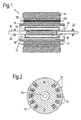
- Figure 1 shows the key components of a typical wound-field superconducting machine 1 having a three-part rotor 10 with inner rotor 13, radiation screen 17 and outer rotor 11. Some parts of the stator are also shown, namely an armature support structure 30, air gap windings 32 and an environmental protection screen 34.
- the inner rotor 13 is driven by a shaft 20 mounted on bearings 22.
- a superconducting field winding 15 surrounds the inner rotor and is cooled by a cooling system which in the embodiment described is a cryogenic system.
- the inner rotor carrying the superconducting winding 15 is fed with cryogen along the axis.
- the inner rotor 13 is surrounded by a region 16 which is maintained under vacuum.
- a cylindrical radiation screen 17 located within the vacuum space surrounds the inner rotor 13. Seals 24 provide a hermetic seal between the outer rotor 11 and the shaft 20.
- the DC current and the cryogenic fluid are supplied to the rotor along the machine's axis.
- the D.C. current supply to the superconductor winding is via conventional means in the form of slip rings which are not shown for the sake of clarity.
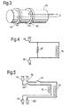
- Figure 2 shows a radial section of the active 2-pole cylindrical region of a typical rotor comparable to the inner rotor 13 of Figure 1 , for a synchronous motor with field coils 15 distributed in slots 18, five pairs in this case.
- DC current is shown coming out of the paper on the left-hand side and into the paper on the right.
- the five coils shown would normally be connected in series.
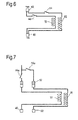
- Figure 3 shows the slip-ring contact arrangement of a typical motor. Brushes, not shown, contact slip rings 40 at all times, one set of brushes per ring.
- the slip rings 40 will generally be mounted on the shaft 20 of the rotor, axially spaced from the main body of the rotor carrying the coil windings. Brushes and slip rings operate together to transfer current between stationary and rotating frames.
- FIG. 4 shows the usual superconducting rotor circuit.
- the two slip rings 40 are connected across the winding 15, with a dump resistor 42 in parallel.
- This resistor 42 absorbs magnetic energy stored in the superconducting winding, so that if the stator excitation system becomes disconnected from the slip rings (i.e. from the rotor) the energy can be dissipated.
- Such a dump resistor is normally present and in the following is assumed present unless otherwise stated.
- FIG. 5 shows a superconducting machine having a backup facility or reversionary mode, for use if the superconducting system fails. It can be seen that, in parallel to the superconducting winding 15 (and a dump resistor if present) there is an additional, non-superconducting or "conventional" winding 55.
- This conventional winding is in close proximity to the superconducting winding - for instance, it can be wound alongside it in the same slots, as shown for example in Figure 2 - but is not connected electrically to the excitation (or any other electrical) system while the superconducting system is operating correctly.
- the brushes which are in the stationary frame, will be moved from one set of slip rings 40 to the other 50 when the fault occurs.
- the switches are shown in the state they would be in before a fault in the superconducting winding or system, i.e. the switch 44 is closed and the switch 54 is open. After the fault, both switches change state.
- the switches could simply be connections between the winding leads and the slip rings that are made and un-made as required.
- the machine which may be a propulsion motor for a vehicle such as a ship, remains available for use in the event of a failure of the main (i.e. superconducting) winding, particularly an electrical open circuit therein or a failure of the cooling system.
- the warming effect of operating using the normally conducting winding reduces the "down time" required before one can effect a repair to the superconducting rotor system.
- switches 44, 54 are close to the cryogenically cooled part of the apparatus (i.e. the inner rotor). This could make the switches difficult to operate.
- switches 44a and 54a are provided in the circuit supplying the brushes 52 which contact the slip-rings 40, 50. In normal superconducting operation, the switch 44a is closed and the switch 54a is open. Thus, as before, the conventional winding 55 is not connected electrically to the excitation system during normal operation.
- the switch 44a When a fault in the superconducting winding 15 occurs, the switch 44a is opened and the switch 54a is closed so that current is supplied through the slip ring 50 to the conventional winding 55, while the superconducting winding 15 is disconnected In this example, the connection and disconnection is made outside the cryogenic region of the rotor 10, in order to facilitate operation.
- one end of the conventional winding is connected to the superconducting field winding 15 at all times; the other end is connected to a separate slip ring 50a, which is connected and disconnected using a switch 54 as above.
- the conventional winding 55 is connected in parallel with the superconducting winding 15 at all times.
- a diode 60 is inserted into the conventional winding circuit so that, when a voltage of the appropriate polarity is applied across the (un-faulted) superconducting winding 15, as occurs during load changes for instance, there is no current flow in the conventional winding.
- the conventional winding 55 may absorb the magnetic field energy in the event of a loss of field current supply, and thus replace the dump resistor commonly used in superconducting machines.
- the conventional winding 55 will offer an alternative path for the current previously flowing in the superconducting winding 15. This effect serves to minimise overheating of and possible damage to the superconducting winding 15. In this case, the conventional winding 55 replaces the dump resistor.
- the conventional winding 55 may carry 10% of the current carried by the superconducting winding in normal operation. As a general approximation, this will provide 30% of the rated speed of a propeller driven vessel.
- the conventional winding 55 has been described and illustrated as a wire separate from that of the superconducting winding 15.
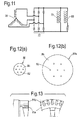
- Superconducting wires or conductors 80 typically consist of filaments 82 of superconducting material embedded within a matrix 84 of non-superconducting metal such as copper, as shown schematically in Figure 12(a) .
- One purpose of the copper matrix 84 is to act as a diversion for the current in the event of a loss of superconducting properties by the superconducting filaments 82.
- the ratio of copper to superconductor in these known superconducting wires is in the range of between 17:1 and 1.35:1 depending on the type of conductor used and the technique used to achieve cryostatic stability.
- the superconducting wire 80a may be designed, as shown in Figure 12(b) , to have a larger quantity of copper 84 in its cross-section than in the conventional superconducting wires described in relation to Figure 12a ..
- the additional copper therefore functions as a parallel non-superconducting winding already built into the system.
- the superconducting filaments 82 would be at a lower density per unit area than in the variant of Figure 12(a) such that the non-superconducting material 84 can be used as a current path for the reversionary mode and steady state operation of the machine in the event of problems with the current-carrying capability of the superconducting filaments 82.
- the ratio of copper to superconductor may be in the range between approximately 20:1 and 200:1.0
- the increased copper area will also provide increased protection against the occurrence of quenches; the better protection is due to the reduced heat generation per unit volume which arises from lower current density in the copper adjacent to a section of quenched superconductor.
- a modified induction motor cage is built into the outer surface of the outer rotor 11; such a cage is easier to access and much closer to ambient temperature than the superconducting field winding 15.
- a part of such a cage is shown in Figure 13 .
- the cage which in ordinary induction machines consists of a cylinder of axial bars 11 b with an end ring 11 a permanently connected at each end, has instead a detachable end ring at one end so as to ensure that induction motor operation does not occur during un-faulted conditions. In the event of a failure of the superconducting field winding then the detachable end ring is connected electrically to the cage so as to make the machine operate as an induction motor.
- the conventional winding need not have the same number of turns as the superconducting winding.
- the conventional winding may be a single bar per slot whereas the superconducting winding will have several turns.
Landscapes
- Engineering & Computer Science (AREA)
- Power Engineering (AREA)
- Superconductive Dynamoelectric Machines (AREA)
Abstract
Description
- Superconducting machines rely upon their superconducting field winding (usually supplied with current through a slip-ring system) remaining superconducting at all times. In the event that the superconducting winding cannot be maintained in the superconducting state (e.g. due to a loss of coolant or damage to the superconductor itself) then the current-carrying capability of the superconductor is greatly reduced. In consequence the machine has little or no electromagnetic torque-generating capability. So, for example, a ship's electric propulsion motor will no longer be able to rotate the propeller shaft. Furthermore, the superconducting system takes typically several days to warm up to ambient temperature, as it needs to do before a repair to the superconductor system can be effected. It is an aim of the invention to address these problems.
- According to a first aspect of the invention there is provided a superconducting electrical machine including a rotor and a stator, the rotor having electrically conductive windings at least one of which is superconducting in normal operation, in which the rotor includes an additional normally-conducting winding which is operable in a first, open-circuit, mode and a second, closed-circuit, mode whereby in the first mode the winding is not excited, and in the second mode the winding current sufficient to operate the machine can be passed through the additional winding if a fault occurs in the superconducting winding.
- Embodiments of the invention provide a conventional (i.e. non-superconducting) winding in parallel with the superconducting winding such that if the superconducting winding cannot carry its rated current then the conventional winding carries some current. This current will probably be less than the superconductor's rated current, but it should be more than the latter's current in the faulted state. This measure gives both (i) "reversionary mode capability" - that is, the capacity for allowing the motor/propeller shaft to continue to turn, so the vessel can continue its journey, albeit at less than rated speed, and (ii) heating of the (inner) rotor, thereby warming the superconductor and cryogenic region of the rotor system more quickly; this reduces the delay before the superconductor or cryogenic system can be repaired.
- The additional winding may be of conventional type, made for instance of copper. It is connected in parallel with the superconducting field winding and has dimensions suitable for providing a propulsive capability comparable to that of the superconductive winding. It may tolerate a current of perhaps 5-10% of the full rated current. When carrying a current it will also warm the rotor relatively quickly towards ambient temperature.
- The additional winding can be wound in the same slots in the rotor as the superconducting winding; one can be wound on top of the other, or they can be wound at the same time for a virtually identical field distribution. In one embodiment the two windings can even be the same wire or cable; superconducting wire generally contains a quantity of normally conducting material such as copper, to be able to absorb the current arising from transient quenches in the superconductor. Thus, to provide the additional winding of the invention in an embodiment of this kind, there is provided a cable containing significantly more copper than the standard cable. Specifically, the additional winding can be in the form of normally-conducting material which surrounds at least one superconducting wire of the superconducting winding. The ratio of the normally conducting material to superconducting material in the cross section can be between approximately 20:1 and 200:1.
- Superconducting machines usually have a so-called dump resistor aboard the rotor, in order to absorb the inductive energy of the superconducting winding in the event that the field current supply is disconnected from the rotor. With some of the variants of this invention no dump resistor is present, its function being performed by the additional parallel winding of the present invention.
- The winding may be an induction cage. The induction cage may comprise axial bars and end rings, the end rings being in electrical contact with the bars in the second mode, and at least one of the end rings being out of electrical contact with the bars in the first mode.
- According to a second aspect of the present invention there is provided a superconducting electrical machine including a rotor and a stator having stator windings, the rotor having an electrically conductive winding which is superconducting in normal operation, in which the rotor includes an induction cage which is operable in a first, open-circuit, mode and a second, closed-circuit, mode whereby current sufficient to operate the machine can flow within the induction cage in the second mode if a fault occurs in the superconducting winding.
- According to a third aspect of the present invention there is provided a method of operating a superconducting electrical machine or motor according to the first or second aspect of the present invention, in which when a fault occurs, current is passed through the additional winding and operation of the machine is continued at reduced power.
- For a better understanding of the invention, embodiments of it will now be described, by way of example, with reference to the accompanying drawings, in which:
- Figure 1
- shows the main features of a typical electric machine with a superconducting rotor;
- Figure 2
- shows a view along the axis of a typical rotor for a synchronous motor;
- Figure 3
- shows the slip-ring concept;
- Figure 4
- shows a conventional superconducting rotor circuit;
- Figure 5
- shows a circuit diagram of a first embodiment of the invention;
- Figure 6
- shows a modification of this embodiment;
- Figure 7
- shows a further variant;
- Figure 8
- shows another variant,
- Figure 9
- shows a modification of the
Figure 8 embodiment; - Figure 10
- shows a yet further variant;
- Figure 11
- shows a brushless embodiment;
- Figure 12
- shows a different embodiment using specially adapted superconducting cable; and
- Figure 13
- shows another embodiment using an induction motor as the backup.
- By way of background, some basic concepts will be set out with reference to
Figures 1-4 .Figure 1 (not to scale) shows the key components of a typical wound-field superconducting machine 1 having a three-part rotor 10 withinner rotor 13,radiation screen 17 andouter rotor 11. Some parts of the stator are also shown, namely anarmature support structure 30,air gap windings 32 and anenvironmental protection screen 34. - The
inner rotor 13 is driven by ashaft 20 mounted onbearings 22. A superconducting field winding 15 surrounds the inner rotor and is cooled by a cooling system which in the embodiment described is a cryogenic system. The inner rotor carrying the superconducting winding 15 is fed with cryogen along the axis. In order to reduce the ingress of heat to the superconductor, known as heat in-leak, theinner rotor 13 is surrounded by aregion 16 which is maintained under vacuum. As a further measure to keep the rotor cold, acylindrical radiation screen 17 located within the vacuum space surrounds theinner rotor 13.Seals 24 provide a hermetic seal between theouter rotor 11 and theshaft 20. - The DC current and the cryogenic fluid are supplied to the rotor along the machine's axis. The D.C. current supply to the superconductor winding is via conventional means in the form of slip rings which are not shown for the sake of clarity.
-
Figure 2 shows a radial section of the active 2-pole cylindrical region of a typical rotor comparable to theinner rotor 13 ofFigure 1 , for a synchronous motor withfield coils 15 distributed inslots 18, five pairs in this case. DC current is shown coming out of the paper on the left-hand side and into the paper on the right. The five coils shown would normally be connected in series. -
Figure 3 shows the slip-ring contact arrangement of a typical motor. Brushes, not shown, contact slip rings 40 at all times, one set of brushes per ring. The slip rings 40 will generally be mounted on theshaft 20 of the rotor, axially spaced from the main body of the rotor carrying the coil windings. Brushes and slip rings operate together to transfer current between stationary and rotating frames. -
Figure 4 shows the usual superconducting rotor circuit. The twoslip rings 40 are connected across the winding 15, with adump resistor 42 in parallel. Thisresistor 42 absorbs magnetic energy stored in the superconducting winding, so that if the stator excitation system becomes disconnected from the slip rings (i.e. from the rotor) the energy can be dissipated. Such a dump resistor is normally present and in the following is assumed present unless otherwise stated. - A first embodiment of the invention is shown in
Figure 5 , which shows a superconducting machine having a backup facility or reversionary mode, for use if the superconducting system fails. It can be seen that, in parallel to the superconducting winding 15 (and a dump resistor if present) there is an additional, non-superconducting or "conventional" winding 55. This conventional winding is in close proximity to the superconducting winding - for instance, it can be wound alongside it in the same slots, as shown for example inFigure 2 - but is not connected electrically to the excitation (or any other electrical) system while the superconducting system is operating correctly. - In the event of a serious or permanent fault with the superconducting winding, it is disconnected from the excitation system and the conventional winding is connected in its place. This connection is made by way of a separate set of slip-rings 50. To transfer the connection, switches 44, 54 are present in the respective leads to the superconducting and normally conducting windings. When a fault is detected, the
superconducting switch 44 is opened and theswitch 54 leading to the normal winding 55 is closed. This switching can be done manually, when the fault is detected, or by way of a control system which monitors operation of the machine and operates the switches automatically on detection of a serious fault. - The brushes, which are in the stationary frame, will be moved from one set of
slip rings 40 to the other 50 when the fault occurs. The switches are shown in the state they would be in before a fault in the superconducting winding or system, i.e. theswitch 44 is closed and theswitch 54 is open. After the fault, both switches change state. The switches could simply be connections between the winding leads and the slip rings that are made and un-made as required. - By this means the machine, which may be a propulsion motor for a vehicle such as a ship, remains available for use in the event of a failure of the main (i.e. superconducting) winding, particularly an electrical open circuit therein or a failure of the cooling system. Moreover, the warming effect of operating using the normally conducting winding reduces the "down time" required before one can effect a repair to the superconducting rotor system.
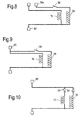
- In the second embodiment, shown in
Figure 6 , there is only one set of slip-rings 40, and thus the brushes do not move from one slip ring set to the other. - In the embodiments of
Figures 5 and6 , theswitches Figure 7 . In the embodiment shown inFigure 7 , switches 44a and 54a are provided in the circuit supplying thebrushes 52 which contact the slip-rings switch 44a is closed and theswitch 54a is open. Thus, as before, the conventional winding 55 is not connected electrically to the excitation system during normal operation. When a fault in the superconducting winding 15 occurs, theswitch 44a is opened and theswitch 54a is closed so that current is supplied through theslip ring 50 to the conventional winding 55, while the superconducting winding 15 is disconnected In this example, the connection and disconnection is made outside the cryogenic region of therotor 10, in order to facilitate operation. In the variants ofFigures 8 and 9 , one end of the conventional winding is connected to the superconducting field winding 15 at all times; the other end is connected to aseparate slip ring 50a, which is connected and disconnected using aswitch 54 as above. In the event of a fault in the superconducting winding 15, the unconnected end of the conventional winding is connected to the field excitation system in parallel with the superconducting winding 15 (Figure 9 ) or using aseparate slip ring 50a, as shown inFigure 8 . The skilled person will appreciate that it is possible to place theswitch 54 shown inFigure 8 at a remote location away from the rotor. - Thus, in the embodiments described above, when current is supplied to the conventional winding it may flow through either (a) the superconducting winding's slip-rings or (b) one or two of the conventional winding's own slip-rings.
- In a third type of embodiment, shown in
Figure 10 , the conventional winding 55 is connected in parallel with the superconducting winding 15 at all times. Instead of a switch, adiode 60 is inserted into the conventional winding circuit so that, when a voltage of the appropriate polarity is applied across the (un-faulted) superconducting winding 15, as occurs during load changes for instance, there is no current flow in the conventional winding. However, the conventional winding 55 may absorb the magnetic field energy in the event of a loss of field current supply, and thus replace the dump resistor commonly used in superconducting machines. - In the event of failure of the superconducting winding 15, the polarity of the direct-current (DC) field current supply or excitation system to the
rotor 10 is reversed in order to drive (steady-state) current through the conventional winding 55. Again, this reversal is carried out either manually or by a monitoring circuit, once the fault is detected.Diode 61 is included for intermittent faults where no current flows through the superconducting winding 15 and when voltage is reversed to drive current through the conventional winding 55. - In the embodiment of
Figure 11 , brushless excitation is used. The conventional winding 55 is connected in parallel with the superconducting winding 15 at all times, because it is difficult to insert a switch. Here a brushless excitation using an exciter rotor winding 70 is applied. This exciter rotor generates a voltage arising from a DC electromagnet on the stator, and supplies it to the superconducting winding 15 via adiode rectifier bridge 72. In this case, as the excitation is changed the conventional winding will take a proportion of the field current. The resistive losses in the conventional winding 55 will cause heating, which leads to a marginally increased cooling requirement.Figure 11 also shows, for illustrative purposes, the equivalent resistance of the conventional winding 55. It will be appreciated that although the current flow in the conventional winding will occur predominantly during changes in excitation, there will likely be a small amount of parasitic AC current in the conventional winding at all times due to the high inductance of the superconducting winding and the voltage ripple created by the rectifier. - If the superconducting winding 15 ceases to be superconductive, for example during a quench or partial quench, the conventional winding 55 will offer an alternative path for the current previously flowing in the superconducting winding 15. This effect serves to minimise overheating of and possible damage to the superconducting winding 15. In this case, the conventional winding 55 replaces the dump resistor.
- By way of example, based on any of the variants described above, the conventional winding 55 may carry 10% of the current carried by the superconducting winding in normal operation. As a general approximation, this will provide 30% of the rated speed of a propeller driven vessel.
- In the embodiments described, the conventional winding 55 has been described and illustrated as a wire separate from that of the superconducting winding 15. Superconducting wires or
conductors 80 typically consist offilaments 82 of superconducting material embedded within amatrix 84 of non-superconducting metal such as copper, as shown schematically inFigure 12(a) . One purpose of thecopper matrix 84 is to act as a diversion for the current in the event of a loss of superconducting properties by thesuperconducting filaments 82. Typically, the ratio of copper to superconductor in these known superconducting wires is in the range of between 17:1 and 1.35:1 depending on the type of conductor used and the technique used to achieve cryostatic stability. - The
superconducting wire 80a may be designed, as shown inFigure 12(b) , to have a larger quantity ofcopper 84 in its cross-section than in the conventional superconducting wires described in relation toFigure 12a .. The additional copper therefore functions as a parallel non-superconducting winding already built into the system. Thus thesuperconducting filaments 82 would be at a lower density per unit area than in the variant ofFigure 12(a) such that thenon-superconducting material 84 can be used as a current path for the reversionary mode and steady state operation of the machine in the event of problems with the current-carrying capability of thesuperconducting filaments 82. In this regard, the ratio of copper to superconductor may be in the range between approximately 20:1 and 200:1.0 - When the superconductor is operating in its un-faulted condition, the increased copper area will also provide increased protection against the occurrence of quenches; the better protection is due to the reduced heat generation per unit volume which arises from lower current density in the copper adjacent to a section of quenched superconductor.
- The machines described previously are synchronous machines. Instead of a separate conventional winding connected in parallel with the superconducting winding, in a further embodiment, a modified induction motor cage is built into the outer surface of the
outer rotor 11; such a cage is easier to access and much closer to ambient temperature than the superconducting field winding 15. A part of such a cage is shown inFigure 13 . The cage, which in ordinary induction machines consists of a cylinder ofaxial bars 11 b with anend ring 11 a permanently connected at each end, has instead a detachable end ring at one end so as to ensure that induction motor operation does not occur during un-faulted conditions. In the event of a failure of the superconducting field winding then the detachable end ring is connected electrically to the cage so as to make the machine operate as an induction motor. - It will be appreciated that, in the above described variants, with the exception of
Figure 12 , the conventional winding need not have the same number of turns as the superconducting winding. In order for the same excitation to be used, the conventional winding may be a single bar per slot whereas the superconducting winding will have several turns. - It will be appreciated that the heat generated by the resistance of the conventional winding 55 when current flows in it will serve to warm the
rotor 10, so reducing the time taken for the rotor to reach a temperature at which it and the superconducting winding 15 can be inspected, dismantled and repaired or replaced. - While the present invention has been described in the context of a superconducting machine, the concept of having an additional parallel winding, i.e. one unconnected during normal operation, to provide a reversionary-mode capability is in principle applicable to the stator and/or rotor of any electrical machine.
Claims (15)
- A superconducting electrical machine (1) including a rotor (10) and a stator (30), the rotor having electrically conductive windings at least one of which (15) is superconducting in normal operation, in which the rotor (10) includes an additional normally-conducting winding (55) which is operable in a first, open-circuit, mode and a second, closed-circuit, mode whereby in the first mode the winding is not excited, and in the second mode the winding current sufficient to operate the machine can be passed through the additional winding if a fault occurs in the superconducting winding.
- A superconducting electrical machine according to claim 1, in which the additional winding (55) is a winding of normally-conducting material running in parallel to the superconducting winding (15).
- A superconducting electrical machine according to claim 2, in which the superconducting winding (15) and the additional winding (55) are two separate windings laid in parallel in the rotor (10).
- A superconducting electrical machine according to claim 3, in which the two windings (15, 55) are supplied with current by respective slip rings (40; 50) on the rotor.
- A superconducting electrical machine according to claim 3, in which the two windings (15, 55) are supplied with current by a common slip ring (40) on the rotor.
- A superconducting electrical machine according to claim 4 or 5, further including switching means (44, 54) for selectively applying current to the superconducting winding (15) when it is functioning normally, and to the additional winding (55) when there is a fault in the superconducting winding.
- A superconducting electrical machine according to claim 5, further including a rectifier (60) preventing current flowing though the additional winding (55) when the superconducting winding (15) is functioning normally, and allowing current to flow through the additional winding when there is a fault in the superconducting winding.
- A superconducting electrical machine according to claim 2, in which the additional winding is in the form of normally-conducting material which surrounds at least one superconducting wire of the superconducting winding (80a), wherein the ratio of normally conducting material to superconducting material in the cross section is between approximately 20:1 and 200:1.
- A superconducting electrical machine according to any one of the preceding claims, further including control means acting to detect a fault and to switch in the normally-conducting winding (55).
- A superconducting electrical machine as claimed in claim 1, wherein the normally conducting winding includes an induction cage (11 a, 11 b).
- A superconducting electrical machine according to claim 10, in which the induction cage (11 a, 11 b) comprises axial bars (11 b) and end rings (11 a), the end rings (11a) being in electrical contact with the bars (11 b) in the second mode, and at least one of the end rings (11a being out of electrical contact with the bars (11 b) in the first mode.
- A superconducting electric motor constituted by a machine according to any preceding claim.
- A watercraft powered by a motor according to claim 12.
- A method of operating a superconducting electrical machine or motor according to any of claims 1 to 12, in which when a fault occurs, current is passed through the additional winding and operation of the machine is continued at reduced power.
- A method according to claim 14, in which the machine or motor is a ship's engine and the operation at reduced power is used to maintain mobility of the ship while warming the cooled rotor
Applications Claiming Priority (1)
| Application Number | Priority Date | Filing Date | Title |
|---|---|---|---|
| GBGB1107888.8A GB201107888D0 (en) | 2011-05-12 | 2011-05-12 | Superconducting electrical machine |
Publications (3)
| Publication Number | Publication Date |
|---|---|
| EP2523322A2 true EP2523322A2 (en) | 2012-11-14 |
| EP2523322A3 EP2523322A3 (en) | 2016-04-06 |
| EP2523322B1 EP2523322B1 (en) | 2017-04-05 |
Family
ID=44243961
Family Applications (1)
| Application Number | Title | Priority Date | Filing Date |
|---|---|---|---|
| EP12166285.2A Not-in-force EP2523322B1 (en) | 2011-05-12 | 2012-05-01 | Superconducting electrical machine |
Country Status (3)
| Country | Link |
|---|---|
| US (1) | US20120286617A1 (en) |
| EP (1) | EP2523322B1 (en) |
| GB (1) | GB201107888D0 (en) |
Cited By (7)
| Publication number | Priority date | Publication date | Assignee | Title |
|---|---|---|---|---|
| WO2015189120A1 (en) * | 2014-06-10 | 2015-12-17 | Siemens Aktiengesellschaft | Electric machine for high speeds |
| WO2015197477A1 (en) * | 2014-06-24 | 2015-12-30 | Siemens Aktiengesellschaft | Electric machine |
| EP3758215A1 (en) * | 2019-06-27 | 2020-12-30 | The Boeing Company | Hybrid wound-rotor motor and generator with induction feed and persistent current |
| US20210203203A1 (en) * | 2018-05-28 | 2021-07-01 | Siemens Aktiengesellschaft | Rotor and machine with a cylindrical carrying body |
| US11056963B2 (en) | 2019-06-27 | 2021-07-06 | The Boeing Company | Hybrid wound-rotor motor and generator with induction feed and persistent current |
| US11069463B2 (en) | 2019-06-27 | 2021-07-20 | The Boeing Company | Hybrid wound-rotor motor and generator with induction feed and persistent current |
| US12374981B2 (en) | 2023-03-30 | 2025-07-29 | The Boeing Company | Superconductor joining and joints |
Families Citing this family (5)
| Publication number | Priority date | Publication date | Assignee | Title |
|---|---|---|---|---|
| JP6262417B2 (en) * | 2012-07-31 | 2018-01-17 | 川崎重工業株式会社 | Magnetic field generator and superconducting rotating machine equipped with the same |
| RU2017146013A (en) * | 2015-07-13 | 2019-08-13 | Херон Энерджи Пте. Лтд | ROTATING ELECTROMAGNETIC DEVICES |
| ES2680793B1 (en) * | 2017-01-24 | 2019-06-19 | Ramos Angel Gabriel Ramos | Configurable coil electric motor |
| US11521771B2 (en) | 2019-04-03 | 2022-12-06 | General Electric Company | System for quench protection of superconducting machines, such as a superconducting wind turbine generator |
| DE102019213232A1 (en) * | 2019-09-02 | 2021-03-04 | Fraunhofer-Gesellschaft zur Förderung der angewandten Forschung e.V. | GROUP OF ROTATING ELECTRIC MACHINERY AND METHOD OF MANUFACTURING ROTATING ELECTRIC MACHINERY |
Family Cites Families (6)
| Publication number | Priority date | Publication date | Assignee | Title |
|---|---|---|---|---|
| US4237507A (en) * | 1978-07-11 | 1980-12-02 | Gosudarstvenny Nauchnoissledovatelsky Energetichesky Institut Imeni G. M. Krzhizhanovskogo | Superconducting magnetic system |
| JPH01204327A (en) * | 1988-02-09 | 1989-08-16 | Mitsubishi Cable Ind Ltd | Circuit breaker |
| US6965183B2 (en) * | 2003-05-27 | 2005-11-15 | Pratt & Whitney Canada Corp. | Architecture for electric machine |
| US8242657B2 (en) * | 2008-03-18 | 2012-08-14 | Kyoto University | Superconductive rotor, superconductive rotating machine and superconductive rotating-machine system |
| GB0814620D0 (en) * | 2008-08-12 | 2008-09-17 | Rolls Royce Plc | An electromechanical arrangement |
| US7843094B2 (en) * | 2009-04-09 | 2010-11-30 | Goodzeit Carl L | Dual armature motor/generator with flux linkage between dual armatures and a superconducting field coil |
-
2011
- 2011-05-12 GB GBGB1107888.8A patent/GB201107888D0/en not_active Ceased
-
2012
- 2012-05-01 US US13/461,274 patent/US20120286617A1/en not_active Abandoned
- 2012-05-01 EP EP12166285.2A patent/EP2523322B1/en not_active Not-in-force
Non-Patent Citations (1)
| Title |
|---|
| None |
Cited By (8)
| Publication number | Priority date | Publication date | Assignee | Title |
|---|---|---|---|---|
| WO2015189120A1 (en) * | 2014-06-10 | 2015-12-17 | Siemens Aktiengesellschaft | Electric machine for high speeds |
| US20170149309A1 (en) * | 2014-06-10 | 2017-05-25 | Siemens Aktiengesellschaft | Electric Machine For High Speeds |
| WO2015197477A1 (en) * | 2014-06-24 | 2015-12-30 | Siemens Aktiengesellschaft | Electric machine |
| US20210203203A1 (en) * | 2018-05-28 | 2021-07-01 | Siemens Aktiengesellschaft | Rotor and machine with a cylindrical carrying body |
| EP3758215A1 (en) * | 2019-06-27 | 2020-12-30 | The Boeing Company | Hybrid wound-rotor motor and generator with induction feed and persistent current |
| US11056963B2 (en) | 2019-06-27 | 2021-07-06 | The Boeing Company | Hybrid wound-rotor motor and generator with induction feed and persistent current |
| US11069463B2 (en) | 2019-06-27 | 2021-07-20 | The Boeing Company | Hybrid wound-rotor motor and generator with induction feed and persistent current |
| US12374981B2 (en) | 2023-03-30 | 2025-07-29 | The Boeing Company | Superconductor joining and joints |
Also Published As
| Publication number | Publication date |
|---|---|
| GB201107888D0 (en) | 2011-06-22 |
| EP2523322A3 (en) | 2016-04-06 |
| US20120286617A1 (en) | 2012-11-15 |
| EP2523322B1 (en) | 2017-04-05 |
Similar Documents
| Publication | Publication Date | Title |
|---|---|---|
| EP2523322B1 (en) | Superconducting electrical machine | |
| KR101722057B1 (en) | Magnetic field generator and superconducting rotating machine provided with same | |
| JP4308308B2 (en) | Superconducting electric motor | |
| JP5397866B2 (en) | Superconducting rotor, superconducting rotating machine and superconducting rotating machine system | |
| US7372676B2 (en) | Motor coil-shorting detecting unit | |
| KR101650260B1 (en) | Superconducting machine and method for the operation thereof | |
| WO2010020392A1 (en) | Generators | |
| Hamilton et al. | Asynchronous magnet–stator topologies in a squirrel-cage superconducting dynamo | |
| Arumugam et al. | A review on turn-turn short circuit fault management | |
| US6359365B1 (en) | Superconducting synchronous machine field winding protection | |
| US9236830B2 (en) | Electrical machine | |
| KR101507306B1 (en) | Field coil protecting apparatus and method of superconducting rotating electric machine | |
| KR101460341B1 (en) | A Protecting Structure and Method of a Field Coil for Superconducting Rotating Machines | |
| AU2012289033B2 (en) | Electrical machine and method for operating it | |
| CN111834985B (en) | Method and apparatus for power system overvoltage protection | |
| US7466046B2 (en) | Methods and apparatus for operating an electric machine | |
| JP2024542070A (en) | Inductively Electrically Excited Synchronous Machine | |
| Nakamura et al. | An induction/synchronous motor with high temperature superconductor/normal conductor hybrid double-cage rotor windings | |
| JP2019030153A (en) | Superconducting rotating machine | |
| WO2025088886A1 (en) | Superconducting coil and superconducting magnet device | |
| Zhang et al. | Construction and testing of a 1000 hp high-temperature superconducting motor | |
| WO2007036430A1 (en) | Method and device for the inductive transfer of energy to super-conductive excitation coils of an electric machine | |
| WO2014005593A2 (en) | A control system for and a method of controlling a superconductive rotating electrical machine |
Legal Events
| Date | Code | Title | Description |
|---|---|---|---|
| PUAI | Public reference made under article 153(3) epc to a published international application that has entered the european phase |
Free format text: ORIGINAL CODE: 0009012 |
|
| AK | Designated contracting states |
Kind code of ref document: A2 Designated state(s): AL AT BE BG CH CY CZ DE DK EE ES FI FR GB GR HR HU IE IS IT LI LT LU LV MC MK MT NL NO PL PT RO RS SE SI SK SM TR |
|
| AX | Request for extension of the european patent |
Extension state: BA ME |
|
| RAP1 | Party data changed (applicant data changed or rights of an application transferred) |
Owner name: ROLLS-ROYCE PLC |
|
| PUAL | Search report despatched |
Free format text: ORIGINAL CODE: 0009013 |
|
| AK | Designated contracting states |
Kind code of ref document: A3 Designated state(s): AL AT BE BG CH CY CZ DE DK EE ES FI FR GB GR HR HU IE IS IT LI LT LU LV MC MK MT NL NO PL PT RO RS SE SI SK SM TR |
|
| AX | Request for extension of the european patent |
Extension state: BA ME |
|
| RIC1 | Information provided on ipc code assigned before grant |
Ipc: H02K 3/02 20060101ALN20160229BHEP Ipc: H02K 17/30 20060101ALN20160229BHEP Ipc: H02K 55/04 20060101AFI20160229BHEP Ipc: H02K 3/28 20060101ALI20160229BHEP Ipc: H02K 13/02 20060101ALN20160229BHEP Ipc: H02K 19/36 20060101ALN20160229BHEP |
|
| 17P | Request for examination filed |
Effective date: 20161003 |
|
| RBV | Designated contracting states (corrected) |
Designated state(s): AL AT BE BG CH CY CZ DE DK EE ES FI FR GB GR HR HU IE IS IT LI LT LU LV MC MK MT NL NO PL PT RO RS SE SI SK SM TR |
|
| GRAP | Despatch of communication of intention to grant a patent |
Free format text: ORIGINAL CODE: EPIDOSNIGR1 |
|
| STAA | Information on the status of an ep patent application or granted ep patent |
Free format text: STATUS: GRANT OF PATENT IS INTENDED |
|
| RIC1 | Information provided on ipc code assigned before grant |
Ipc: H02K 13/02 20060101ALN20170119BHEP Ipc: H02K 17/30 20060101ALN20170119BHEP Ipc: H02K 19/36 20060101ALN20170119BHEP Ipc: H02K 55/04 20060101AFI20170119BHEP Ipc: H02K 3/02 20060101ALN20170119BHEP Ipc: H02K 3/28 20060101ALI20170119BHEP |
|
| GRAS | Grant fee paid |
Free format text: ORIGINAL CODE: EPIDOSNIGR3 |
|
| GRAA | (expected) grant |
Free format text: ORIGINAL CODE: 0009210 |
|
| STAA | Information on the status of an ep patent application or granted ep patent |
Free format text: STATUS: THE PATENT HAS BEEN GRANTED |
|
| INTG | Intention to grant announced |
Effective date: 20170208 |
|
| AK | Designated contracting states |
Kind code of ref document: B1 Designated state(s): AL AT BE BG CH CY CZ DE DK EE ES FI FR GB GR HR HU IE IS IT LI LT LU LV MC MK MT NL NO PL PT RO RS SE SI SK SM TR |
|
| REG | Reference to a national code |
Ref country code: GB Ref legal event code: FG4D |
|
| REG | Reference to a national code |
Ref country code: CH Ref legal event code: EP |
|
| REG | Reference to a national code |
Ref country code: AT Ref legal event code: REF Ref document number: 882664 Country of ref document: AT Kind code of ref document: T Effective date: 20170415 |
|
| REG | Reference to a national code |
Ref country code: IE Ref legal event code: FG4D |
|
| REG | Reference to a national code |
Ref country code: DE Ref legal event code: R096 Ref document number: 602012030675 Country of ref document: DE |
|
| REG | Reference to a national code |
Ref country code: FR Ref legal event code: PLFP Year of fee payment: 6 |
|
| REG | Reference to a national code |
Ref country code: NL Ref legal event code: MP Effective date: 20170405 |
|
| REG | Reference to a national code |
Ref country code: LT Ref legal event code: MG4D |
|
| REG | Reference to a national code |
Ref country code: AT Ref legal event code: MK05 Ref document number: 882664 Country of ref document: AT Kind code of ref document: T Effective date: 20170405 |
|
| PG25 | Lapsed in a contracting state [announced via postgrant information from national office to epo] |
Ref country code: NL Free format text: LAPSE BECAUSE OF FAILURE TO SUBMIT A TRANSLATION OF THE DESCRIPTION OR TO PAY THE FEE WITHIN THE PRESCRIBED TIME-LIMIT Effective date: 20170405 |
|
| PG25 | Lapsed in a contracting state [announced via postgrant information from national office to epo] |
Ref country code: NO Free format text: LAPSE BECAUSE OF FAILURE TO SUBMIT A TRANSLATION OF THE DESCRIPTION OR TO PAY THE FEE WITHIN THE PRESCRIBED TIME-LIMIT Effective date: 20170705 Ref country code: HR Free format text: LAPSE BECAUSE OF FAILURE TO SUBMIT A TRANSLATION OF THE DESCRIPTION OR TO PAY THE FEE WITHIN THE PRESCRIBED TIME-LIMIT Effective date: 20170405 Ref country code: GR Free format text: LAPSE BECAUSE OF FAILURE TO SUBMIT A TRANSLATION OF THE DESCRIPTION OR TO PAY THE FEE WITHIN THE PRESCRIBED TIME-LIMIT Effective date: 20170706 Ref country code: ES Free format text: LAPSE BECAUSE OF FAILURE TO SUBMIT A TRANSLATION OF THE DESCRIPTION OR TO PAY THE FEE WITHIN THE PRESCRIBED TIME-LIMIT Effective date: 20170405 Ref country code: AT Free format text: LAPSE BECAUSE OF FAILURE TO SUBMIT A TRANSLATION OF THE DESCRIPTION OR TO PAY THE FEE WITHIN THE PRESCRIBED TIME-LIMIT Effective date: 20170405 Ref country code: FI Free format text: LAPSE BECAUSE OF FAILURE TO SUBMIT A TRANSLATION OF THE DESCRIPTION OR TO PAY THE FEE WITHIN THE PRESCRIBED TIME-LIMIT Effective date: 20170405 Ref country code: LT Free format text: LAPSE BECAUSE OF FAILURE TO SUBMIT A TRANSLATION OF THE DESCRIPTION OR TO PAY THE FEE WITHIN THE PRESCRIBED TIME-LIMIT Effective date: 20170405 |
|
| PG25 | Lapsed in a contracting state [announced via postgrant information from national office to epo] |
Ref country code: PL Free format text: LAPSE BECAUSE OF FAILURE TO SUBMIT A TRANSLATION OF THE DESCRIPTION OR TO PAY THE FEE WITHIN THE PRESCRIBED TIME-LIMIT Effective date: 20170405 Ref country code: IS Free format text: LAPSE BECAUSE OF FAILURE TO SUBMIT A TRANSLATION OF THE DESCRIPTION OR TO PAY THE FEE WITHIN THE PRESCRIBED TIME-LIMIT Effective date: 20170805 Ref country code: SE Free format text: LAPSE BECAUSE OF FAILURE TO SUBMIT A TRANSLATION OF THE DESCRIPTION OR TO PAY THE FEE WITHIN THE PRESCRIBED TIME-LIMIT Effective date: 20170405 Ref country code: LV Free format text: LAPSE BECAUSE OF FAILURE TO SUBMIT A TRANSLATION OF THE DESCRIPTION OR TO PAY THE FEE WITHIN THE PRESCRIBED TIME-LIMIT Effective date: 20170405 Ref country code: RS Free format text: LAPSE BECAUSE OF FAILURE TO SUBMIT A TRANSLATION OF THE DESCRIPTION OR TO PAY THE FEE WITHIN THE PRESCRIBED TIME-LIMIT Effective date: 20170405 Ref country code: BG Free format text: LAPSE BECAUSE OF FAILURE TO SUBMIT A TRANSLATION OF THE DESCRIPTION OR TO PAY THE FEE WITHIN THE PRESCRIBED TIME-LIMIT Effective date: 20170705 |
|
| REG | Reference to a national code |
Ref country code: CH Ref legal event code: PL |
|
| REG | Reference to a national code |
Ref country code: DE Ref legal event code: R097 Ref document number: 602012030675 Country of ref document: DE |
|
| PG25 | Lapsed in a contracting state [announced via postgrant information from national office to epo] |
Ref country code: SK Free format text: LAPSE BECAUSE OF FAILURE TO SUBMIT A TRANSLATION OF THE DESCRIPTION OR TO PAY THE FEE WITHIN THE PRESCRIBED TIME-LIMIT Effective date: 20170405 Ref country code: EE Free format text: LAPSE BECAUSE OF FAILURE TO SUBMIT A TRANSLATION OF THE DESCRIPTION OR TO PAY THE FEE WITHIN THE PRESCRIBED TIME-LIMIT Effective date: 20170405 Ref country code: DK Free format text: LAPSE BECAUSE OF FAILURE TO SUBMIT A TRANSLATION OF THE DESCRIPTION OR TO PAY THE FEE WITHIN THE PRESCRIBED TIME-LIMIT Effective date: 20170405 Ref country code: CZ Free format text: LAPSE BECAUSE OF FAILURE TO SUBMIT A TRANSLATION OF THE DESCRIPTION OR TO PAY THE FEE WITHIN THE PRESCRIBED TIME-LIMIT Effective date: 20170405 Ref country code: MC Free format text: LAPSE BECAUSE OF FAILURE TO SUBMIT A TRANSLATION OF THE DESCRIPTION OR TO PAY THE FEE WITHIN THE PRESCRIBED TIME-LIMIT Effective date: 20170405 Ref country code: RO Free format text: LAPSE BECAUSE OF FAILURE TO SUBMIT A TRANSLATION OF THE DESCRIPTION OR TO PAY THE FEE WITHIN THE PRESCRIBED TIME-LIMIT Effective date: 20170405 |
|
| PLBE | No opposition filed within time limit |
Free format text: ORIGINAL CODE: 0009261 |
|
| STAA | Information on the status of an ep patent application or granted ep patent |
Free format text: STATUS: NO OPPOSITION FILED WITHIN TIME LIMIT |
|
| REG | Reference to a national code |
Ref country code: IE Ref legal event code: MM4A |
|
| PG25 | Lapsed in a contracting state [announced via postgrant information from national office to epo] |
Ref country code: IT Free format text: LAPSE BECAUSE OF FAILURE TO SUBMIT A TRANSLATION OF THE DESCRIPTION OR TO PAY THE FEE WITHIN THE PRESCRIBED TIME-LIMIT Effective date: 20170405 Ref country code: SM Free format text: LAPSE BECAUSE OF FAILURE TO SUBMIT A TRANSLATION OF THE DESCRIPTION OR TO PAY THE FEE WITHIN THE PRESCRIBED TIME-LIMIT Effective date: 20170405 Ref country code: CH Free format text: LAPSE BECAUSE OF NON-PAYMENT OF DUE FEES Effective date: 20170531 Ref country code: LI Free format text: LAPSE BECAUSE OF NON-PAYMENT OF DUE FEES Effective date: 20170531 |
|
| 26N | No opposition filed |
Effective date: 20180108 |
|
| PG25 | Lapsed in a contracting state [announced via postgrant information from national office to epo] |
Ref country code: LU Free format text: LAPSE BECAUSE OF NON-PAYMENT OF DUE FEES Effective date: 20170501 |
|
| REG | Reference to a national code |
Ref country code: BE Ref legal event code: MM Effective date: 20170531 |
|
| PG25 | Lapsed in a contracting state [announced via postgrant information from national office to epo] |
Ref country code: IE Free format text: LAPSE BECAUSE OF NON-PAYMENT OF DUE FEES Effective date: 20170501 |
|
| REG | Reference to a national code |
Ref country code: FR Ref legal event code: PLFP Year of fee payment: 7 |
|
| PG25 | Lapsed in a contracting state [announced via postgrant information from national office to epo] |
Ref country code: SI Free format text: LAPSE BECAUSE OF FAILURE TO SUBMIT A TRANSLATION OF THE DESCRIPTION OR TO PAY THE FEE WITHIN THE PRESCRIBED TIME-LIMIT Effective date: 20170405 |
|
| PG25 | Lapsed in a contracting state [announced via postgrant information from national office to epo] |
Ref country code: BE Free format text: LAPSE BECAUSE OF NON-PAYMENT OF DUE FEES Effective date: 20170531 |
|
| PG25 | Lapsed in a contracting state [announced via postgrant information from national office to epo] |
Ref country code: MT Free format text: LAPSE BECAUSE OF NON-PAYMENT OF DUE FEES Effective date: 20170501 |
|
| PG25 | Lapsed in a contracting state [announced via postgrant information from national office to epo] |
Ref country code: HU Free format text: LAPSE BECAUSE OF FAILURE TO SUBMIT A TRANSLATION OF THE DESCRIPTION OR TO PAY THE FEE WITHIN THE PRESCRIBED TIME-LIMIT; INVALID AB INITIO Effective date: 20120501 |
|
| PG25 | Lapsed in a contracting state [announced via postgrant information from national office to epo] |
Ref country code: CY Free format text: LAPSE BECAUSE OF NON-PAYMENT OF DUE FEES Effective date: 20170405 |
|
| PG25 | Lapsed in a contracting state [announced via postgrant information from national office to epo] |
Ref country code: MK Free format text: LAPSE BECAUSE OF FAILURE TO SUBMIT A TRANSLATION OF THE DESCRIPTION OR TO PAY THE FEE WITHIN THE PRESCRIBED TIME-LIMIT Effective date: 20170405 |
|
| PG25 | Lapsed in a contracting state [announced via postgrant information from national office to epo] |
Ref country code: TR Free format text: LAPSE BECAUSE OF FAILURE TO SUBMIT A TRANSLATION OF THE DESCRIPTION OR TO PAY THE FEE WITHIN THE PRESCRIBED TIME-LIMIT Effective date: 20170405 |
|
| PG25 | Lapsed in a contracting state [announced via postgrant information from national office to epo] |
Ref country code: PT Free format text: LAPSE BECAUSE OF FAILURE TO SUBMIT A TRANSLATION OF THE DESCRIPTION OR TO PAY THE FEE WITHIN THE PRESCRIBED TIME-LIMIT Effective date: 20170405 |
|
| PG25 | Lapsed in a contracting state [announced via postgrant information from national office to epo] |
Ref country code: AL Free format text: LAPSE BECAUSE OF FAILURE TO SUBMIT A TRANSLATION OF THE DESCRIPTION OR TO PAY THE FEE WITHIN THE PRESCRIBED TIME-LIMIT Effective date: 20170405 |
|
| P01 | Opt-out of the competence of the unified patent court (upc) registered |
Effective date: 20230528 |
|
| PGFP | Annual fee paid to national office [announced via postgrant information from national office to epo] |
Ref country code: FR Payment date: 20230523 Year of fee payment: 12 Ref country code: DE Payment date: 20230530 Year of fee payment: 12 |
|
| PGFP | Annual fee paid to national office [announced via postgrant information from national office to epo] |
Ref country code: GB Payment date: 20230523 Year of fee payment: 12 |
|
| REG | Reference to a national code |
Ref country code: DE Ref legal event code: R119 Ref document number: 602012030675 Country of ref document: DE |
|
| GBPC | Gb: european patent ceased through non-payment of renewal fee |
Effective date: 20240501 |
|
| PG25 | Lapsed in a contracting state [announced via postgrant information from national office to epo] |
Ref country code: DE Free format text: LAPSE BECAUSE OF NON-PAYMENT OF DUE FEES Effective date: 20241203 |
|
| PG25 | Lapsed in a contracting state [announced via postgrant information from national office to epo] |
Ref country code: FR Free format text: LAPSE BECAUSE OF NON-PAYMENT OF DUE FEES Effective date: 20240531 |
|
| PG25 | Lapsed in a contracting state [announced via postgrant information from national office to epo] |
Ref country code: GB Free format text: LAPSE BECAUSE OF NON-PAYMENT OF DUE FEES Effective date: 20240501 |