EP2527226A2 - Railway section delimiting using portable terminal - Google Patents
Railway section delimiting using portable terminal Download PDFInfo
- Publication number
- EP2527226A2 EP2527226A2 EP12161589A EP12161589A EP2527226A2 EP 2527226 A2 EP2527226 A2 EP 2527226A2 EP 12161589 A EP12161589 A EP 12161589A EP 12161589 A EP12161589 A EP 12161589A EP 2527226 A2 EP2527226 A2 EP 2527226A2
- Authority
- EP
- European Patent Office
- Prior art keywords
- portable terminal
- tag
- section
- railway
- possession
- Prior art date
- Legal status (The legal status is an assumption and is not a legal conclusion. Google has not performed a legal analysis and makes no representation as to the accuracy of the status listed.)
- Granted
Links
Images
Classifications
-
- B—PERFORMING OPERATIONS; TRANSPORTING
- B61—RAILWAYS
- B61L—GUIDING RAILWAY TRAFFIC; ENSURING THE SAFETY OF RAILWAY TRAFFIC
- B61L3/00—Devices along the route for controlling devices on the vehicle or train, e.g. to release brake or to operate a warning signal
- B61L3/02—Devices along the route for controlling devices on the vehicle or train, e.g. to release brake or to operate a warning signal at selected places along the route, e.g. intermittent control simultaneous mechanical and electrical control
- B61L3/08—Devices along the route for controlling devices on the vehicle or train, e.g. to release brake or to operate a warning signal at selected places along the route, e.g. intermittent control simultaneous mechanical and electrical control controlling electrically
- B61L3/12—Devices along the route for controlling devices on the vehicle or train, e.g. to release brake or to operate a warning signal at selected places along the route, e.g. intermittent control simultaneous mechanical and electrical control controlling electrically using magnetic or electrostatic induction; using radio waves
- B61L3/125—Devices along the route for controlling devices on the vehicle or train, e.g. to release brake or to operate a warning signal at selected places along the route, e.g. intermittent control simultaneous mechanical and electrical control controlling electrically using magnetic or electrostatic induction; using radio waves using short-range radio transmission
-
- B—PERFORMING OPERATIONS; TRANSPORTING
- B61—RAILWAYS
- B61L—GUIDING RAILWAY TRAFFIC; ENSURING THE SAFETY OF RAILWAY TRAFFIC
- B61L23/00—Control, warning or like safety means along the route or between vehicles or trains
-
- B—PERFORMING OPERATIONS; TRANSPORTING
- B61—RAILWAYS
- B61L—GUIDING RAILWAY TRAFFIC; ENSURING THE SAFETY OF RAILWAY TRAFFIC
- B61L23/00—Control, warning or like safety means along the route or between vehicles or trains
- B61L23/06—Control, warning or like safety means along the route or between vehicles or trains for warning men working on the route
-
- B—PERFORMING OPERATIONS; TRANSPORTING
- B61—RAILWAYS
- B61L—GUIDING RAILWAY TRAFFIC; ENSURING THE SAFETY OF RAILWAY TRAFFIC
- B61L23/00—Control, warning or like safety means along the route or between vehicles or trains
- B61L23/08—Control, warning or like safety means along the route or between vehicles or trains for controlling traffic in one direction only
- B61L23/10—Control, warning or like safety means along the route or between vehicles or trains for controlling traffic in one direction only manually operated, e.g. block arrangements
-
- B—PERFORMING OPERATIONS; TRANSPORTING
- B61—RAILWAYS
- B61L—GUIDING RAILWAY TRAFFIC; ENSURING THE SAFETY OF RAILWAY TRAFFIC
- B61L3/00—Devices along the route for controlling devices on the vehicle or train, e.g. to release brake or to operate a warning signal
- B61L3/02—Devices along the route for controlling devices on the vehicle or train, e.g. to release brake or to operate a warning signal at selected places along the route, e.g. intermittent control simultaneous mechanical and electrical control
- B61L3/08—Devices along the route for controlling devices on the vehicle or train, e.g. to release brake or to operate a warning signal at selected places along the route, e.g. intermittent control simultaneous mechanical and electrical control controlling electrically
- B61L3/12—Devices along the route for controlling devices on the vehicle or train, e.g. to release brake or to operate a warning signal at selected places along the route, e.g. intermittent control simultaneous mechanical and electrical control controlling electrically using magnetic or electrostatic induction; using radio waves
- B61L3/121—Devices along the route for controlling devices on the vehicle or train, e.g. to release brake or to operate a warning signal at selected places along the route, e.g. intermittent control simultaneous mechanical and electrical control controlling electrically using magnetic or electrostatic induction; using radio waves using magnetic induction
-
- B—PERFORMING OPERATIONS; TRANSPORTING
- B61—RAILWAYS
- B61L—GUIDING RAILWAY TRAFFIC; ENSURING THE SAFETY OF RAILWAY TRAFFIC
- B61L3/00—Devices along the route for controlling devices on the vehicle or train, e.g. to release brake or to operate a warning signal
- B61L3/02—Devices along the route for controlling devices on the vehicle or train, e.g. to release brake or to operate a warning signal at selected places along the route, e.g. intermittent control simultaneous mechanical and electrical control
- B61L3/08—Devices along the route for controlling devices on the vehicle or train, e.g. to release brake or to operate a warning signal at selected places along the route, e.g. intermittent control simultaneous mechanical and electrical control controlling electrically
- B61L3/12—Devices along the route for controlling devices on the vehicle or train, e.g. to release brake or to operate a warning signal at selected places along the route, e.g. intermittent control simultaneous mechanical and electrical control controlling electrically using magnetic or electrostatic induction; using radio waves
- B61L3/126—Constructional details
-
- G—PHYSICS
- G01—MEASURING; TESTING
- G01S—RADIO DIRECTION-FINDING; RADIO NAVIGATION; DETERMINING DISTANCE OR VELOCITY BY USE OF RADIO WAVES; LOCATING OR PRESENCE-DETECTING BY USE OF THE REFLECTION OR RERADIATION OF RADIO WAVES; ANALOGOUS ARRANGEMENTS USING OTHER WAVES
- G01S13/00—Systems using the reflection or reradiation of radio waves, e.g. radar systems; Analogous systems using reflection or reradiation of waves whose nature or wavelength is irrelevant or unspecified
- G01S13/74—Systems using reradiation of radio waves, e.g. secondary radar systems; Analogous systems
Definitions
- the present invention relates to a method for delimiting a section of a railway to enable operating restrictions to be performed at the section, a method for managing railway possessions, a method for applying a temporary speed restriction at a section of a railway and a portable, wireless terminal.
- the term “portable” is to be understood to mean “man-portable”, i.e. capable of being picked up and carried readily by an average human being and thus being transported under the human's own power.
- railway availability is highly dependent upon the correct operation of various items of trackside equipment.
- the infrastructure control uses extend to include all trackside infrastructure / equipment including, for example, level crossings, signals, de-railers, staff crossings, point heaters, isolation switches (load breaking and off-load devices), traction power equipment, public address equipment, passenger information display equipment, lifts, escalators, heating ventilation and air conditioning (HVAC) equipment, low voltage power equipment (e.g. UPS), platform screen doors and any other remote-controllable trackside infrastructure / equipment.
- HVAC heating ventilation and air conditioning
- UPS low voltage power equipment
- the term "possession management” relates to the use of a section of railway track. For example, if a train is passing through the track (i.e. during normal operation), the train is in possession of that section of track. Conversely, if maintenance for example is required at a track section, then the possession of the section must be managed to ensure that staff can work safely and that staff and equipment at the section are accounted for.
- PICOP the person in charge of possession. This is an operative who will be at the relevant possession section, controlling local operations.
- HHTs 'hand-held terminals'
- a portable, wireless, terminal to interface to wireless communication tags, for example radio frequency identity (RF-ID) tags, to prove location of possession boundaries and to prove the equipment to be controlled.
- RFID radio frequency identity
- the portable terminal may manage the workflow procedures to control selected infrastructure within the possession boundary without intervention from the signaller.
- the workflow procedures may also be used to overcome the risks of controlling incorrect equipment.
- Barcode readers may be used to 'log-on' staff to the work party by scanning a barcode on their ID card. The staff competencies may also be verified by using this barcode.
- the present invention also provides for the tracking of tools and equipment.
- a method for delimiting a section of a railway to enable operating restrictions to be performed at the section comprising the steps of:
- the portable terminal may comprise remote wireless communication means for enabling communication between the terminal and a remote location.
- the method may comprise the step of denoting an additional section boundary by enabling communication between the portable terminal and a second wireless communication tag, the position of said second tag denoting the additional section boundary.
- the method may comprise the step of providing at least one additional portable terminal comprising wireless tag communication means operable to delimit an additional section boundary by enabling communication between the additional portable terminal and a second wireless communication tag.
- Each wireless communication tag may comprise an RF-ID tag, and the wireless tag communication means of the or each portable terminal may comprise an RF-ID receiver.
- the step of enabling communication between the portable terminal and the wireless communication tag may comprise positioning the portable terminal proximate the tag to enable communication therebetween.
- the ID of the tag may be transmitted to the portable terminal.
- the method may comprise the step of transmitting the received tag ID from the portable terminal to the remote location.
- At least one of said plurality of tags may be mounted on a catenary mast provided along the railway.
- a method for managing railway possessions comprising the steps of: delimiting a section of a railway for possession using a method in accordance with the first aspect.
- the method may further comprise the step of confirming the possession section boundary by sending the ID of the tag at that boundary to a control application at the remote location for confirmation.
- the method may further comprise the step of logging on operatives at the possession section using the portable terminal to record log-on information for each operative.
- the method may comprise the step of verifying the log-on information by sending the log-on information to the control application for verification.
- Identification means may be provided on one or more infrastructure elements of the railway, said identification means being readable by the portable terminal.
- Identification means may be provided on one or more railway equipment items, said identification means being readable by the portable terminal.
- the portable terminal may be provided with location detection means.
- a method for applying a temporary speed restriction at a section of a railway comprising the steps of:
- the method may comprise the step of confirming the section boundary by sending the ID of the tag denoting that boundary to a control application at the remote location.
- a portable, wireless terminal for use in the method according to any of the first three aspects.
- RF-ID tags are preferred, as these are already commonly used in many industries to identify items of plant equipment for the purposes of asset management.
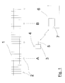
- Fig. 1 shows a length of railway 1.
- a series of catenary masts 2 is located along and adjacent to the railway 1, these being standard with electrified railways.
- Each mast 2 has a respective RF-ID tag mounted thereon.
- Alternative / additional locating methods may include short 'stakes' with the RF-ID tag integrated or attached to such infrastructure.
- RF-ID tags may also / alternatively be integrated into trackside buildings either internally, externally or both.
- RF-ID tags can also be integrated into or attached to infrastructure elements such as level crossings, point machines, de-railers, point heating cubicles, isolation switches (load breaking and off-load devices), traction power equipment, public address equipment, passenger information display equipment, lifts, escalators, heating ventilation and air conditioning (HVAC) equipment, low voltage power equipment (e.g. uninterruptible power supply (UPS)), platform screen doors, axle counter heads, balises, APR transponders, automatic warning system (AWS) / train protection and warning system (TPWS) grids signal heads / masts, traction power substations (including individual equipments within the substations)
- infrastructure elements such as level crossings, point machines, de-railers, point heating cubicles, isolation switches (load breaking and off-load devices), traction power equipment, public address equipment, passenger information display equipment, lifts, escalators, heating ventilation and air conditioning (HVAC) equipment, low voltage power equipment (e.g. uninterruptible power supply (UPS)), platform screen doors, axle
- RF-ID tags and / or barcodes can be applied to line replaceable units (LRUs) such as electronic interlocking cards, local human machine interface (HMI) units / workstations etc.
- LRUs line replaceable units
- HMI human machine interface
- the desired section to be delimited is that lying between boundary points A and B, denoted by the masts (and hence tags) at those points. It should be noted that the boundary points need not be located at adjacent masts.
- a portable terminal 3 is shown, having wireless tag communication means, i.e. RF-ID reading means 4.
- the portable terminal is a wireless device capable of being carried by an operative by hand.
- terminal 3 is battery-powered.
- a remote wireless bi-directional communication means (here schematically shown as a radio transceiver) 5 for enabling wireless communication with a remote location 6, a barcode / QR code scanner or the like (not shown), a processor (not shown), and human interface means (not shown), such as a keypad, display screen, touch screen etc.
- the remote location includes a SIL 2 control centre software application 7 which, as is known in the art, would typically be controlled by a signaller at the remote location 6.
- Application 7 is operable to control a railway interlocking (not shown), and is operable to apply temporary speed restrictions to the railway.
- RF-ID tags are substantially evenly spaced along the rail infrastructure to 'divide' the railway 1 into manageable segments, and as now described facilitates possession management.
- Adaptation will be required to the end user's possession planning system to allocate the new possession location markers, i.e. the tags, to be used by the system.
- a method for possession setup is as follows:
- the secondary location proving is used primarily to warn the PICOP that he is outside of the possession boundary limits delimited as described above. If the PICOP for example leaves the possession limits, a warning alarm is raised on the portable terminal 3 carried by the PICOP. The location information is also transmitted by the terminal 3 to the remotely located control centre software application 7, causing an alarm to be activated at the remote location 6 also. In this way, both the PICOP and signaller are warned that the PICOP is outside of the safe working zone. Similarly, any other team member that carries a portable terminal will also be subject to secondary location proving in this way.
- the secondary location proving may be integrated into the workflow process.
- a workflow process is implemented that will require the PICOP to record the reason for leaving the possession and nominate a person in charge in their absence (if allowed by the railway operational rules).
- An additional / alternative method to identify if the PICOP is outside of the possession boundaries may be enabled by using long range RF-ID tags to mark the boundaries. If long range RF-ID tags are used (not shown), the portable terminal 3 can detect RF-ID tags that are outside of the possession boundary without being held adjacent to the tag, and thus raise the appropriate alarms.
- Possessions are often used to protect workers whilst they maintain or improve the rail infrastructure. In the case of maintenance or improvement works, it is often required that the infrastructure be operated to perform testing and verification of the activities prior to handing back the infrastructure for normal railway operations.
- the portable terminal 3 and RF-ID tags may be used to manage the control of infrastructure elements.
- An RF-ID tag is integrated with or attached to each point machine. Assuming the possession is required to maintain or replace the point machine, the work party will need to verify its correct operation after the work is complete. Current practice is either to operate the points directly from a technician's facility at the interlocking or to request the points to be operated by the signaller remotely.
- a control centre software application 7 and portable terminal 3 workflow is configured to dynamically identify the points within the possession limits delimited as set out above and authorise those for control by the portable terminal 3.
- the points operation workflow becomes available for the PICOP to use.
- the method is as follows:
- the workflow is either paused with advice given to the PICOP to investigate and remedy a fault, or the workflow is cancelled.
- the portable terminal 3 is used either to obtain an individual's identification information, including information on the individual's competencies, directly from an identification unit retained by the individual, for example by: scanning a barcode / QR code or the like, reading a magnetic strip from an ID card, or scanning an individual's own RF-ID tag.
- the identification information is then used to auto-populate possession management records with, for example, the staff member's name, competencies and duty allocation (e.g. protection staff).
- This automated record can then be presented to additional 'sign on' systems as well as be used to confirm or reject a staff member's allocated duty (in the case of competency expiration).
- Automated and electronic recording also facilitates accurate and timely data entry into juridical recording systems should this be required in the future for incident investigation.
- TSRs Temporary Speed Restrictions
- the present invention enables the use of portable terminal 3 to apply TSRs to the railway infrastructure using the RF-ID tags to delimit the start and end boundaries of the required TSR, the tags being spaced as set out above.
- the method of use for temporary speed restriction application is as follows:
- Confirmation from the signaller may be required in some of the process steps above. This is configurable and is largely dependent on individual railway operations' rules.
- portable terminal 3 to 'check in' and 'check out' tools / equipment from use in a possession can be integrated into the possession management workflow described above to ensure that all tools / equipment is accounted for and therefore minimising the risk of a dangerous occurrence.
- the tools / equipment of concern are provided with identification information storing means, for example a barcode / QR code or the like, a magnetic strip, or an RF-ID tag etc, such that this storage means may be interrogated by the terminal 3.
- identification information storing means for example a barcode / QR code or the like, a magnetic strip, or an RF-ID tag etc, such that this storage means may be interrogated by the terminal 3.
Landscapes
- Engineering & Computer Science (AREA)
- Mechanical Engineering (AREA)
- Radar, Positioning & Navigation (AREA)
- Remote Sensing (AREA)
- Computer Networks & Wireless Communication (AREA)
- Physics & Mathematics (AREA)
- General Physics & Mathematics (AREA)
- Train Traffic Observation, Control, And Security (AREA)
- Near-Field Transmission Systems (AREA)
- Management, Administration, Business Operations System, And Electronic Commerce (AREA)
Abstract
providing a plurality of wireless communications tags at intervals along the railway;
providing a portable, wireless terminal comprising wireless tag communication means; and
delimiting a section boundary by enabling communication between the portable terminal and a wireless communication tag, the position of said tag denoting the section boundary.
Description
- The present invention relates to a method for delimiting a section of a railway to enable operating restrictions to be performed at the section, a method for managing railway possessions, a method for applying a temporary speed restriction at a section of a railway and a portable, wireless terminal.
- For the avoidance of doubt, throughout this document, the term "portable" is to be understood to mean "man-portable", i.e. capable of being picked up and carried readily by an average human being and thus being transported under the human's own power.
- Railway availability is highly dependent upon the correct operation of various items of trackside equipment. The following description considers operation of points and point machines in particular, however the infrastructure control uses extend to include all trackside infrastructure / equipment including, for example, level crossings, signals, de-railers, staff crossings, point heaters, isolation switches (load breaking and off-load devices), traction power equipment, public address equipment, passenger information display equipment, lifts, escalators, heating ventilation and air conditioning (HVAC) equipment, low voltage power equipment (e.g. UPS), platform screen doors and any other remote-controllable trackside infrastructure / equipment.
- The term "possession management" relates to the use of a section of railway track. For example, if a train is passing through the track (i.e. during normal operation), the train is in possession of that section of track. Conversely, if maintenance for example is required at a track section, then the possession of the section must be managed to ensure that staff can work safely and that staff and equipment at the section are accounted for.
- The following discussion refers to a "PICOP", the person in charge of possession. This is an operative who will be at the relevant possession section, controlling local operations.
- Currently, wired forms of 'hand-held terminals' (HHTs) are used to facilitate possession management. However, this implementation is limited for the following main reasons:
- Voice command or other manual means must be used to control infrastructure during possessions and is at times cumbersome, especially if repeated operations are required;
- Possessions are often remote, and the enabling of communications to trackside equipment locations / buildings may either increase the possession boundaries or increase the number of staff required to work in the possession;
- Manual methods can become a distraction to the signaller (e.g. control or dispatch centre operator);
- Manual methods to log staff onto the possession work team are used and rely wholly on voice communications;
- Manual methods rely on the PICOP to accurately state their location;
- Manual methods rely on the PICOP following a written procedure, thereby increasing the risk of error that may result in an unsafe occurrence; and
- Manual methods rely on the signaller controlling the infrastructure which the PICOP intends - i.e. there is a high risk of incorrect infrastructure operation that may result in damage to equipment or injury to workers.
- It is an aim of the present invention to provide a method for delimiting a section of a railway to enable operating restrictions to be performed at the section, enabling for example possession management and / or the application of temporary speed restrictions, which overcomes the problems associated with the known methods outlined above.
- This aim is achieved by utilising a portable, wireless, terminal to interface to wireless communication tags, for example radio frequency identity (RF-ID) tags, to prove location of possession boundaries and to prove the equipment to be controlled. In addition to this interface, the portable terminal may manage the workflow procedures to control selected infrastructure within the possession boundary without intervention from the signaller. The workflow procedures may also be used to overcome the risks of controlling incorrect equipment. Barcode readers may be used to 'log-on' staff to the work party by scanning a barcode on their ID card. The staff competencies may also be verified by using this barcode.
- The present invention also provides for the tracking of tools and equipment.
- In accordance with a first aspect of the present invention there is provided a method for delimiting a section of a railway to enable operating restrictions to be performed at the section, comprising the steps of:
- providing a plurality of wireless communications tags at intervals along the railway;
- providing a portable, wireless terminal comprising wireless tag communication means; and
- delimiting a section boundary by enabling communication between the portable terminal and a wireless communication tag, the position of said tag denoting the section boundary.
- The portable terminal may comprise remote wireless communication means for enabling communication between the terminal and a remote location.
- The method may comprise the step of denoting an additional section boundary by enabling communication between the portable terminal and a second wireless communication tag, the position of said second tag denoting the additional section boundary.
- The method may comprise the step of providing at least one additional portable terminal comprising wireless tag communication means operable to delimit an additional section boundary by enabling communication between the additional portable terminal and a second wireless communication tag.
- Each wireless communication tag may comprise an RF-ID tag, and the wireless tag communication means of the or each portable terminal may comprise an RF-ID receiver.
- The step of enabling communication between the portable terminal and the wireless communication tag may comprise positioning the portable terminal proximate the tag to enable communication therebetween.
- During communication between the portable terminal and the tag, the ID of the tag may be transmitted to the portable terminal. In this case, the method may comprise the step of transmitting the received tag ID from the portable terminal to the remote location.
- At least one of said plurality of tags may be mounted on a catenary mast provided along the railway.
- In accordance with a second aspect of the present invention there is provided a method for managing railway possessions comprising the steps of: delimiting a section of a railway for possession using a method in accordance with the first aspect.
- The method may further comprise the step of confirming the possession section boundary by sending the ID of the tag at that boundary to a control application at the remote location for confirmation.
- The method may further comprise the step of logging on operatives at the possession section using the portable terminal to record log-on information for each operative. In this case, the method may comprise the step of verifying the log-on information by sending the log-on information to the control application for verification.
- Identification means may be provided on one or more infrastructure elements of the railway, said identification means being readable by the portable terminal.
- Identification means may be provided on one or more railway equipment items, said identification means being readable by the portable terminal.
- With the method in accordance with either of the first and second aspects, the portable terminal may be provided with location detection means.
- In accordance with a third aspect of the present invention there is provided a method for applying a temporary speed restriction at a section of a railway, comprising the steps of:
- delimiting the section of the railway using as method in accordance with the first aspect; and
- applying the temporary speed restriction to the delimited section.
- The method may comprise the step of confirming the section boundary by sending the ID of the tag denoting that boundary to a control application at the remote location.
- In accordance with a fourth aspect of the present invention there is provided a portable, wireless terminal for use in the method according to any of the first three aspects.
- Key features of the system include:
- Use of tags to identify possession limits during setup, handover and hand back of possessions.
- Use of a secondary location system (GPS / GPRS / alternate RF-ID tag) to warn staff upon leaving the safe working limits.
- Control of infrastructure elements within a possession boundary using a portable terminal.
- Use of a portable terminal for possession management.
- Use of a portable terminal to record protection staff involved with a possession and to record the work party for the possession.
- Use of a portable terminal to verify staff competencies auto populating possession records, providing automated sign on to alternate systems and automated data entry into juridical recording systems.
- Use of predefined automated workflow procedures to manage possessions.
- Use of a portable terminal for application / removal / modification of temporary speed restrictions
- Use of a portable terminal to track tools and equipment used in possessions.
- The use of RF-ID tags is preferred, as these are already commonly used in many industries to identify items of plant equipment for the purposes of asset management.
- The invention will now be described with reference to the accompanying drawings, of which:
-
Fig. 1 schematically shows a railway length. - An indicative general arrangement of RF-ID tags on railway infrastructure is shown in
Figure 1 . -
Fig. 1 shows a length ofrailway 1. A series ofcatenary masts 2 is located along and adjacent to therailway 1, these being standard with electrified railways. Eachmast 2 has a respective RF-ID tag mounted thereon. - Alternative / additional locating methods may include short 'stakes' with the RF-ID tag integrated or attached to such infrastructure.
- RF-ID tags may also / alternatively be integrated into trackside buildings either internally, externally or both.
- RF-ID tags can also be integrated into or attached to infrastructure elements such as level crossings, point machines, de-railers, point heating cubicles, isolation switches (load breaking and off-load devices), traction power equipment, public address equipment, passenger information display equipment, lifts, escalators, heating ventilation and air conditioning (HVAC) equipment, low voltage power equipment (e.g. uninterruptible power supply (UPS)), platform screen doors, axle counter heads, balises, APR transponders, automatic warning system (AWS) / train protection and warning system (TPWS) grids signal heads / masts, traction power substations (including individual equipments within the substations)
- Furthermore, RF-ID tags and / or barcodes can be applied to line replaceable units (LRUs) such as electronic interlocking cards, local human machine interface (HMI) units / workstations etc.
- Here, the desired section to be delimited is that lying between boundary points A and B, denoted by the masts (and hence tags) at those points. It should be noted that the boundary points need not be located at adjacent masts.
- A
portable terminal 3 is shown, having wireless tag communication means, i.e. RF-ID reading means 4. The portable terminal is a wireless device capable of being carried by an operative by hand. To this end,terminal 3 is battery-powered. Included within the terminal, in addition to RF-ID reading means 4, are a remote wireless bi-directional communication means (here schematically shown as a radio transceiver) 5 for enabling wireless communication with aremote location 6, a barcode / QR code scanner or the like (not shown), a processor (not shown), and human interface means (not shown), such as a keypad, display screen, touch screen etc. The remote location includes aSIL 2 controlcentre software application 7 which, as is known in the art, would typically be controlled by a signaller at theremote location 6.Application 7 is operable to control a railway interlocking (not shown), and is operable to apply temporary speed restrictions to the railway. - As described above, RF-ID tags are substantially evenly spaced along the rail infrastructure to 'divide' the
railway 1 into manageable segments, and as now described facilitates possession management. - Adaptation will be required to the end user's possession planning system to allocate the new possession location markers, i.e. the tags, to be used by the system.
- According to an embodiment of the present invention, a method for possession setup is as follows:
- PICOP receives possession orders via standard means (e.g. email, paper etc) as will be known the art.
- The PICOP initiates the possession process by logging into
portable terminal 3 and entering the possession credentials using the human interface means. - The possession credentials are transmitted to
remote location 6 which uses theSIL 2 controlcentre software application 7 for automatic verification. Assuming verification is successful, approval is granted by the application to move to the next workflow step. - The next step in the workflow is to scan the RF-ID tag at the 'beginning' boundary of the possession limit. This is achieved by moving the
portable terminal 3 sufficiently close to the relevant tag to enable communication therebetween, such that theterminal 3 receives the ID information of the tag. This information is transmitted to the remote controlcentre software application 7 and verified automatically. Assuming verification is successful, approval is granted by the application to move to the next workflow step. - The PICOP then scans the RF-ID tag at the 'end' boundary of the possession to obtain that tag's ID information. This information is transmitted to the remote control
centre software application 7 and verified automatically. Assuming verification is successful, approval is granted by the application to move to the next workflow step. - If this is not feasible, for example due to long distances, another person at the 'end' boundary can use their own dedicated portable terminal to scan the 'end' boundary tag. This particular use case (i.e. another person at the 'end' limit) is similar to the single PICOP method, however trackside information is gathered from these two portable terminals rather than a single terminal.
- The next workflow step is to log on the work party who will be working at the possession. To facilitate this, each member of the party is provided with an individual identity information storage device. In a relatively simple embodiment, a barcode or QR code or the like may be used. Alternatively, an RF-ID tag or the like could be employed. The portable terminal must be equipped to read this information to obtain the required log-on information, which is transmitted to the remote control
centre software application 7 and verified automatically. This log-on will also verify that the required protection staff are present and accounted for before granting the possession. Assuming verification is successful, approval is granted by the application to move to the next workflow step. - Once the staff log-on is complete, the control
centre software application 7 issues a 'please confirm' instruction to theportable terminal 3 for the PICOP to accept or reject. If accepted, the controlcentre software application 7 performs the necessary protection controls on the infrastructure, as will be apparent to those skilled in the art. - Once the protection controls are completed, the control
centre software application 7 issues a 'completed' message to theportable terminal 3 advising the PICOP that the possession is in place. - A timer is started both on the
portable terminal 3 and the controlcentre software application 7 that counts down the possession time. Alarms can be configured to alert the PICOP and signaller of the 'T minus' times for possession handover or hand back. - The next workflow steps are highly dependent on individual customer working practices and procedures, and so will not be described further.
- Possession hand back is essentially the reverse of the setup procedure detailed above.
- For possession handover, where a new team takes control of the possession, the current and new PICOPs follow a customer-specific process that is controlled by a separate workflow. Staff identification takes place by the above stated barcode / RF-ID tag method and location proving is achieved by scanning the boundary RF-ID tags.
- In some cases it may be required to use secondary location proving to identify team staff locations.
- The secondary location proving is used primarily to warn the PICOP that he is outside of the possession boundary limits delimited as described above. If the PICOP for example leaves the possession limits, a warning alarm is raised on the
portable terminal 3 carried by the PICOP. The location information is also transmitted by theterminal 3 to the remotely located controlcentre software application 7, causing an alarm to be activated at theremote location 6 also. In this way, both the PICOP and signaller are warned that the PICOP is outside of the safe working zone. Similarly, any other team member that carries a portable terminal will also be subject to secondary location proving in this way. - Various methods may be employed for this purpose, of which the currently preferred are:
- Global positioning system (GPS) location using the
portable terminal 3;
or - General packet radio service (GPRS) location using the
portable terminal 3. - Other wireless locating techniques may however equally be used.
- Whichever method is applied, the secondary location proving may be integrated into the workflow process.
- To prevent alarms, a workflow process is implemented that will require the PICOP to record the reason for leaving the possession and nominate a person in charge in their absence (if allowed by the railway operational rules). An additional / alternative method to identify if the PICOP is outside of the possession boundaries may be enabled by using long range RF-ID tags to mark the boundaries. If long range RF-ID tags are used (not shown), the
portable terminal 3 can detect RF-ID tags that are outside of the possession boundary without being held adjacent to the tag, and thus raise the appropriate alarms. - Possessions are often used to protect workers whilst they maintain or improve the rail infrastructure. In the case of maintenance or improvement works, it is often required that the infrastructure be operated to perform testing and verification of the activities prior to handing back the infrastructure for normal railway operations.
- The
portable terminal 3 and RF-ID tags may be used to manage the control of infrastructure elements. - The following scenario concentrates on the operation of a set of points, however similar methodology can be applied to all controllable infrastructure elements as listed in the "Background" section above.
- An RF-ID tag is integrated with or attached to each point machine. Assuming the possession is required to maintain or replace the point machine, the work party will need to verify its correct operation after the work is complete. Current practice is either to operate the points directly from a technician's facility at the interlocking or to request the points to be operated by the signaller remotely.
- A control
centre software application 7 andportable terminal 3 workflow is configured to dynamically identify the points within the possession limits delimited as set out above and authorise those for control by theportable terminal 3. - Once the possession setup is satisfactorily completed, the points operation workflow becomes available for the PICOP to use. In use, the method is as follows:
- PICOP selects the appropriate workflow (e.g. operate points) on the
portable terminal 3, and this is transmitted toremote location 6. The controlcentre software application 7 verifies that this workflow is available for this possession type and approval is granted to move to the next workflow step, this approval being transmitted to theterminal 3. - The PICOP scans the RF-ID tag of the point machine using the
terminal 3 and transmits this identification information to theremote location 6. The controlcentre software application 7 uses the identification information to verify that the points are within the possession limits and approval is granted to move to the next workflow step, this approval being transmitted to theterminal 3. - The PICOP is presented, by the
terminal 3, with the current state (i.e.
position) of the points as identified by the controlcentre software application 7 and transmitted to the terminal. The PICOP confirms or rejects the points current state on theterminal 3. If confirmed as true, the next workflow step is presented to the PICOP. - The next step in the workflow is for the PICOP to select operation of the points to the opposite state. This request is sent from the
terminal 3 to the controlcentre software application 7, which processes the control as if it was received directly from the signaller's HMI. The controlcentre software application 7 issues a 'please confirm' request to theportable terminal 3 for the PICOP to accept or reject. - If accepted, the acceptance is transmitted to the
application 7, which then issues the infrastructure command to the railway interlocking to move the points. The point status is fed back to the controlcentre software application 7 from the interlocking and then from the control centre software application to theportable terminal 3. - The PICOP then confirms or rejects the status on the
portable terminal 3. - If at any time the PICOP or the control centre software application 'reject' a request, the workflow is either paused with advice given to the PICOP to investigate and remedy a fault, or the workflow is cancelled. These actions are configurable and largely dependent on the individual railway operation's rules.
- Currently, known railway management systems use manual means of staff tracking during possessions is used and this proves to be timely and cumbersome. Often more than one 'sign on' is required to identify the staff and competencies separately in some cases. Most railways utilise ID card systems with photographic identification and a series of codes to readily identify staff and their associated competencies. This at times can be disjointed between trackside and non-trackside competency requirements. This procedure may be simplified and streamlined by the present invention. The
portable terminal 3 is used either to obtain an individual's identification information, including information on the individual's competencies, directly from an identification unit retained by the individual, for example by: scanning a barcode / QR code or the like, reading a magnetic strip from an ID card, or scanning an individual's own RF-ID tag. The identification information is then used to auto-populate possession management records with, for example, the staff member's name, competencies and duty allocation (e.g. protection staff). This automated record can then be presented to additional 'sign on' systems as well as be used to confirm or reject a staff member's allocated duty (in the case of competency expiration). - Automated and electronic recording also facilitates accurate and timely data entry into juridical recording systems should this be required in the future for incident investigation.
- At times, it may be safe to use a railway which is undergoing repair for example, but only in a degraded mode or by restricting the traffic speed through a particular section of the infrastructure.
- In the case of electronic communications-based signalling technologies such as communications-based train control, "distance to go" radio and European rail traffic management system (ERTMS) and track code signalling technologies, current techniques require temporary speed restrictions (TSRs) to be applied from a nominated terminal whereby the user enters the start and end limits of the restriction and the required speed.
- The present invention enables the use of
portable terminal 3 to apply TSRs to the railway infrastructure using the RF-ID tags to delimit the start and end boundaries of the required TSR, the tags being spaced as set out above. - The method of use for temporary speed restriction application is as follows:
- The user (e.g. PICOP) identifies the requirement to implement a TSR.
- The user initiates the TSR process by logging into the
portable terminal 3 and selecting a TSR option, which is then transmitted toSIL 2 controlcentre software application 7. - The TSR option is verified automatically by
application 7, and approval is granted to move to the next workflow step, the approval being sent toterminal 3. - The next step in the workflow is to scan the RF-ID tag at the 'start' of the TSR limit using the
terminal 3 as outlined above. The tag ID is transmitted toapplication 7 for automatic verification by the application and entered into a signalling system TSR manager application / device (a separate, standard component, not shown) by theapplication 7. Approval is then granted to move to the next workflow step, this approval being sent toterminal 3. - The user then scans the RF-ID tag at the 'end' of the TSR limit with
terminal 3. The tag ID is transmitted toapplication 7 for automatic verification by the application and entered into a signalling system TSR manager application / device by theapplication 7. Approval is then granted to move to the next workflow step, this approval being sent toterminal 3. - The user then enters the TSR 'speed' and any other required information (e.g. the line or train type etc) into the
terminal 3. This information is sent toapplication 7 and verified automatically. It is then entered into the signalling system TSR manager application / device by theapplication 7. - The signalling system TSR manager application / device then applies and confirms the TSR to the
application 7. Theapplication 7 then confirms to theportable terminal 3, and thus the user, that the TSR is in place. - Confirmation from the signaller may be required in some of the process steps above. This is configurable and is largely dependent on individual railway operations' rules.
- Many accidents are caused by work teams leaving tools and equipment in unsafe places upon completion of a possession. Accidents can occur when staff either attempt to recover lost or misplaced tools / equipment or when the tools / equipment prevents the safe operation of the rail infrastructure (e.g. a spanner fouling a set of points).
- The use of
portable terminal 3 to 'check in' and 'check out' tools / equipment from use in a possession can be integrated into the possession management workflow described above to ensure that all tools / equipment is accounted for and therefore minimising the risk of a dangerous occurrence. - To enable this integration, the tools / equipment of concern are provided with identification information storing means, for example a barcode / QR code or the like, a magnetic strip, or an RF-ID tag etc, such that this storage means may be interrogated by the
terminal 3. - It is currently not seen as practical to thus identify all tools, so initially at least only larger tools / equipment (e.g. tampers, rail grinders etc) could be barcoded for automated check in and check out. In the case of small hand tools, a 'pick' list is implemented to allow the PICOP to select the tool types and quantities being taken into the possession.
- The above-described embodiments are exemplary only, and various alternatives will be apparent to those skilled in the art.
Claims (15)
- A method for delimiting a section of a railway to enable operating restrictions to be performed at the section, comprising the steps of:providing a plurality of wireless communications tags at intervals along the railway;providing a portable, wireless terminal comprising wireless tag communication means; anddelimiting a section boundary by enabling communication between the portable terminal and a wireless communication tag, the position of said tag denoting the section boundary.
- A method according to claim 1, wherein the portable terminal comprises remote wireless communication means for enabling communication between the terminal and a remote location.
- A method according to either of claims 1 and 2, comprising the step of denoting an additional section boundary by enabling communication between the portable terminal and a second wireless communication tag, the position of said second tag denoting the additional section boundary.
- A method according to any preceding claim, comprising the step of providing at least one additional portable terminal comprising wireless tag communication means operable to delimit an additional section boundary by enabling communication between the additional portable terminal and a second wireless communication tag.
- A method according to any preceding claim, wherein during communication between the portable terminal and the tag, the ID of the tag is transmitted to the portable terminal.
- A method according to claim 5 when dependent on claim 2, wherein the method comprises the step of transmitting the received tag ID from the portable terminal to the remote location.
- A method for managing railway possessions comprising the steps of:delimiting a section of a railway for possession using a method in accordance with any of claims 1 to 6.
- A method according to claim 7, further comprising the step of confirming the possession section boundary by sending the ID of the tag at that boundary to a control application at the remote location for confirmation.
- A method according to either of claims 7 and 8, further comprising the step of logging on operatives at the possession section using the portable terminal to record log-on information for each operative.
- A method according to claim 9, comprising the step of verifying the log-on information by sending the log-on information to the control application for verification.
- A method according to any of claims 7 to 10, wherein identification means are provided on one or more infrastructure elements of the railway, said identification means being readable by the portable terminal.
- A method according to any of claims 7 to 11, wherein identification means are provided on one or more railway equipment items, said identification means being readable by the portable terminal.
- A method for applying a temporary speed restriction at a section of a railway, comprising the steps of:delimiting the section of the railway using as method in accordance with any of claims 1 to 6; andapplying the temporary speed restriction to the delimited section.
- A method according to claim 13, comprising the step of confirming the section boundary by sending the ID of the tag denoting that boundary to a control application at the remote location.
- A portable, wireless terminal for use in the method according to any of claims 1 to 14.
Priority Applications (1)
| Application Number | Priority Date | Filing Date | Title |
|---|---|---|---|
| PL12161589T PL2527226T3 (en) | 2011-05-27 | 2012-03-27 | Railway section delimiting using portable terminal |
Applications Claiming Priority (2)
| Application Number | Priority Date | Filing Date | Title |
|---|---|---|---|
| GBGB1109002.4A GB201109002D0 (en) | 2011-05-27 | 2011-05-27 | Possession management using wireless device |
| GB1116584.2A GB2491214B (en) | 2011-05-27 | 2011-09-27 | Railway section delimiting using portable terminal |
Publications (3)
| Publication Number | Publication Date |
|---|---|
| EP2527226A2 true EP2527226A2 (en) | 2012-11-28 |
| EP2527226A3 EP2527226A3 (en) | 2016-07-20 |
| EP2527226B1 EP2527226B1 (en) | 2018-02-28 |
Family
ID=44310551
Family Applications (1)
| Application Number | Title | Priority Date | Filing Date |
|---|---|---|---|
| EP12161589.2A Active EP2527226B1 (en) | 2011-05-27 | 2012-03-27 | Railway section delimiting using portable terminal |
Country Status (6)
| Country | Link |
|---|---|
| EP (1) | EP2527226B1 (en) |
| DK (1) | DK2527226T3 (en) |
| ES (1) | ES2670936T3 (en) |
| GB (2) | GB201109002D0 (en) |
| NO (1) | NO2527226T3 (en) |
| PL (1) | PL2527226T3 (en) |
Cited By (6)
| Publication number | Priority date | Publication date | Assignee | Title |
|---|---|---|---|---|
| CN104309643A (en) * | 2014-11-18 | 2015-01-28 | 上海自仪泰雷兹交通自动化系统有限公司 | Temporary speed restriction method of PMI (Poste de Manoeuvre Informatise) interlocking system under spot type ATP (Automatic Train Protection) module |
| CN104724142A (en) * | 2015-03-12 | 2015-06-24 | 卡斯柯信号有限公司 | Method for setting temporary speed restriction for train in degraded mode |
| CN105931301A (en) * | 2016-04-14 | 2016-09-07 | 林碧琴 | Rapid train ticket display system |
| DE102015204437A1 (en) | 2015-03-12 | 2016-09-15 | Siemens Aktiengesellschaft | Method and device for determining a signal term for a rail vehicle |
| EP4067201A1 (en) * | 2021-03-31 | 2022-10-05 | Siemens Mobility GmbH | Warning device and method for activating a warning device for a worker |
| GB2595905B (en) * | 2020-06-11 | 2023-04-19 | Siemens Mobility Ltd | Methods and apparatus for electrically isolating a section of railway track or similar |
Family Cites Families (8)
| Publication number | Priority date | Publication date | Assignee | Title |
|---|---|---|---|---|
| GB2248512B (en) * | 1990-10-01 | 1994-04-20 | Marconi Gec Ltd | Vehicle control system |
| EP0793191A1 (en) * | 1996-02-27 | 1997-09-03 | Siemens Schweiz AG (Siemens Suisse SA) (Siemens Svizzera SA) Siemens Switzerland Ltd) | Apparatus for programming an earth-bound station |
| JP3746406B2 (en) * | 1999-08-31 | 2006-02-15 | 財団法人鉄道総合技術研究所 | Closing device |
| JP2006273265A (en) * | 2005-03-30 | 2006-10-12 | Adc Technology Kk | Track inspection worker monitoring device |
| GB2431034A (en) * | 2005-10-06 | 2007-04-11 | Multiclip Co Ltd | Track circuit apparatus for taking possession of a section of track by altering the circuit as an indication of an intention to take possession |
| DE102007006130A1 (en) * | 2007-02-02 | 2008-08-07 | Siemens Ag | Method, mobile operating device and arrangement for transmitting data to a route element of the track-bound traffic |
| DE102008060188A1 (en) * | 2008-11-28 | 2010-06-10 | Siemens Aktiengesellschaft | Method and device for distance measurement |
| CN101537847B (en) * | 2009-04-16 | 2011-06-29 | 北京交通大学 | Implementation method of train operation control system with time speed of 200 to 350 kilometers |
-
2011
- 2011-05-27 GB GBGB1109002.4A patent/GB201109002D0/en not_active Ceased
- 2011-09-27 GB GB1116584.2A patent/GB2491214B/en active Active
-
2012
- 2012-03-27 NO NO12161589A patent/NO2527226T3/no unknown
- 2012-03-27 EP EP12161589.2A patent/EP2527226B1/en active Active
- 2012-03-27 DK DK12161589.2T patent/DK2527226T3/en active
- 2012-03-27 PL PL12161589T patent/PL2527226T3/en unknown
- 2012-03-27 ES ES12161589.2T patent/ES2670936T3/en active Active
Non-Patent Citations (1)
| Title |
|---|
| None |
Cited By (11)
| Publication number | Priority date | Publication date | Assignee | Title |
|---|---|---|---|---|
| CN104309643A (en) * | 2014-11-18 | 2015-01-28 | 上海自仪泰雷兹交通自动化系统有限公司 | Temporary speed restriction method of PMI (Poste de Manoeuvre Informatise) interlocking system under spot type ATP (Automatic Train Protection) module |
| CN104309643B (en) * | 2014-11-18 | 2016-06-15 | 上海自仪泰雷兹交通自动化系统有限公司 | The temporary speed-limiting method of PMI interlocking system under a kind of some formula ATP pattern |
| CN104724142A (en) * | 2015-03-12 | 2015-06-24 | 卡斯柯信号有限公司 | Method for setting temporary speed restriction for train in degraded mode |
| DE102015204437A1 (en) | 2015-03-12 | 2016-09-15 | Siemens Aktiengesellschaft | Method and device for determining a signal term for a rail vehicle |
| WO2016142160A1 (en) | 2015-03-12 | 2016-09-15 | Siemens Aktiengesellschaft | Method and device for determining a signal aspect for a rail vehicle |
| CN107428352A (en) * | 2015-03-12 | 2017-12-01 | 西门子公司 | For the method and apparatus for the signal aspect for determining rail vehicle |
| US10457301B2 (en) | 2015-03-12 | 2019-10-29 | Siemens Mobility GmbH | Method and device for determining a signal aspect for a rail vehicle |
| CN105931301A (en) * | 2016-04-14 | 2016-09-07 | 林碧琴 | Rapid train ticket display system |
| CN105931301B (en) * | 2016-04-14 | 2017-02-22 | 林碧琴 | Rapid train ticket display system |
| GB2595905B (en) * | 2020-06-11 | 2023-04-19 | Siemens Mobility Ltd | Methods and apparatus for electrically isolating a section of railway track or similar |
| EP4067201A1 (en) * | 2021-03-31 | 2022-10-05 | Siemens Mobility GmbH | Warning device and method for activating a warning device for a worker |
Also Published As
| Publication number | Publication date |
|---|---|
| EP2527226B1 (en) | 2018-02-28 |
| PL2527226T3 (en) | 2018-10-31 |
| GB201109002D0 (en) | 2011-07-13 |
| NO2527226T3 (en) | 2018-07-28 |
| GB2491214A (en) | 2012-11-28 |
| DK2527226T3 (en) | 2018-04-30 |
| ES2670936T3 (en) | 2018-06-04 |
| GB2491214B (en) | 2016-03-02 |
| EP2527226A3 (en) | 2016-07-20 |
| GB201116584D0 (en) | 2011-11-09 |
Similar Documents
| Publication | Publication Date | Title |
|---|---|---|
| EP2527226B1 (en) | Railway section delimiting using portable terminal | |
| CN102073891B (en) | System and method for monitoring bank note box in real time | |
| US20130166114A1 (en) | Worker Protection Method | |
| CN105184488A (en) | Railway material management system and management method | |
| CN108995677B (en) | Automatic monitoring and managing method for track | |
| CN113114746B (en) | Intelligent aid decision-making method for work ticket finishing link | |
| CN104076767B (en) | Railway signal equipment overhauling control system and method | |
| US20220402534A1 (en) | Train positioning method and apparatus, system, and computer-readable medium | |
| CN110705348A (en) | Intelligent security fence arrangement method for transformer substation | |
| CN107909155A (en) | A kind of equipment management system and method | |
| CN104850964A (en) | Power production site safety verification device and power production site safety verification method | |
| JP5033774B2 (en) | Railway maintenance work management system | |
| CN105678857B (en) | A kind of intelligent inspection system and method | |
| JP6235261B2 (en) | Patrol work support system, patrol work support method, and patrol work support system program | |
| JP6478218B2 (en) | Closure manual unlocking support system and train position verification device | |
| CN113114747B (en) | An intelligent decision-making method for work ticket permission link | |
| JPH10315972A (en) | Maintenance vehicle position detection device | |
| JP6504941B2 (en) | Train operation management system and train operation management method | |
| CN115470938B (en) | Vehicle maintenance method and system | |
| CN110956242A (en) | High-speed railway tool material and operation management system and method | |
| KR102045412B1 (en) | Work management system, server and method | |
| CN203733152U (en) | Logistics management system based on RFID and video monitoring | |
| JP2007237817A (en) | Management method and system of vehicle for railroad maintenance | |
| CN208278196U (en) | A kind of RFID security identifying system that AGV trolley uses | |
| JP2011141582A (en) | Ticket examining system, ticket examining method |
Legal Events
| Date | Code | Title | Description |
|---|---|---|---|
| PUAI | Public reference made under article 153(3) epc to a published international application that has entered the european phase |
Free format text: ORIGINAL CODE: 0009012 |
|
| AK | Designated contracting states |
Kind code of ref document: A2 Designated state(s): AL AT BE BG CH CY CZ DE DK EE ES FI FR GB GR HR HU IE IS IT LI LT LU LV MC MK MT NL NO PL PT RO RS SE SI SK SM TR |
|
| AX | Request for extension of the european patent |
Extension state: BA ME |
|
| RAP1 | Party data changed (applicant data changed or rights of an application transferred) |
Owner name: SIEMENS RAIL AUTOMATION HOLDINGS LIMITED |
|
| RAP1 | Party data changed (applicant data changed or rights of an application transferred) |
Owner name: SIEMENS RAIL AUTOMATION HOLDINGS LIMITED |
|
| RIC1 | Information provided on ipc code assigned before grant |
Ipc: B61L 23/06 20060101ALI20160412BHEP Ipc: B61L 3/12 20060101AFI20160412BHEP Ipc: B61L 23/10 20060101ALI20160412BHEP Ipc: B61L 23/00 20060101ALI20160412BHEP |
|
| PUAL | Search report despatched |
Free format text: ORIGINAL CODE: 0009013 |
|
| AK | Designated contracting states |
Kind code of ref document: A3 Designated state(s): AL AT BE BG CH CY CZ DE DK EE ES FI FR GB GR HR HU IE IS IT LI LT LU LV MC MK MT NL NO PL PT RO RS SE SI SK SM TR |
|
| AX | Request for extension of the european patent |
Extension state: BA ME |
|
| RIC1 | Information provided on ipc code assigned before grant |
Ipc: B61L 23/10 20060101ALI20160614BHEP Ipc: B61L 23/00 20060101ALI20160614BHEP Ipc: B61L 23/06 20060101ALI20160614BHEP Ipc: B61L 3/12 20060101AFI20160614BHEP |
|
| STAA | Information on the status of an ep patent application or granted ep patent |
Free format text: STATUS: REQUEST FOR EXAMINATION WAS MADE |
|
| 17P | Request for examination filed |
Effective date: 20170120 |
|
| RBV | Designated contracting states (corrected) |
Designated state(s): AL AT BE BG CH CY CZ DE DK EE ES FI FR GB GR HR HU IE IS IT LI LT LU LV MC MK MT NL NO PL PT RO RS SE SI SK SM TR |
|
| GRAP | Despatch of communication of intention to grant a patent |
Free format text: ORIGINAL CODE: EPIDOSNIGR1 |
|
| STAA | Information on the status of an ep patent application or granted ep patent |
Free format text: STATUS: GRANT OF PATENT IS INTENDED |
|
| GRAJ | Information related to disapproval of communication of intention to grant by the applicant or resumption of examination proceedings by the epo deleted |
Free format text: ORIGINAL CODE: EPIDOSDIGR1 |
|
| STAA | Information on the status of an ep patent application or granted ep patent |
Free format text: STATUS: REQUEST FOR EXAMINATION WAS MADE |
|
| GRAP | Despatch of communication of intention to grant a patent |
Free format text: ORIGINAL CODE: EPIDOSNIGR1 |
|
| STAA | Information on the status of an ep patent application or granted ep patent |
Free format text: STATUS: GRANT OF PATENT IS INTENDED |
|
| INTG | Intention to grant announced |
Effective date: 20171005 |
|
| INTC | Intention to grant announced (deleted) | ||
| INTG | Intention to grant announced |
Effective date: 20171024 |
|
| GRAS | Grant fee paid |
Free format text: ORIGINAL CODE: EPIDOSNIGR3 |
|
| GRAA | (expected) grant |
Free format text: ORIGINAL CODE: 0009210 |
|
| STAA | Information on the status of an ep patent application or granted ep patent |
Free format text: STATUS: THE PATENT HAS BEEN GRANTED |
|
| AK | Designated contracting states |
Kind code of ref document: B1 Designated state(s): AL AT BE BG CH CY CZ DE DK EE ES FI FR GB GR HR HU IE IS IT LI LT LU LV MC MK MT NL NO PL PT RO RS SE SI SK SM TR |
|
| REG | Reference to a national code |
Ref country code: GB Ref legal event code: FG4D Ref country code: CH Ref legal event code: EP |
|
| REG | Reference to a national code |
Ref country code: FR Ref legal event code: PLFP Year of fee payment: 7 |
|
| REG | Reference to a national code |
Ref country code: AT Ref legal event code: REF Ref document number: 973769 Country of ref document: AT Kind code of ref document: T Effective date: 20180315 |
|
| REG | Reference to a national code |
Ref country code: IE Ref legal event code: FG4D |
|
| REG | Reference to a national code |
Ref country code: DE Ref legal event code: R096 Ref document number: 602012043269 Country of ref document: DE |
|
| REG | Reference to a national code |
Ref country code: DK Ref legal event code: T3 Effective date: 20180423 |
|
| REG | Reference to a national code |
Ref country code: SE Ref legal event code: TRGR |
|
| REG | Reference to a national code |
Ref country code: NL Ref legal event code: FP |
|
| REG | Reference to a national code |
Ref country code: ES Ref legal event code: FG2A Ref document number: 2670936 Country of ref document: ES Kind code of ref document: T3 Effective date: 20180604 |
|
| REG | Reference to a national code |
Ref country code: NO Ref legal event code: T2 Effective date: 20180228 |
|
| REG | Reference to a national code |
Ref country code: LT Ref legal event code: MG4D |
|
| REG | Reference to a national code |
Ref country code: AT Ref legal event code: MK05 Ref document number: 973769 Country of ref document: AT Kind code of ref document: T Effective date: 20180228 |
|
| PG25 | Lapsed in a contracting state [announced via postgrant information from national office to epo] |
Ref country code: LT Free format text: LAPSE BECAUSE OF FAILURE TO SUBMIT A TRANSLATION OF THE DESCRIPTION OR TO PAY THE FEE WITHIN THE PRESCRIBED TIME-LIMIT Effective date: 20180228 Ref country code: CY Free format text: LAPSE BECAUSE OF FAILURE TO SUBMIT A TRANSLATION OF THE DESCRIPTION OR TO PAY THE FEE WITHIN THE PRESCRIBED TIME-LIMIT Effective date: 20180228 Ref country code: HR Free format text: LAPSE BECAUSE OF FAILURE TO SUBMIT A TRANSLATION OF THE DESCRIPTION OR TO PAY THE FEE WITHIN THE PRESCRIBED TIME-LIMIT Effective date: 20180228 Ref country code: FI Free format text: LAPSE BECAUSE OF FAILURE TO SUBMIT A TRANSLATION OF THE DESCRIPTION OR TO PAY THE FEE WITHIN THE PRESCRIBED TIME-LIMIT Effective date: 20180228 |
|
| PG25 | Lapsed in a contracting state [announced via postgrant information from national office to epo] |
Ref country code: AT Free format text: LAPSE BECAUSE OF FAILURE TO SUBMIT A TRANSLATION OF THE DESCRIPTION OR TO PAY THE FEE WITHIN THE PRESCRIBED TIME-LIMIT Effective date: 20180228 Ref country code: RS Free format text: LAPSE BECAUSE OF FAILURE TO SUBMIT A TRANSLATION OF THE DESCRIPTION OR TO PAY THE FEE WITHIN THE PRESCRIBED TIME-LIMIT Effective date: 20180228 Ref country code: BG Free format text: LAPSE BECAUSE OF FAILURE TO SUBMIT A TRANSLATION OF THE DESCRIPTION OR TO PAY THE FEE WITHIN THE PRESCRIBED TIME-LIMIT Effective date: 20180528 Ref country code: GR Free format text: LAPSE BECAUSE OF FAILURE TO SUBMIT A TRANSLATION OF THE DESCRIPTION OR TO PAY THE FEE WITHIN THE PRESCRIBED TIME-LIMIT Effective date: 20180529 Ref country code: LV Free format text: LAPSE BECAUSE OF FAILURE TO SUBMIT A TRANSLATION OF THE DESCRIPTION OR TO PAY THE FEE WITHIN THE PRESCRIBED TIME-LIMIT Effective date: 20180228 |
|
| PG25 | Lapsed in a contracting state [announced via postgrant information from national office to epo] |
Ref country code: AL Free format text: LAPSE BECAUSE OF FAILURE TO SUBMIT A TRANSLATION OF THE DESCRIPTION OR TO PAY THE FEE WITHIN THE PRESCRIBED TIME-LIMIT Effective date: 20180228 Ref country code: RO Free format text: LAPSE BECAUSE OF FAILURE TO SUBMIT A TRANSLATION OF THE DESCRIPTION OR TO PAY THE FEE WITHIN THE PRESCRIBED TIME-LIMIT Effective date: 20180228 Ref country code: EE Free format text: LAPSE BECAUSE OF FAILURE TO SUBMIT A TRANSLATION OF THE DESCRIPTION OR TO PAY THE FEE WITHIN THE PRESCRIBED TIME-LIMIT Effective date: 20180228 Ref country code: IT Free format text: LAPSE BECAUSE OF FAILURE TO SUBMIT A TRANSLATION OF THE DESCRIPTION OR TO PAY THE FEE WITHIN THE PRESCRIBED TIME-LIMIT Effective date: 20180228 |
|
| REG | Reference to a national code |
Ref country code: CH Ref legal event code: PL |
|
| REG | Reference to a national code |
Ref country code: DE Ref legal event code: R097 Ref document number: 602012043269 Country of ref document: DE |
|
| PG25 | Lapsed in a contracting state [announced via postgrant information from national office to epo] |
Ref country code: SK Free format text: LAPSE BECAUSE OF FAILURE TO SUBMIT A TRANSLATION OF THE DESCRIPTION OR TO PAY THE FEE WITHIN THE PRESCRIBED TIME-LIMIT Effective date: 20180228 Ref country code: CZ Free format text: LAPSE BECAUSE OF FAILURE TO SUBMIT A TRANSLATION OF THE DESCRIPTION OR TO PAY THE FEE WITHIN THE PRESCRIBED TIME-LIMIT Effective date: 20180228 Ref country code: SM Free format text: LAPSE BECAUSE OF FAILURE TO SUBMIT A TRANSLATION OF THE DESCRIPTION OR TO PAY THE FEE WITHIN THE PRESCRIBED TIME-LIMIT Effective date: 20180228 Ref country code: MC Free format text: LAPSE BECAUSE OF FAILURE TO SUBMIT A TRANSLATION OF THE DESCRIPTION OR TO PAY THE FEE WITHIN THE PRESCRIBED TIME-LIMIT Effective date: 20180228 |
|
| REG | Reference to a national code |
Ref country code: BE Ref legal event code: MM Effective date: 20180331 |
|
| REG | Reference to a national code |
Ref country code: IE Ref legal event code: MM4A |
|
| PG25 | Lapsed in a contracting state [announced via postgrant information from national office to epo] |
Ref country code: LU Free format text: LAPSE BECAUSE OF NON-PAYMENT OF DUE FEES Effective date: 20180327 |
|
| PLBE | No opposition filed within time limit |
Free format text: ORIGINAL CODE: 0009261 |
|
| STAA | Information on the status of an ep patent application or granted ep patent |
Free format text: STATUS: NO OPPOSITION FILED WITHIN TIME LIMIT |
|
| GBPC | Gb: european patent ceased through non-payment of renewal fee |
Effective date: 20180528 |
|
| PG25 | Lapsed in a contracting state [announced via postgrant information from national office to epo] |
Ref country code: IE Free format text: LAPSE BECAUSE OF NON-PAYMENT OF DUE FEES Effective date: 20180327 |
|
| 26N | No opposition filed |
Effective date: 20181129 |
|
| PG25 | Lapsed in a contracting state [announced via postgrant information from national office to epo] |
Ref country code: SI Free format text: LAPSE BECAUSE OF FAILURE TO SUBMIT A TRANSLATION OF THE DESCRIPTION OR TO PAY THE FEE WITHIN THE PRESCRIBED TIME-LIMIT Effective date: 20180228 Ref country code: CH Free format text: LAPSE BECAUSE OF NON-PAYMENT OF DUE FEES Effective date: 20180331 Ref country code: LI Free format text: LAPSE BECAUSE OF NON-PAYMENT OF DUE FEES Effective date: 20180331 Ref country code: BE Free format text: LAPSE BECAUSE OF NON-PAYMENT OF DUE FEES Effective date: 20180331 |
|
| PG25 | Lapsed in a contracting state [announced via postgrant information from national office to epo] |
Ref country code: GB Free format text: LAPSE BECAUSE OF NON-PAYMENT OF DUE FEES Effective date: 20180528 |
|
| REG | Reference to a national code |
Ref country code: DE Ref legal event code: R082 Ref document number: 602012043269 Country of ref document: DE Representative=s name: MAIER, DANIEL OLIVER, DIPL.-ING. UNIV., DE Ref country code: DE Ref legal event code: R081 Ref document number: 602012043269 Country of ref document: DE Owner name: SIEMENS MOBILITY LIMITED, FRIMLEY, GB Free format text: FORMER OWNER: SIEMENS RAIL AUTOMATION HOLDINGS LTD., FRIMLEY, CAMBERLEY, GB Ref country code: DE Ref legal event code: R082 Ref document number: 602012043269 Country of ref document: DE Representative=s name: DEFFNER, ROLF, DR., DE Ref country code: DE Ref legal event code: R081 Ref document number: 602012043269 Country of ref document: DE Owner name: SIEMENS MOBILITY LIMITED, GB Free format text: FORMER OWNER: SIEMENS RAIL AUTOMATION HOLDINGS LTD., FRIMLEY, CAMBERLEY, GB |
|
| REG | Reference to a national code |
Ref country code: NL Ref legal event code: HC Owner name: SIEMENS MOBILITY LIMITED; GB Free format text: DETAILS ASSIGNMENT: CHANGE OF OWNER(S), CHANGE OF OWNER(S) NAME; FORMER OWNER NAME: SIEMENS RAIL AUTOMATION HOLDINGS LIMITED Effective date: 20191119 |
|
| REG | Reference to a national code |
Ref country code: DE Ref legal event code: R082 Ref document number: 602012043269 Country of ref document: DE Representative=s name: DEFFNER, ROLF, DR., DE |
|
| REG | Reference to a national code |
Ref country code: NO Ref legal event code: CHAD Owner name: SIEMENS MOBILITY LIMITED, GB |
|
| REG | Reference to a national code |
Ref country code: ES Ref legal event code: PC2A Owner name: SIEMENS MOBILITY LIMITED Effective date: 20191212 |
|
| PG25 | Lapsed in a contracting state [announced via postgrant information from national office to epo] |
Ref country code: MT Free format text: LAPSE BECAUSE OF NON-PAYMENT OF DUE FEES Effective date: 20180327 |
|
| PG25 | Lapsed in a contracting state [announced via postgrant information from national office to epo] |
Ref country code: TR Free format text: LAPSE BECAUSE OF FAILURE TO SUBMIT A TRANSLATION OF THE DESCRIPTION OR TO PAY THE FEE WITHIN THE PRESCRIBED TIME-LIMIT Effective date: 20180228 |
|
| PG25 | Lapsed in a contracting state [announced via postgrant information from national office to epo] |
Ref country code: HU Free format text: LAPSE BECAUSE OF FAILURE TO SUBMIT A TRANSLATION OF THE DESCRIPTION OR TO PAY THE FEE WITHIN THE PRESCRIBED TIME-LIMIT; INVALID AB INITIO Effective date: 20120327 Ref country code: PT Free format text: LAPSE BECAUSE OF FAILURE TO SUBMIT A TRANSLATION OF THE DESCRIPTION OR TO PAY THE FEE WITHIN THE PRESCRIBED TIME-LIMIT Effective date: 20180228 |
|
| PG25 | Lapsed in a contracting state [announced via postgrant information from national office to epo] |
Ref country code: MK Free format text: LAPSE BECAUSE OF NON-PAYMENT OF DUE FEES Effective date: 20180228 |
|
| PG25 | Lapsed in a contracting state [announced via postgrant information from national office to epo] |
Ref country code: IS Free format text: LAPSE BECAUSE OF FAILURE TO SUBMIT A TRANSLATION OF THE DESCRIPTION OR TO PAY THE FEE WITHIN THE PRESCRIBED TIME-LIMIT Effective date: 20180628 |
|
| REG | Reference to a national code |
Ref country code: DE Ref legal event code: R082 Ref document number: 602012043269 Country of ref document: DE Representative=s name: DEFFNER, ROLF, DR., DE Ref country code: DE Ref legal event code: R081 Ref document number: 602012043269 Country of ref document: DE Owner name: SIEMENS MOBILITY LIMITED, GB Free format text: FORMER OWNER: SIEMENS MOBILITY LIMITED, FRIMLEY, SURREY, GB |
|
| PGFP | Annual fee paid to national office [announced via postgrant information from national office to epo] |
Ref country code: DE Payment date: 20250520 Year of fee payment: 14 |
|
| PGFP | Annual fee paid to national office [announced via postgrant information from national office to epo] |
Ref country code: ES Payment date: 20250620 Year of fee payment: 14 |
|
| PGFP | Annual fee paid to national office [announced via postgrant information from national office to epo] |
Ref country code: SE Payment date: 20260305 Year of fee payment: 15 |
|
| PGFP | Annual fee paid to national office [announced via postgrant information from national office to epo] |
Ref country code: NO Payment date: 20260311 Year of fee payment: 15 Ref country code: DK Payment date: 20260324 Year of fee payment: 15 |
|
| PGFP | Annual fee paid to national office [announced via postgrant information from national office to epo] |
Ref country code: NL Payment date: 20260309 Year of fee payment: 15 |
|
| PGFP | Annual fee paid to national office [announced via postgrant information from national office to epo] |
Ref country code: FR Payment date: 20260316 Year of fee payment: 15 |
|
| PGFP | Annual fee paid to national office [announced via postgrant information from national office to epo] |
Ref country code: PL Payment date: 20260319 Year of fee payment: 15 |