EP2531286B1 - Procédé pour la synthèse de méthanol - Google Patents
Procédé pour la synthèse de méthanol Download PDFInfo
- Publication number
- EP2531286B1 EP2531286B1 EP12710531.0A EP12710531A EP2531286B1 EP 2531286 B1 EP2531286 B1 EP 2531286B1 EP 12710531 A EP12710531 A EP 12710531A EP 2531286 B1 EP2531286 B1 EP 2531286B1
- Authority
- EP
- European Patent Office
- Prior art keywords
- catalyst
- process according
- container
- reactor
- skirt
- Prior art date
- Legal status (The legal status is an assumption and is not a legal conclusion. Google has not performed a legal analysis and makes no representation as to the accuracy of the status listed.)
- Not-in-force
Links
Images


Classifications
-
- B—PERFORMING OPERATIONS; TRANSPORTING
- B01—PHYSICAL OR CHEMICAL PROCESSES OR APPARATUS IN GENERAL
- B01J—CHEMICAL OR PHYSICAL PROCESSES, e.g. CATALYSIS OR COLLOID CHEMISTRY; THEIR RELEVANT APPARATUS
- B01J8/00—Chemical or physical processes in general, conducted in the presence of fluids and solid particles; Apparatus for such processes
- B01J8/02—Chemical or physical processes in general, conducted in the presence of fluids and solid particles; Apparatus for such processes with stationary particles, e.g. in fixed beds
- B01J8/04—Chemical or physical processes in general, conducted in the presence of fluids and solid particles; Apparatus for such processes with stationary particles, e.g. in fixed beds the fluid passing successively through two or more beds
-
- C—CHEMISTRY; METALLURGY
- C07—ORGANIC CHEMISTRY
- C07C—ACYCLIC OR CARBOCYCLIC COMPOUNDS
- C07C29/00—Preparation of compounds having hydroxy or O-metal groups bound to a carbon atom not belonging to a six-membered aromatic ring
- C07C29/15—Preparation of compounds having hydroxy or O-metal groups bound to a carbon atom not belonging to a six-membered aromatic ring by reduction of oxides of carbon exclusively
- C07C29/151—Preparation of compounds having hydroxy or O-metal groups bound to a carbon atom not belonging to a six-membered aromatic ring by reduction of oxides of carbon exclusively with hydrogen or hydrogen-containing gases
- C07C29/152—Preparation of compounds having hydroxy or O-metal groups bound to a carbon atom not belonging to a six-membered aromatic ring by reduction of oxides of carbon exclusively with hydrogen or hydrogen-containing gases characterised by the reactor used
-
- B—PERFORMING OPERATIONS; TRANSPORTING
- B01—PHYSICAL OR CHEMICAL PROCESSES OR APPARATUS IN GENERAL
- B01J—CHEMICAL OR PHYSICAL PROCESSES, e.g. CATALYSIS OR COLLOID CHEMISTRY; THEIR RELEVANT APPARATUS
- B01J19/00—Chemical, physical or physico-chemical processes in general; Their relevant apparatus
- B01J19/24—Stationary reactors without moving elements inside
- B01J19/248—Reactors comprising multiple separated flow channels
- B01J19/2485—Monolithic reactors
-
- B—PERFORMING OPERATIONS; TRANSPORTING
- B01—PHYSICAL OR CHEMICAL PROCESSES OR APPARATUS IN GENERAL
- B01J—CHEMICAL OR PHYSICAL PROCESSES, e.g. CATALYSIS OR COLLOID CHEMISTRY; THEIR RELEVANT APPARATUS
- B01J35/00—Catalysts, in general, characterised by their form or physical properties
- B01J35/50—Catalysts, in general, characterised by their form or physical properties characterised by their shape or configuration
- B01J35/56—Foraminous structures having flow-through passages or channels, e.g. grids or three-dimensional [3D] monoliths
-
- B—PERFORMING OPERATIONS; TRANSPORTING
- B01—PHYSICAL OR CHEMICAL PROCESSES OR APPARATUS IN GENERAL
- B01J—CHEMICAL OR PHYSICAL PROCESSES, e.g. CATALYSIS OR COLLOID CHEMISTRY; THEIR RELEVANT APPARATUS
- B01J8/00—Chemical or physical processes in general, conducted in the presence of fluids and solid particles; Apparatus for such processes
- B01J8/02—Chemical or physical processes in general, conducted in the presence of fluids and solid particles; Apparatus for such processes with stationary particles, e.g. in fixed beds
- B01J8/04—Chemical or physical processes in general, conducted in the presence of fluids and solid particles; Apparatus for such processes with stationary particles, e.g. in fixed beds the fluid passing successively through two or more beds
- B01J8/0403—Chemical or physical processes in general, conducted in the presence of fluids and solid particles; Apparatus for such processes with stationary particles, e.g. in fixed beds the fluid passing successively through two or more beds the fluid flow within the beds being predominantly horizontal
- B01J8/0407—Chemical or physical processes in general, conducted in the presence of fluids and solid particles; Apparatus for such processes with stationary particles, e.g. in fixed beds the fluid passing successively through two or more beds the fluid flow within the beds being predominantly horizontal through two or more cylindrical annular shaped beds
- B01J8/0415—Chemical or physical processes in general, conducted in the presence of fluids and solid particles; Apparatus for such processes with stationary particles, e.g. in fixed beds the fluid passing successively through two or more beds the fluid flow within the beds being predominantly horizontal through two or more cylindrical annular shaped beds the beds being superimposed one above the other
-
- B—PERFORMING OPERATIONS; TRANSPORTING
- B01—PHYSICAL OR CHEMICAL PROCESSES OR APPARATUS IN GENERAL
- B01J—CHEMICAL OR PHYSICAL PROCESSES, e.g. CATALYSIS OR COLLOID CHEMISTRY; THEIR RELEVANT APPARATUS
- B01J8/00—Chemical or physical processes in general, conducted in the presence of fluids and solid particles; Apparatus for such processes
- B01J8/02—Chemical or physical processes in general, conducted in the presence of fluids and solid particles; Apparatus for such processes with stationary particles, e.g. in fixed beds
- B01J8/04—Chemical or physical processes in general, conducted in the presence of fluids and solid particles; Apparatus for such processes with stationary particles, e.g. in fixed beds the fluid passing successively through two or more beds
- B01J8/0496—Heating or cooling the reactor
-
- B—PERFORMING OPERATIONS; TRANSPORTING
- B01—PHYSICAL OR CHEMICAL PROCESSES OR APPARATUS IN GENERAL
- B01J—CHEMICAL OR PHYSICAL PROCESSES, e.g. CATALYSIS OR COLLOID CHEMISTRY; THEIR RELEVANT APPARATUS
- B01J8/00—Chemical or physical processes in general, conducted in the presence of fluids and solid particles; Apparatus for such processes
- B01J8/02—Chemical or physical processes in general, conducted in the presence of fluids and solid particles; Apparatus for such processes with stationary particles, e.g. in fixed beds
- B01J8/06—Chemical or physical processes in general, conducted in the presence of fluids and solid particles; Apparatus for such processes with stationary particles, e.g. in fixed beds in tube reactors; the solid particles being arranged in tubes
- B01J8/067—Heating or cooling the reactor
-
- C—CHEMISTRY; METALLURGY
- C07—ORGANIC CHEMISTRY
- C07C—ACYCLIC OR CARBOCYCLIC COMPOUNDS
- C07C31/00—Saturated compounds having hydroxy or O-metal groups bound to acyclic carbon atoms
- C07C31/02—Monohydroxylic acyclic alcohols
- C07C31/04—Methanol
-
- B—PERFORMING OPERATIONS; TRANSPORTING
- B01—PHYSICAL OR CHEMICAL PROCESSES OR APPARATUS IN GENERAL
- B01J—CHEMICAL OR PHYSICAL PROCESSES, e.g. CATALYSIS OR COLLOID CHEMISTRY; THEIR RELEVANT APPARATUS
- B01J2208/00—Processes carried out in the presence of solid particles; Reactors therefor
- B01J2208/00796—Details of the reactor or of the particulate material
- B01J2208/00805—Details of the particulate material
- B01J2208/00814—Details of the particulate material the particulate material being provides in prefilled containers
-
- B—PERFORMING OPERATIONS; TRANSPORTING
- B01—PHYSICAL OR CHEMICAL PROCESSES OR APPARATUS IN GENERAL
- B01J—CHEMICAL OR PHYSICAL PROCESSES, e.g. CATALYSIS OR COLLOID CHEMISTRY; THEIR RELEVANT APPARATUS
- B01J2219/00—Chemical, physical or physico-chemical processes in general; Their relevant apparatus
- B01J2219/00002—Chemical plants
- B01J2219/00027—Process aspects
- B01J2219/00038—Processes in parallel
-
- B—PERFORMING OPERATIONS; TRANSPORTING
- B01—PHYSICAL OR CHEMICAL PROCESSES OR APPARATUS IN GENERAL
- B01J—CHEMICAL OR PHYSICAL PROCESSES, e.g. CATALYSIS OR COLLOID CHEMISTRY; THEIR RELEVANT APPARATUS
- B01J2219/00—Chemical, physical or physico-chemical processes in general; Their relevant apparatus
- B01J2219/00002—Chemical plants
- B01J2219/00027—Process aspects
- B01J2219/0004—Processes in series
-
- Y—GENERAL TAGGING OF NEW TECHNOLOGICAL DEVELOPMENTS; GENERAL TAGGING OF CROSS-SECTIONAL TECHNOLOGIES SPANNING OVER SEVERAL SECTIONS OF THE IPC; TECHNICAL SUBJECTS COVERED BY FORMER USPC CROSS-REFERENCE ART COLLECTIONS [XRACs] AND DIGESTS
- Y02—TECHNOLOGIES OR APPLICATIONS FOR MITIGATION OR ADAPTATION AGAINST CLIMATE CHANGE
- Y02P—CLIMATE CHANGE MITIGATION TECHNOLOGIES IN THE PRODUCTION OR PROCESSING OF GOODS
- Y02P20/00—Technologies relating to chemical industry
- Y02P20/50—Improvements relating to the production of bulk chemicals
- Y02P20/52—Improvements relating to the production of bulk chemicals using catalysts, e.g. selective catalysts
Definitions
- the present invention relates to a process for the conversion of carbon monoxide, carbon dioxide and hydrogen, collectively known as synthesis gas to liquid products in the presence of a methanol synthesis catalyst.
- the synthesis gas may be derived from a number of sources such as reformed natural gas or by the gasification of coal or biomass.
- One approach to handling the heat evolved is to carry out the reaction in a fixed bed reactor.
- An example of a suitable reactor design can be found in GB 1364357 .
- catalyst pellets are loaded inside tubes of an axial reactor. Cooling medium, such as vaporising water, is supplied around the tubes. Reactant gases are then passed through the tubes where they contact the catalyst and the methanol forming reaction takes place. The heat evolved is transferred through the tube wall to the surrounding cooling medium.
- heat transfer resistance from the centre of the tube to the wall can be significant and therefore, in view of the need to control the heat within the tube, the size of the tubes is limited to allow the heat to pass readily from the centre of the tubes to the walls where heat exchange occurs.
- the tubes have a diameter of less than about 40 mm to ensure the required level of heat transfer and to prevent the catalyst located towards the centre of the tube overheating which will increase the production of by-products. This represents not only a loss in conversion to the desired product but also leads to the need to separate the by-products which increases costs.
- the small size of the tubes contributes to the high cost of construction of these reactors.
- a process for the conversion of synthesis gas to methanol by contacting a gaseous stream comprising synthesis gas with a particulate catalyst said process being carried out in a tubular reactor having an inlet and an outlet, said outlet being located downstream of the inlet, said reactor comprising one or more tubes having located therein one or more carriers for said particulate catalyst and cooling medium in contact with said at least one tube; wherein said catalyst carrier comprises:
- the catalyst carrier is described in detail in PCT/GB2010/001931 filed on 19th October 2010 which is incorporated herein by reference.
- the catalyst container will generally be sized such that it is of a smaller dimension than the internal dimension of the reactor tube into which it is placed.
- the seal is sized such that it interacts with the inner wall of the reactor tube when the catalyst carrier of the present invention is in position within the tube.
- the seal need not be perfect provided it is sufficiently effective to cause the majority of the flowing gas to pass through the carrier.
- a plurality of catalyst carriers will be stacked within the reactor tube.
- the reactants/products flow downwardly between the outer surface of the skirt of a first carrier and the inner surface of the reactor tube until they contact the upper surface and seal of a second carrier and are directed downwardly into the tube of the second carrier defined by the perforated inner wall of its annular container. The flow path described above is then repeated.
- the catalyst carrier may be formed of any suitable material. Such material will generally be selected to withstand the operating conditions of the reactor. Generally, the catalyst carrier will be fabricated from carbon steel, aluminium, stainless steel, other alloys or any material able to withstand the reaction conditions.
- the wall of the annular container can be of any suitable thickness. Suitable thickness will be of the order of about 0.1 mm to about 1.0 mm, preferably of the order of about 0.3 mm to about 0.5 mm.
- the size of the perforations in the inner and outer walls of the annular container will be selected such as to allow uniform flow of reactant(s) and product(s) through the catalyst while maintaining the catalyst within the container. It will therefore be understood that their size will depend on the size of the catalyst particles being used.
- the perforations may be sized such that they are larger but have a filter mesh covering the perforations to ensure catalyst is maintained within the annular container. This enables larger perforations to be used which will facilitate the free movement of reactants without a significant loss of pressure.
- perforations may be of any suitable configuration. Indeed where a wall is described as perforated all that is required is that there is means to allow the reactants and products to pass through the walls. These may be small apertures of any configuration, they may be slots, they may be formed by a wire screen or by any other means of creating a porous or permeable surface.
- top surface closing the annular container will generally be located at the upper edge of the or each wall of the annular container, it may be desirable to locate the top surface below the upper edge such that a portion of the upper edge of the outer wall forms a lip.
- bottom surface may be located at the lower edge of the, or each, wall of the annular container or may be desirable to locate the bottom surface such that it is above the bottom edge of the wall of the annular container such that the wall forms a lip.
- the bottom surface of the annulus and the surface closing the bottom of the tube may be formed as a single unit or they may be two separate pieces connected together.
- the two surfaces may be coplanar but in a preferred arrangement, they are in different planes.
- the surface closing the bottom of the tube is in a lower plane than the bottom surface of the annular container. This serves to assist in the location of one carrier on to a carrier arranged below it when a plurality of containers are to be used. It will be understood that in an alternative arrangement, the surface closing the bottom of the tube may be in a higher plane that the bottom surface of the annular container.
- the bottom surface will generally be solid, it may include one or more drain holes. Where one or more drain holes are present, they may be covered by a filter mesh. Similarly a drain hole, optionally covered with a filter mesh may be present in the surface closing the bottom of the tube. Where the carrier is to be used in a non-vertical orientation, the drain hole, where present will be located in an alternative position i.e. one that is the lowest point in the carrier when in use.
- One or more spacer means may extend downwardly from the bottom surface of the annular container.
- The, or each, spacer means may be formed as separate components or they may be formed by depressions in the bottom surface. Where these spacer means are present they assist in providing a clear path for the reactants and products flowing between the bottom surface of the first carrier and the top surface of a second lower carrier in use.
- the spacer may be of the order of about 4 mm to about 15 mm, or about 6 mm deep. Alternatively, or additionally, spacer means may be present on the top surface.
- the top surface closing the annular container may include on its upper surface means to locate the container against a catalyst carrier stacked above the container in use.
- the means to locate the container may be of any suitable arrangement. In one arrangement it comprises an upstanding collar having apertures or spaces therein to allow for the ingress of reactants.
- the upwardly extending skirt may be smooth or it may be shaped. Any suitable shape may be used. Suitable shapes include pleats, corrugations, and the like. The pleats, corrugations and the like will generally be arranged longitudinally along the length of the carrier.
- the shaping of the upstanding skirt increases the surface area of the skirt and assists with the insertion of the catalyst carrier into the reaction tube since it will allow any surface roughness on the inner surface of the reactor tube or differences in tolerances in tubes to be accommodated.
- the upwardly extending skirt is shaped, it will generally be flattened to a smooth configuration towards the point at which it is connected to the annular container to allow a gas seal to be formed with the annular container.
- the upstanding skirt will generally be connected to the outer wall of the annular container at or near the base thereof. Where the skirt is connected at a point above the bottom of the wall, the wall will be free of perforations in the area below the point of connection.
- the upstanding skirt may be flexible.
- the upstanding skirt will stop at about 0.5 cm to about 1.5 cm, preferably about 1 cm, short of the top surface of the annular container.
- the upstanding skirt serves to gather the reactants/products from the perforated outer wall of the annular container and direct them via the shapes towards the top of the catalyst carrier collecting more reactants/products exiting from the outer wall of the annular container as they move upwardly.
- reactants/products are then directed down between the tube wall and the outside of the upstanding skirt.
- the seal may be formed in any suitable manner. However, it will generally be sufficiently compressible to accommodate the smallest diameter of the reactor tube.
- the seal will generally be a flexible, sliding seal. In one arrangement, an O-ring may be used. A compressible split ring or a ring having a high coefficient of expansion could be used.
- the seal may be formed of any suitable material provided that it can withstand the reaction conditions. In one arrangement, it may be a deformable flange extending from the carrier. The flange may be sized to be larger than the internal diameter of the tube such that as the container is inserted into the tube it is deformed to fit inside and interact with the tube.
- the annular space between the outer surface of the catalyst container and the inner surface of the tube wall is small, generally of the order of from about 3 mm to about 15 mm or about 10 mm.
- This narrow gap allows a heat transfer coefficient to be achieved such that an acceptable temperature difference of the order of about 10 °C to about 40 °C between the cooled exit gas and the coolant to be achieved.
- the size of the annulus between the skirt and the catalyst wall and the skirt and the tube wall will generally be selected to accommodate the gas flow rate required while maintaining high heat transfer and low pressure drop.
- the process of the present invention may additionally include the step of selecting the appropriate size of the annulus to meet these criteria.
- the process of the present invention enables relatively large reactor tubes to be used.
- tubes having diameters in the region of from about 75 mm to about 130 mm or even about 150 mm can be used compared to diameters of less than about 40 mm used in conventional systems.
- the larger diameter tubes will allow capacity in the region of about 5000 tonnes per day of methanol in a single reactor of approximately 5 m and 500 tonnes in weight
- the exothermic nature of the methanol synthesis reaction is a major factor in the design of a reactor in which the reaction can be carried out.
- the use of the catalyst carrier in the process of the present invention allows the tubes in an axial steam raising reactor comprising a plurality of catalyst carriers to become, in effect, a plurality of adiabatic reactors with inter-cooling.
- Any suitable catalyst may be used in the process of the present invention. Powdered, foamed, structured, or other suitable forms may be used.
- the carrier allows for the deployment of different diameter catalysts to be used such as those having diameters of from about 100 ⁇ m to about 1 mm. Since these are used in a fixed bed, the mass transfer resistances can be greatly reduced over prior art arrangements in which a fixed bed is not used. This will lead to improved selectivity to the required products.
- catalysts with diameters at the low end of the range have a high surface area and are located in the direct flow of the reacting gas, they are maintained at a temperature which is very similar to that of the flowing gas. This will reduce the tendency to by-product formation.
- a monolith catalyst may be used.
- the structure of the catalyst container may be modified.
- Full details of a catalyst container suitable for use with a monolith catalyst is described in GB patent application no 1105691.8 filed 4th April 2011 the contents of which are incorporated herein by reference.
- a process for the conversion of synthesis gas to methanol by contacting a gaseous stream comprising synthesis gas with a monolith catalyst said process being carried out in a tubular reactor having an inlet and an outlet, said outlet being located downstream of the inlet, said reactor comprising one or more tubes having located therein one or more carriers for said monolith catalyst and cooling medium in contact with said tubes; wherein said catalyst carrier comprises:
- the monolith catalyst is a solid, in that there is substantially no space within the body of the monolith that is not occupied by catalyst.
- the reactant(s) flow downwardly through the reactor tube, the reactant(s) first contacts the upper face of the monolith catalyst and flows therethrough in a direction parallel to the axis of the cylinder.
- the seal of the container prevents the reactant(s) from flowing around the monolith and assists the direction of the reactants into the catalyst. Reaction will then occur within the monolith catalyst.
- the product will then also flow down through the monolith in a direction parallel to the axis of the cylinder.
- the reactant(s) and product reach the bottom surface of the catalyst carrier they are directed towards the skirt of the carrier.
- feet may be provided within the carrier on the upper face of the bottom surface such that, in use, the catalyst monolith is supported on the feet and there is a gap between the bottom of the catalyst monolith and the bottom surface of the catalyst carrier.
- the upwardly extending skirt then directs the reactant(s) and product upwardly between the inner surface of the skirt and the outer surface of the monolith catalyst until they reach the underside of the seal. They are then directed, by the underside of the seal, over the end of the skirt and they then flow downwardly between the outer surface of the skirt and the inner surface of the reactor tube where heat transfer takes place.
- the monolith catalyst has a channel extending longitudinally therethrough. Generally the channel will be located on the central axis of the monolith catalyst.
- the monolith catalyst of this arrangement will be of annular cross-section.
- reactant(s) flow downwardly through the reactor tube and thus first contacts the upper surface of the monolith catalyst.
- the seal blocks the passage of the reactant(s) around the side of the catalyst. Since the path of flow of reactant(s) is impeded by the catalyst, it will generally take the easier path and enter the channel in the monolith.
- the reactant(s) then enters the annular monolith catalyst and passes radially through the catalyst towards the outer surface of the catalyst monolith. During the passage through the catalyst monolith reaction occurs. Unreacted reactant and product then flow out of the monolith catalyst though the outer surface thereof.
- the upwardly extending skirt then directs reactant and product upwardly between the inner surface of the skirt and the outer wall of the monolith catalyst until they reach the seal. They are then directed, by the underside of the seal, over the end of the skirt and flow downwardly between the outer surface of the skirt and the inner surface of the reactor tube where heat transfer takes place.
- the catalyst carrier may include a top surface which will extend over the monolith catalyst but leave the channel uncovered. This top surface serves to ensure that the reactant(s) do not enter the catalyst monolith from the top but are directed into the channel for radial flow.
- the number of carriers present per tube will vary with catalyst activity but for tube lengths currently commercially available up to about 200 carriers may be accommodated per tube. This will enable a reasonable temperature rise in the order of from about 10 °C to about 20 °C.
- the radial flow through the, or each, catalyst carrier within the tube means that the gas How path length is also very low, of the order of 1 m in total, when compared with prior art arrangements. Total catalyst depths of the order of about 2 metres may even be achieved with a tube of up to 20 metres in length of catalyst hourly space velocities of about 4000.
- the low flow path means that the overall pressure drop achieved is an order of magnitude lower than that which would be experienced with the same catalyst in an axial tube not using the process of the present invention.
- One advantage of being able to achieve a low overall pressure drop by the process of the present invention is that long tubes with high superficial gas velocities, gases containing high quantities of inerts or a gas recycle may easily be accommodated without the pressure drop and potential catalyst crushing disadvantages experienced with high flow through current fixed bed systems.
- the ability to accommodate recycle will enable overall conversion at lower per pass conversions to be achieved at high catalyst productivity and selectivity.
- the catalyst may be repeatedly and reliably reduced and loaded into the carrier at a manufacturing facility.
- the containers may be assembled in connected units which will simplify the loading of the reactor and in particular will mean that the operators do not have to come into contact with the catalyst.
- the unloading procedure is also simplified since the carriers may be readily discharged before being taken for reprocessing.
- a plurality of reactors may be used in parallel.
- Liquid product stream separated from the stream exiting the reactor will be recovered.
- unreacted gas exiting the outlet of the each or each reactor is further treated to remove heat.
- the removed heat may be reused and/or rejected to cooling.
- Liquid product separated from the cooled stream exiting the reactor will be recovered. Unreacted gases may be recycled.
- two or more reactors may be located in series fluid communication with facilities located between each reactor to remove heat. The heat may be reused and/or rejected to cooling.
- hydrogen, carbon monoxide and carbon dioxide containing stream exiting the last stage of a series of interconnected reactors may be recycled to any suitable point in the process. In one arrangement it will be recycled to the inlet of the first reactor.
- two or more groups of parallel reactors may be located in series.
- groups of parallel reactors are in series communication with facilities located between each group to remove heat. The heat may be reused and/or rejected to cooling.
- liquid product may be removed between each stage with hydrogen and carbon monoxide containing stream being passed to a subsequent reactor g roup in the series. At least some of the hydrogen, carbon dioxide and carbon monoxide containing stream exiting the last stage of a series of interconnected reactors may be recycled to any suitable point in the process. In one arrangement it will be recycled to the inlet of the first reactor.
- a fresh synthesis gas stream may be fed to the second and/or one or more of any subsequent stages.
- the reaction comprises a series of reactor stages each formed of a single reactor or a plurality of reactors in parallel.
- the series may be constructed such that at least some of the unreacted gas exiting a reactor stage is passed to a subsequent stage.
- the gas may be cooled before being passed to the next stage.
- reaction temperature will be from about 150°C to about 330 °C.
- reaction pressure may be from about 20 bara to about 130 bara.
- a catalyst carrier 1 of the present invention is illustrated in Figures 1 to 3 .
- the carrier comprises an annular container 2 which has perforated walls 3, 4.
- the inner perforated wall 3 defines a tube 5.
- a top surface 6 is closes the annular container at the top. It is located at a point towards the top of the walls 3, 4 of the annular container 2 such that a lip 6 is formed.
- a bottom surface 7 closes the bottom of the annular container 2 and a surface 8 closes the bottom of tube 5.
- the surface 8 is located in a lower plane that that of the bottom surface 7.
- Spacer means in the form of a plurality of depressions 9 are located present on the bottom surface 7 of the annular container 2. Drain holes 10, 11 are located on the bottom surface 7 and the surface 8.
- a seal 12 extends from the upper surface 6 and an upstanding collar 13 is provided coaxial with the tube 5.
- a corrugated upstanding skirt 14 surrounds the container 2.
- the corrugations are flattened in the region L towards the base of the carrier 1.
- a catalyst carrier 1 of the present invention located in a reactor tube 15.
- the flow of gas is illustrated schematically in Figure 4 by the arrows.
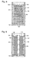
- a catalyst carrier 101 of a second embodiment is illustrated in Figure 8 .
- a bottom surface 102 closes the bottom of the container 101.
- Feet 103 extend upwardly from the bottom surface to support a monolith catalyst 104.
- An upstanding skirt 105 extends from the bottom surface 102. The skirt may be corrugated and may be flattened as in a region towards the bottom surface 102.
- a seal 106 is provided to extend from the monolith catalyst 104 and interact with the wall of the reactor tube 107.
- Baffles 108 extend upwardly for the seal. These serve to direct flow and to separate the carrier from the bottom surface of a carrier located above the carrier. The flow of gas is illustrated schematically by the arrows.
- FIG. 9 An alternative embodiment of the present invention is illustrated in Figure 9 .
- the monolith catalyst 104 has a longitudinal channel 109 therethrough.
- the feet of the first embodiment may be omitted.
- This carrier is similar in arrangement to the first embodiment.
- a top surface 110 is provided to cover the upper surface of the monolith catalyst.
- the flow of gas in the arrangement of Figure 9 is illustrated schematically by the arrows.
- the tube may be of non-circular cross-section for example, it may be a plate reactor.
- the carrier will be of the appropriate shape.
- the monolith will not be a circular ring and this term should be construed accordingly.
Landscapes
- Chemical & Material Sciences (AREA)
- Organic Chemistry (AREA)
- Chemical Kinetics & Catalysis (AREA)
- Engineering & Computer Science (AREA)
- Materials Engineering (AREA)
- Physics & Mathematics (AREA)
- Fluid Mechanics (AREA)
- Devices And Processes Conducted In The Presence Of Fluids And Solid Particles (AREA)
- Organic Low-Molecular-Weight Compounds And Preparation Thereof (AREA)
- Low-Molecular Organic Synthesis Reactions Using Catalysts (AREA)
Claims (23)
- Procédé pour la conversion de gaz de synthèse en méthanol par la mise en contact d'un courant gazeux comprenant du gaz de synthèse avec un catalyseur particulaire, ledit procédé étant effectué dans un réacteur tubulaire ayant une entrée et une sortie, ladite sortie étant située en aval de l'entrée, ledit réacteur comprenant un ou plusieurs tubes dans lesquels sont placés un ou plusieurs porteurs pour ledit catalyseur particulaire et un milieu de refroidissement en contact avec lesdits tubes ;
dans lequel ledit porteur de catalyseur comprend :un récipient annulaire destiné à contenir du catalyseur lors de l'utilisation, ledit récipient ayant une paroi interne perforée délimitant un tube, une paroi externe perforée, une surface supérieure fermant le récipient annulaire et une surface inférieure fermant le récipient annulaire ;une surface fermant le fond dudit tube formé par la paroi interne du récipient annulaire ;une jupe s'étendant vers le haut à partir de la paroi externe perforée du récipient annulaire à partir d'un endroit situé au niveau de la surface inférieure dudit récipient ou à proximité de celle-ci vers un endroit situé en dessous de l'emplacement d'un joint ; etun joint situé au niveau de la surface supérieure ou à proximité de celle-ci et s'étendant à partir du récipient sur une distance qui s'étend au-delà d'une surface externe de la jupe ; ledit procédé comprenant :(a) l'introduction des réactifs gazeux par l'entrée ;(b) le passage desdits réactifs vers le bas dans ledit ou lesdits tubes vers la surface supérieure du premier porteur de catalyseur où ils passent dans le passage délimité par la paroi perforée interne du récipient avant de passer radialement dans le lit de catalyseur vers la paroi externe perforée ;(c) le fait de laisser la réaction avoir lieu alors que le gaz de synthèse est en contact avec le catalyseur ;(d) le passage de réactif n'ayant pas réagi et de produit hors du récipient par la paroi externe perforée et ensuite vers le haut entre la surface interne de la jupe et la paroi externe du récipient annulaire jusqu'à ce qu'ils atteignent le joint où ils sont dirigés par-dessus l'extrémité de la jupe et amenés à circuler vers le bas entre la surface externe de la jupe et la surface interne du tube du réacteur où un transfert de chaleur a lieu ;(e) la répétition des étapes (b) à (d) au niveau de tout porteur de catalyseur suivant ; et(f) le soutirage du produit à partir de la sortie. - Procédé selon la revendication 1, dans lequel le catalyseur a un diamètre allant d'environ 100 µm à environ 6 mm.
- Procédé pour la conversion de gaz de synthèse en méthanol par la mise en contact d'un courant gazeux comprenant du gaz de synthèse avec un catalyseur monolithe, ledit procédé étant effectué dans un réacteur tubulaire ayant une entrée et une sortie, ladite sortie étant située en aval de l'entrée, ledit réacteur comprenant un ou plusieurs tubes dans lesquels sont placés un ou plusieurs porteurs pour ledit catalyseur monolithe et un milieu de refroidissement en contact avec lesdits tubes ;
dans lequel ledit porteur de catalyseur comprend :un récipient contenant un catalyseur monolithe, ledit récipient ayant une surface inférieure fermant le récipient et une jupe s'étendant vers le haut à partir de la surface inférieure dudit récipient vers un endroit situé en dessous de l'emplacement d'un joint et espacé de celui-ci, ladite jupe étant placée de manière à ménager un espace entre une surface externe du catalyseur monolithe et la jupe ; etun joint situé au niveau d'une surface supérieure du catalyseur monolithe ou à proximité de celle-ci et s'étendant à partir du catalyseur monolithe sur une distance qui s'étend au-delà d'une surface externe de la jupe ; ledit procédé comprenant :(a) l'introduction des réactifs gazeux par l'entrée ;(b) le passage desdits réactifs vers le bas dans ledit ou lesdits tubes vers la surface supérieure du premier catalyseur monolithe où ils passent dans le catalyseur monolithe ;(e) le fait de laisser la réaction avoir lieu alors que le gaz de synthèse est en contact avec le catalyseur ;(d) le passage de réactif n'ayant pas réagi et de produit hors du catalyseur et ensuite vers le haut entre la surface interne de la jupe et la surface externe du catalyseur monolithe jusqu'à ce qu'ils atteignent le joint où ils sont dirigés par-dessus l'extrémité de la jupe et amenés à circuler vers le bas entre la surface externe de la jupe et la surface interne du tube du réacteur où un transfert de chaleur a lieu ;(e) la répétition des étapes (b) à (d) au niveau de tout porteur de catalyseur suivant ; et(f) le soutirage du produit à partir de la sortie. - Procédé selon l'une quelconque des revendications 1 à 3, dans lequel une pluralité de porteurs de catalyseur sont empilés dans le tube du réacteur.
- Procédé selon l'une quelconque des revendications 1 à 4, dans lequel l'espace annulaire entre la surface externe du récipient de catalyseur et la surface interne de la paroi du tube est choisi pour permettre le débit de circulation de gaz nécessaire tout en maintenant un transfert de chaleur élevé et une baisse de pression faible.
- Procédé selon l'une quelconque des revendications 1 à 5, dans lequel l'espace annulaire entre la surface externe du récipient de catalyseur et la surface interne de la paroi du tube est de l'ordre d'environ 3 mm à environ 15 mm.
- Procédé selon l'une quelconque des revendications 1 à 6, dans lequel les tubes ont un diamètre dans la région d'environ 75 mm à environ 200 mm.
- Procédé selon l'une quelconque des revendications 1 à 7, dans lequel environ 200 porteurs ou plus se trouvent dans un seul tube.
- Procédé selon l'une quelconque des revendications 1 à 8, dans lequel une pluralité de réacteurs sont utilisés en parallèle.
- Procédé selon l'une quelconque des revendications 1 à 9, dans lequel le gaz n'ayant pas réagi qui sort par la sortie de chaque réacteur est traité pour éliminer la chaleur.
- Procédé selon la revendication 10, dans lequel le gaz soutiré n'ayant pas réagi est réutilisé.
- Procédé selon l'une quelconque des revendications 1 à 8, dans lequel deux réacteurs ou plus sont placés en série.
- Procédé selon la revendication 12 dans lequel les réacteurs placés en série sont en communication fluidique avec des installations situées entre chaque réacteur pour éliminer la chaleur.
- Procédé selon les revendications 12 ou 13, dans lequel le courant contenant de l'hydrogène et des oxydes de carbone en sortie du dernier étage de la série de réacteurs interconnectés est recyclé vers un quelconque point adapté dans le procédé.
- Procédé selon la revendication 14, dans lequel le courant contenant de l'hydrogène et des oxydes de carbone en sortie du dernier étage de la série de réacteurs interconnectés est recyclé vers le premier réacteur.
- Procédé selon la revendication 9, dans lequel des groupes de réacteurs parallèles communiquent en série avec des installations situées entre chaque groupe pour éliminer la chaleur.
- Procédé selon la revendication 12 ou 16 dans lequel la chaleur est réutilisée et/ou évacuée vers le refroidissement.
- Procédé selon la revendication 16, dans lequel du produit liquide est soutiré entre chaque groupe de réacteurs parallèles, le courant contenant de l'hydrogène et du monoxyde de carbone passant au groupe de réaction suivant de la série.
- Procédé selon la revendication 18, dans lequel le courant contenant de l'hydrogène et du monoxyde de carbone en sortie du dernier étage de la série de réacteurs interconnectés est recyclé vers un quelconque point adapté dans le procédé.
- Procédé selon la revendication 19, dans lequel le courant est recyclé vers l'entrée du premier réacteur.
- Procédé selon l'une quelconque des revendications 9 à 20, dans lequel un courant riche en hydrogène peut alimenter le deuxième réacteur et/ou un ou plusieurs des réacteurs suivants.
- Procédé selon l'une quelconque des revendications 1 à 21, dans lequel la température réactionnelle va d'environ 150°C à environ 330°C.
- Procédé selon l'une quelconque des revendications 1 à 22, dans lequel la pression réactionnelle va d'environ 20 bars à environ 130 bars.
Priority Applications (1)
| Application Number | Priority Date | Filing Date | Title |
|---|---|---|---|
| PL12710531T PL2531286T3 (pl) | 2011-04-27 | 2012-02-14 | Sposób syntezy metanolu |
Applications Claiming Priority (2)
| Application Number | Priority Date | Filing Date | Title |
|---|---|---|---|
| GBGB1107072.9A GB201107072D0 (en) | 2011-04-27 | 2011-04-27 | Process |
| PCT/GB2012/050330 WO2012146904A1 (fr) | 2011-04-27 | 2012-02-14 | Procédé pour la synthèse de méthanol |
Publications (2)
| Publication Number | Publication Date |
|---|---|
| EP2531286A1 EP2531286A1 (fr) | 2012-12-12 |
| EP2531286B1 true EP2531286B1 (fr) | 2014-12-03 |
Family
ID=44168641
Family Applications (1)
| Application Number | Title | Priority Date | Filing Date |
|---|---|---|---|
| EP12710531.0A Not-in-force EP2531286B1 (fr) | 2011-04-27 | 2012-02-14 | Procédé pour la synthèse de méthanol |
Country Status (17)
| Country | Link |
|---|---|
| US (1) | US8785506B2 (fr) |
| EP (1) | EP2531286B1 (fr) |
| JP (1) | JP5914638B2 (fr) |
| KR (1) | KR20140001082A (fr) |
| CN (1) | CN102858447B (fr) |
| AP (1) | AP3450A (fr) |
| AU (1) | AU2012211330B2 (fr) |
| BR (1) | BR112012019852A2 (fr) |
| CA (1) | CA2794683C (fr) |
| DK (1) | DK2531286T3 (fr) |
| EA (1) | EA201201104A1 (fr) |
| ES (1) | ES2529026T3 (fr) |
| GB (1) | GB201107072D0 (fr) |
| PL (1) | PL2531286T3 (fr) |
| TW (1) | TWI535686B (fr) |
| WO (1) | WO2012146904A1 (fr) |
| ZA (1) | ZA201205925B (fr) |
Families Citing this family (21)
| Publication number | Priority date | Publication date | Assignee | Title |
|---|---|---|---|---|
| US8951482B2 (en) * | 2010-05-20 | 2015-02-10 | Haldor Topsoe A/S | Method and apparatus for the separation of a liquid from a gas feed stream in a catalytic reactor |
| DK3099405T3 (en) * | 2014-01-29 | 2018-07-09 | Johnson Matthey Plc | Seals for use in conjunction with catalyst structures |
| GB201402782D0 (en) * | 2014-02-17 | 2014-04-02 | Johnson Matthey Davy Technologies Ltd | Process |
| GB201403787D0 (en) * | 2014-03-04 | 2014-04-16 | Johnson Matthey Plc | Steam reforming |
| GB201403788D0 (en) * | 2014-03-04 | 2014-04-16 | Johnson Matthey Plc | Catalyst arrangement |
| FR3026023B1 (fr) * | 2014-09-19 | 2016-12-23 | Commissariat Energie Atomique | Reacteur echangeur comportant des cartouches reactives amovibles au contact direct d'un circuit de fluide caloporteur |
| GB201417462D0 (en) | 2014-10-02 | 2014-11-19 | Johnson Matthey Davy Technologies Ltd | Apparatus and process |
| GB201506572D0 (en) | 2015-04-17 | 2015-06-03 | Johnson Matthey Davy Technologies Ltd | Process |
| GB201600794D0 (en) | 2016-01-15 | 2016-03-02 | Johnson Matthey Davy Technologies Ltd | Methanol process |
| GB201600793D0 (en) | 2016-01-15 | 2016-03-02 | Johnson Matthey Davy Technologies Ltd | Methanol process |
| JP6998114B2 (ja) * | 2016-12-27 | 2022-02-04 | 日亜化学工業株式会社 | 発光装置の製造方法 |
| EP3556460A1 (fr) * | 2018-04-20 | 2019-10-23 | Siemens Aktiengesellschaft | Réacteur de mise en uvre de réactions à équilibre réduit |
| JP7218155B2 (ja) * | 2018-11-07 | 2023-02-06 | 三菱重工業株式会社 | 改質装置、改質ガスの製造方法、及び改質システム |
| GB201908449D0 (en) | 2019-06-12 | 2019-07-24 | Johnson Matthey Davy Technologies Ltd | Process for synthesising methanol |
| GB201908450D0 (en) | 2019-06-12 | 2019-07-24 | Johnson Matthey Davy Technologies Ltd | Process for synthesising methanol |
| GB202015185D0 (en) | 2020-09-25 | 2020-11-11 | Johnson Matthey Davy Technologies Ltd | Improvements in or relating to catalyst carriers for tubular reactors and associated methods |
| BR112023019764A2 (pt) | 2021-05-11 | 2023-11-21 | Johnson Matthey Davy Technologies Ltd | Processo para sintetizar metanol |
| WO2022238671A1 (fr) | 2021-05-11 | 2022-11-17 | Johnson Matthey Davy Technologies Limited | Procédé de synthèse de méthanol |
| GB202109905D0 (en) | 2021-07-09 | 2021-08-25 | Johnson Matthey Plc | Process for synthesising methanol |
| GB202203700D0 (en) * | 2022-03-17 | 2022-05-04 | Johnson Matthey Davy Technologies Ltd | Improvements in or relating to catalyst carriers for tubular reactors and associated methods |
| CN114505018B (zh) * | 2022-03-30 | 2023-02-28 | 山东彩客东奥化学有限公司 | 一种BDO脱氢生产γ-丁内酯反应生产装置 |
Family Cites Families (15)
| Publication number | Priority date | Publication date | Assignee | Title |
|---|---|---|---|---|
| GB1105691A (en) | 1963-06-19 | 1968-03-13 | Iris May Cross | Improved automatically ignited oil burning heating device |
| DE2123950C3 (de) | 1971-05-14 | 1975-06-12 | Metallgesellschaft Ag, 6000 Frankfurt | Verfahren und Vorrichtung zur Herstellung von Methanol in Röhrenöfen |
| JPS5839572B2 (ja) | 1979-04-03 | 1983-08-31 | 東洋エンジニアリング株式会社 | 反応器およびその使用法 |
| DE3007202A1 (de) | 1980-02-26 | 1981-09-10 | Linde Ag, 6200 Wiesbaden | Methanol-reaktor |
| DE3266054D1 (en) | 1981-11-19 | 1985-10-10 | Ici Plc | Synthesis process and reactor |
| IN165277B (fr) | 1984-10-16 | 1989-09-09 | Kellogg M W Co | |
| US4628066A (en) | 1986-02-12 | 1986-12-09 | Air Products And Chemicals, Inc. | Process for the production of methanol |
| EP1300190A1 (fr) * | 2001-10-04 | 2003-04-09 | Methanol Casale S.A. | Reacteur pour effectuer des réactions catalytiques hétérogènes avec des éléments catalyseurs modulaires |
| MX2007001173A (es) * | 2004-01-15 | 2007-09-25 | Methanol Casale Sa | Reactor catalitico de lecho fijo. |
| EP1818094A1 (fr) * | 2006-02-13 | 2007-08-15 | Ammonia Casale S.A. | Systémes de murs pour des lits catalytiques dans des réacteurs de synthéses |
| GB0910366D0 (en) | 2009-06-17 | 2009-07-29 | Johnson Matthey Plc | Methanol synthesis process |
| GB0918246D0 (en) * | 2009-10-19 | 2009-12-02 | Davy Process Techn Ltd | Apparatus |
| GB201105691D0 (en) * | 2011-04-04 | 2011-05-18 | Davy Process Techn Ltd | Apparatus |
| GB201107070D0 (en) * | 2011-04-27 | 2011-06-08 | Davy Process Techn Ltd | FT process using can reactor |
| GB201107073D0 (en) * | 2011-04-27 | 2011-06-08 | Davy Process Techn Ltd | Process |
-
2011
- 2011-04-27 GB GBGB1107072.9A patent/GB201107072D0/en not_active Ceased
-
2012
- 2012-02-14 DK DK12710531.0T patent/DK2531286T3/en active
- 2012-02-14 US US13/581,709 patent/US8785506B2/en active Active
- 2012-02-14 EA EA201201104A patent/EA201201104A1/ru unknown
- 2012-02-14 AP AP2012006428A patent/AP3450A/xx active
- 2012-02-14 BR BR112012019852A patent/BR112012019852A2/pt not_active IP Right Cessation
- 2012-02-14 JP JP2014506927A patent/JP5914638B2/ja not_active Expired - Fee Related
- 2012-02-14 EP EP12710531.0A patent/EP2531286B1/fr not_active Not-in-force
- 2012-02-14 ES ES12710531.0T patent/ES2529026T3/es active Active
- 2012-02-14 WO PCT/GB2012/050330 patent/WO2012146904A1/fr not_active Ceased
- 2012-02-14 CA CA2794683A patent/CA2794683C/fr active Active
- 2012-02-14 PL PL12710531T patent/PL2531286T3/pl unknown
- 2012-02-14 CN CN201280001126.XA patent/CN102858447B/zh not_active Expired - Fee Related
- 2012-02-14 KR KR1020127021602A patent/KR20140001082A/ko not_active Withdrawn
- 2012-02-14 AU AU2012211330A patent/AU2012211330B2/en not_active Ceased
- 2012-03-08 TW TW101107959A patent/TWI535686B/zh not_active IP Right Cessation
- 2012-08-06 ZA ZA2012/05925A patent/ZA201205925B/en unknown
Also Published As
| Publication number | Publication date |
|---|---|
| AP2012006428A0 (en) | 2012-08-31 |
| CN102858447B (zh) | 2015-05-20 |
| CA2794683C (fr) | 2019-04-02 |
| GB201107072D0 (en) | 2011-06-08 |
| ZA201205925B (en) | 2014-01-24 |
| AU2012211330B2 (en) | 2014-09-04 |
| US8785506B2 (en) | 2014-07-22 |
| US20140107235A1 (en) | 2014-04-17 |
| CA2794683A1 (fr) | 2012-11-01 |
| KR20140001082A (ko) | 2014-01-06 |
| EP2531286A1 (fr) | 2012-12-12 |
| WO2012146904A1 (fr) | 2012-11-01 |
| PL2531286T3 (pl) | 2015-04-30 |
| TW201242937A (en) | 2012-11-01 |
| ES2529026T3 (es) | 2015-02-16 |
| BR112012019852A2 (pt) | 2016-04-19 |
| CN102858447A (zh) | 2013-01-02 |
| DK2531286T3 (en) | 2014-12-15 |
| AP3450A (en) | 2015-10-31 |
| JP2014516938A (ja) | 2014-07-17 |
| AU2012211330A1 (en) | 2012-11-15 |
| JP5914638B2 (ja) | 2016-05-11 |
| TWI535686B (zh) | 2016-06-01 |
| EA201201104A1 (ru) | 2013-01-30 |
Similar Documents
| Publication | Publication Date | Title |
|---|---|---|
| EP2531286B1 (fr) | Procédé pour la synthèse de méthanol | |
| CA2789370C (fr) | Procede fischer-tropsch dans un reacteur radial | |
| US12226764B2 (en) | Annular catalyst carrier container for use in a tubular reactor | |
| CA2794681A1 (fr) | Procede de production d'anhydrides | |
| OA17844A (en) | Process for the synthesis of methanol. |
Legal Events
| Date | Code | Title | Description |
|---|---|---|---|
| PUAI | Public reference made under article 153(3) epc to a published international application that has entered the european phase |
Free format text: ORIGINAL CODE: 0009012 |
|
| 17P | Request for examination filed |
Effective date: 20120727 |
|
| AK | Designated contracting states |
Kind code of ref document: A1 Designated state(s): AL AT BE BG CH CY CZ DE DK EE ES FI FR GB GR HR HU IE IS IT LI LT LU LV MC MK MT NL NO PL PT RO RS SE SI SK SM TR |
|
| RIN1 | Information on inventor provided before grant (corrected) |
Inventor name: GAMLIN, TIMOTHY DOUGLAS |
|
| RAP1 | Party data changed (applicant data changed or rights of an application transferred) |
Owner name: JOHNSON MATTHEY DAVY TECHNOLOGIES LIMITED |
|
| DAX | Request for extension of the european patent (deleted) | ||
| GRAP | Despatch of communication of intention to grant a patent |
Free format text: ORIGINAL CODE: EPIDOSNIGR1 |
|
| INTG | Intention to grant announced |
Effective date: 20140822 |
|
| GRAS | Grant fee paid |
Free format text: ORIGINAL CODE: EPIDOSNIGR3 |
|
| GRAA | (expected) grant |
Free format text: ORIGINAL CODE: 0009210 |
|
| AK | Designated contracting states |
Kind code of ref document: B1 Designated state(s): AL AT BE BG CH CY CZ DE DK EE ES FI FR GB GR HR HU IE IS IT LI LT LU LV MC MK MT NL NO PL PT RO RS SE SI SK SM TR |
|
| REG | Reference to a national code |
Ref country code: GB Ref legal event code: FG4D |
|
| REG | Reference to a national code |
Ref country code: DK Ref legal event code: T3 Effective date: 20141211 Ref country code: CH Ref legal event code: EP Ref country code: AT Ref legal event code: REF Ref document number: 699035 Country of ref document: AT Kind code of ref document: T Effective date: 20141215 |
|
| REG | Reference to a national code |
Ref country code: SE Ref legal event code: TRGR |
|
| REG | Reference to a national code |
Ref country code: IE Ref legal event code: FG4D |
|
| REG | Reference to a national code |
Ref country code: DE Ref legal event code: R096 Ref document number: 602012004133 Country of ref document: DE Effective date: 20150115 |
|
| REG | Reference to a national code |
Ref country code: NL Ref legal event code: T3 |
|
| REG | Reference to a national code |
Ref country code: NO Ref legal event code: T2 Effective date: 20141203 |
|
| REG | Reference to a national code |
Ref country code: FR Ref legal event code: PLFP Year of fee payment: 4 |
|
| REG | Reference to a national code |
Ref country code: ES Ref legal event code: FG2A Ref document number: 2529026 Country of ref document: ES Kind code of ref document: T3 Effective date: 20150216 |
|
| REG | Reference to a national code |
Ref country code: AT Ref legal event code: MK05 Ref document number: 699035 Country of ref document: AT Kind code of ref document: T Effective date: 20141203 |
|
| PG25 | Lapsed in a contracting state [announced via postgrant information from national office to epo] |
Ref country code: LT Free format text: LAPSE BECAUSE OF FAILURE TO SUBMIT A TRANSLATION OF THE DESCRIPTION OR TO PAY THE FEE WITHIN THE PRESCRIBED TIME-LIMIT Effective date: 20141203 |
|
| REG | Reference to a national code |
Ref country code: PL Ref legal event code: T3 |
|
| REG | Reference to a national code |
Ref country code: LT Ref legal event code: MG4D |
|
| PG25 | Lapsed in a contracting state [announced via postgrant information from national office to epo] |
Ref country code: LV Free format text: LAPSE BECAUSE OF FAILURE TO SUBMIT A TRANSLATION OF THE DESCRIPTION OR TO PAY THE FEE WITHIN THE PRESCRIBED TIME-LIMIT Effective date: 20141203 Ref country code: GR Free format text: LAPSE BECAUSE OF FAILURE TO SUBMIT A TRANSLATION OF THE DESCRIPTION OR TO PAY THE FEE WITHIN THE PRESCRIBED TIME-LIMIT Effective date: 20150304 Ref country code: RS Free format text: LAPSE BECAUSE OF FAILURE TO SUBMIT A TRANSLATION OF THE DESCRIPTION OR TO PAY THE FEE WITHIN THE PRESCRIBED TIME-LIMIT Effective date: 20141203 Ref country code: HR Free format text: LAPSE BECAUSE OF FAILURE TO SUBMIT A TRANSLATION OF THE DESCRIPTION OR TO PAY THE FEE WITHIN THE PRESCRIBED TIME-LIMIT Effective date: 20141203 Ref country code: AT Free format text: LAPSE BECAUSE OF FAILURE TO SUBMIT A TRANSLATION OF THE DESCRIPTION OR TO PAY THE FEE WITHIN THE PRESCRIBED TIME-LIMIT Effective date: 20141203 Ref country code: CY Free format text: LAPSE BECAUSE OF FAILURE TO SUBMIT A TRANSLATION OF THE DESCRIPTION OR TO PAY THE FEE WITHIN THE PRESCRIBED TIME-LIMIT Effective date: 20141203 |
|
| PG25 | Lapsed in a contracting state [announced via postgrant information from national office to epo] |
Ref country code: CZ Free format text: LAPSE BECAUSE OF FAILURE TO SUBMIT A TRANSLATION OF THE DESCRIPTION OR TO PAY THE FEE WITHIN THE PRESCRIBED TIME-LIMIT Effective date: 20141203 Ref country code: SK Free format text: LAPSE BECAUSE OF FAILURE TO SUBMIT A TRANSLATION OF THE DESCRIPTION OR TO PAY THE FEE WITHIN THE PRESCRIBED TIME-LIMIT Effective date: 20141203 Ref country code: PT Free format text: LAPSE BECAUSE OF FAILURE TO SUBMIT A TRANSLATION OF THE DESCRIPTION OR TO PAY THE FEE WITHIN THE PRESCRIBED TIME-LIMIT Effective date: 20150403 Ref country code: RO Free format text: LAPSE BECAUSE OF FAILURE TO SUBMIT A TRANSLATION OF THE DESCRIPTION OR TO PAY THE FEE WITHIN THE PRESCRIBED TIME-LIMIT Effective date: 20141203 Ref country code: EE Free format text: LAPSE BECAUSE OF FAILURE TO SUBMIT A TRANSLATION OF THE DESCRIPTION OR TO PAY THE FEE WITHIN THE PRESCRIBED TIME-LIMIT Effective date: 20141203 |
|
| PG25 | Lapsed in a contracting state [announced via postgrant information from national office to epo] |
Ref country code: IS Free format text: LAPSE BECAUSE OF FAILURE TO SUBMIT A TRANSLATION OF THE DESCRIPTION OR TO PAY THE FEE WITHIN THE PRESCRIBED TIME-LIMIT Effective date: 20150403 |
|
| REG | Reference to a national code |
Ref country code: DE Ref legal event code: R097 Ref document number: 602012004133 Country of ref document: DE |
|
| PG25 | Lapsed in a contracting state [announced via postgrant information from national office to epo] |
Ref country code: LU Free format text: LAPSE BECAUSE OF FAILURE TO SUBMIT A TRANSLATION OF THE DESCRIPTION OR TO PAY THE FEE WITHIN THE PRESCRIBED TIME-LIMIT Effective date: 20150214 |
|
| REG | Reference to a national code |
Ref country code: CH Ref legal event code: PL |
|
| PLBE | No opposition filed within time limit |
Free format text: ORIGINAL CODE: 0009261 |
|
| STAA | Information on the status of an ep patent application or granted ep patent |
Free format text: STATUS: NO OPPOSITION FILED WITHIN TIME LIMIT |
|
| PG25 | Lapsed in a contracting state [announced via postgrant information from national office to epo] |
Ref country code: MC Free format text: LAPSE BECAUSE OF FAILURE TO SUBMIT A TRANSLATION OF THE DESCRIPTION OR TO PAY THE FEE WITHIN THE PRESCRIBED TIME-LIMIT Effective date: 20141203 Ref country code: LI Free format text: LAPSE BECAUSE OF NON-PAYMENT OF DUE FEES Effective date: 20150228 Ref country code: CH Free format text: LAPSE BECAUSE OF NON-PAYMENT OF DUE FEES Effective date: 20150228 |
|
| 26N | No opposition filed |
Effective date: 20150904 |
|
| REG | Reference to a national code |
Ref country code: IE Ref legal event code: MM4A |
|
| REG | Reference to a national code |
Ref country code: FR Ref legal event code: PLFP Year of fee payment: 5 |
|
| PG25 | Lapsed in a contracting state [announced via postgrant information from national office to epo] |
Ref country code: IE Free format text: LAPSE BECAUSE OF NON-PAYMENT OF DUE FEES Effective date: 20150214 |
|
| PG25 | Lapsed in a contracting state [announced via postgrant information from national office to epo] |
Ref country code: SI Free format text: LAPSE BECAUSE OF FAILURE TO SUBMIT A TRANSLATION OF THE DESCRIPTION OR TO PAY THE FEE WITHIN THE PRESCRIBED TIME-LIMIT Effective date: 20141203 |
|
| PGFP | Annual fee paid to national office [announced via postgrant information from national office to epo] |
Ref country code: TR Payment date: 20160126 Year of fee payment: 5 Ref country code: IT Payment date: 20160222 Year of fee payment: 5 Ref country code: DE Payment date: 20160209 Year of fee payment: 5 Ref country code: ES Payment date: 20160127 Year of fee payment: 5 Ref country code: NO Payment date: 20160209 Year of fee payment: 5 Ref country code: DK Payment date: 20160210 Year of fee payment: 5 |
|
| PG25 | Lapsed in a contracting state [announced via postgrant information from national office to epo] |
Ref country code: BE Free format text: LAPSE BECAUSE OF FAILURE TO SUBMIT A TRANSLATION OF THE DESCRIPTION OR TO PAY THE FEE WITHIN THE PRESCRIBED TIME-LIMIT Effective date: 20141203 |
|
| PGFP | Annual fee paid to national office [announced via postgrant information from national office to epo] |
Ref country code: SE Payment date: 20160211 Year of fee payment: 5 Ref country code: FR Payment date: 20160125 Year of fee payment: 5 Ref country code: FI Payment date: 20160209 Year of fee payment: 5 Ref country code: PL Payment date: 20160128 Year of fee payment: 5 Ref country code: NL Payment date: 20160210 Year of fee payment: 5 |
|
| PG25 | Lapsed in a contracting state [announced via postgrant information from national office to epo] |
Ref country code: MT Free format text: LAPSE BECAUSE OF FAILURE TO SUBMIT A TRANSLATION OF THE DESCRIPTION OR TO PAY THE FEE WITHIN THE PRESCRIBED TIME-LIMIT Effective date: 20141203 |
|
| PG25 | Lapsed in a contracting state [announced via postgrant information from national office to epo] |
Ref country code: BG Free format text: LAPSE BECAUSE OF FAILURE TO SUBMIT A TRANSLATION OF THE DESCRIPTION OR TO PAY THE FEE WITHIN THE PRESCRIBED TIME-LIMIT Effective date: 20141203 Ref country code: HU Free format text: LAPSE BECAUSE OF FAILURE TO SUBMIT A TRANSLATION OF THE DESCRIPTION OR TO PAY THE FEE WITHIN THE PRESCRIBED TIME-LIMIT; INVALID AB INITIO Effective date: 20120214 Ref country code: SM Free format text: LAPSE BECAUSE OF FAILURE TO SUBMIT A TRANSLATION OF THE DESCRIPTION OR TO PAY THE FEE WITHIN THE PRESCRIBED TIME-LIMIT Effective date: 20141203 |
|
| REG | Reference to a national code |
Ref country code: DE Ref legal event code: R119 Ref document number: 602012004133 Country of ref document: DE |
|
| REG | Reference to a national code |
Ref country code: DK Ref legal event code: EBP Effective date: 20170228 |
|
| REG | Reference to a national code |
Ref country code: NO Ref legal event code: MMEP |
|
| REG | Reference to a national code |
Ref country code: SE Ref legal event code: EUG |
|
| REG | Reference to a national code |
Ref country code: NL Ref legal event code: MM Effective date: 20170301 |
|
| PG25 | Lapsed in a contracting state [announced via postgrant information from national office to epo] |
Ref country code: NO Free format text: LAPSE BECAUSE OF NON-PAYMENT OF DUE FEES Effective date: 20170228 Ref country code: FI Free format text: LAPSE BECAUSE OF NON-PAYMENT OF DUE FEES Effective date: 20170214 |
|
| PG25 | Lapsed in a contracting state [announced via postgrant information from national office to epo] |
Ref country code: SE Free format text: LAPSE BECAUSE OF NON-PAYMENT OF DUE FEES Effective date: 20170215 Ref country code: NL Free format text: LAPSE BECAUSE OF NON-PAYMENT OF DUE FEES Effective date: 20170301 |
|
| REG | Reference to a national code |
Ref country code: FR Ref legal event code: ST Effective date: 20171031 |
|
| PG25 | Lapsed in a contracting state [announced via postgrant information from national office to epo] |
Ref country code: DK Free format text: LAPSE BECAUSE OF NON-PAYMENT OF DUE FEES Effective date: 20170228 Ref country code: FR Free format text: LAPSE BECAUSE OF NON-PAYMENT OF DUE FEES Effective date: 20170228 Ref country code: DE Free format text: LAPSE BECAUSE OF NON-PAYMENT OF DUE FEES Effective date: 20170901 |
|
| PG25 | Lapsed in a contracting state [announced via postgrant information from national office to epo] |
Ref country code: IT Free format text: LAPSE BECAUSE OF NON-PAYMENT OF DUE FEES Effective date: 20170214 |
|
| REG | Reference to a national code |
Ref country code: ES Ref legal event code: FD2A Effective date: 20180628 |
|
| PG25 | Lapsed in a contracting state [announced via postgrant information from national office to epo] |
Ref country code: MK Free format text: LAPSE BECAUSE OF FAILURE TO SUBMIT A TRANSLATION OF THE DESCRIPTION OR TO PAY THE FEE WITHIN THE PRESCRIBED TIME-LIMIT Effective date: 20141203 |
|
| PG25 | Lapsed in a contracting state [announced via postgrant information from national office to epo] |
Ref country code: ES Free format text: LAPSE BECAUSE OF NON-PAYMENT OF DUE FEES Effective date: 20170215 |
|
| PG25 | Lapsed in a contracting state [announced via postgrant information from national office to epo] |
Ref country code: PL Free format text: LAPSE BECAUSE OF NON-PAYMENT OF DUE FEES Effective date: 20170214 |
|
| PG25 | Lapsed in a contracting state [announced via postgrant information from national office to epo] |
Ref country code: AL Free format text: LAPSE BECAUSE OF FAILURE TO SUBMIT A TRANSLATION OF THE DESCRIPTION OR TO PAY THE FEE WITHIN THE PRESCRIBED TIME-LIMIT Effective date: 20141203 |
|
| PG25 | Lapsed in a contracting state [announced via postgrant information from national office to epo] |
Ref country code: TR Free format text: LAPSE BECAUSE OF NON-PAYMENT OF DUE FEES Effective date: 20170214 |
|
| P01 | Opt-out of the competence of the unified patent court (upc) registered |
Effective date: 20230526 |
|
| PGFP | Annual fee paid to national office [announced via postgrant information from national office to epo] |
Ref country code: GB Payment date: 20240123 Year of fee payment: 13 |
|
| GBPC | Gb: european patent ceased through non-payment of renewal fee |
Effective date: 20250214 |
|
| PG25 | Lapsed in a contracting state [announced via postgrant information from national office to epo] |
Ref country code: GB Free format text: LAPSE BECAUSE OF NON-PAYMENT OF DUE FEES Effective date: 20250214 |