EP2532815B1 - Diebstahlsicherung - Google Patents
Diebstahlsicherung Download PDFInfo
- Publication number
- EP2532815B1 EP2532815B1 EP11174164.1A EP11174164A EP2532815B1 EP 2532815 B1 EP2532815 B1 EP 2532815B1 EP 11174164 A EP11174164 A EP 11174164A EP 2532815 B1 EP2532815 B1 EP 2532815B1
- Authority
- EP
- European Patent Office
- Prior art keywords
- theft device
- cavity
- shaped body
- shell
- mounting surface
- Prior art date
- Legal status (The legal status is an assumption and is not a legal conclusion. Google has not performed a legal analysis and makes no representation as to the accuracy of the status listed.)
- Active
Links
Images


Classifications
-
- E—FIXED CONSTRUCTIONS
- E05—LOCKS; KEYS; WINDOW OR DOOR FITTINGS; SAFES
- E05B—LOCKS; ACCESSORIES THEREFOR; HANDCUFFS
- E05B73/00—Devices for locking portable objects against unauthorised removal; Miscellaneous locking devices
- E05B73/0017—Anti-theft devices, e.g. tags or monitors, fixed to articles, e.g. clothes, and to be removed at the check-out of shops
- E05B73/0035—Anti-theft devices, e.g. tags or monitors, fixed to articles, e.g. clothes, and to be removed at the check-out of shops for eyeglasses or spectacles
-
- E—FIXED CONSTRUCTIONS
- E05—LOCKS; KEYS; WINDOW OR DOOR FITTINGS; SAFES
- E05B—LOCKS; ACCESSORIES THEREFOR; HANDCUFFS
- E05B73/00—Devices for locking portable objects against unauthorised removal; Miscellaneous locking devices
- E05B73/0017—Anti-theft devices, e.g. tags or monitors, fixed to articles, e.g. clothes, and to be removed at the check-out of shops
-
- Y—GENERAL TAGGING OF NEW TECHNOLOGICAL DEVELOPMENTS; GENERAL TAGGING OF CROSS-SECTIONAL TECHNOLOGIES SPANNING OVER SEVERAL SECTIONS OF THE IPC; TECHNICAL SUBJECTS COVERED BY FORMER USPC CROSS-REFERENCE ART COLLECTIONS [XRACs] AND DIGESTS
- Y10—TECHNICAL SUBJECTS COVERED BY FORMER USPC
- Y10T—TECHNICAL SUBJECTS COVERED BY FORMER US CLASSIFICATION
- Y10T24/00—Buckles, buttons, clasps, etc.
- Y10T24/50—Readily interlocking, two-part fastener requiring either destructive or tool disengagement
-
- Y—GENERAL TAGGING OF NEW TECHNOLOGICAL DEVELOPMENTS; GENERAL TAGGING OF CROSS-SECTIONAL TECHNOLOGIES SPANNING OVER SEVERAL SECTIONS OF THE IPC; TECHNICAL SUBJECTS COVERED BY FORMER USPC CROSS-REFERENCE ART COLLECTIONS [XRACs] AND DIGESTS
- Y10—TECHNICAL SUBJECTS COVERED BY FORMER USPC
- Y10T—TECHNICAL SUBJECTS COVERED BY FORMER US CLASSIFICATION
- Y10T70/00—Locks
- Y10T70/40—Portable
- Y10T70/411—Clamps
-
- Y—GENERAL TAGGING OF NEW TECHNOLOGICAL DEVELOPMENTS; GENERAL TAGGING OF CROSS-SECTIONAL TECHNOLOGIES SPANNING OVER SEVERAL SECTIONS OF THE IPC; TECHNICAL SUBJECTS COVERED BY FORMER USPC CROSS-REFERENCE ART COLLECTIONS [XRACs] AND DIGESTS
- Y10—TECHNICAL SUBJECTS COVERED BY FORMER USPC
- Y10T—TECHNICAL SUBJECTS COVERED BY FORMER US CLASSIFICATION
- Y10T70/00—Locks
- Y10T70/50—Special application
- Y10T70/5004—For antitheft signaling device on protected article
-
- Y—GENERAL TAGGING OF NEW TECHNOLOGICAL DEVELOPMENTS; GENERAL TAGGING OF CROSS-SECTIONAL TECHNOLOGIES SPANNING OVER SEVERAL SECTIONS OF THE IPC; TECHNICAL SUBJECTS COVERED BY FORMER USPC CROSS-REFERENCE ART COLLECTIONS [XRACs] AND DIGESTS
- Y10—TECHNICAL SUBJECTS COVERED BY FORMER USPC
- Y10T—TECHNICAL SUBJECTS COVERED BY FORMER US CLASSIFICATION
- Y10T70/00—Locks
- Y10T70/50—Special application
- Y10T70/5009—For portable articles
Definitions
- the present invention relates to an anti-theft device, also known as anti-shoplifting device, used to protect objects, in e.g. shops, supermarkets, warehouses and similar, and to avoid/discourage the actions of thieves.
- the anti-theft device of the present invention is particularly useful and suitable to protect glasses, but it can be used for basically all objects, such as, e.g., shoes or clothes.
- Anti-theft devices are well known in the art and they usually consist of a body which is somehow fixed on the object to be protected and include a detection/signaling system capable of generating alarms when passed through check-points.
- An anti-theft device according to the preamble of claim 1 is for example known from document WO 99/36653 A1 .
- the basic requirements for an effective anti-theft device include the possibility of being easily applied and rapidly removed by authorized personnel, maintaining at the same time the practical impossibility of being removed by un-authorized personnel.
- the mechanism for fixing them onto the object to be protected includes special designed actuating part that can be operated by corresponding special designed tools, e.g. special designed screwheads actuated by special designed screwdrivers.
- the mechanism for fixing an anti-theft device onto the object to be protected can include magnetically actuated locking mechanism in which the fixing mechanism of the device is unlocked by a magnet used by, e.g., a shop assistant when the object is sold.
- a magnet used by, e.g., a shop assistant when the object is sold.
- a further problem is due to the relatively bulky structure of the anti-theft devices, particularly when they house magnetic or electronic signaling/detection cards or circuits and when they are used to protect relatively small object, e.g. glasses or sunglasses, in which the aesthetic appearance is extremely important to determine the consumer choices.
- the anti-theft devices applied on glasses are relatively bulky and they laterally project from the glasses, so as to change the visual impact of the glasses and make it difficult to appreciate their aesthetic appearance.
- it is difficult to appreciate the design of the glasses since a relevant part thereof is substantially hidden by the anti-theft device applied thereto.
- an object of the present invention to provide an anti-theft device, particularly for glasses, having a reduced visual impact with respect to the conventional anti-theft devices.
- the present invention is aimed at providing an anti-theft device, particularly for glasses, which can be easily applied and rapidly removed by authorized personnel only.
- a further object of the present invention is to provide an anti-theft device, particularly for glasses, in which the lateral projection from the arm of the glasses is reduced.
- Another object of the present invention is to provide an anti-theft device, particularly for glasses, which does not hide relevant parts of the object to be protected.
- Another object of the present invention is to provide an anti-theft device, particularly for glasses, having a reduced number of mechanical parts.
- Another object of the present invention is to provide an anti-theft device, particularly for glasses, having improved functionality.
- Still another object of the present invention is to provide an anti-theft device, particularly for glasses, with reduced manufacturing costs.
- the present invention relates to an anti-theft device comprising a first shaped body having a first mounting portion for mounting said device on an object to be protected and a second detection portion for supporting/housing means of signalling/detection, said first mounting portion including a first mounting surface and a first cavity housing first locking means, said anti-theft device further comprising a second shaped body comprising a first locking portion positioned internally to said first cavity and a second mounting portion comprising a second mounting surface, said first locking portion comprising second locking means coupled to said first locking means, the actioning of said first locking means determining the sliding of said second shaped body within said first cavity and the movement of said second mounting surface toward said first mounting surface, characterized in that said second shaped body has a substantially parallelepipedic shape, with a first, second, third and fourth side that define an internal open space.
- the presence of the second shaped body partially sliding inside the first cavity when the anti-theft device is fixed onto the object to be protected allows to greatly reduce the visual impact of the anti-theft device when it is mounted onto, e.g. an arm of glasses.
- the second mounting surface is drawn towards the first mounting surface thereby reducing the lateral projection of the anti-theft device when mounted onto the arm of glasses or onto other objects to be protected.
- the second detection portion which supports/houses the means of signalling/detection can be very slim thereby further reducing the visual impact of the anti-theft device once mounted on the arm of glasses.
- the mounting/removal of the anti-theft device onto the object to be protected can be carried out in very simple manner by the authorized personnel by acting on the first locking means, e.g. screw means, that are conveniently shaped so as to be actuated only by specially designed tools, e.g. a screwdriver with a special head.
- first locking means e.g. screw means
- specially designed tools e.g. a screwdriver with a special head.
- the anti-theft device of the invention can be realized with a reduced number of pieces and with reduced mechanical complexity, thereby reducing the manufacturing costs.
- the locking means comprises screw means positioned in a substantially fixed position in said first cavity and rotationally movable with respect to their longitudinal axis.
- the screw means draw the second shaped body, and consequently the second mounting surface, toward the first shaped body and the first mounting surface, thereby reducing the overall dimensions of the devices and its visual impact.
- the second locking means comprises a threaded hole positioned on a first side of said second shaped body, said screw means being engaged in said threaded hole.
- the first cavity has a base that defines said first mounting surface.
- said screw means preferably rest on said base, and, for instance, they can be rotationally mounted on a pin on said base.
- the second mounting surface can be positioned on said third side of said second shaped body facing on said internal open space.
- the first shaped body comprises a first and a second half-shell coupled together, with said first and second half-shells preferably defining a second cavity for housing said means of signalling/detection.
- the first half-shell can be substantially planar and can have raised edges mating corresponding edges on said a second half-shell, said first half-shell further having coupling means for coupling with said second half-shell.
- the second half shell can have a first raised portion defining said first cavity and a second raised portion defining said second cavity.
- the first and second mounting surface are preferably covered with a soft protection material, e.g. silicon rubber or any soft material capable of avoiding damages due to the locking action of the device onto the obj ect.
- a soft protection material e.g. silicon rubber or any soft material capable of avoiding damages due to the locking action of the device onto the obj ect.
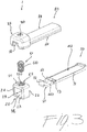
- an anti-theft device designed with the reference number 1, comprises, in its more general definition, a first shaped body 10 which has a first mounting portion 11 for mounting said device on an object to be protected, e.g. an arm of glasses.
- the first shaped body 10 further comprises a second detection portion 12 for supporting/housing means of signalling/detection, which can be, for example, a bar code or a magnetic card applied onto the surface or housed into a cavity of the second portion 12 of the devices, so as to be readable by the alarm devices usually present in checkpoints of a shop.
- the means of signalling/detection can be of any type and are well know in the art; they will not be described in further details in the present document.
- the said first mounting portion 11 includes a first mounting surface 31 and a first cavity 41 housing first locking means 51, whose functionality will be better described hereinafter.
- the anti-theft 1 device further comprises a second shaped body 20 which in turn comprises a first locking portion 25 which is positioned internally to said first cavity 41 and a second mounting portion 26 which comprises a second mounting surface 32.
- first locking portion 25 of the second shaped body 20 comprises second locking means 52 which are coupled to said first locking means 51, so that by acting on said first locking means 51, the second shaped body 20 slides within said first cavity 41; at the same time the second mounting surface 32 moves toward the first mounting surface 31.
- one of the mounting surfaces is drawn toward the other and toward the interior of the device, thereby reducing the overall volume and encumbrance of the device once mounted onto the object.
- the first locking means 51 preferably comprise, for example, screw means 510 which are positioned in a substantially fixed position in said first cavity 41 and rotationally movable with respect to their longitudinal axis.
- the screw means 510 are positioned in the first cavity 41 so as not to shift with respect to it, but being free to rotate with respect to their longitudinal axis.
- the screw means 510 are coupled to the second shaped body 20 through the second locking means 52, by rotating the screw means 510 they draw the second shaped body 20 inside the first cavity 41 and, consequently, the second mounting surface 32 toward the first mounting surface 31 until the first is in close contact with the latter.
- the anti-theft device becomes fixed on said object in a way that cannot be removed.
- the second shaped body 20 has a substantially parallelepipedic shape, with a first 21, second 22, third 23 and fourth 24 side that define an internal open space 29.
- the second locking means 52 preferably comprise a threaded hole 520 which positioned on said first side 21 of the second shaped body 20, said screw means 510 being engaged in said threaded hole 520.
- threaded hole 520 is positioned in the first locking portion 25 which in turn is positioned internally to said first cavity 41.
- the first cavity 41 has a base 410 that defines said first mounting surface 31.
- the screw means 510 advantageously rest on said base 410 and can be, for instance, rotationally mounted on a pin 61 on said base 410.
- the second mounting surface 32 can be conveniently positioned on the third side 23 of said second shaped body 20 facing on said internal open space 29.
- the said first shaped body 10 comprises a first 70 and a second 80 half-shell which are coupled together.
- first 70 and second 80 half-shells In this way it can be possible, by appropriately shaping the first 70 and second 80 half-shells, to define, in addition to the first cavity 41, also a second cavity 42 for housing said means of signalling/detection.
- first half-shell 70 can be conveniently planar and can have raised edges 71 mating corresponding edges 81 on said second half-shell 80. Furthermore, the first half-shell 70 can have coupling means for coupling with said second half-shell 80.
- the second half shell 80 preferably has a first raised portion 88 which defines the first cavity 41 and a second raised portion 89 which defines the second cavity 42. Moreover, a hole 90 is defined in said first raised portion 88 for accessing said first locking means 51, e.g. the head of the screw means 510.
- an anti-theft device can be realized with only four pieces, namely: the first half-shell 70, the second half-shell 80, the second shaped body 20, and the screw means 510.
- the first half-shell 70 has a portion that define the lower part of the second cavity 42 and a portion that defines the base 410 of the first cavity 41; on said base 410, a pin 61 for engaging the screw means 510 is conveniently positioned.
- the first mounting surface 31 is defined on said portion that defines the base 410, on the opposite side with respect to said base 410.
- the second shaped body 20 has a substantially parallelepipedic shape, with a first 21, a second 22, a third 23 and a fourth 24 side that define an internal open space 29.
- the surface of the third side 23 facing into the internal open space 29 constitutes the second mounting surface 32.
- the second half shell 80 has a first raised portion 88 which defines the first cavity 41 and is positioned above the base 410 defined on the first half shell 70. Moreover the second half shell 80 has a second raised portion 89 which, together with the corresponding portion of the first half shell 70, defines the second cavity 42. A hole 90 is defined in the first raised portion 88 for accessing the head of the screw means 510.
- the assembly of the anti-theft device 1 is very simple.
- the first half shell 70 is inserted into the internal open space 29 of the second shaped body 20, so that the first mounting surface 31 is faced to the second mounting surface 32 (see fig. 4 ).
- the screw means 510 are screwed into the threaded hole 520 until they are engaged into the pin 61.
- the second half shell 80 is positioned on the first half shell 70 and fixed to it, so as to realize the final structure shown in figure 2 , in which the first locking portion 25 of the second shaped body 20 is inglobated inside the first cavity 41.
- the second shaped body By acting on the head of the screw means 510 and rotating them, the second shaped body is moved with respect to the assembly consisting of the first 70 and second 80 half shells, thereby moving the second mounting surface 32 away from / close to the first mounting surface 31.
- the anti-theft device By inserting a piece of an object, e.g. an arm of glasses in the space between said first and second mounting surfaces 31, 32, the anti-theft device can be fixed/removed form said obj ect.
- the removal of the anti-theft device can be carried out only by authorized personnel, with a corresponding special designed tool, e.g. special designed screwdriver.
- the first half shell 70 has a first tooth 72 mating a cut-out section 82 in the peripheral walls of said first raised portion 88, and first interlocking means 73 snap-fitting with second interlocking means 83 of said second half shell 80.
- first interlocking means 73 snap-fitting with second interlocking means 83 of said second half shell 80.
- said first 31 and second 32 mounting surfaces are covered with a soft protection material, e.g. silicon or similar rubbers.
- the anti-theft device of the invention allows to achieve all the intended objects, overcoming the problems of the prior art devices.
- the encumbrance of the device is limited, thereby limiting its visual impact.
- the lateral projection from the arm is very limited, due to the fact that the second shaped body is drawn inside the first cavity, with the second mounting surface being drawn toward the first mounting surface.
- the anti-theft device can be kept very slim, thereby further limiting its visual impact.
- the anti-theft device can be realized in a relatively simple manner, with reduced mechanical complexity and with a reduced number of pieces, in particular with only four pieces.
- suitable shaped locking means e.g. suitable shaped heads of screw means, that cannot be operated with conventional tools.
- the anti-theft device thus conceived may undergo numerous modifications and come in several variants, all coming within the scope of the invention, as defined by the claims.
- the component materials and dimensions of the device may be of any nature, according to need and the state of the art.
Landscapes
- Burglar Alarm Systems (AREA)
Claims (13)
- Antidiebstahlvorrichtung (1), aufweisend einen ersten geformten Körper (10) mit einem ersten Befestigungsabschnitt (11) zum Befestigen der Vorrichtung an einem zu schützenden Objekt und einem zweiten Erfassungsabschnitt (12) zum Tragen/Aufnehmen von Signal-/Erfassungseinrichtungen, wobei der Befestigungsabschnitt (11) eine erste Befestigungsoberfläche (31) und eine erste Vertiefung (41) beinhaltet, die eine erste Sperreinrichtung (51) beherbergt, wobei die Antidiebstahlvorrichtung (1) ferner einen zweiten geformten Körper (20) aufweist, der einen ersten Sperrabschnitt (25), der innerhalb der ersten Vertiefung (41) positioniert ist, und einen zweiten Befestigungsabschnitt (26), der eine zweite Befestigungsoberfläche (32) aufweist, aufweist, wobei der erste Sperrabschnitt (25) eine zweite Sperreinrichtung (52) aufweist, die mit der ersten Sperreinrichtung (51) gekoppelt ist,
wobei die Betätigung der ersten Sperreinrichtung (51) das Gleiten des zweiten geformten Körpers (20) innerhalb der ersten Vertiefung (41) und die Bewegung der zweiten Befestigungsoberfläche (32) in Richtung der ersten Befestigungsoberfläche (31) bestimmt,
dadurch gekennzeichnet, dass der zweite geformte Körper (20) eine im Wesentlichen parallelepipedische Form aufweist, mit einer ersten (21), zweiten (22), dritten (23) und vierten (24) Seite, die einen inneren offenen Raum (29) begrenzen. - Antidiebstahlvorrichtung (1) nach Anspruch 1, dadurch gekennzeichnet, dass die erste Sperreinrichtung (51) eine Schraubeinrichtung (510) aufweist, die in einer im Wesentlichen festen Position in der ersten Vertiefung (41) positioniert ist und im Hinblick auf ihre Längsachse drehend beweglich ist.
- Antidiebstahlvorrichtung (1) nach Anspruch 2, dadurch gekennzeichnet, dass die zweite Sperreinrichtung (52) eine Gewindebohrung (520) aufweist, die an der ersten Seite (21) des zweiten geformten Körpers (20) positioniert ist, wobei sich die Schraubeinrichtung (510) mit der Gewindebohrung (520) in Eingriff befindet.
- Antidiebstahlvorrichtung (1) nach einem oder mehreren der vorgenannten Ansprüche, dadurch gekennzeichnet, dass die erste Vertiefung (41) ein Unterteil (410) aufweist, das die erste Befestigungsoberfläche (31) definiert.
- Antidiebstahlvorrichtung (1) nach Anspruch 4, dadurch gekennzeichnet, dass die Schraubeinrichtung auf dem Unterteil ruht.
- Antidiebstahlvorrichtung (1) nach Anspruch 5, dadurch gekennzeichnet, dass die Schraubeinrichtung (510) drehend auf einem Stift (61) auf dem Unterteil (410) befestigt ist.
- Antidiebstahlvorrichtung (1) nach einem oder mehreren der Ansprüche 1 bis 6, dadurch gekennzeichnet, dass die zweite Befestigungsoberfläche (32) an der dritten Seite (23) des zweiten geformten Körpers (20) positioniert ist, der dem inneren offenen Raum (29) zugewandt ist.
- Antidiebstahlvorrichtung (1) nach einem oder mehreren der vorgenannten Ansprüche, dadurch gekennzeichnet, dass der erste geformte Körper (10) eine erste (70) und einen zweite (80) Halbschale aufweist, die miteinander gekoppelt sind.
- Antidiebstahlvorrichtung (1) nach Anspruch 8, dadurch gekennzeichnet, dass die erste Halbschale (70) und die zweite Halbschale (80) eine zweite Vertiefung (42) zum Beherbergen der Signal-/Erfassungseinrichtung definieren.
- Antidiebstahlvorrichtung (1) nach Anspruch 8 oder 9, dadurch gekennzeichnet, dass die erste Halbschale (70) im Wesentlichen eben ist und erhöhte Kanten (71) aufweist, die zu entsprechenden Kanten (81) auf der zweiten Halbschale (80) passen, wobei die erste Halbschale (70) ferner eine Kopplungseinrichtung zum Koppeln mit der zweiten Halbschale (80) aufweist.
- Antidiebstahlvorrichtung (1) nach Anspruch 10, dadurch gekennzeichnet, dass die zweite Halbschale (80) einen ersten erhöhten Abschnitt (88) aufweist, der die erste Vertiefung (41) definiert, und einen zweiten erhöhten Abschnitt (89) aufweist, der die zweite Vertiefung (42) definiert, wobei ein Loch (90) in dem ersten erhöhten Abschnitt (88) definiert ist, um auf die erste Sperreinrichtung (51) zuzugreifen.
- Antidiebstahlvorrichtung (1) nach Anspruch 11, dadurch gekennzeichnet, dass die erste Halbschale (70) einen ersten Zahn (72) aufweist, der zu einem ausgeschnittenen Abschnitt (82) in den peripheren Wänden des ersten erhöhten Abschnitts (88) passt, und eine erste Verriegelungseinrichtung (73), die per Schnappverschluss mit einer zweiten Verriegelungseinrichtung (83) der zweiten Halbschale (80) verbunden ist.
- Antidiebstahlvorrichtung (1) nach einem oder mehreren der vorgenannten Ansprüche, dadurch gekennzeichnet, dass die erste (31) und die zweite (32) Befestigungsoberfläche mit einem weichen Schutzmaterial bedeckt sind.
Priority Applications (1)
| Application Number | Priority Date | Filing Date | Title |
|---|---|---|---|
| EP11174164.1A EP2532815B1 (de) | 2011-06-06 | 2011-07-15 | Diebstahlsicherung |
Applications Claiming Priority (2)
| Application Number | Priority Date | Filing Date | Title |
|---|---|---|---|
| EP11168840 | 2011-06-06 | ||
| EP11174164.1A EP2532815B1 (de) | 2011-06-06 | 2011-07-15 | Diebstahlsicherung |
Publications (3)
| Publication Number | Publication Date |
|---|---|
| EP2532815A2 EP2532815A2 (de) | 2012-12-12 |
| EP2532815A3 EP2532815A3 (de) | 2015-07-29 |
| EP2532815B1 true EP2532815B1 (de) | 2020-07-15 |
Family
ID=44582227
Family Applications (1)
| Application Number | Title | Priority Date | Filing Date |
|---|---|---|---|
| EP11174164.1A Active EP2532815B1 (de) | 2011-06-06 | 2011-07-15 | Diebstahlsicherung |
Country Status (5)
| Country | Link |
|---|---|
| US (1) | US8511119B2 (de) |
| EP (1) | EP2532815B1 (de) |
| AU (1) | AU2012203157B2 (de) |
| CA (1) | CA2778751A1 (de) |
| ES (1) | ES2816223T3 (de) |
Cited By (1)
| Publication number | Priority date | Publication date | Assignee | Title |
|---|---|---|---|---|
| IT202400003415A1 (it) | 2024-02-19 | 2025-08-19 | Plasti Max Srl | Dispositivo antitaccheggio |
Families Citing this family (11)
| Publication number | Priority date | Publication date | Assignee | Title |
|---|---|---|---|---|
| FR2942835B1 (fr) * | 2009-03-09 | 2013-04-12 | Exaqtworld | Dispositif antivol a mise en place et retrait simplifie |
| FR2963457B1 (fr) * | 2010-07-27 | 2013-03-22 | Exaqtworld | Dispositif de marquage d'un article avec affichage variable |
| EP2608173A1 (de) * | 2011-12-25 | 2013-06-26 | R.F Keeper Ltd | Diebstahlschutz-Tag für Brillen |
| FR2986643B1 (fr) * | 2012-02-03 | 2014-10-10 | Exaqtworld | Dispositif de marquage d'un article a affichage variable autonome |
| CN103687374B (zh) * | 2012-09-17 | 2016-05-25 | 英业达科技有限公司 | 锁扣结构 |
| USD715130S1 (en) * | 2013-07-27 | 2014-10-14 | USS Technologies, LLC | Theft deterrent device |
| USD844475S1 (en) * | 2014-11-04 | 2019-04-02 | Daphne Arieli | Signaling device for eyeglasses |
| USD760058S1 (en) * | 2015-03-26 | 2016-06-28 | Jose Laxamana | Appliance leg security lock |
| US11412864B2 (en) * | 2020-02-11 | 2022-08-16 | Compucage International Inc. | Anti-theft product display system |
| USD962806S1 (en) * | 2020-08-26 | 2022-09-06 | Sensormatic Electronics, LLC | Security tag |
| USD1060023S1 (en) * | 2022-03-02 | 2025-02-04 | Purple Line Llc | Wheel clamp |
Family Cites Families (18)
| Publication number | Priority date | Publication date | Assignee | Title |
|---|---|---|---|---|
| SE8704970L (sv) * | 1987-12-14 | 1989-06-15 | Mw Trading Aps | Stoeldskydd foer glasoegonbaagar |
| IT1240918B (it) * | 1990-05-10 | 1993-12-23 | Costa Emilio Int Plast | Sigillo antifurto per articoli di commercio presentanti porzioni astiformi |
| SE511127C2 (sv) * | 1997-12-30 | 1999-08-09 | Mw Trading Aps | Stölskydd för glasögonbågar |
| ITPD980060A1 (it) * | 1998-03-19 | 1999-09-19 | Emilio Costa | Sigillo con antifurto per articoli presentanti porzioni astiformi |
| IT1302493B1 (it) * | 1998-09-10 | 2000-09-05 | Emilio Costa | Sigillo perfezionato con antifurto per articoli presentanti porzioniastiformi. |
| US6754939B2 (en) * | 2000-10-26 | 2004-06-29 | Alpha Security Products, Inc. | EAS tag holder |
| ITTO20010082A1 (it) * | 2001-01-30 | 2001-04-30 | Pietro Necchi | Dispositivo antifurto per articoli dotati di almeno un elemento a stanghetta, in particolare per occhiali. |
| DE10126288A1 (de) * | 2001-05-29 | 2003-01-02 | High Scan Artikelsicherungs Gm | Warensicherungsvorrichtung |
| US6631629B1 (en) * | 2001-07-30 | 2003-10-14 | Arthur Fuss | Anti-theft product tag with ball clutch |
| ITVR20040146A1 (it) * | 2004-09-16 | 2004-12-16 | Ferruccio Bonato | Dispositivo antitaccheggio, particolarmente per espositori sistemabili in punti vendita |
| WO2006033123A1 (en) * | 2004-09-22 | 2006-03-30 | Pietro Necchi | Anti-theft device for objects equipped with at least one arm member, particularly for eyeglasses |
| KR101336854B1 (ko) * | 2004-12-07 | 2013-12-04 | 센소매틱 일렉트로닉스, 엘엘씨 | 병의 안전 장치 |
| WO2006127674A1 (en) * | 2005-05-23 | 2006-11-30 | Sensormatic Electronics Corporation | Security device having a hooking element |
| ITMI20060893A1 (it) * | 2006-05-05 | 2007-11-06 | Plasti Max Srl | Dispositivo anti-taccheggio per occhiali e relativo metodo per la sua realizzazione |
| US8035518B2 (en) * | 2006-09-07 | 2011-10-11 | B&G Plastics, Inc. | Set screw tag housing |
| US7556232B1 (en) * | 2008-02-08 | 2009-07-07 | 20/20 Marketing Ltd. | Locking display device for eyeglasses |
| US8171761B2 (en) * | 2008-12-16 | 2012-05-08 | Lloyd, Gerstner & Partners | Locking device for securing articles for display |
| IT1395758B1 (it) * | 2009-09-22 | 2012-10-19 | Technology Tags Societa A Responsabilita Limitata In Forma Abbreviata Technology Tags S R L | Sigillo antitaccheggio, particolarmente adatto all'applicazione a parti assottigliate di prodotti come stanghette di occhiali e simili |
-
2011
- 2011-07-15 EP EP11174164.1A patent/EP2532815B1/de active Active
- 2011-07-15 ES ES11174164T patent/ES2816223T3/es active Active
-
2012
- 2012-05-29 AU AU2012203157A patent/AU2012203157B2/en not_active Ceased
- 2012-05-30 CA CA 2778751 patent/CA2778751A1/en not_active Abandoned
- 2012-05-30 US US13/484,052 patent/US8511119B2/en active Active
Non-Patent Citations (1)
| Title |
|---|
| None * |
Cited By (1)
| Publication number | Priority date | Publication date | Assignee | Title |
|---|---|---|---|---|
| IT202400003415A1 (it) | 2024-02-19 | 2025-08-19 | Plasti Max Srl | Dispositivo antitaccheggio |
Also Published As
| Publication number | Publication date |
|---|---|
| AU2012203157A1 (en) | 2012-12-20 |
| AU2012203157B2 (en) | 2017-05-11 |
| CA2778751A1 (en) | 2012-12-06 |
| EP2532815A2 (de) | 2012-12-12 |
| EP2532815A3 (de) | 2015-07-29 |
| US20120304709A1 (en) | 2012-12-06 |
| US8511119B2 (en) | 2013-08-20 |
| ES2816223T3 (es) | 2021-03-31 |
Similar Documents
| Publication | Publication Date | Title |
|---|---|---|
| EP2532815B1 (de) | Diebstahlsicherung | |
| US6822567B2 (en) | Security device for a bottle | |
| WO2008033185A1 (en) | Theft deterrent device for use with sliding doors | |
| WO2005027694A2 (en) | Alarming merchandise display system | |
| US20150077232A1 (en) | Near field communication devices for merchandise security | |
| US20120227446A1 (en) | Method and apparatus for securing related products | |
| JP2010515846A (ja) | 防犯装置に使用するための磁気キー | |
| EP1557365B1 (de) | Öffnungssicherung für Flaschen | |
| WO2011112757A1 (en) | Security device | |
| EP1869275B1 (de) | Diebstahlsicherungsanhänger | |
| ES2727449T3 (es) | Mecanismos antirrobo y de seguridad para botellas | |
| WO2007035329A3 (en) | Display rod security device | |
| CN203520536U (zh) | 一种商品保护盒 | |
| WO2015038201A1 (en) | Multi-purpose key for security devices | |
| US8952817B2 (en) | Security package | |
| JP2008529154A (ja) | 盗難防止ボックス | |
| WO2005035923A1 (en) | Anti theft device for objects equipped with at least one arm member, particularly for eyeglasses | |
| WO2017060681A1 (en) | Security device | |
| WO2008099435A1 (en) | Multi-function detaching device for magnetic anti-theft mechanisms |
Legal Events
| Date | Code | Title | Description |
|---|---|---|---|
| PUAI | Public reference made under article 153(3) epc to a published international application that has entered the european phase |
Free format text: ORIGINAL CODE: 0009012 |
|
| AK | Designated contracting states |
Kind code of ref document: A2 Designated state(s): AL AT BE BG CH CY CZ DE DK EE ES FI FR GB GR HR HU IE IS IT LI LT LU LV MC MK MT NL NO PL PT RO RS SE SI SK SM TR |
|
| AX | Request for extension of the european patent |
Extension state: BA ME |
|
| PUAL | Search report despatched |
Free format text: ORIGINAL CODE: 0009013 |
|
| AK | Designated contracting states |
Kind code of ref document: A3 Designated state(s): AL AT BE BG CH CY CZ DE DK EE ES FI FR GB GR HR HU IE IS IT LI LT LU LV MC MK MT NL NO PL PT RO RS SE SI SK SM TR |
|
| AX | Request for extension of the european patent |
Extension state: BA ME |
|
| RIC1 | Information provided on ipc code assigned before grant |
Ipc: G02C 11/00 20060101ALI20150622BHEP Ipc: E05B 73/00 20060101AFI20150622BHEP |
|
| 17P | Request for examination filed |
Effective date: 20160129 |
|
| RBV | Designated contracting states (corrected) |
Designated state(s): AL AT BE BG CH CY CZ DE DK EE ES FI FR GB GR HR HU IE IS IT LI LT LU LV MC MK MT NL NO PL PT RO RS SE SI SK SM TR |
|
| GRAP | Despatch of communication of intention to grant a patent |
Free format text: ORIGINAL CODE: EPIDOSNIGR1 |
|
| STAA | Information on the status of an ep patent application or granted ep patent |
Free format text: STATUS: GRANT OF PATENT IS INTENDED |
|
| INTG | Intention to grant announced |
Effective date: 20200306 |
|
| GRAS | Grant fee paid |
Free format text: ORIGINAL CODE: EPIDOSNIGR3 |
|
| GRAA | (expected) grant |
Free format text: ORIGINAL CODE: 0009210 |
|
| STAA | Information on the status of an ep patent application or granted ep patent |
Free format text: STATUS: THE PATENT HAS BEEN GRANTED |
|
| AK | Designated contracting states |
Kind code of ref document: B1 Designated state(s): AL AT BE BG CH CY CZ DE DK EE ES FI FR GB GR HR HU IE IS IT LI LT LU LV MC MK MT NL NO PL PT RO RS SE SI SK SM TR |
|
| REG | Reference to a national code |
Ref country code: GB Ref legal event code: FG4D Ref country code: CH Ref legal event code: EP |
|
| REG | Reference to a national code |
Ref country code: IE Ref legal event code: FG4D |
|
| REG | Reference to a national code |
Ref country code: DE Ref legal event code: R096 Ref document number: 602011067734 Country of ref document: DE |
|
| REG | Reference to a national code |
Ref country code: AT Ref legal event code: REF Ref document number: 1291209 Country of ref document: AT Kind code of ref document: T Effective date: 20200815 |
|
| REG | Reference to a national code |
Ref country code: CH Ref legal event code: NV Representative=s name: VALIPAT S.A. C/O BOVARD SA NEUCHATEL, CH |
|
| REG | Reference to a national code |
Ref country code: LT Ref legal event code: MG4D |
|
| REG | Reference to a national code |
Ref country code: AT Ref legal event code: MK05 Ref document number: 1291209 Country of ref document: AT Kind code of ref document: T Effective date: 20200715 |
|
| REG | Reference to a national code |
Ref country code: NL Ref legal event code: MP Effective date: 20200715 |
|
| PG25 | Lapsed in a contracting state [announced via postgrant information from national office to epo] |
Ref country code: NO Free format text: LAPSE BECAUSE OF FAILURE TO SUBMIT A TRANSLATION OF THE DESCRIPTION OR TO PAY THE FEE WITHIN THE PRESCRIBED TIME-LIMIT Effective date: 20201015 Ref country code: GR Free format text: LAPSE BECAUSE OF FAILURE TO SUBMIT A TRANSLATION OF THE DESCRIPTION OR TO PAY THE FEE WITHIN THE PRESCRIBED TIME-LIMIT Effective date: 20201016 Ref country code: FI Free format text: LAPSE BECAUSE OF FAILURE TO SUBMIT A TRANSLATION OF THE DESCRIPTION OR TO PAY THE FEE WITHIN THE PRESCRIBED TIME-LIMIT Effective date: 20200715 Ref country code: LT Free format text: LAPSE BECAUSE OF FAILURE TO SUBMIT A TRANSLATION OF THE DESCRIPTION OR TO PAY THE FEE WITHIN THE PRESCRIBED TIME-LIMIT Effective date: 20200715 Ref country code: BG Free format text: LAPSE BECAUSE OF FAILURE TO SUBMIT A TRANSLATION OF THE DESCRIPTION OR TO PAY THE FEE WITHIN THE PRESCRIBED TIME-LIMIT Effective date: 20201015 Ref country code: AT Free format text: LAPSE BECAUSE OF FAILURE TO SUBMIT A TRANSLATION OF THE DESCRIPTION OR TO PAY THE FEE WITHIN THE PRESCRIBED TIME-LIMIT Effective date: 20200715 Ref country code: SE Free format text: LAPSE BECAUSE OF FAILURE TO SUBMIT A TRANSLATION OF THE DESCRIPTION OR TO PAY THE FEE WITHIN THE PRESCRIBED TIME-LIMIT Effective date: 20200715 Ref country code: PT Free format text: LAPSE BECAUSE OF FAILURE TO SUBMIT A TRANSLATION OF THE DESCRIPTION OR TO PAY THE FEE WITHIN THE PRESCRIBED TIME-LIMIT Effective date: 20201116 Ref country code: HR Free format text: LAPSE BECAUSE OF FAILURE TO SUBMIT A TRANSLATION OF THE DESCRIPTION OR TO PAY THE FEE WITHIN THE PRESCRIBED TIME-LIMIT Effective date: 20200715 |
|
| PG25 | Lapsed in a contracting state [announced via postgrant information from national office to epo] |
Ref country code: IS Free format text: LAPSE BECAUSE OF FAILURE TO SUBMIT A TRANSLATION OF THE DESCRIPTION OR TO PAY THE FEE WITHIN THE PRESCRIBED TIME-LIMIT Effective date: 20201115 Ref country code: PL Free format text: LAPSE BECAUSE OF FAILURE TO SUBMIT A TRANSLATION OF THE DESCRIPTION OR TO PAY THE FEE WITHIN THE PRESCRIBED TIME-LIMIT Effective date: 20200715 Ref country code: LV Free format text: LAPSE BECAUSE OF FAILURE TO SUBMIT A TRANSLATION OF THE DESCRIPTION OR TO PAY THE FEE WITHIN THE PRESCRIBED TIME-LIMIT Effective date: 20200715 Ref country code: RS Free format text: LAPSE BECAUSE OF FAILURE TO SUBMIT A TRANSLATION OF THE DESCRIPTION OR TO PAY THE FEE WITHIN THE PRESCRIBED TIME-LIMIT Effective date: 20200715 |
|
| PG25 | Lapsed in a contracting state [announced via postgrant information from national office to epo] |
Ref country code: NL Free format text: LAPSE BECAUSE OF FAILURE TO SUBMIT A TRANSLATION OF THE DESCRIPTION OR TO PAY THE FEE WITHIN THE PRESCRIBED TIME-LIMIT Effective date: 20200715 |
|
| REG | Reference to a national code |
Ref country code: ES Ref legal event code: FG2A Ref document number: 2816223 Country of ref document: ES Kind code of ref document: T3 Effective date: 20210331 |
|
| REG | Reference to a national code |
Ref country code: DE Ref legal event code: R097 Ref document number: 602011067734 Country of ref document: DE |
|
| REG | Reference to a national code |
Ref country code: BE Ref legal event code: MM Effective date: 20200731 |
|
| PG25 | Lapsed in a contracting state [announced via postgrant information from national office to epo] |
Ref country code: CZ Free format text: LAPSE BECAUSE OF FAILURE TO SUBMIT A TRANSLATION OF THE DESCRIPTION OR TO PAY THE FEE WITHIN THE PRESCRIBED TIME-LIMIT Effective date: 20200715 Ref country code: DK Free format text: LAPSE BECAUSE OF FAILURE TO SUBMIT A TRANSLATION OF THE DESCRIPTION OR TO PAY THE FEE WITHIN THE PRESCRIBED TIME-LIMIT Effective date: 20200715 Ref country code: EE Free format text: LAPSE BECAUSE OF FAILURE TO SUBMIT A TRANSLATION OF THE DESCRIPTION OR TO PAY THE FEE WITHIN THE PRESCRIBED TIME-LIMIT Effective date: 20200715 Ref country code: SM Free format text: LAPSE BECAUSE OF FAILURE TO SUBMIT A TRANSLATION OF THE DESCRIPTION OR TO PAY THE FEE WITHIN THE PRESCRIBED TIME-LIMIT Effective date: 20200715 Ref country code: RO Free format text: LAPSE BECAUSE OF FAILURE TO SUBMIT A TRANSLATION OF THE DESCRIPTION OR TO PAY THE FEE WITHIN THE PRESCRIBED TIME-LIMIT Effective date: 20200715 Ref country code: LU Free format text: LAPSE BECAUSE OF NON-PAYMENT OF DUE FEES Effective date: 20200715 Ref country code: MC Free format text: LAPSE BECAUSE OF FAILURE TO SUBMIT A TRANSLATION OF THE DESCRIPTION OR TO PAY THE FEE WITHIN THE PRESCRIBED TIME-LIMIT Effective date: 20200715 |
|
| PLBE | No opposition filed within time limit |
Free format text: ORIGINAL CODE: 0009261 |
|
| STAA | Information on the status of an ep patent application or granted ep patent |
Free format text: STATUS: NO OPPOSITION FILED WITHIN TIME LIMIT |
|
| PG25 | Lapsed in a contracting state [announced via postgrant information from national office to epo] |
Ref country code: AL Free format text: LAPSE BECAUSE OF FAILURE TO SUBMIT A TRANSLATION OF THE DESCRIPTION OR TO PAY THE FEE WITHIN THE PRESCRIBED TIME-LIMIT Effective date: 20200715 Ref country code: BE Free format text: LAPSE BECAUSE OF NON-PAYMENT OF DUE FEES Effective date: 20200731 |
|
| 26N | No opposition filed |
Effective date: 20210416 |
|
| PG25 | Lapsed in a contracting state [announced via postgrant information from national office to epo] |
Ref country code: SK Free format text: LAPSE BECAUSE OF FAILURE TO SUBMIT A TRANSLATION OF THE DESCRIPTION OR TO PAY THE FEE WITHIN THE PRESCRIBED TIME-LIMIT Effective date: 20200715 |
|
| PG25 | Lapsed in a contracting state [announced via postgrant information from national office to epo] |
Ref country code: IE Free format text: LAPSE BECAUSE OF NON-PAYMENT OF DUE FEES Effective date: 20200715 Ref country code: SI Free format text: LAPSE BECAUSE OF FAILURE TO SUBMIT A TRANSLATION OF THE DESCRIPTION OR TO PAY THE FEE WITHIN THE PRESCRIBED TIME-LIMIT Effective date: 20200715 |
|
| PG25 | Lapsed in a contracting state [announced via postgrant information from national office to epo] |
Ref country code: TR Free format text: LAPSE BECAUSE OF FAILURE TO SUBMIT A TRANSLATION OF THE DESCRIPTION OR TO PAY THE FEE WITHIN THE PRESCRIBED TIME-LIMIT Effective date: 20200715 Ref country code: MT Free format text: LAPSE BECAUSE OF FAILURE TO SUBMIT A TRANSLATION OF THE DESCRIPTION OR TO PAY THE FEE WITHIN THE PRESCRIBED TIME-LIMIT Effective date: 20200715 Ref country code: CY Free format text: LAPSE BECAUSE OF FAILURE TO SUBMIT A TRANSLATION OF THE DESCRIPTION OR TO PAY THE FEE WITHIN THE PRESCRIBED TIME-LIMIT Effective date: 20200715 |
|
| PG25 | Lapsed in a contracting state [announced via postgrant information from national office to epo] |
Ref country code: MK Free format text: LAPSE BECAUSE OF FAILURE TO SUBMIT A TRANSLATION OF THE DESCRIPTION OR TO PAY THE FEE WITHIN THE PRESCRIBED TIME-LIMIT Effective date: 20200715 |
|
| P01 | Opt-out of the competence of the unified patent court (upc) registered |
Effective date: 20230529 |
|
| PGFP | Annual fee paid to national office [announced via postgrant information from national office to epo] |
Ref country code: GB Payment date: 20250612 Year of fee payment: 15 |
|
| PGFP | Annual fee paid to national office [announced via postgrant information from national office to epo] |
Ref country code: IT Payment date: 20250603 Year of fee payment: 15 |
|
| PGFP | Annual fee paid to national office [announced via postgrant information from national office to epo] |
Ref country code: FR Payment date: 20250612 Year of fee payment: 15 |
|
| PGFP | Annual fee paid to national office [announced via postgrant information from national office to epo] |
Ref country code: ES Payment date: 20250814 Year of fee payment: 15 |
|
| PGFP | Annual fee paid to national office [announced via postgrant information from national office to epo] |
Ref country code: DE Payment date: 20250616 Year of fee payment: 15 |
|
| PGFP | Annual fee paid to national office [announced via postgrant information from national office to epo] |
Ref country code: CH Payment date: 20250801 Year of fee payment: 15 |