EP2535227B1 - Procédé de détection de l'occupation d'un siège et siège avec un dispositif de détection d'occupation - Google Patents
Procédé de détection de l'occupation d'un siège et siège avec un dispositif de détection d'occupation Download PDFInfo
- Publication number
- EP2535227B1 EP2535227B1 EP12003629.8A EP12003629A EP2535227B1 EP 2535227 B1 EP2535227 B1 EP 2535227B1 EP 12003629 A EP12003629 A EP 12003629A EP 2535227 B1 EP2535227 B1 EP 2535227B1
- Authority
- EP
- European Patent Office
- Prior art keywords
- sensor
- seat
- sensor elements
- switching threshold
- pressure
- Prior art date
- Legal status (The legal status is an assumption and is not a legal conclusion. Google has not performed a legal analysis and makes no representation as to the accuracy of the status listed.)
- Active
Links
Images

Classifications
-
- B—PERFORMING OPERATIONS; TRANSPORTING
- B60—VEHICLES IN GENERAL
- B60R—VEHICLES, VEHICLE FITTINGS, OR VEHICLE PARTS, NOT OTHERWISE PROVIDED FOR
- B60R21/00—Arrangements or fittings on vehicles for protecting or preventing injuries to occupants or pedestrians in case of accidents or other traffic risks
- B60R21/01—Electrical circuits for triggering passive safety arrangements, e.g. airbags, safety belt tighteners, in case of vehicle accidents or impending vehicle accidents
- B60R21/015—Electrical circuits for triggering passive safety arrangements, e.g. airbags, safety belt tighteners, in case of vehicle accidents or impending vehicle accidents including means for detecting the presence or position of passengers, passenger seats or child seats, and the related safety parameters therefor, e.g. speed or timing of airbag inflation in relation to occupant position or seat belt use
- B60R21/01512—Passenger detection systems
- B60R21/01516—Passenger detection systems using force or pressure sensing means
- B60R21/01524—Passenger detection systems using force or pressure sensing means using electric switches
-
- B—PERFORMING OPERATIONS; TRANSPORTING
- B60—VEHICLES IN GENERAL
- B60N—SEATS SPECIALLY ADAPTED FOR VEHICLES; VEHICLE PASSENGER ACCOMMODATION NOT OTHERWISE PROVIDED FOR
- B60N2/00—Seats specially adapted for vehicles; Arrangement or mounting of seats in vehicles
- B60N2/002—Seats provided with an occupancy detection means mounted therein or thereon
- B60N2/0021—Seats provided with an occupancy detection means mounted therein or thereon characterised by the type of sensor or measurement
- B60N2/003—Seats provided with an occupancy detection means mounted therein or thereon characterised by the type of sensor or measurement characterised by the sensor mounting location in or on the seat
- B60N2/0033—Seats provided with an occupancy detection means mounted therein or thereon characterised by the type of sensor or measurement characterised by the sensor mounting location in or on the seat mounted on or in the foam cushion
-
- B—PERFORMING OPERATIONS; TRANSPORTING
- B60—VEHICLES IN GENERAL
- B60N—SEATS SPECIALLY ADAPTED FOR VEHICLES; VEHICLE PASSENGER ACCOMMODATION NOT OTHERWISE PROVIDED FOR
- B60N2210/00—Sensor types, e.g. for passenger detection systems or for controlling seats
- B60N2210/40—Force or pressure sensors
Definitions
- the present invention relates to a method for detecting the occupancy state of a seat according to the preamble of claim 1 and to a seat having an occupancy detection device according to the preamble of claim 2.
- Occupancy detection devices are installed, inter alia, in seats of motor vehicles for reasons of active and passive safety of the vehicle occupants.
- Such seat occupancy sensing devices are now standard on many new vehicles.
- the seat occupancy detection device serves to alert the vehicle occupant to put on a safety belt and / or to provide the vehicle safety system with information about the current seat occupancy.
- One type of such occupancy detection device includes a plurality of pressure-sensitive sensor elements mounted between the cover and the cushion core.
- Such sensor elements can be designed as pressure sensors with two films lying one above the other and held at a distance by means of spacer material.
- Occupancy detection devices are typically located in the rear mid-region between the cover and the cushion core and can sense the pressure exerted by a person over the seat surface on the cushion core.
- a sensor mat which comprises a plurality of sensor cells, which are configured and interconnected with one another, in that an output signal of the sensor mat varies in dependence on the seat occupancy situation, so that when the first and the second sensor cell are triggered simultaneously, an output signal of the sensor mat exceeds or falls below a predetermined threshold value.
- This sensor mat should, according to the task, both for the detection of a seat occupancy to trigger a seat belt warning system (a non-safety-critical application) and for the detection of a seat occupancy to trigger an airbag safety system (safety-critical application) suitable.
- the sensor mat has two different switching thresholds, which can be adjusted independently of each other depending on the requirements of the individual applications.
- none or only one of the sensor cells of a sensor cell pair can be triggered; the latter corresponds to a state "1", occupied, obtained by an OR operation.
- the output signal of the sensor mat is changed and passes the predetermined threshold when both the first and the second sensor cell is triggered; this corresponds to an AND operation and a condition "1", occupied.
- the "occupied" status of the sensor cell pair is immediately reset to "0" (not assigned). This reset to "0" (not assigned) takes place both in the AND operation and in the OR operation of the sensor cells.
- the "occupied” state is reset when the force acting on a sensor cell of the sensor cell pair force falls below the threshold of this sensor cell again.
- the US 2004/145165 A1 describes an airbag system having a weight sensor and a controller, wherein the controller switches between a deployment state and a non-deployment state that differentiates depending on a weight detected by the weight sensor.
- the controller thus switches between two switching thresholds (th1, th2); the deployment state is when the detected weight is greater than or equal to the first threshold.
- the non-deployment state is when the detected weight is less than the second threshold.
- the signals of these weight sensors are first assigned a threshold value in the controller unit and evaluated. First the Controller unit assigns the signals of the weight sensors to a first and a second switching threshold with the resulting hysteresis.
- a vehicle seat in which a first seat sensor is arranged at a central portion of the seating area with which a first seating position of an occupant is to be detected.
- a second seat sensor is disposed on a peripheral portion of the seat cushion portion and can detect a second seat position of the occupant.
- Arrangements, as described above, have the disadvantage that a seat occupancy is not always clearly determined due to the weight acting on the seat by a person, especially not if a person does not assume an ideal sitting position. It can also lead to load changes on a seat surface of the cushion core, which are caused by driving dynamic acceleration forces that can exceed or fall below a threshold, even if the static weights do not reach this threshold.
- the switching threshold may be briefly exceeded, which leads to a temporary misdetection of the seat occupancy sensor. Since the switching thresholds of the seat occupancy sensors can change under the influence of temperature, even light objects, at high ambient temperatures, can lead to misdetection.
- the present invention is based on the object to provide a method for detecting the occupancy state of a seat and a seat with an occupancy detection device that deliver stable and reproducible for a wide temperature range and reproducible output signals to a corresponding evaluation. Furthermore, additional forces caused by the driving dynamics should not lead to a temporary misdetection.
- the present object is achieved by a method having the features of claim 1 and by a seat having the features of claim 2.
- a seat with an occupancy detection device for detecting the occupancy state of a motor vehicle seat has at least one pressure sensor which comprises at least one first sensor element and at least one second sensor element.
- the pressure sensor is disposed between a seat cover and a cushion core, also referred to as A side, or between a cushion core and a cushion core accommodating structure, also referred to as a B side. It is essential that at least two sensor elements are provided which have two different triggering sensitivities.
- the first sensor element has a first triggering sensitivity, which is predetermined by a first pressure threshold applied, and the second sensor element has a second triggering sensitivity, which is predetermined by a second pressure threshold applied.
- the first triggering sensitivity is higher than the second triggering sensitivity, and accordingly, the first switching threshold is lower than the second switching threshold. Reaching the second switching threshold is used as a trigger signal for the "occupied" state. This state is only reset when the first switching threshold of the at least one first sensor element is again undershot. Thus, a state "occupied” is assumed, which persists until the first switching threshold is reached or fallen below again. As a result, even when relieved by a person and a trigger signal of the second threshold no change in the state "occupied” done. Only when the first switching threshold is fallen below again, the "occupied” state is canceled.
- the first switching threshold of the first sensor element is set in such a way that it can only be reached when the person leaves the seat.
- the first sensor element has a switching threshold of 10Kg and the second sensor element has a switching threshold of 40Kg;
- the 5-percentile woman (PART 571 - Federal Motor Vehicle Safety Standards [FMVSS] Sec. 208 Occupant crash detection) is recognized; and the Occupied state is held at 10Kg until a dynamic weight change occurs.
- FMVSS Federal Motor Vehicle Safety Standards
- a trigger signal is to be understood as a signal which generates a pulse or a switching process in the case of a triggering event.
- the trigger signal of the sensor element of the pressure sensor which is used for a seat occupancy state, is passed on to an evaluation unit and processed accordingly.
- the busy state trigger signal is generated by the turn-on of a second sensor element, and this is typically caused by a person sitting on the seat.
- the trigger signal for the "unoccupied" state is generated by the switch-off operation of at least one first sensor element which has a high triggering sensitivity.
- the switching threshold of at least one first sensor element having a high triggering sensitivity can be exceeded, but these weights of the objects are insufficient to reach the switching threshold of second sensor element, which has a lower tripping sensitivity to reach or exceed.
- the switching threshold of the at least one first sensor element Only when the vehicle seat is occupied by a person is the switching threshold of the at least one first sensor element, but also the switching threshold of the at least one second sensor element, exceeded. From this, the state "occupied" of the seat is derived by the signal supplied by the second sensor element serving as the trigger signal for the occupied state.
- the at least one pressure sensor comprises at least two spatially separated sensor groups.
- the one sensor group has the at least one first sensor element and / or the other the at least one second sensor element. If several sensor elements are combined to form a sensor group, then these sensor elements of this sensor group are electrically interconnected. With such an arrangement, it is possible to obtain even more stable detection results.
- At least two first sensor elements in one sensor group and at least two second sensor elements in the other sensor group are preferably present.
- Each sensor group may for example consist of two sensor elements.
- a plurality of first sensor elements are present and these first sensor elements are connected in series.
- the "occupied" state is only reset when at least one of these series-connected sensor elements is reset.
- this evaluation unit is supplied with at least one output signal from the at least one first sensor element and at least one output signal from the at least one second sensor element.
- the evaluation unit can be arranged directly in or on the pressure sensor, so that it forms a unit with the pressure sensor.
- a pressure sensor is arranged between the cushion core and the structure accommodating the cushion core, for example a metal structure, then it has proved to be advantageous to arrange the sensor elements along an axis which runs perpendicular to a surface which is stretched through the plane of a backrest associated with the seat surface is. Thus, a more accurate detection of a person sitting on the vehicle seat is possible.
- pressure sensor arrangements outside this axis may also be advantageous.
- the evaluation unit can also delay the output from "busy" to "unoccupied” change.
- Such a switching delay is set to a value between 0.02 and 2 seconds, preferably between 0.3 and 1 second.
- the occupancy detection device serves to detect the occupancy state of a seat, in particular of a motor vehicle seat.
- Such occupancy detection device has at least one pressure sensor 1, as in the FIGS. 2 to 5 are shown.
- Each of these pressure sensors 1 comprises at least a first sensor element 2 and at least one second sensor element 3.
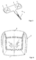
- the embodiments of the pressure sensor 1, which in the Figures 2 and 3 are each shown having two first sensor elements 2 and two second sensor elements 3, while the embodiment of the FIG. 4 four first sensor elements 2 and two second sensor elements 3 includes.
- the embodiment, as in FIG. 5 is shown, however, has a total of five sensor elements, which are composed of three first sensor elements 2 and two second sensor elements 3.
- first sensor elements 2 each have a first triggering sensitivity by a first switching threshold S 1 exerted by pressure, and that the second sensor elements 3 have a second triggering sensitivity by a second switching threshold S 2 exerted by pressure.
- the first triggering sensitivity is higher than the second triggering sensitivity and accordingly the first switching threshold S 1 is lower than the second switching threshold S 2 .
- An occupancy detection device which comprises, for example, in the simplest construction, only a first sensor element 2 and only a second sensor element 3, operates in a manner which is described in US Pat FIG. 1 is shown.
- the force F is plotted on the horizontal axis in the diagram and the occupancy states "0" (for not occupied) and "1" (for occupied) are plotted on the vertical axis.
- the first sensor element 2 and the second sensor element 3 are in the switching state "0".
- the switching threshold S 1 of the first sensor element 2 is reached, without this having a consequence on the change of the state "unoccupied”.
- the force exerted on the pressure sensor 1 force F increases until the switching threshold S 2 of the second sensor element 3 is reached.
- the achievement of the second switching threshold S 2 triggers a trigger signal, so that the switching state of the pressure sensor 1 to the value "1", which means "occupied” is set. If the force exerted by the weight of the person increases even further, this has no further effect on the now set to "1" switching state.
- the switching state "1" is maintained even if the switching threshold S 2 of the second sensor element is fallen short of. Only when the person leaves the seat, for example, gets out of the vehicle, the force F, which corresponds to the switching threshold S 1 of the first sensor element 2, reached or fallen below, whereby the seat occupancy indicating state is reset to the state "0".
- a set or reset can be done for example by a flip-flop.
- a check or assignment of the interconnected sensor elements can be realized via various discrete or printed components on the pressure sensor.
- this pressure sensor 1 it is ensured that an occupancy state is only reset to a non-occupancy state if the switching threshold S 1 of the sensor element 2 is again undershot with the high sensitivity.
- a time delay of 0.02 to 2 seconds can be set for the reset of the occupancy state to "0" , preferably from 0.3 to 1 second.
- pressure sensors 1 preferably foil pressure sensors are used, as they are also in the FIGS. 2 to 5 are shown.
- the pressure sensor 1 of FIG. 2 comprises a total of four sensor elements 2, 3, which are each combined into two groups with two sensor elements. While the one group comprises two first sensor elements 2 with the high triggering sensitivity, the other group comprises two second sensor elements 3 with the low triggering sensitivity, namely a triggering sensitivity which is lower than that of the first sensor elements 2.
- the four sensor elements 2, 3 are also in two sensor groups, as in FIG. 3 shown, summarized. Only the arrangement of the sensor elements or the sensor groups on the pressure sensor is different from the FIG. 2 , Also, one sensor group has two first sensor elements 2 with the high triggering sensitivity and the other sensor group has two second sensor elements 3 with the low triggering sensitivity. Such an arrangement should be chosen to achieve an extension of the detection area.
- such a pressure sensor 1 as in the Figures 2 and 3 not more than two groups of sensor elements can.
- the positioning of the sensor elements on the pressure sensor depends on the type of seat or the seat structure in order to optimally detect the pressure or the force exerted by a person seated on the seat surface of the cushion core.
- the pressure sensors 1, in the Figures 2 and 3 are shown, have connecting lines 4, via which the pressure sensor 1 and the sensor elements are connected to an evaluation unit, not shown.
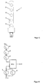
- FIG. 4 shows a plan view of a cushion core 5, on which a pressure sensor 1 is arranged.
- This pressure sensor 1 has six sensor elements 2, 3, which are divided into two groups, wherein the one group comprises four first sensor elements 2 and the other group comprises two second sensor elements 3.
- half of the sensor elements 2, 3 located in a sensor group is symmetrically positioned on both sides of an axis 6 and at a distance therefrom, which runs perpendicular to a surface which is spanned by the plane of a backrest associated with the seat surface; this level is in FIG. 4 denoted by the reference numeral 7.
- FIG. 5 shows the embodiment of a pressure sensor 1, in turn a film pressure sensor in which five sensor elements 2, 3 are each combined into two groups, in this case, one group, the sensor elements 2 and the other group, the sensor elements 3 respectively.
- the sensor elements 2, 3 are arranged longitudinally one behind the other on the pressure sensor.
- Such a pressure sensor 1 could be arranged along the axis 6 of a cushion core 5 of a seat, as shown in FIG. 4 is shown for the pressure sensor 1 shown there.
- the in FIG. 5 illustrated pressure sensor is also suitable for attachment between a cushion core and the cushion core receiving structure.
- three sensor elements are such sensor elements 2 with high triggering sensitivity and two sensor elements are those sensor elements 3 with low triggering sensitivity.
- the cushion core 5 like him FIG. 4 2
- the two sensor elements 3 with the low triggering sensitivity are further toward the position of the seat back (reference numeral 7), while the three sensor elements 2 with the high triggering sensitivity are positioned toward the front edge of the seat cushion 5.
- This positioning of the first and second sensor elements 2, 3 ensures that the condition "occupied” is always given as long as a person is in the seat during the driving operation, even if this person moves forward on the seat surface of the cushion core . sits down.
- FIG. 6 shows a circuit diagram for a pressure sensor, as shown in FIG. 5 is shown with three first sensor elements 2 with high tripping sensitivity and two second sensor elements 3 with low tripping sensitivity.
- This circuit is supplied with an operating voltage U B.
- the three first sensor elements 2 are connected in series, while the two second sensor elements 3 are connected in parallel.
- the sensor elements 2, 3 are divided into two groups, one group consisting of the sensor elements 2 and the other group consisting of the sensor elements 3. These two groups are connected separately to an evaluation unit and output a corresponding trigger signal to the evaluation unit.
- the state "occupied” is obtained at the output "A" of the evaluation unit when only one of the sensor elements 3 connected in parallel reaches its switching threshold, while the state “unoccupied” at the output "A” of the evaluation unit is present, if only one of the series-connected sensor elements 2 falls below its threshold.
- the trigger signal is fed to an evaluation unit ECU, which provides the output signal "A".
Landscapes
- Engineering & Computer Science (AREA)
- Mechanical Engineering (AREA)
- Aviation & Aerospace Engineering (AREA)
- Transportation (AREA)
- Seats For Vehicles (AREA)
Claims (10)
- Procédé pour détecter l'état d'occupation d'un siège présentant un dispositif de détection d'occupation comprenant au moins un capteur de pression (1), qui comporte au moins un premier élément de capteur (2) et au moins un deuxième élément de capteur (3), le capteur de pression (1) étant positionné entre un habillage de revêtement de siège et un noyau de rembourrage (5) et les éléments de capteur (2, 3) fournissant un signal de déclenchement correspondant, en fonction d'un état d'occupation du siège, et le dispositif de détection d'occupation comprenant également une unité de traitement de données, qui assure le traitement des signaux de déclenchement, caractérisé en ce qu'au premier élément de capteur (2) est associée une première sensibilité de déclenchement par un premier seuil de commutation (S1) exercé par une pression, et au deuxième élément de capteur est associée une deuxième sensibilité de déclenchement par un deuxième seuil de commutation (S2) exercé par une pression, et en ce que la première sensibilité de déclenchement est plus élevée que la deuxième sensibilité de déclenchement, le premier seuil de commutation (S1) étant donc plus bas que le deuxième seuil de commutation (S2), et le fait d'atteindre le deuxième seuil de commutation (S2) est pris en considération comme étant le signal de déclenchement pour un état d'occupation du siège et est transmis à l'unité de traitement de données pour y être traité, et cet état est réinitialisé seulement lorsque l'on passe à nouveau en-dessous du premier seuil de commutation (S1) dudit au moins un premier élément de capteur (2).
- Siège comprenant un dispositif de détection d'occupation pour la mise en oeuvre du procédé selon la revendication 1, pour détecter l'état d'occupation d'un siège présentant un dispositif de détection d'occupation comprenant au moins un capteur de pression (1), qui comporte au moins un premier élément de capteur (2) et au moins un deuxième élément de capteur (3), le capteur de pression (1) étant positionné entre un habillage de revêtement de siège et un noyau de rembourrage (5) et les éléments de capteur (2, 3) fournissant un signal de déclenchement correspondant, en fonction d'un état d'occupation du siège, et le dispositif de détection d'occupation comprenant également une unité de traitement de données, qui assure le traitement des signaux de déclenchement, caractérisé en ce que le premier élément de capteur (2) présente une première sensibilité de déclenchement par un premier seuil de commutation (S1) exercé par une pression, et le deuxième élément de capteur présente une deuxième sensibilité de déclenchement par un deuxième seuil de commutation (S2) exercé par une pression, et en ce que la première sensibilité de déclenchement est plus élevée que la deuxième sensibilité de déclenchement, le premier seuil de commutation (S1) étant donc plus bas que le deuxième seuil de commutation (S2), et le fait d'atteindre le deuxième seuil de commutation (S2) est pris en considération comme étant le signal de déclenchement pour un état d'occupation du siège et est transmis à l'unité de traitement de données pour y être traité, et cet état est réinitialisé seulement lorsque l'on passe à nouveau en-dessous du premier seuil de commutation (S1) dudit au moins un premier élément de capteur (2).
- Siège selon la revendication 2, caractérisé en ce que ledit au moins un capteur de pression (1) comprend au moins deux premiers éléments de capteur (2) séparés spatialement et/ou au moins deux deuxièmes éléments de capteur (3) séparés spatialement, aussi bien les premiers que les deuxièmes éléments de capteur (2, 3) étant respectivement commutés électriquement en groupes de capteurs.
- Siège selon la revendication 3, caractérisé en ce que chaque groupe de capteurs est constitué de deux éléments de capteur (2; 3).
- Siège selon l'une des revendications 2 à 4, caractérisé en ce que sont prévus plusieurs premiers éléments de capteur (2), et ces premiers éléments de capteur (2) sont montés en série.
- Siège selon l'une des revendications 2 à 5, caractérisé en ce que le capteur de pression (1) fournit au moins un signal de sortie dudit au moins un premier élément de capteur (2) et au moins un signal de sortie dudit au moins un deuxième élément de capteur (3), pour une unité de traitement de données spatialement séparée.
- Siège selon l'une des revendications 2 à 5, caractérisé en ce que l'unité de traitement de données est agencée sur le capteur de pression (1).
- Siège selon l'une des revendications 3 à 5, caractérisé en ce que les éléments de capteur (2; 3) sont agencés le long d'un axe (6), qui s'étend perpendiculairement à une surface (7) formée par le plan d'un dossier associé à la surface d'assise.
- Siège selon l'une des revendications 3 à 8, caractérisé en ce qu'au maximum sont prévus cinq éléments de capteur (2; 3), le nombre des premiers éléments de capteur (2) étant supérieur au nombre des deuxièmes éléments de capteur (3).
- Siège selon l'une des revendications 2 à 9, caractérisé en ce que le capteur de pression (1) est un capteur de pression sous forme de film ou de feuille.
Applications Claiming Priority (1)
| Application Number | Priority Date | Filing Date | Title |
|---|---|---|---|
| DE202011102827U DE202011102827U1 (de) | 2011-06-15 | 2011-06-15 | Belegungserfassungseinrichtung |
Publications (3)
| Publication Number | Publication Date |
|---|---|
| EP2535227A1 EP2535227A1 (fr) | 2012-12-19 |
| EP2535227B1 true EP2535227B1 (fr) | 2016-02-24 |
| EP2535227B8 EP2535227B8 (fr) | 2016-05-18 |
Family
ID=46168102
Family Applications (1)
| Application Number | Title | Priority Date | Filing Date |
|---|---|---|---|
| EP12003629.8A Active EP2535227B8 (fr) | 2011-06-15 | 2012-05-09 | Procédé de détection de l'occupation d'un siège et siège avec un dispositif de détection d'occupation |
Country Status (2)
| Country | Link |
|---|---|
| EP (1) | EP2535227B8 (fr) |
| DE (1) | DE202011102827U1 (fr) |
Families Citing this family (4)
| Publication number | Priority date | Publication date | Assignee | Title |
|---|---|---|---|---|
| JP6828382B2 (ja) * | 2015-12-11 | 2021-02-10 | アイシン精機株式会社 | 着座検知装置 |
| JP6744570B2 (ja) | 2016-06-17 | 2020-08-19 | アイシン精機株式会社 | 着座検知装置 |
| CN110553572B (zh) * | 2018-05-30 | 2024-06-28 | 泰科电子(上海)有限公司 | 用于车辆刹车踏板的传感装置、用于车辆刹车踏板的传感器及感测方法 |
| DE102024115782A1 (de) * | 2024-06-06 | 2025-12-11 | Dr. Ing. H.C. F. Porsche Aktiengesellschaft | Belegungserfassungseinrichtung zum Detektieren des Belegungszustands eines Sitzes |
Family Cites Families (4)
| Publication number | Priority date | Publication date | Assignee | Title |
|---|---|---|---|---|
| JP2004034918A (ja) * | 2002-07-08 | 2004-02-05 | Honda Motor Co Ltd | エアバッグの展開制御装置 |
| EP1492136A1 (fr) * | 2003-06-23 | 2004-12-29 | IEE International Electronics & Engineering S.A.R.L. | Capteur de pression du type à feuilles |
| DE202005000018U1 (de) | 2005-01-03 | 2005-03-24 | Iee Sarl | Sensormatte mit zwei Schaltniveaus |
| JP5103027B2 (ja) | 2007-01-29 | 2012-12-19 | トヨタ紡織株式会社 | 車両用シート |
-
2011
- 2011-06-15 DE DE202011102827U patent/DE202011102827U1/de not_active Expired - Lifetime
-
2012
- 2012-05-09 EP EP12003629.8A patent/EP2535227B8/fr active Active
Also Published As
| Publication number | Publication date |
|---|---|
| EP2535227B8 (fr) | 2016-05-18 |
| DE202011102827U1 (de) | 2012-09-19 |
| EP2535227A1 (fr) | 2012-12-19 |
Similar Documents
| Publication | Publication Date | Title |
|---|---|---|
| DE69707906T2 (de) | Verfahren und Vorrichtung zur Bestimmung von verschiedenen Parametern einer auf einen Sitz sitzenden Person | |
| EP1636071B1 (fr) | Capteur permettant de detecter l'occupation d'un siege | |
| DE4406897C1 (de) | Vorrichtung zur Sitzbelegungserkennung für ein Kraftfahrzeug | |
| DE102007062764B4 (de) | System und Verfahren zum Klassifizieren von Fahrzeuginsassen | |
| DE10007014C2 (de) | Verfahren und Vorrichtung zur Sitzbelegungserkennung | |
| DE10233098C1 (de) | Verfahren und Anordnung bei der Klassifizierung von einen Sitz belegenden Objekten | |
| EP0891898B1 (fr) | Méthode et appareillage d' enregistrement de différents paramètres d' une personne assise sur un support | |
| EP1497161B1 (fr) | Procede de detection de l'occupation d'un siege de vehicule | |
| EP2535227B1 (fr) | Procédé de détection de l'occupation d'un siège et siège avec un dispositif de détection d'occupation | |
| DE69602539T2 (de) | Detektor für fahrzeugsitze | |
| DE102011106521B4 (de) | Belegungserfassungseinrichtung | |
| DE102015222715B4 (de) | Vorrichtung und Verfahren zur Erfassung von Benutzereingaben zur Einstellung eines Sitzplatzes | |
| EP1833702B1 (fr) | Tapis de detection comprenant deux niveau de commutation | |
| EP1000797B1 (fr) | Dispositif et méthode pour reconnaitre le type d'occupation d'un siège de véhicule | |
| EP1491408A1 (fr) | Détecteur d'occupation de siège | |
| WO2006131483A1 (fr) | Dispositif et procede pour detecter l'occupation d'un siege | |
| DE102004015408B4 (de) | Sitzbelegungsdrucksensor | |
| DE10335734A1 (de) | Verfahren zur Sitzbelegungserkennung für ein Kraftfahrzeug | |
| EP1765643B1 (fr) | Systeme pour determiner l'occupation d'un siege de vehicule a moteur | |
| DE102005014526A1 (de) | Vorrichtung und Verfahren zum Unterscheiden einer Person von einem Gegenstand auf einem Fahrzeugsitz | |
| DE102007043454A1 (de) | Modulare Sitzgurt-Erinnerungseinrichtung | |
| DE102006056920B4 (de) | Sensoreinrichtung für den Sitz eines Transportmittels | |
| DE112015001310T5 (de) | Sitzbelegungssensor | |
| DE102024115782A1 (de) | Belegungserfassungseinrichtung zum Detektieren des Belegungszustands eines Sitzes | |
| EP4506209A1 (fr) | Siege de vehicule |
Legal Events
| Date | Code | Title | Description |
|---|---|---|---|
| PUAI | Public reference made under article 153(3) epc to a published international application that has entered the european phase |
Free format text: ORIGINAL CODE: 0009012 |
|
| AK | Designated contracting states |
Kind code of ref document: A1 Designated state(s): AL AT BE BG CH CY CZ DE DK EE ES FI FR GB GR HR HU IE IS IT LI LT LU LV MC MK MT NL NO PL PT RO RS SE SI SK SM TR |
|
| AX | Request for extension of the european patent |
Extension state: BA ME |
|
| 17P | Request for examination filed |
Effective date: 20130619 |
|
| RBV | Designated contracting states (corrected) |
Designated state(s): AL AT BE BG CH CY CZ DE DK EE ES FI FR GB GR HR HU IE IS IT LI LT LU LV MC MK MT NL NO PL PT RO RS SE SI SK SM TR |
|
| 17Q | First examination report despatched |
Effective date: 20140613 |
|
| GRAP | Despatch of communication of intention to grant a patent |
Free format text: ORIGINAL CODE: EPIDOSNIGR1 |
|
| INTG | Intention to grant announced |
Effective date: 20151016 |
|
| REG | Reference to a national code |
Ref country code: DE Ref legal event code: R108 Ref document number: 502012006017 Country of ref document: DE |
|
| GRAS | Grant fee paid |
Free format text: ORIGINAL CODE: EPIDOSNIGR3 |
|
| GRAA | (expected) grant |
Free format text: ORIGINAL CODE: 0009210 |
|
| AK | Designated contracting states |
Kind code of ref document: B1 Designated state(s): AL AT BE BG CH CY CZ DE DK EE ES FI FR GB GR HR HU IE IS IT LI LT LU LV MC MK MT NL NO PL PT RO RS SE SI SK SM TR |
|
| REG | Reference to a national code |
Ref country code: GB Ref legal event code: FG4D Free format text: NOT ENGLISH |
|
| REG | Reference to a national code |
Ref country code: CH Ref legal event code: EP |
|
| REG | Reference to a national code |
Ref country code: AT Ref legal event code: REF Ref document number: 776511 Country of ref document: AT Kind code of ref document: T Effective date: 20160315 |
|
| REG | Reference to a national code |
Ref country code: IE Ref legal event code: FG4D Free format text: LANGUAGE OF EP DOCUMENT: GERMAN |
|
| REG | Reference to a national code |
Ref country code: DE Ref legal event code: R096 Ref document number: 502012006017 Country of ref document: DE |
|
| RBV | Designated contracting states (corrected) |
Designated state(s): AL AT BE BG CH CY CZ DE DK EE ES FI FR GB GR HR HU IE IS IT LI LT LU LV MC MK MT NL NO PL PT RO RS SE SI SK SM TR |
|
| RBV | Designated contracting states (corrected) |
Designated state(s): AL AT BE BG CH CY CZ DK EE ES FI FR GB GR HR HU IE IS IT LI LT LU LV MC MK MT NL NO PL PT RO RS SE SI SK SM TR |
|
| REG | Reference to a national code |
Ref country code: FR Ref legal event code: PLFP Year of fee payment: 5 |
|
| REG | Reference to a national code |
Ref country code: DE Ref legal event code: R107 Ref document number: 502012006017 Country of ref document: DE |
|
| REG | Reference to a national code |
Ref country code: LT Ref legal event code: MG4D |
|
| REG | Reference to a national code |
Ref country code: NL Ref legal event code: MP Effective date: 20160224 |
|
| PG25 | Lapsed in a contracting state [announced via postgrant information from national office to epo] |
Ref country code: GR Free format text: LAPSE BECAUSE OF FAILURE TO SUBMIT A TRANSLATION OF THE DESCRIPTION OR TO PAY THE FEE WITHIN THE PRESCRIBED TIME-LIMIT Effective date: 20160525 Ref country code: FI Free format text: LAPSE BECAUSE OF FAILURE TO SUBMIT A TRANSLATION OF THE DESCRIPTION OR TO PAY THE FEE WITHIN THE PRESCRIBED TIME-LIMIT Effective date: 20160224 Ref country code: IT Free format text: LAPSE BECAUSE OF FAILURE TO SUBMIT A TRANSLATION OF THE DESCRIPTION OR TO PAY THE FEE WITHIN THE PRESCRIBED TIME-LIMIT Effective date: 20160224 Ref country code: NO Free format text: LAPSE BECAUSE OF FAILURE TO SUBMIT A TRANSLATION OF THE DESCRIPTION OR TO PAY THE FEE WITHIN THE PRESCRIBED TIME-LIMIT Effective date: 20160524 Ref country code: HR Free format text: LAPSE BECAUSE OF FAILURE TO SUBMIT A TRANSLATION OF THE DESCRIPTION OR TO PAY THE FEE WITHIN THE PRESCRIBED TIME-LIMIT Effective date: 20160224 Ref country code: ES Free format text: LAPSE BECAUSE OF FAILURE TO SUBMIT A TRANSLATION OF THE DESCRIPTION OR TO PAY THE FEE WITHIN THE PRESCRIBED TIME-LIMIT Effective date: 20160224 |
|
| PG25 | Lapsed in a contracting state [announced via postgrant information from national office to epo] |
Ref country code: PT Free format text: LAPSE BECAUSE OF FAILURE TO SUBMIT A TRANSLATION OF THE DESCRIPTION OR TO PAY THE FEE WITHIN THE PRESCRIBED TIME-LIMIT Effective date: 20160624 Ref country code: RS Free format text: LAPSE BECAUSE OF FAILURE TO SUBMIT A TRANSLATION OF THE DESCRIPTION OR TO PAY THE FEE WITHIN THE PRESCRIBED TIME-LIMIT Effective date: 20160224 Ref country code: NL Free format text: LAPSE BECAUSE OF FAILURE TO SUBMIT A TRANSLATION OF THE DESCRIPTION OR TO PAY THE FEE WITHIN THE PRESCRIBED TIME-LIMIT Effective date: 20160224 Ref country code: SE Free format text: LAPSE BECAUSE OF FAILURE TO SUBMIT A TRANSLATION OF THE DESCRIPTION OR TO PAY THE FEE WITHIN THE PRESCRIBED TIME-LIMIT Effective date: 20160224 Ref country code: LV Free format text: LAPSE BECAUSE OF FAILURE TO SUBMIT A TRANSLATION OF THE DESCRIPTION OR TO PAY THE FEE WITHIN THE PRESCRIBED TIME-LIMIT Effective date: 20160224 Ref country code: PL Free format text: LAPSE BECAUSE OF FAILURE TO SUBMIT A TRANSLATION OF THE DESCRIPTION OR TO PAY THE FEE WITHIN THE PRESCRIBED TIME-LIMIT Effective date: 20160224 Ref country code: BE Free format text: LAPSE BECAUSE OF NON-PAYMENT OF DUE FEES Effective date: 20160531 Ref country code: LT Free format text: LAPSE BECAUSE OF FAILURE TO SUBMIT A TRANSLATION OF THE DESCRIPTION OR TO PAY THE FEE WITHIN THE PRESCRIBED TIME-LIMIT Effective date: 20160224 |
|
| REG | Reference to a national code |
Ref country code: SK Ref legal event code: T3 Ref document number: E 20923 Country of ref document: SK |
|
| PG25 | Lapsed in a contracting state [announced via postgrant information from national office to epo] |
Ref country code: DK Free format text: LAPSE BECAUSE OF FAILURE TO SUBMIT A TRANSLATION OF THE DESCRIPTION OR TO PAY THE FEE WITHIN THE PRESCRIBED TIME-LIMIT Effective date: 20160224 Ref country code: EE Free format text: LAPSE BECAUSE OF FAILURE TO SUBMIT A TRANSLATION OF THE DESCRIPTION OR TO PAY THE FEE WITHIN THE PRESCRIBED TIME-LIMIT Effective date: 20160224 |
|
| PG25 | Lapsed in a contracting state [announced via postgrant information from national office to epo] |
Ref country code: RO Free format text: LAPSE BECAUSE OF FAILURE TO SUBMIT A TRANSLATION OF THE DESCRIPTION OR TO PAY THE FEE WITHIN THE PRESCRIBED TIME-LIMIT Effective date: 20160224 Ref country code: SM Free format text: LAPSE BECAUSE OF FAILURE TO SUBMIT A TRANSLATION OF THE DESCRIPTION OR TO PAY THE FEE WITHIN THE PRESCRIBED TIME-LIMIT Effective date: 20160224 Ref country code: CZ Free format text: LAPSE BECAUSE OF FAILURE TO SUBMIT A TRANSLATION OF THE DESCRIPTION OR TO PAY THE FEE WITHIN THE PRESCRIBED TIME-LIMIT Effective date: 20160224 |
|
| PLBE | No opposition filed within time limit |
Free format text: ORIGINAL CODE: 0009261 |
|
| REG | Reference to a national code |
Ref country code: CH Ref legal event code: PL |
|
| STAA | Information on the status of an ep patent application or granted ep patent |
Free format text: STATUS: NO OPPOSITION FILED WITHIN TIME LIMIT |
|
| GBPC | Gb: european patent ceased through non-payment of renewal fee |
Effective date: 20160524 |
|
| PG25 | Lapsed in a contracting state [announced via postgrant information from national office to epo] |
Ref country code: LI Free format text: LAPSE BECAUSE OF NON-PAYMENT OF DUE FEES Effective date: 20160531 Ref country code: CH Free format text: LAPSE BECAUSE OF NON-PAYMENT OF DUE FEES Effective date: 20160531 |
|
| 26N | No opposition filed |
Effective date: 20161125 |
|
| REG | Reference to a national code |
Ref country code: IE Ref legal event code: MM4A |
|
| PG25 | Lapsed in a contracting state [announced via postgrant information from national office to epo] |
Ref country code: SI Free format text: LAPSE BECAUSE OF FAILURE TO SUBMIT A TRANSLATION OF THE DESCRIPTION OR TO PAY THE FEE WITHIN THE PRESCRIBED TIME-LIMIT Effective date: 20160224 Ref country code: BG Free format text: LAPSE BECAUSE OF FAILURE TO SUBMIT A TRANSLATION OF THE DESCRIPTION OR TO PAY THE FEE WITHIN THE PRESCRIBED TIME-LIMIT Effective date: 20160524 |
|
| REG | Reference to a national code |
Ref country code: FR Ref legal event code: PLFP Year of fee payment: 6 |
|
| PG25 | Lapsed in a contracting state [announced via postgrant information from national office to epo] |
Ref country code: IE Free format text: LAPSE BECAUSE OF NON-PAYMENT OF DUE FEES Effective date: 20160509 Ref country code: GB Free format text: LAPSE BECAUSE OF NON-PAYMENT OF DUE FEES Effective date: 20160524 |
|
| REG | Reference to a national code |
Ref country code: FR Ref legal event code: PLFP Year of fee payment: 7 |
|
| PG25 | Lapsed in a contracting state [announced via postgrant information from national office to epo] |
Ref country code: CY Free format text: LAPSE BECAUSE OF FAILURE TO SUBMIT A TRANSLATION OF THE DESCRIPTION OR TO PAY THE FEE WITHIN THE PRESCRIBED TIME-LIMIT Effective date: 20160224 Ref country code: HU Free format text: LAPSE BECAUSE OF FAILURE TO SUBMIT A TRANSLATION OF THE DESCRIPTION OR TO PAY THE FEE WITHIN THE PRESCRIBED TIME-LIMIT; INVALID AB INITIO Effective date: 20120509 |
|
| PG25 | Lapsed in a contracting state [announced via postgrant information from national office to epo] |
Ref country code: MK Free format text: LAPSE BECAUSE OF FAILURE TO SUBMIT A TRANSLATION OF THE DESCRIPTION OR TO PAY THE FEE WITHIN THE PRESCRIBED TIME-LIMIT Effective date: 20160224 Ref country code: MC Free format text: LAPSE BECAUSE OF FAILURE TO SUBMIT A TRANSLATION OF THE DESCRIPTION OR TO PAY THE FEE WITHIN THE PRESCRIBED TIME-LIMIT Effective date: 20160224 Ref country code: TR Free format text: LAPSE BECAUSE OF FAILURE TO SUBMIT A TRANSLATION OF THE DESCRIPTION OR TO PAY THE FEE WITHIN THE PRESCRIBED TIME-LIMIT Effective date: 20160224 Ref country code: MT Free format text: LAPSE BECAUSE OF FAILURE TO SUBMIT A TRANSLATION OF THE DESCRIPTION OR TO PAY THE FEE WITHIN THE PRESCRIBED TIME-LIMIT Effective date: 20160224 Ref country code: IS Free format text: LAPSE BECAUSE OF FAILURE TO SUBMIT A TRANSLATION OF THE DESCRIPTION OR TO PAY THE FEE WITHIN THE PRESCRIBED TIME-LIMIT Effective date: 20160224 |
|
| REG | Reference to a national code |
Ref country code: AT Ref legal event code: MM01 Ref document number: 776511 Country of ref document: AT Kind code of ref document: T Effective date: 20170509 |
|
| PG25 | Lapsed in a contracting state [announced via postgrant information from national office to epo] |
Ref country code: AT Free format text: LAPSE BECAUSE OF NON-PAYMENT OF DUE FEES Effective date: 20170509 |
|
| PG25 | Lapsed in a contracting state [announced via postgrant information from national office to epo] |
Ref country code: AL Free format text: LAPSE BECAUSE OF FAILURE TO SUBMIT A TRANSLATION OF THE DESCRIPTION OR TO PAY THE FEE WITHIN THE PRESCRIBED TIME-LIMIT Effective date: 20160224 |
|
| PGFP | Annual fee paid to national office [announced via postgrant information from national office to epo] |
Ref country code: LU Payment date: 20240527 Year of fee payment: 13 |
|
| PGFP | Annual fee paid to national office [announced via postgrant information from national office to epo] |
Ref country code: SK Payment date: 20240422 Year of fee payment: 13 |
|
| PGFP | Annual fee paid to national office [announced via postgrant information from national office to epo] |
Ref country code: FR Payment date: 20250526 Year of fee payment: 14 |
|
| REG | Reference to a national code |
Ref country code: SK Ref legal event code: MM4A Ref document number: E 20923 Country of ref document: SK Effective date: 20250509 |
|
| PG25 | Lapsed in a contracting state [announced via postgrant information from national office to epo] |
Ref country code: LU Free format text: LAPSE BECAUSE OF NON-PAYMENT OF DUE FEES Effective date: 20250509 |
|
| PG25 | Lapsed in a contracting state [announced via postgrant information from national office to epo] |
Ref country code: SK Free format text: LAPSE BECAUSE OF NON-PAYMENT OF DUE FEES Effective date: 20250509 |