EP2536463B1 - Set aus einfach zu reinigenden steckverbindern für einen flüssigkeitskreislauf - Google Patents
Set aus einfach zu reinigenden steckverbindern für einen flüssigkeitskreislauf Download PDFInfo
- Publication number
- EP2536463B1 EP2536463B1 EP11703897.6A EP11703897A EP2536463B1 EP 2536463 B1 EP2536463 B1 EP 2536463B1 EP 11703897 A EP11703897 A EP 11703897A EP 2536463 B1 EP2536463 B1 EP 2536463B1
- Authority
- EP
- European Patent Office
- Prior art keywords
- connector
- distal
- male
- membrane
- female
- Prior art date
- Legal status (The legal status is an assumption and is not a legal conclusion. Google has not performed a legal analysis and makes no representation as to the accuracy of the status listed.)
- Active
Links
Images


Classifications
-
- A—HUMAN NECESSITIES
- A61—MEDICAL OR VETERINARY SCIENCE; HYGIENE
- A61M—DEVICES FOR INTRODUCING MEDIA INTO, OR ONTO, THE BODY; DEVICES FOR TRANSDUCING BODY MEDIA OR FOR TAKING MEDIA FROM THE BODY; DEVICES FOR PRODUCING OR ENDING SLEEP OR STUPOR
- A61M39/00—Tubes, tube connectors, tube couplings, valves, access sites or the like, specially adapted for medical use
- A61M39/22—Valves or arrangement of valves
- A61M39/26—Valves closing automatically on disconnecting the line and opening on reconnection thereof
-
- A—HUMAN NECESSITIES
- A61—MEDICAL OR VETERINARY SCIENCE; HYGIENE
- A61M—DEVICES FOR INTRODUCING MEDIA INTO, OR ONTO, THE BODY; DEVICES FOR TRANSDUCING BODY MEDIA OR FOR TAKING MEDIA FROM THE BODY; DEVICES FOR PRODUCING OR ENDING SLEEP OR STUPOR
- A61M39/00—Tubes, tube connectors, tube couplings, valves, access sites or the like, specially adapted for medical use
- A61M39/10—Tube connectors; Tube couplings
- A61M39/1011—Locking means for securing connection; Additional tamper safeties
-
- A—HUMAN NECESSITIES
- A61—MEDICAL OR VETERINARY SCIENCE; HYGIENE
- A61M—DEVICES FOR INTRODUCING MEDIA INTO, OR ONTO, THE BODY; DEVICES FOR TRANSDUCING BODY MEDIA OR FOR TAKING MEDIA FROM THE BODY; DEVICES FOR PRODUCING OR ENDING SLEEP OR STUPOR
- A61M39/00—Tubes, tube connectors, tube couplings, valves, access sites or the like, specially adapted for medical use
- A61M39/22—Valves or arrangement of valves
- A61M39/26—Valves closing automatically on disconnecting the line and opening on reconnection thereof
- A61M2039/267—Valves closing automatically on disconnecting the line and opening on reconnection thereof having a sealing sleeve around a tubular or solid stem portion of the connector
Definitions
- the invention relates to a connector for a liquid circuit, in particular for medical use.
- a connector for a liquid circuit in particular for medical use, comprising a proximal connection, a distal connection defining a passage, a hollow tube mounted fixed on the proximal connection, extending in the passage of the distal connection and comprising a free end distal, and an elastically deformable membrane, substantially tubular, closed at a distal end by a thickness of membrane and intended to cover the free end of the hollow tube in a substantially airtight manner at rest, the distal connector being mounted to slide relative to the connector proximal between a distal rest position and a proximal position of use in which the hollow tube can be selectively disengaged from said thickness of membrane.
- the Applicant has realized that the male and female connectors were difficult to clean, in particular at the level of their respective distal parts comprising the membrane.
- the cleanliness of the equipment used is fundamental insofar as patients are very susceptible to diseases nosocomiales.
- connection and disconnection of the connector assembly is difficult and requires several steps on the part of the operator.
- the current locking means do not guarantee the user that the connectors are actually well connected.
- the operator often cannot know if he has sufficiently screwed the connectors together and if the connection of the tubes is correctly carried out.
- the document WO 2006/076656 describes a first fluid connector capable of connecting to a second fluid connector for transferring fluids.
- the first connector has a passage for fluids, an inner element and an outer ring disposed around the inner element and which can optionally move forward or backward relative to it.
- the outer ring can be moved to clean the inner element.
- a distal part of the inner element can be almost closed when the first and second fittings are disconnected.
- connection assembly which can be disconnected either manually or automatically by the application of a sufficiently weak axial force to avoid injuring the patient.
- This connection assembly includes a male connector and a female connector, each comprising a penetration tube, mounted in a housing, and a membrane.
- the male connector and the female connector further include associated latching means in order to connect their respective housings.
- the document FR 2 931 363 in the name of the Applicant, describes a connector for a liquid circuit comprising a proximal connection, a distal connection defining a passage, a hollow tube mounted fixed on the proximal connection, extending in the passage of the distal connection and comprising one end distal free, and an elastically deformable membrane, substantially tubular, closed at a distal end by a thickness of membrane and intended to cover the free end of the hollow tube in a substantially airtight manner at rest.
- the distal connector is slidably mounted relative to the proximal connector between a distal rest position and a proximal position of use in which the hollow tube can be selectively disengaged from said thickness of membrane.
- the document WO 2006/078355 describes a connector assembly comprising a male Luer connector and a female Luer connector.
- the male connector has two internal valves and a vacuum generating structure configured to return any fluid remaining on the interface between the connectors to the male connector during disconnection and to seal the distal end of the male connector.
- An elastic member urges the male valves towards the closed position and includes a variable internal volume which creates a vacuum when the connectors are separated.
- the male valves are adjusted to a specific sequence corresponding to the closing of a safety valve. internal female connector so that the vacuum generated by the male connector has the greatest fluid booster effect.
- a Luer fitting comprising a housing having a first end provided with a male Luer end piece and a second end.
- the connector further includes a rigid shutter member having a first open end and a second closed end, as well as a retaining member adapted to couple the shutter member and the housing.
- the housing further comprises a rigid conduit placed inside the housing and being in fluid communication with the second end of the housing, this rigid conduit being adapted to engage with the first open end of the shutter element.
- the housing contains a first internal volume when the shutter element is in a first position and a second volume, smaller than the first, when the shutter element is in a second position.
- the invention therefore aims to provide an improved male and female connection.
- the invention provides a secure connection assembly for a liquid circuit according to claim 1.
- a set of at least two connectors in accordance with the above, intended to cooperate together to produce a circuit of fluids, in particular in the medical field, exhibits the fact that the locking means of one of the connectors is male, and the locking means of the other of the connectors is female.
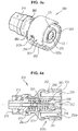
- the female connector 100 comprises a proximal connector 120, an elastically deformable membrane, substantially tubular, and a distal connector 140.
- the proximal connector 120 is generally tubular in shape and has a proximal end which here comprises a connectable inlet 121 of the female "Luer-Lock” type.
- this connectable input 121 is of the male "Luer-Lock” type. It is extended, in the distal direction, by a hollow body 122 which comprises, in the vicinity of the proximal end, an annular bulge 126 projecting and extending over a radially external circumference of the hollow body 122 of the proximal connector 120 , intended to cooperate with a complementary annular groove 142 provided on the distal connector 140, in order to block in translation the proximal 120 and distal 140 connectors relative to each other, as we will see below.
- the hollow body 122 of the proximal connector 120 terminates, in the distal direction, by a rim 123, of circular shape, surmounted coaxially by a hollow tube 124 which projects from the proximal connector 120 in the distal direction.
- the hollow tube 124 ends with a free distal end 125.
- the hollow tube forms a connecting member.
- the distal connector 140 is tubular in shape and defines a passage 141.
- the proximal connector 120 comprises at least one pin, preferably two, which cooperate with as many orifices provided on the distal connector 140.
- This membrane 130 comprises elastic means 131, here a spring 131, for example of the helical compression spring type, forming a membrane body, extending to a distal end 132 closed by a thickness of membrane.
- elastic means 131 are intended to bear on the proximal connector 120 and to push the distal end 132 of the membrane so that the latter comes into a stable downstream position for closing a distal end of the passage 141 .
- the body of the membrane 130 is corrugated, and is in the form of a bellows.
- a slot 133 is made passing through said thickness of membrane.
- the distal end 132 of the membrane 130 has a groove intended to receive a reinforcement / necking means 134, here being in the form of a cup, which surrounds the slot 133 and allows d 'Ensure, in the rest position, that it is closed in leaktight manner to avoid possible losses of pressurized fluids which may be present in the hollow tube 124 when using the connector 100 mounted on a fluid circuit.
- a reinforcement / necking means 134 here being in the form of a cup
- the particular shape of the body 131 of membrane 130 allows the latter to be able to deform elastically in a longitudinal direction and to act as a return spring allowing the membrane 130 to return to its initial shape of rest, such that 'illustrated on Figures 1 and 2 , when the connector 100 is disconnected.
- the female connector 100 comprises a membrane 130 which is encapsulated in the tubular part of the distal connector 140. This also allows, in the stable downstream shutter position, radial tightening of the membrane 130, and in particular of the end distal 132 of the latter, produced by a wall of the tubular part of the distal connector 140: better sealing and improved resistance to back pressure are then obtained.
- the membrane 130 is made of an elastomeric material, such as polyisoprene, silicone, or else an elastomeric thermoplastic (TPE).
- elastomeric material such as polyisoprene, silicone, or else an elastomeric thermoplastic (TPE).
- the spring 131 forming the body of the membrane 130 is threaded onto the hollow tube 124 of the proximal connector 120.
- the distal connector 140 On its periphery, preferably in the proximal part, the distal connector 140 comprises a locking means 150 male or female. This locking means 150 will be detailed later in the description.
- the distal connector 140 furthermore comprises means of manipulation 143 of the connector 100. Here there are two of them and extend radially projecting in a centrifugal manner on either side of the distal connector 140. These manipulation means 143 allow the connector 100 to be held firmly when it is connected to a male connector.
- the distal connector 140 is mounted on the proximal connector 120 so that the annular projection 126 is positioned in the corresponding annular groove 142.
- the distal connector 140 is then fixed according to the usual methods on the proximal connector 120, for example by bonding their respective contact surfaces, so as to obtain a monobloc casing, or also by ultrasonic welding.
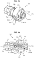
- a male connector 200 comprises a proximal connector 210 and a casing 220 mounted on the proximal connector 210.
- the assembly of the casing 220 on the proximal connector 210 makes it possible to delimit a substantially tubular chamber 211 forming a passage.
- the proximal connector 210 has a connectable inlet 212, here, of the male "Luer-Lock” type. In an alternative embodiment, this connectable input 212 is of the "female Luer-Lock" type.
- the connector 200 comprises a connection member 213, here in the form of a hollow tube 213, extending in the substantially tubular passage 211 in the distal direction.
- the housing 220 is formed by a distal connection 240 and comprises a tubular part.
- the proximal connection comprises a membrane or septum 230 which includes a slot 233 in its thickness.
- the slot 233 is substantially perpendicular to a longitudinal axis of the connector 200.
- the connector 200 finally comprises elastic means 231, here a spring 231, for example of the helical compression spring type, but which can also take any other form known to those skilled in the art.
- the spring 231 is intended to bear on the proximal connector 210 and to push the septum 230 so that the latter comes into a stable downstream position for closing a distal end of the passage 211.
- connector 200 A more detailed description of a connector similar to connector 200 is provided in the document EP 0 544 581 to which it is possible to refer for this purpose.
- the septum 230 is here an elastomeric membrane of generally cylindrical shape of revolution comprising a slot 233 substantially planar and perpendicular to a longitudinal axis of the septum 230.
- This slot 233 extends from a downstream surface into an upstream opening of substantially cylindrical shape. revolution intended to receive a free end of the hollow tube 214 in a sealed manner.
- the septum 230 is mounted in a rigid cup 234 forming reinforcement / necking means.
- this cup is surmounted by an elastically deformable ring, forming part of reinforcement / necking means.
- the male connector 200 comprises a septum (or membrane) 230 which is encapsulated in the tubular part of the distal connector 240.
- a septum (or membrane) 230 which is encapsulated in the tubular part of the distal connector 240. This allows, moreover, in the stable downstream shutter position radial tightening of the septum 230, and in particular level of the latter's slot 233, produced by a wall of the tubular part of the distal connector 240: better sealing and improved resistance to back pressure are then obtained.
- the distal connector 240 comprises a locking means 250 female or male.
- the female connector 100 comprises a male bayonet locking means
- the male connector 200 comprises a female bayonet locking means. This is in no way limiting, insofar as the embodiment consisting in providing a female locking means on the female connector 100 and a male locking means on the male connector 200 is equivalent and also covered by the invention .
- the locking means 250 of the male connector 200 is preferably complementary to the locking means 150 of the female connector 100.
- the locking means 250 when they are female, they are formed of a smooth surface 260 having an invariant axial section on a substantially continuous part of the distal connector 240, and of a retaining means 252 extending transversely. .
- the male locking means 150 then also consist of a smooth surface 160 and have a retaining means 151 extending transversely, of shapes complementary to the shapes of the smooth surface 260 and of the retaining means 252 of the female locking means 250 respectively .
- Such an embodiment therefore makes it possible to facilitate the cleaning of the locking means, insofar as it reduces the projecting edges on the surfaces 160, 260 to be cleaned, in contrast to the locking means by thread whose use is widespread in the world. prior art.
- the bayonet locking means by clipping (ie by elastic deformation of a retaining element projecting from the surface of the distal part of one of the means of locking, then penetration into a complementary orifice provided in the surface of the distal part of the other of the locking means, see for example figure 9 ), etc.
- the retaining means 151 of the male locking means comprises at least one lug extending transversely outward from the smooth external surface 260.
- the retaining means 151 comprises two pins, extending on either side of the distal connector 140 of the male connector 100.
- Each lug 151 may have a circular, square, elliptical section, or any other section adapted to effectively hold in position the male connector 100 relative to the female connector 200.
- the retaining means of the female locking means 250 meanwhile consists of at least one groove 252 formed in a surface 160 of a flange 251.
- the groove 252 can be through, so as to form a slot as illustrated in the appended figures, or blind.
- the flange 251 came integrally with the casing 220. In an alternative embodiment, it is attached to the casing, for example by bonding or welding or not any other means allowing such an assembly.
- the flange 251 is in the form of a tube connected, at a proximal end, by ribs 260 to the casing 220.
- passages 261 are arranged between the ribs 261.
- the ribs 260 are four in number and uniformly distributed over a circumference of the flange 251. Consequently, the passages are also four in number and uniformly distributed over said circumference of the flange 251.
- Such a structure allows optimal cleaning of the flange and therefore the male connector 200.
- the female locking means 250 comprises at least as many grooves 252 as there are lugs 151 on the male locking means 150.
- Each groove 252 preferably has a free end opening onto a distal end of the flange 251, the other end being closed and designed to form a longitudinal stop for the lug 151.
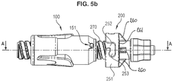
- grooves 252 are arranged on the flange 251 so that their respective free end is opposite a lug 151 when the distal ends 140, 240 of the male connectors 200 and female 100 are brought into contact before connection, as illustrated on the figure 5 .
- each lug 151 of the male locking means 150 enters a groove 252 of the female locking means 250 respectively.
- the central part 270 of the distal connector surrounded by the flange, is threaded so as to constitute a connectable inlet of the female Luer-Lock type.
- the distal part of the flange 251 is shortened so that the face of the central part 270 is accessible radially.
- the advantage of this embodiment is that it allows in particular the connection of the connector 200 with a syringe comprising a locking means of the Luer-Lock type.
- This embodiment also has the advantage of being easily cleanable insofar as the internal surface 260 of the flange 251 and the external surface 160 comprising the pins 151 are smooth, while the central threaded part 270 is directly accessible by a manipulator who wishes to clean it.
- the female locking means may comprise a flange comprising at least one lug protruding from its internal surface, complementary to a male locking means comprising a smooth external surface in which is formed a groove (not through).
- these embodiments make it possible to guarantee to the operator that the male connectors 200 and female 100 are actually well connected.
- the operator can visually and mechanically check whether the lug 151 is indeed at the bottom of the groove 252, which implies that the tubes 124 and 215 are effectively well connected, unlike conventional connectors comprising threaded locking means, which do not allow such checks.
- the length of a groove 252 is preferably at least equal to the maximum relative distance traveled by the connectors 100, 200 when they are connected by an operator. This relative distance will be further detailed later.
- the width of a groove 252 is substantially equal to the diameter of the corresponding lug 151, taken in the direction transverse to the direction of insertion of the lug 151 in the groove 252. In this way, the lug 151 can be move longitudinally in the groove 252 while being blocked transversely when it is inserted into the groove 252.
- the groove 252 is also bent in shape in order to keep the lug 151 fixed longitudinally when the latter comes into abutment.
- the groove 252 has a longitudinal part 252a, of length at least equal to the relative distance traveled by the connectors 100, 200 when they are connected, and a transverse part 252b, extending in a direction substantially perpendicular to the direction insertion of the pins 151.
- the angle formed between the transverse part 252b and the longitudinal part 252a of the groove 252 is acute, in order to accentuate the retention of the lug 151, and therefore the locking of all of the connectors 100, 200.
- the grooves 252 formed in a given flange 251 are identical. In particular, they are of identical size, shape and orientation, so that the pins 151 can easily penetrate into the groove 252 which is associated with them.
- the grooves 252 and associated lugs 151 can be of different widths two by two, so that a given lug 151 (having a given transverse diameter) cannot penetrate into a groove 252 having a smaller width, to ensure a keying function.
- each groove 252 is further provided with a recess or seat 253 disposed in the end of the groove 252 serving as a stop for the lug 151.
- the recess 253 is offset from the axis of the groove 252, in order to transversely block the lug 151 in the groove 252, and therefore to further improve the locking of the connector assembly 100, 200.
- the recess 253 is disposed in the closed end of the transverse part 252b of the groove 252 and is offset in the direction of the distal end relative to the axis of said transverse part 252.
- the figures 5 and 6 represent female 100 and male 200 connectors in a stable downstream closure position.
- the membrane 130 respectively 230, seals the passage 141, respectively 211, so that a downstream surface of the membrane 130, respectively, 230, is flush with the downstream end of said passage.
- a connector manipulator 100, 200 can easily clean said downstream surface of the membrane, in order to reduce the risks of nosocomial infections which could result from poor cleaning or difficult cleaning of this surface. .
- the back-pressure tightness is greatly increased, without destroying the performance in terms of repeated connections / disconnections.
- the use of rigid cups 134, 234 prevents any expulsion of the septa 130, 230 outside the connectors 100, 200 according to the invention under the effect of high pressures.
- the operator cleans the distal end of the membranes 130, 230 in order to remove any presence of germs or bacteria, as well as the bayonet locking means 150, 250 (and if necessary the part central 270).
- the operator brings the respective septums of the 200 male connector and the 100 female connector into contact, as illustrated in FIG. figure 5 , then connect the assembly.
- This connection between the connector 100 and the connector 200 is made by locking the lugs 151 of the distal connector 140 of the female connector 100 in the corresponding grooves 252 of the distal connector 240 of the male connector 200.
- the operator places the lugs 151 of the female connector 100 opposite the corresponding grooves 252, then slides the connectors 100, 200 relatively relative to each other by pushing the female connector 100, while resting on the manipulation means 143 of the distal connector 140, towards the male connector 200.
- the distal end of the male connector 200 pushes on the distal end of the membrane 130 of the female connector 100, which on the one hand forces the membrane body 131 to compress, and on the other hand , forces the distal end 125 of the hollow tube 124 to pass through the slit 133 through the thickness of membrane located at the distal end of the membrane 130.
- this distal end 125 of the tube 124 comes into bearing contact with the septum 230 of the connector 200.
- the distal end 125 of the tube 124 then pushes the septum 230, on the one hand, against the underlying spring 231 and , on the other hand, against the tube 214 which then passes through the septum 230 via the slot 233 which is formed there.
- the relative distance traveled by the connectors 100, 200 during handling is defined by the length of the longitudinal part 252a of the grooves 252.
- the pins 151 are therefore in abutment at the bottom of the longitudinal part 252a of the grooves 252.
- the operator Upon disconnection, the operator rotates the connectors 100, 200 relative to each other in the opposite direction to that of the locking, in order to remove the pins 151 from the transverse part 252b of the grooves 252, then discards the connectors 100, 200 with the help of the thrust of the two springs.
- the pins 151 then come out of the longitudinal part 252a of the grooves 252, the membranes 130, 230 again progressively cover the tubes 124, 214 respectively in a sealed manner and the membranes 130, 230 seal the respective distal ends of the connectors 100 , 200.
- sealing is ensured throughout the operation. Indeed, the seal is first ensured by the contact of the distal end of the membrane 130 on the septum 230, then by the contact of the distal end 125 of the hollow tube 124 on the septum 230 of the male connector 200 - said contact being maintained by locking the connector assembly - and finally by inserting the tube 214 into the hollow tube 125.
Landscapes
- Health & Medical Sciences (AREA)
- Heart & Thoracic Surgery (AREA)
- Pulmonology (AREA)
- Engineering & Computer Science (AREA)
- Anesthesiology (AREA)
- Biomedical Technology (AREA)
- Hematology (AREA)
- Life Sciences & Earth Sciences (AREA)
- Animal Behavior & Ethology (AREA)
- General Health & Medical Sciences (AREA)
- Public Health (AREA)
- Veterinary Medicine (AREA)
- Infusion, Injection, And Reservoir Apparatuses (AREA)
- Quick-Acting Or Multi-Walled Pipe Joints (AREA)
Claims (12)
- Sichere Verbindungsanordnung für einen Flüssigkeitskreislauf, umfassend:- einen männlichen Verbinder (200) und einen weiblichen Verbinder (100), die jeweils einen proximalen Anschluss (120, 210) und einen distalen Anschluss (140, 240) umfassen,- wobei der distale Anschluss (140, 240) jedes der Verbinder (100, 200) einen Durchlass (141, 211) definiert und einen rohrförmigen Abschnitt aufweist, in dem sich koaxial ein Verbindungsglied (124, 213), das an dem proximalen Anschluss (120, 210) fest montiert ist, und eine elastisch verformbare, im Wesentlichen rohrförmige Membran (130, 230) erstreckt, die an einem distalen Ende (132, 232) durch eine Membrandicke verschlossen und zwischen einer stromabwärtigen Verschlussstellung, in der die Membran (130, 230) ein freies Ende des Verbindungsglieds (124, 213) dicht bedeckt, und einer stromaufwärtigen Verbindungsstellung beweglich ist, in der die Membran (130, 230) von dem Verbindungsglied (124, 213) durchquert wird, wobei der rohrförmige Abschnitt des distalen Anschlusses (240) des männlichen Verbinders dafür ausgelegt ist, bei einer Verbindung in den rohrförmigen Abschnitt (140) des distalen Anschlusses des weiblichen Verbinders eingeführt zu werden,wobei die Membran (130, 230) des weiblichen Verbinders in der stromabwärtigen Verschlussstellung:- in dem rohrförmigen Abschnitt des distalen Anschlusses (140, 240) eingekapselt ist,- bündig mit dem distalen Ende (132) des distalen Anschlusses (140, 240) abschließt und- den Durchlass (141, 211) des distalen Anschlusses (140, 240) dicht verschließt,wobei die Außenfläche (160, 260) des rohrförmigen Abschnitts des distalen Anschlusses (140, 240) des weiblichen Verbinders (100) glatt ist und in einem im Wesentlichen kontinuierlichen Abschnitt einen unveränderlichen axialen Querschnitt aufweist und Rückhaltemittel (152, 252) umfasst, die sich in Querrichtung erstrecken, wobei die Oberfläche und die Rückhaltemittel (152, 252) männliche oder weibliche Verriegelungsmittel bilden,
wobei die Verbindungsanordnung dadurch gekennzeichnet ist, dass die Membran (130, 230) des männlichen Verbinders in der stromabwärtigen Verschlussstellung:- in dem rohrförmigen Abschnitt des distalen Anschlusses (140, 240) eingekapselt ist,- bündig mit dem distalen Ende (132) des distalen Anschlusses (140, 240) abschließt und- den Durchlass (141, 211) des distalen Anschlusses (140, 240) dicht verschließt,wobei die Außenfläche (160, 260) des rohrförmigen Abschnitts des distalen Anschlusses (140, 240) des männlichen Verbinders (100) glatt ist und in einem im Wesentlichen kontinuierlichen Abschnitt einen unveränderlichen axialen Querschnitt aufweist und Rückhaltemittel (152, 252) umfasst, die sich in Querrichtung erstrecken, wobei die Oberfläche und die Rückhaltemittel (152, 252) männliche oder weibliche Verriegelungsmittel bilden. - Verbindungsanordnung nach Anspruch 1, dadurch gekennzeichnet, dass die Außenfläche (160) des rohrförmigen Abschnitts des weiblichen Verbinders (100) kein Gewinde aufweist.
- Verbindungsanordnung nach einem der Ansprüche 1 und 2, wobei die Außenfläche (260) des rohrförmigen Abschnitts des männlichen Verbinders (200) ein Gewinde aufweist, um einen anschließbaren Einlass vom Typ "Luer-Lock" zu bilden.
- Verbindungsanordnung nach einem der Ansprüche 1 bis 3, wobei das männliche Verbindungsglied (213) und das weibliche Verbindungsglied (124) hohle Rohre sind und dass das hohle Rohr (213) des männlichen Verbinders dafür ausgelegt ist, in das hohle Rohr (124) des weiblichen Verbinders eingeführt zu werden.
- Verbindungsanordnung nach einem der Ansprüche 1 bis 4, wobei die Rückhaltemittel (252) der männlichen Verriegelungsmittel zumindest einen Stift umfassen, der sich in Querrichtung von der glatten Oberfläche in Bezug auf die Längsachse des Anschlusses erstreckt.
- Verbindungsanordnung nach einem der Ansprüche 1 bis 5, wobei die männlichen Verriegelungsmittel (150) zwei Stifte (152) umfassen, die sich von beiden Seiten des Anschlusses in entgegengesetzte Richtungen erstrecken.
- Verbindungsanordnung nach einem der Ansprüche 1 bis 6, wobei die Rückhaltemittel (252) der weiblichen Verriegelungsmittel (250) zumindest eine Nut umfassen, die in der Oberfläche eines Bundes (251) ausgebildet und für die Aufnahme des Stiftes (152) der männlichen Verriegelungsmittel (150) bestimmt ist.
- Verbindungsanordnung nach einem der Ansprüche 1 bis 7, wobei die Nut (252) gebogen ist.
- Verbindungsanordnung nach Anspruch 8, wobei sich der Bund (251) nur über einen Teil des Anschlusses erstreckt.
- Anordnung nach den Ansprüchen 3 und 9 in Kombination, wobei sich die Gewinde auf der Oberfläche des Rohrs erstrecken, die nicht durch den Bund (251) abgedeckt ist.
- Verbindungsanordnung nach einem der Ansprüche 8 bis 10, wobei der Bund (251) an einem proximalen Ende mit Öffnungen versehen ist.
- Verbindungsanordnung nach einem der Ansprüche 1 bis 11, dadurch gekennzeichnet, dass die Membran (130, 230) einen Schlitz (133, 233) umfasst, der derart in der Membrandicke angeordnet ist, dass er in der stromaufwärtigen Verbindungsstellung von dem Verbindungsglied (124, 213) durchquert wird.
Priority Applications (1)
| Application Number | Priority Date | Filing Date | Title |
|---|---|---|---|
| PL11703897T PL2536463T3 (pl) | 2010-02-17 | 2011-02-16 | Łatwy do czyszczenia zestaw złączy dla linii cieczowej |
Applications Claiming Priority (3)
| Application Number | Priority Date | Filing Date | Title |
|---|---|---|---|
| FR1051136A FR2956326A1 (fr) | 2010-02-17 | 2010-02-17 | Ensemble de connecteurs pour un circuit liquide |
| FR1054539A FR2956327B1 (fr) | 2010-02-17 | 2010-06-09 | Ensemble de connecteurs facilement nettoyable |
| PCT/EP2011/052315 WO2011101389A1 (fr) | 2010-02-17 | 2011-02-16 | Ensemble de connecteurs facilement nettoyable pour un circuit liquide |
Publications (2)
| Publication Number | Publication Date |
|---|---|
| EP2536463A1 EP2536463A1 (de) | 2012-12-26 |
| EP2536463B1 true EP2536463B1 (de) | 2020-04-08 |
Family
ID=42575764
Family Applications (1)
| Application Number | Title | Priority Date | Filing Date |
|---|---|---|---|
| EP11703897.6A Active EP2536463B1 (de) | 2010-02-17 | 2011-02-16 | Set aus einfach zu reinigenden steckverbindern für einen flüssigkeitskreislauf |
Country Status (12)
| Country | Link |
|---|---|
| US (1) | US9492649B2 (de) |
| EP (1) | EP2536463B1 (de) |
| JP (2) | JP5891179B2 (de) |
| KR (1) | KR101787506B1 (de) |
| BR (1) | BR112012020600B1 (de) |
| CA (1) | CA2790033C (de) |
| DK (1) | DK2536463T3 (de) |
| ES (1) | ES2804523T3 (de) |
| FR (2) | FR2956326A1 (de) |
| PL (1) | PL2536463T3 (de) |
| PT (1) | PT2536463T (de) |
| WO (1) | WO2011101389A1 (de) |
Cited By (9)
| Publication number | Priority date | Publication date | Assignee | Title |
|---|---|---|---|---|
| US12072049B2 (en) | 2020-06-26 | 2024-08-27 | Carefusion 303, Inc. | Connector coupling assembly |
| US12109387B2 (en) | 2022-11-11 | 2024-10-08 | Carefusion 303, Inc. | Connector coupling assembly |
| US12186518B2 (en) | 2023-04-25 | 2025-01-07 | Carefusion 303, Inc. | Fluid connector system |
| US12208230B2 (en) | 2022-11-09 | 2025-01-28 | Carefusion 303, Inc. | Fluid connector assembly that seals flow paths when the connectors are disconnected |
| US12208231B2 (en) | 2021-06-30 | 2025-01-28 | Carefusion 303, Inc. | Fluid connector system |
| US12403295B2 (en) | 2022-08-11 | 2025-09-02 | Carefusion 303, Inc. | Fluid connector system |
| US12420074B2 (en) | 2023-07-13 | 2025-09-23 | Carefusion 303, Inc. | Fluid connector assembly |
| US12502518B2 (en) | 2022-04-07 | 2025-12-23 | Carefusion 303, Inc. | Fluid connector system |
| US12584578B2 (en) | 2023-03-27 | 2026-03-24 | Carefusion 303, Inc. | Torsional connector coupling assembly |
Families Citing this family (49)
| Publication number | Priority date | Publication date | Assignee | Title |
|---|---|---|---|---|
| US6695817B1 (en) | 2000-07-11 | 2004-02-24 | Icu Medical, Inc. | Medical valve with positive flow characteristics |
| HK1077154A2 (en) | 2003-12-30 | 2006-02-03 | Icu Medical, Inc. | Valve assembly |
| ES2380911T3 (es) | 2004-11-05 | 2012-05-21 | Icu Medical, Inc. | Conector médico que tiene características de alto flujo |
| US7803139B2 (en) | 2005-07-06 | 2010-09-28 | Icu Medical, Inc. | Medical connector with closeable male luer |
| US7998134B2 (en) | 2007-05-16 | 2011-08-16 | Icu Medical, Inc. | Medical connector |
| US9168366B2 (en) | 2008-12-19 | 2015-10-27 | Icu Medical, Inc. | Medical connector with closeable luer connector |
| US8454579B2 (en) | 2009-03-25 | 2013-06-04 | Icu Medical, Inc. | Medical connector with automatic valves and volume regulator |
| US8323249B2 (en) | 2009-08-14 | 2012-12-04 | The Regents Of The University Of Michigan | Integrated vascular delivery system |
| USD644731S1 (en) | 2010-03-23 | 2011-09-06 | Icu Medical, Inc. | Medical connector |
| US8758306B2 (en) | 2010-05-17 | 2014-06-24 | Icu Medical, Inc. | Medical connectors and methods of use |
| US8814833B2 (en) | 2010-05-19 | 2014-08-26 | Tangent Medical Technologies Llc | Safety needle system operable with a medical device |
| WO2011146769A2 (en) | 2010-05-19 | 2011-11-24 | Tangent Medical Technologies Llc | Integrated vascular delivery system |
| DK201000933A (en) * | 2010-10-13 | 2012-04-14 | CleanConnect ApS | Non-drip coupling device for transferring a fluid |
| FR2978353B1 (fr) | 2011-07-29 | 2013-08-02 | Vygon | Connecteurs a flux direct anti-goutte et a verrouillage securise |
| ES2813967T3 (es) * | 2011-09-09 | 2021-03-25 | Icu Medical Inc | Conectores médicos con interfases de acoplamiento resistentes a fluidos |
| CA2866624C (en) * | 2012-03-07 | 2022-06-28 | Deka Products Limited Partnership | Infusion pump assembly |
| JP6078992B2 (ja) * | 2012-06-08 | 2017-02-15 | ニプロ株式会社 | シリンジ |
| JP6382210B2 (ja) | 2012-11-12 | 2018-08-29 | アイシーユー・メディカル・インコーポレーテッド | 医療用コネクタ |
| CN105163796B (zh) | 2013-03-15 | 2018-06-01 | Icu医学有限公司 | 医用连接器 |
| US9597260B2 (en) | 2013-03-15 | 2017-03-21 | Becton Dickinson and Company Ltd. | System for closed transfer of fluids |
| US9414990B2 (en) | 2013-03-15 | 2016-08-16 | Becton Dickinson and Company Ltd. | Seal system for cannula |
| DE102013018639A1 (de) * | 2013-11-06 | 2014-07-24 | Fresenius Medical Care Deutschland Gmbh | Konnektor |
| US9636278B2 (en) | 2013-11-06 | 2017-05-02 | Becton Dickinson and Company Limited | System for closed transfer of fluids with a locking member |
| EP3065812B1 (de) * | 2013-11-06 | 2020-01-01 | Becton Dickinson and Company Limited | Verbindungsvorrichtung für eine medizinische vorrichtung |
| CN105792793B (zh) | 2013-11-06 | 2020-08-14 | 贝克顿·迪金森有限公司 | 带连接器的液体密封转移系统 |
| CA2929473C (en) | 2013-11-06 | 2019-06-04 | Becton Dickinson and Company Limited | Medical connector having locking engagement |
| AU2014364218B2 (en) | 2013-12-11 | 2019-06-06 | Icu Medical, Inc. | Check valve |
| PT3099374T (pt) * | 2014-01-31 | 2018-04-09 | Borla Ind | Conector com válvula para linhas médicas |
| JP6461174B2 (ja) | 2014-02-04 | 2019-01-30 | アイシーユー・メディカル・インコーポレーテッド | 自己プライミングシステムおよび自己プライミング方法 |
| CA2945533C (en) | 2014-04-16 | 2018-10-16 | Becton Dickinson and Company Limited | Fluid transfer device with axially and rotationally movable portion |
| AU2015249872B2 (en) | 2014-04-21 | 2017-01-12 | Becton Dickinson and Company Limited | Syringe adapter with compound motion disengagement |
| WO2015164333A1 (en) | 2014-04-21 | 2015-10-29 | Becton Dickinson and Company Limited | System for closed transfer of fluids |
| IL280269B2 (en) * | 2014-04-21 | 2024-12-01 | Becton Dickinson & Co Ltd | Syringe adapter |
| EP3733147A1 (de) | 2014-04-21 | 2020-11-04 | Becton Dickinson and Company Limited | Fluidtransfervorrichtung und verpackung dafür |
| WO2015164385A1 (en) | 2014-04-21 | 2015-10-29 | Becton Dickinson and Company Limited | System with adapter for closed transfer of fluids |
| CA2946563C (en) | 2014-04-21 | 2019-03-12 | Becton Dickinson and Company Limited | Vial stabilizer base with connectable vial adapter |
| US10441507B2 (en) | 2014-04-21 | 2019-10-15 | Becton Dickinson and Company Limited | Syringe adapter with disconnection feedback mechanism |
| ES2792512T3 (es) | 2014-04-21 | 2020-11-11 | Becton Dickinson & Co Ltd | Dispositivo de trasferencia de fluido y embalaje para el mismo |
| USD786427S1 (en) | 2014-12-03 | 2017-05-09 | Icu Medical, Inc. | Fluid manifold |
| USD793551S1 (en) | 2014-12-03 | 2017-08-01 | Icu Medical, Inc. | Fluid manifold |
| US10765853B2 (en) * | 2014-12-22 | 2020-09-08 | Cook Medicai Technologies LLC | Hemostatic valve system |
| DK3313490T3 (da) * | 2015-06-24 | 2021-02-08 | Linear Health Sciences Llc | Slangesystem |
| SE1651467A1 (sv) * | 2016-11-09 | 2018-05-10 | Tada Medical Ab | Coupling device |
| US11602589B2 (en) * | 2019-05-21 | 2023-03-14 | Covidien Lp | Peristaltic pumps with selective activation of multiple fluid lines and fluid management systems including the same |
| DE102020202939A1 (de) * | 2020-03-06 | 2021-09-09 | B. Braun Melsungen Aktiengesellschaft | Kupplungselement für ein geschlossenes Fluidtransfersystem, Gegenkupplungselement für ein solches Kupplungselement sowie Kupplungssystem |
| US20230022342A1 (en) * | 2021-07-21 | 2023-01-26 | Nexus Medical, Llc | Coupler device for valve assembly for use with medical infusion device |
| CN119174703A (zh) * | 2023-06-21 | 2024-12-24 | 国际同位素公司 | 用于用放射性材料装载胶囊的系统和方法 |
| US20250180147A1 (en) * | 2023-11-30 | 2025-06-05 | Carefusion 303, Inc. | Non-disconnecting rotatable connector assembly |
| USD1105422S1 (en) | 2024-02-09 | 2025-12-09 | Icu Medical, Inc. | Medical connector cover |
Family Cites Families (10)
| Publication number | Priority date | Publication date | Assignee | Title |
|---|---|---|---|---|
| GB1588362A (en) * | 1977-10-07 | 1981-04-23 | Wallace Ltd H G | Catheters |
| FR2684007B1 (fr) | 1991-11-25 | 1997-04-18 | Vygon | Connecteur monobloc a aiguille d'injection interne pour raccorder un circuit de liquide, notamment pour applications medicales. |
| US5492147A (en) * | 1995-01-17 | 1996-02-20 | Aeroquip Corporation | Dry break coupling |
| US7044441B2 (en) * | 2001-08-10 | 2006-05-16 | Cardinal Health 303, Inc. | Valved male luer connector having sequential valve timing |
| US20050090805A1 (en) * | 2003-10-28 | 2005-04-28 | Shaw Scott R. | Reconnectable disconnect device for fluid transfer line |
| JP4611757B2 (ja) | 2005-01-14 | 2011-01-12 | 日本シャーウッド株式会社 | 輸液ラインの接続装置 |
| US7396051B2 (en) * | 2005-01-14 | 2008-07-08 | Baxa Corporation | Swabable fluid connectors and fluid connector pairs |
| US7803139B2 (en) * | 2005-07-06 | 2010-09-28 | Icu Medical, Inc. | Medical connector with closeable male luer |
| FR2929123B1 (fr) | 2008-03-27 | 2011-04-15 | Vygon | Connecteur a usage medical ameliore |
| FR2931363B1 (fr) * | 2008-05-23 | 2010-06-25 | Vygon | Connecteur pour circuit de liquide, notamment a usage medical et utilisation d'un tel connecteur |
-
2010
- 2010-02-17 FR FR1051136A patent/FR2956326A1/fr active Pending
- 2010-06-09 FR FR1054539A patent/FR2956327B1/fr active Active
-
2011
- 2011-02-16 PL PL11703897T patent/PL2536463T3/pl unknown
- 2011-02-16 JP JP2012553309A patent/JP5891179B2/ja active Active
- 2011-02-16 ES ES11703897T patent/ES2804523T3/es active Active
- 2011-02-16 KR KR1020127024131A patent/KR101787506B1/ko active Active
- 2011-02-16 EP EP11703897.6A patent/EP2536463B1/de active Active
- 2011-02-16 DK DK11703897.6T patent/DK2536463T3/da active
- 2011-02-16 US US13/579,324 patent/US9492649B2/en active Active
- 2011-02-16 BR BR112012020600-1A patent/BR112012020600B1/pt active IP Right Grant
- 2011-02-16 PT PT117038976T patent/PT2536463T/pt unknown
- 2011-02-16 CA CA2790033A patent/CA2790033C/fr active Active
- 2011-02-16 WO PCT/EP2011/052315 patent/WO2011101389A1/fr not_active Ceased
-
2015
- 2015-11-20 JP JP2015227470A patent/JP6162199B2/ja active Active
Non-Patent Citations (1)
| Title |
|---|
| None * |
Cited By (10)
| Publication number | Priority date | Publication date | Assignee | Title |
|---|---|---|---|---|
| US12072049B2 (en) | 2020-06-26 | 2024-08-27 | Carefusion 303, Inc. | Connector coupling assembly |
| US12208231B2 (en) | 2021-06-30 | 2025-01-28 | Carefusion 303, Inc. | Fluid connector system |
| US12502518B2 (en) | 2022-04-07 | 2025-12-23 | Carefusion 303, Inc. | Fluid connector system |
| US12403295B2 (en) | 2022-08-11 | 2025-09-02 | Carefusion 303, Inc. | Fluid connector system |
| US12208230B2 (en) | 2022-11-09 | 2025-01-28 | Carefusion 303, Inc. | Fluid connector assembly that seals flow paths when the connectors are disconnected |
| US12109387B2 (en) | 2022-11-11 | 2024-10-08 | Carefusion 303, Inc. | Connector coupling assembly |
| US12569661B2 (en) | 2022-11-11 | 2026-03-10 | Carefusion 303, Inc. | Connector coupling assembly |
| US12584578B2 (en) | 2023-03-27 | 2026-03-24 | Carefusion 303, Inc. | Torsional connector coupling assembly |
| US12186518B2 (en) | 2023-04-25 | 2025-01-07 | Carefusion 303, Inc. | Fluid connector system |
| US12420074B2 (en) | 2023-07-13 | 2025-09-23 | Carefusion 303, Inc. | Fluid connector assembly |
Also Published As
| Publication number | Publication date |
|---|---|
| JP5891179B2 (ja) | 2016-03-22 |
| DK2536463T3 (da) | 2020-07-20 |
| WO2011101389A1 (fr) | 2011-08-25 |
| CA2790033C (fr) | 2018-05-22 |
| PL2536463T3 (pl) | 2020-10-05 |
| JP6162199B2 (ja) | 2017-07-12 |
| KR20120138768A (ko) | 2012-12-26 |
| JP2016041292A (ja) | 2016-03-31 |
| EP2536463A1 (de) | 2012-12-26 |
| KR101787506B1 (ko) | 2017-10-18 |
| US20120316536A1 (en) | 2012-12-13 |
| JP2013519476A (ja) | 2013-05-30 |
| CA2790033A1 (fr) | 2011-08-25 |
| FR2956326A1 (fr) | 2011-08-19 |
| FR2956327A1 (fr) | 2011-08-19 |
| BR112012020600A2 (pt) | 2020-03-17 |
| ES2804523T3 (es) | 2021-02-08 |
| BR112012020600B1 (pt) | 2020-12-08 |
| FR2956327B1 (fr) | 2013-04-05 |
| PT2536463T (pt) | 2020-07-14 |
| US9492649B2 (en) | 2016-11-15 |
Similar Documents
| Publication | Publication Date | Title |
|---|---|---|
| EP2536463B1 (de) | Set aus einfach zu reinigenden steckverbindern für einen flüssigkeitskreislauf | |
| CA2843149C (fr) | Connecteurs a flux direct anti-goutte et a verrouillage securise | |
| FR2931363A1 (fr) | Connecteur pour circuit de liquide, notamment a usage medical et utilisation d'un tel connecteur | |
| EP2712652B1 (de) | Medizinisches Verbindungssystem mit Aufschraubblockierung | |
| EP2825246A1 (de) | Sichere anordnung zur flüssigkeitsübertragung für medizinische zwecke | |
| FR2696526A1 (fr) | Ensemble connecteur pour conduits de fluides. | |
| EP2950876B1 (de) | Verbesserter medizinischer verbinder | |
| WO2014207385A2 (fr) | Connecteur fluidique asexué avec collier et protection | |
| CA2793097A1 (fr) | Systeme securise de transfert de liquide a usage medical | |
| FR2994392A1 (fr) | Connecteur a usage medical | |
| FR3070038A1 (fr) | Dispositif de conditionnement d'objet, ensemble et procede d'extraction correspondant | |
| EP3105488A1 (de) | Modulare fluidverbindungsanordnung | |
| EP3248247B1 (de) | Verbinder mit einem verriegelungsteil und verfahren zur implementierung des verbinders | |
| EP2705873B1 (de) | Entfernbares Blockiersystem eines Katheters | |
| FR2958365A1 (fr) | Dispositif de raccordement et systeme de raccordement le comportant | |
| EP2369213A2 (de) | Rastverbindbare Schlauchschnellkupplung und Schlauchkupplungsmethode | |
| EP2282805A1 (de) | Verbessertes verbindungsglied zur medizinischen anwendung | |
| FR3039070A1 (fr) | Collecteur pour seringues permettant la separation de l'aiguille du corps de la seringue | |
| FR2478256A1 (fr) | Raccord, destine a etablir une communication entre deux elements tubulaires, notamment a des fins medicales | |
| FR2759690A1 (fr) | Embout de prelevement, procede pour sa fabrication et combinaison avec un recipient hermetique | |
| FR2764808A1 (fr) | Site de prelevement et d'injection de liquide dans une canalisation pour liquide a usage medical |
Legal Events
| Date | Code | Title | Description |
|---|---|---|---|
| PUAI | Public reference made under article 153(3) epc to a published international application that has entered the european phase |
Free format text: ORIGINAL CODE: 0009012 |
|
| 17P | Request for examination filed |
Effective date: 20120917 |
|
| AK | Designated contracting states |
Kind code of ref document: A1 Designated state(s): AL AT BE BG CH CY CZ DE DK EE ES FI FR GB GR HR HU IE IS IT LI LT LU LV MC MK MT NL NO PL PT RO RS SE SI SK SM TR |
|
| DAX | Request for extension of the european patent (deleted) | ||
| 17Q | First examination report despatched |
Effective date: 20140919 |
|
| STAA | Information on the status of an ep patent application or granted ep patent |
Free format text: STATUS: EXAMINATION IS IN PROGRESS |
|
| REG | Reference to a national code |
Ref country code: DE Ref legal event code: R079 Ref document number: 602011066103 Country of ref document: DE Free format text: PREVIOUS MAIN CLASS: A61M0039260000 Ipc: A61M0039100000 |
|
| GRAP | Despatch of communication of intention to grant a patent |
Free format text: ORIGINAL CODE: EPIDOSNIGR1 |
|
| STAA | Information on the status of an ep patent application or granted ep patent |
Free format text: STATUS: GRANT OF PATENT IS INTENDED |
|
| RIC1 | Information provided on ipc code assigned before grant |
Ipc: A61M 39/10 20060101AFI20191015BHEP Ipc: A61M 39/26 20060101ALI20191015BHEP |
|
| INTG | Intention to grant announced |
Effective date: 20191028 |
|
| RIN1 | Information on inventor provided before grant (corrected) |
Inventor name: CARREZ, JEAN-LUC Inventor name: GUYOMARC'H, PIERRICK |
|
| GRAS | Grant fee paid |
Free format text: ORIGINAL CODE: EPIDOSNIGR3 |
|
| GRAA | (expected) grant |
Free format text: ORIGINAL CODE: 0009210 |
|
| STAA | Information on the status of an ep patent application or granted ep patent |
Free format text: STATUS: THE PATENT HAS BEEN GRANTED |
|
| AK | Designated contracting states |
Kind code of ref document: B1 Designated state(s): AL AT BE BG CH CY CZ DE DK EE ES FI FR GB GR HR HU IE IS IT LI LT LU LV MC MK MT NL NO PL PT RO RS SE SI SK SM TR |
|
| REG | Reference to a national code |
Ref country code: GB Ref legal event code: FG4D Free format text: NOT ENGLISH |
|
| REG | Reference to a national code |
Ref country code: AT Ref legal event code: REF Ref document number: 1253508 Country of ref document: AT Kind code of ref document: T Effective date: 20200415 Ref country code: CH Ref legal event code: EP |
|
| REG | Reference to a national code |
Ref country code: IE Ref legal event code: FG4D Free format text: LANGUAGE OF EP DOCUMENT: FRENCH |
|
| REG | Reference to a national code |
Ref country code: DE Ref legal event code: R096 Ref document number: 602011066103 Country of ref document: DE |
|
| REG | Reference to a national code |
Ref country code: PT Ref legal event code: SC4A Ref document number: 2536463 Country of ref document: PT Date of ref document: 20200714 Kind code of ref document: T Free format text: AVAILABILITY OF NATIONAL TRANSLATION Effective date: 20200707 |
|
| REG | Reference to a national code |
Ref country code: CH Ref legal event code: NV Representative=s name: MICHELI AND CIE SA, CH |
|
| REG | Reference to a national code |
Ref country code: DK Ref legal event code: T3 Effective date: 20200714 |
|
| REG | Reference to a national code |
Ref country code: NL Ref legal event code: FP |
|
| REG | Reference to a national code |
Ref country code: SE Ref legal event code: TRGR |
|
| REG | Reference to a national code |
Ref country code: LT Ref legal event code: MG4D |
|
| PG25 | Lapsed in a contracting state [announced via postgrant information from national office to epo] |
Ref country code: FI Free format text: LAPSE BECAUSE OF FAILURE TO SUBMIT A TRANSLATION OF THE DESCRIPTION OR TO PAY THE FEE WITHIN THE PRESCRIBED TIME-LIMIT Effective date: 20200408 Ref country code: IS Free format text: LAPSE BECAUSE OF FAILURE TO SUBMIT A TRANSLATION OF THE DESCRIPTION OR TO PAY THE FEE WITHIN THE PRESCRIBED TIME-LIMIT Effective date: 20200808 Ref country code: GR Free format text: LAPSE BECAUSE OF FAILURE TO SUBMIT A TRANSLATION OF THE DESCRIPTION OR TO PAY THE FEE WITHIN THE PRESCRIBED TIME-LIMIT Effective date: 20200709 Ref country code: NO Free format text: LAPSE BECAUSE OF FAILURE TO SUBMIT A TRANSLATION OF THE DESCRIPTION OR TO PAY THE FEE WITHIN THE PRESCRIBED TIME-LIMIT Effective date: 20200708 Ref country code: LT Free format text: LAPSE BECAUSE OF FAILURE TO SUBMIT A TRANSLATION OF THE DESCRIPTION OR TO PAY THE FEE WITHIN THE PRESCRIBED TIME-LIMIT Effective date: 20200408 |
|
| PG25 | Lapsed in a contracting state [announced via postgrant information from national office to epo] |
Ref country code: BG Free format text: LAPSE BECAUSE OF FAILURE TO SUBMIT A TRANSLATION OF THE DESCRIPTION OR TO PAY THE FEE WITHIN THE PRESCRIBED TIME-LIMIT Effective date: 20200708 Ref country code: HR Free format text: LAPSE BECAUSE OF FAILURE TO SUBMIT A TRANSLATION OF THE DESCRIPTION OR TO PAY THE FEE WITHIN THE PRESCRIBED TIME-LIMIT Effective date: 20200408 Ref country code: RS Free format text: LAPSE BECAUSE OF FAILURE TO SUBMIT A TRANSLATION OF THE DESCRIPTION OR TO PAY THE FEE WITHIN THE PRESCRIBED TIME-LIMIT Effective date: 20200408 Ref country code: LV Free format text: LAPSE BECAUSE OF FAILURE TO SUBMIT A TRANSLATION OF THE DESCRIPTION OR TO PAY THE FEE WITHIN THE PRESCRIBED TIME-LIMIT Effective date: 20200408 |
|
| PG25 | Lapsed in a contracting state [announced via postgrant information from national office to epo] |
Ref country code: AL Free format text: LAPSE BECAUSE OF FAILURE TO SUBMIT A TRANSLATION OF THE DESCRIPTION OR TO PAY THE FEE WITHIN THE PRESCRIBED TIME-LIMIT Effective date: 20200408 |
|
| REG | Reference to a national code |
Ref country code: DE Ref legal event code: R097 Ref document number: 602011066103 Country of ref document: DE |
|
| REG | Reference to a national code |
Ref country code: AT Ref legal event code: UEP Ref document number: 1253508 Country of ref document: AT Kind code of ref document: T Effective date: 20200408 |
|
| PG25 | Lapsed in a contracting state [announced via postgrant information from national office to epo] |
Ref country code: RO Free format text: LAPSE BECAUSE OF FAILURE TO SUBMIT A TRANSLATION OF THE DESCRIPTION OR TO PAY THE FEE WITHIN THE PRESCRIBED TIME-LIMIT Effective date: 20200408 Ref country code: EE Free format text: LAPSE BECAUSE OF FAILURE TO SUBMIT A TRANSLATION OF THE DESCRIPTION OR TO PAY THE FEE WITHIN THE PRESCRIBED TIME-LIMIT Effective date: 20200408 Ref country code: SM Free format text: LAPSE BECAUSE OF FAILURE TO SUBMIT A TRANSLATION OF THE DESCRIPTION OR TO PAY THE FEE WITHIN THE PRESCRIBED TIME-LIMIT Effective date: 20200408 Ref country code: CZ Free format text: LAPSE BECAUSE OF FAILURE TO SUBMIT A TRANSLATION OF THE DESCRIPTION OR TO PAY THE FEE WITHIN THE PRESCRIBED TIME-LIMIT Effective date: 20200408 |
|
| REG | Reference to a national code |
Ref country code: ES Ref legal event code: FG2A Ref document number: 2804523 Country of ref document: ES Kind code of ref document: T3 Effective date: 20210208 |
|
| PLBE | No opposition filed within time limit |
Free format text: ORIGINAL CODE: 0009261 |
|
| STAA | Information on the status of an ep patent application or granted ep patent |
Free format text: STATUS: NO OPPOSITION FILED WITHIN TIME LIMIT |
|
| PG25 | Lapsed in a contracting state [announced via postgrant information from national office to epo] |
Ref country code: SK Free format text: LAPSE BECAUSE OF FAILURE TO SUBMIT A TRANSLATION OF THE DESCRIPTION OR TO PAY THE FEE WITHIN THE PRESCRIBED TIME-LIMIT Effective date: 20200408 |
|
| 26N | No opposition filed |
Effective date: 20210112 |
|
| PG25 | Lapsed in a contracting state [announced via postgrant information from national office to epo] |
Ref country code: SI Free format text: LAPSE BECAUSE OF FAILURE TO SUBMIT A TRANSLATION OF THE DESCRIPTION OR TO PAY THE FEE WITHIN THE PRESCRIBED TIME-LIMIT Effective date: 20200408 |
|
| PG25 | Lapsed in a contracting state [announced via postgrant information from national office to epo] |
Ref country code: MC Free format text: LAPSE BECAUSE OF FAILURE TO SUBMIT A TRANSLATION OF THE DESCRIPTION OR TO PAY THE FEE WITHIN THE PRESCRIBED TIME-LIMIT Effective date: 20200408 |
|
| PG25 | Lapsed in a contracting state [announced via postgrant information from national office to epo] |
Ref country code: LU Free format text: LAPSE BECAUSE OF NON-PAYMENT OF DUE FEES Effective date: 20210216 |
|
| PG25 | Lapsed in a contracting state [announced via postgrant information from national office to epo] |
Ref country code: HU Free format text: LAPSE BECAUSE OF FAILURE TO SUBMIT A TRANSLATION OF THE DESCRIPTION OR TO PAY THE FEE WITHIN THE PRESCRIBED TIME-LIMIT; INVALID AB INITIO Effective date: 20110216 Ref country code: CY Free format text: LAPSE BECAUSE OF FAILURE TO SUBMIT A TRANSLATION OF THE DESCRIPTION OR TO PAY THE FEE WITHIN THE PRESCRIBED TIME-LIMIT Effective date: 20200408 |
|
| P01 | Opt-out of the competence of the unified patent court (upc) registered |
Effective date: 20230428 |
|
| PG25 | Lapsed in a contracting state [announced via postgrant information from national office to epo] |
Ref country code: MK Free format text: LAPSE BECAUSE OF FAILURE TO SUBMIT A TRANSLATION OF THE DESCRIPTION OR TO PAY THE FEE WITHIN THE PRESCRIBED TIME-LIMIT Effective date: 20200408 |
|
| PG25 | Lapsed in a contracting state [announced via postgrant information from national office to epo] |
Ref country code: TR Free format text: LAPSE BECAUSE OF FAILURE TO SUBMIT A TRANSLATION OF THE DESCRIPTION OR TO PAY THE FEE WITHIN THE PRESCRIBED TIME-LIMIT Effective date: 20200408 |
|
| PG25 | Lapsed in a contracting state [announced via postgrant information from national office to epo] |
Ref country code: MT Free format text: LAPSE BECAUSE OF FAILURE TO SUBMIT A TRANSLATION OF THE DESCRIPTION OR TO PAY THE FEE WITHIN THE PRESCRIBED TIME-LIMIT Effective date: 20200408 |
|
| PGFP | Annual fee paid to national office [announced via postgrant information from national office to epo] |
Ref country code: PT Payment date: 20250117 Year of fee payment: 15 |
|
| PGFP | Annual fee paid to national office [announced via postgrant information from national office to epo] |
Ref country code: CH Payment date: 20250301 Year of fee payment: 15 |
|
| PGFP | Annual fee paid to national office [announced via postgrant information from national office to epo] |
Ref country code: PL Payment date: 20250120 Year of fee payment: 15 |
|
| PGFP | Annual fee paid to national office [announced via postgrant information from national office to epo] |
Ref country code: NL Payment date: 20260127 Year of fee payment: 16 |
|
| REG | Reference to a national code |
Ref country code: CH Ref legal event code: U11 Free format text: ST27 STATUS EVENT CODE: U-0-0-U10-U11 (AS PROVIDED BY THE NATIONAL OFFICE) Effective date: 20260301 |
|
| PGFP | Annual fee paid to national office [announced via postgrant information from national office to epo] |
Ref country code: SE Payment date: 20260219 Year of fee payment: 16 |
|
| PGFP | Annual fee paid to national office [announced via postgrant information from national office to epo] |
Ref country code: GB Payment date: 20260219 Year of fee payment: 16 |
|
| PGFP | Annual fee paid to national office [announced via postgrant information from national office to epo] |
Ref country code: ES Payment date: 20260309 Year of fee payment: 16 |
|
| PGFP | Annual fee paid to national office [announced via postgrant information from national office to epo] |
Ref country code: DE Payment date: 20260206 Year of fee payment: 16 Ref country code: DK Payment date: 20260129 Year of fee payment: 16 Ref country code: IE Payment date: 20260121 Year of fee payment: 16 |
|
| PGFP | Annual fee paid to national office [announced via postgrant information from national office to epo] |
Ref country code: AT Payment date: 20260120 Year of fee payment: 16 |
|
| PGFP | Annual fee paid to national office [announced via postgrant information from national office to epo] |
Ref country code: BE Payment date: 20260223 Year of fee payment: 16 Ref country code: IT Payment date: 20260209 Year of fee payment: 16 |
|
| PGFP | Annual fee paid to national office [announced via postgrant information from national office to epo] |
Ref country code: FR Payment date: 20260114 Year of fee payment: 16 |